WO2020004377A1 - 電動アクチュエータ - Google Patents
電動アクチュエータ Download PDFInfo
- Publication number
- WO2020004377A1 WO2020004377A1 PCT/JP2019/025116 JP2019025116W WO2020004377A1 WO 2020004377 A1 WO2020004377 A1 WO 2020004377A1 JP 2019025116 W JP2019025116 W JP 2019025116W WO 2020004377 A1 WO2020004377 A1 WO 2020004377A1
- Authority
- WO
- WIPO (PCT)
- Prior art keywords
- case
- electric motor
- elastic member
- electric actuator
- holder
- Prior art date
- Legal status (The legal status is an assumption and is not a legal conclusion. Google has not performed a legal analysis and makes no representation as to the accuracy of the status listed.)
- Ceased
Links
Images


Classifications
-
- H—ELECTRICITY
- H02—GENERATION; CONVERSION OR DISTRIBUTION OF ELECTRIC POWER
- H02K—DYNAMO-ELECTRIC MACHINES
- H02K5/00—Casings; Enclosures; Supports
- H02K5/24—Casings; Enclosures; Supports specially adapted for suppression or reduction of noise or vibrations
-
- H—ELECTRICITY
- H02—GENERATION; CONVERSION OR DISTRIBUTION OF ELECTRIC POWER
- H02K—DYNAMO-ELECTRIC MACHINES
- H02K5/00—Casings; Enclosures; Supports
- H02K5/04—Casings or enclosures characterised by the shape, form or construction thereof
- H02K5/22—Auxiliary parts of casings not covered by groups H02K5/06-H02K5/20, e.g. shaped to form connection boxes or terminal boxes
- H02K5/225—Terminal boxes or connection arrangements
-
- F—MECHANICAL ENGINEERING; LIGHTING; HEATING; WEAPONS; BLASTING
- F16—ENGINEERING ELEMENTS AND UNITS; GENERAL MEASURES FOR PRODUCING AND MAINTAINING EFFECTIVE FUNCTIONING OF MACHINES OR INSTALLATIONS; THERMAL INSULATION IN GENERAL
- F16H—GEARING
- F16H25/00—Gearings comprising primarily only cams, cam-followers and screw-and-nut mechanisms
- F16H25/18—Gearings comprising primarily only cams, cam-followers and screw-and-nut mechanisms for conveying or interconverting oscillating or reciprocating motions
- F16H25/20—Screw mechanisms
- F16H25/22—Screw mechanisms with balls, rollers, or similar members between the co-operating parts; Elements essential to the use of such members
- F16H25/2204—Screw mechanisms with balls, rollers, or similar members between the co-operating parts; Elements essential to the use of such members with balls
-
- F—MECHANICAL ENGINEERING; LIGHTING; HEATING; WEAPONS; BLASTING
- F16—ENGINEERING ELEMENTS AND UNITS; GENERAL MEASURES FOR PRODUCING AND MAINTAINING EFFECTIVE FUNCTIONING OF MACHINES OR INSTALLATIONS; THERMAL INSULATION IN GENERAL
- F16H—GEARING
- F16H57/00—General details of gearing
- F16H57/02—Gearboxes; Mounting gearing therein
-
- H—ELECTRICITY
- H02—GENERATION; CONVERSION OR DISTRIBUTION OF ELECTRIC POWER
- H02K—DYNAMO-ELECTRIC MACHINES
- H02K7/00—Arrangements for handling mechanical energy structurally associated with dynamo-electric machines, e.g. structural association with mechanical driving motors or auxiliary dynamo-electric machines
- H02K7/06—Means for converting reciprocating motion into rotary motion or vice versa
-
- F—MECHANICAL ENGINEERING; LIGHTING; HEATING; WEAPONS; BLASTING
- F16—ENGINEERING ELEMENTS AND UNITS; GENERAL MEASURES FOR PRODUCING AND MAINTAINING EFFECTIVE FUNCTIONING OF MACHINES OR INSTALLATIONS; THERMAL INSULATION IN GENERAL
- F16H—GEARING
- F16H25/00—Gearings comprising primarily only cams, cam-followers and screw-and-nut mechanisms
- F16H25/18—Gearings comprising primarily only cams, cam-followers and screw-and-nut mechanisms for conveying or interconverting oscillating or reciprocating motions
- F16H25/20—Screw mechanisms
- F16H2025/2031—Actuator casings
-
- F—MECHANICAL ENGINEERING; LIGHTING; HEATING; WEAPONS; BLASTING
- F16—ENGINEERING ELEMENTS AND UNITS; GENERAL MEASURES FOR PRODUCING AND MAINTAINING EFFECTIVE FUNCTIONING OF MACHINES OR INSTALLATIONS; THERMAL INSULATION IN GENERAL
- F16H—GEARING
- F16H25/00—Gearings comprising primarily only cams, cam-followers and screw-and-nut mechanisms
- F16H25/18—Gearings comprising primarily only cams, cam-followers and screw-and-nut mechanisms for conveying or interconverting oscillating or reciprocating motions
- F16H25/20—Screw mechanisms
- F16H2025/2062—Arrangements for driving the actuator
- F16H2025/2081—Parallel arrangement of drive motor to screw axis
-
- F—MECHANICAL ENGINEERING; LIGHTING; HEATING; WEAPONS; BLASTING
- F16—ENGINEERING ELEMENTS AND UNITS; GENERAL MEASURES FOR PRODUCING AND MAINTAINING EFFECTIVE FUNCTIONING OF MACHINES OR INSTALLATIONS; THERMAL INSULATION IN GENERAL
- F16H—GEARING
- F16H57/00—General details of gearing
- F16H57/02—Gearboxes; Mounting gearing therein
- F16H2057/02034—Gearboxes combined or connected with electric machines
-
- F—MECHANICAL ENGINEERING; LIGHTING; HEATING; WEAPONS; BLASTING
- F16—ENGINEERING ELEMENTS AND UNITS; GENERAL MEASURES FOR PRODUCING AND MAINTAINING EFFECTIVE FUNCTIONING OF MACHINES OR INSTALLATIONS; THERMAL INSULATION IN GENERAL
- F16H—GEARING
- F16H57/00—General details of gearing
- F16H57/02—Gearboxes; Mounting gearing therein
- F16H2057/02039—Gearboxes for particular applications
- F16H2057/02082—Gearboxes for particular applications for application in vehicles other than propelling, e.g. adjustment of parts
Definitions
- the present invention relates to an electric actuator.
- Patent Document 1 discloses an actuator including a ball screw mechanism that converts a rotary motion of an electric motor into a linear motion and outputs the linear motion. Further, in Patent Document 1, a plate-like stay is attached to one end side in the axial direction of the electric motor, and the electric motor is fastened to an actuator case with bolts via the stay, thereby maintaining the position of the electric motor against vibration. Configurations with improved power have been proposed.
- an object of the present invention is to provide an electric actuator capable of highly suppressing the deflection of the electric motor.
- the present invention includes a case, an electric motor built in the case, and a motion conversion mechanism that converts a rotational motion of the electric motor into a linear motion, and the electric motor has one end in an axial direction thereof.
- the electric actuator fixed to the case on the part side, at the other end side opposite to the one end side fixed to the case in the electric motor, between the outer peripheral surface of the electric motor and the inner peripheral surface of the case.
- a first elastic member is provided.
- the first elastic member between the outer peripheral surface of the electric motor and the inner peripheral surface of the case at the other end side opposite to the one end side fixed to the case in the electric motor, The other end of the motor is elastically supported by the first elastic member.
- the vibration at the other end of the electric motor is absorbed by the first elastic member, so that the vibration is highly suppressed.
- the vibration suppressed by the first elastic member is not limited to the vibration in the radial direction of the electric motor, and the vibration in any other direction can be suppressed. That is, the vibration in any direction intersecting the radial direction of the electric motor is also suppressed by the frictional force of the first elastic member generated between the electric motor and the case and the elastic force acting on the first elastic member in various directions. be able to.
- the case may include a first case divided body and a second case divided body that can be assembled to each other.
- a convex position regulating portion is provided on the inner peripheral surface of one of the first case divided body and the second case divided body, and the position regulating portion and the other assembled to the one case divided body are provided.
- the first elastic member is desirably made of a heat-resistant material in consideration of the fact that the electric motor becomes hot when the electric actuator is operated.
- the electric actuator may include a conductive member connected to the motor terminal at the other end opposite to the one end fixed to the case of the electric motor.
- the second elastic member between the conductive member and the case, the other end of the electric motor is elastically supported by the second elastic member.
- the second elastic member may be held between the holder and the case.
- the other end of the electric motor is elastically supported via the holder, so that the second elastic member highly suppresses the deflection at the other end of the electric motor.
- the second elastic member may be held between the holder and the case in the axial direction of the electric motor.
- the second elastic member since the second elastic member is sandwiched in the axial direction of the electric motor, an elastic repulsive force is generated in the second elastic member in the axial direction. Therefore, the axial resilience of the electric motor can suppress the axial vibration of the electric motor (axial component of the vibration).
- the vibration suppressed by the second elastic member is not limited to the vibration in the axial direction of the electric motor, and the vibration in any other direction can also be suppressed. That is, the vibration in any direction intersecting the axial direction of the electric motor is also suppressed by the frictional force of the second elastic member generated between the holder portion and the case and the elastic force acting on the second elastic member in various directions. be able to.
- the second elastic member may be an O-ring, a cylindrical portion may be provided on the holder portion, and the O-ring may be mounted on the outer periphery of the cylindrical portion.
- the second elastic member can be easily mounted, and workability is improved.
- the case has a first case divided body and a second case divided body that are configured to be engaged with each other and can be assembled, the second case divided body assembled to the first case divided body and the holder unit. And the second elastic member may be held between them.
- the elastic repulsive force of the second elastic member sandwiched and held between the second case divided body and the holder causes the second case divided body to be engaged with the first case divided body in a direction in which the second case divided body is engaged with the first case divided body.
- ADVANTAGE OF THE INVENTION since the run-out of an electric motor can be suppressed to a high degree, malfunctions, such as breakage of components resulting from the run-out of an electric motor, are less likely to occur, and reliability that can be applied even under severe vibration environments is reduced.
- a high electric actuator can be provided.
- FIG. 4 is a cross-sectional view showing a portion where a stay is fixed to a gear case. It is sectional drawing which shows the non-fixed end part side of an electric motor, and its peripheral part.
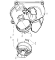
- FIG. 3 is a perspective view of a main body and a cap of a motor case. It is sectional drawing which shows the part of an engagement part and an engaged part. It is sectional drawing of the electric actuator which concerns on other embodiment of this invention. It is sectional drawing which shows the non-fixed end part side of an electric motor, and its peripheral part.
- FIG. 3 is a perspective view of a main body and a cap of a motor case. It is sectional drawing which shows the part of an engagement part and an engaged part.
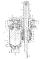
- FIG. 1 is a sectional view of an electric actuator according to one embodiment of the present invention. First, the overall configuration and operation of the electric actuator according to the present embodiment will be described with reference to FIG.
- An electric actuator 1 shown in FIG. 1 includes a motor unit 2 having an electric motor 5, a driving force transmitting mechanism 3 for transmitting a rotational movement of the electric motor 5, and a movement converting mechanism for converting the rotational movement of the electric motor 5 into a linear movement.
- 4 is the main configuration.
- the motor unit 2 includes the electric motor 5, a pair of bus bars 70 as a conductive member for supplying electric power to the electric motor 5, and a motor case 60 that houses the electric motor 5, the bus bar 70, and the like.
- an inexpensive (with brush) DC motor is used as the electric motor 5, but another motor such as a brushless motor may be used.
- the motor case 60 here is configured separately from a case (housing) of the electric motor 5 itself, and a case (a case of an electric actuator that houses the entire electric motor 5 having its own case). Actuator case).
- the motor case 60 includes a cylindrical main body 61 serving as a first case division body that accommodates most of the electric motor 5, and a second case division fixed to one end (the left end in FIG. 1) of the main body 61. And a lid-shaped cap portion 62 as a body.
- Each bus bar 70 is formed by bending a metal plate member into a predetermined shape, and is held by a resin holder 71, respectively. Further, each bus bar 70 is connected by welding to a motor terminal 5 d (see FIG. 2) of the electric motor 5 in a state where the holder 71 is fixed to an end (the left end in FIG. 1) of the electric motor 5. ing.
- the cap portion 62 is provided with a cylindrical connector portion 62a that protrudes in the axial direction, and the inner peripheral side of the connector portion 62a has a distal end portion of each bus bar 70 (the side opposite to the side connected to the motor terminal 5d). End). By connecting the other end of a power line extending from a power source (not shown) to the tip of the bus bar 70, power can be supplied from the power source to the electric motor 5.
- the driving force transmission mechanism 3 includes a drive gear 8 on the drive side and a driven gear 9 on the driven side that meshes with the drive gear 8.
- the drive gear 8 and the driven gear 9 are housed in a gear case 10.
- the drive gear 8 is a small-diameter gear having a smaller number of teeth than the driven gear 9, and is attached to the rotating shaft 5 a of the electric motor 5 so as to rotate integrally therewith.
- the driven gear 9 is a large-diameter gear having more teeth than the drive gear 8, and is attached to a nut 17, which will be described later, constituting the motion conversion mechanism 4 so as to rotate integrally therewith. ing.
- the drive gear 8 is rotatably supported by two bearings 11 and 12 at both ends in the axial direction.
- One of the two bearings 11 and 12 (the left side in FIG. 1) is held by being fitted into a cylindrical bearing holding member 13 fixed to an end of the electric motor 5, and the other (see FIG. 1).
- the bearing 12 (on the right side in FIG. 1) is held by being fitted into the gear case 10.
- the driven gear 9 is rotatably supported together with the nut 17 by double-row bearings 14 provided on the outer peripheral surface of the nut 17.
- the double-row bearings 14 are housed in a cylindrical sleeve 15 provided in the gear case 10, and movement in the axial direction is restricted by a retaining ring 16 mounted on the inner peripheral surface of the sleeve 15.
- the drive gear 8 rotates integrally with the rotating shaft 5a, and the driven gear 9 rotates in conjunction with this.
- the rotation is reduced and the rotational torque is increased.
- the drive gear 8 and the driven gear 9 may be constituted by gears having the same number of teeth, and the rotational motion from the electric motor 5 may be transmitted without deceleration.
- the motion conversion mechanism 4 is a ball screw mechanism having a nut 17 as a rotating member, a screw shaft 18 as a direct acting member, and a number of balls 19.
- Helical grooves are formed on the inner peripheral surface of the nut 17 and the outer peripheral surface of the screw shaft 18, respectively, and a ball 19 is rotatably accommodated between these spiral grooves.
- the nut 17 is provided with a circulation member (not shown), and the circulation member causes the ball 19 to circulate along the spiral groove.
- the screw shaft 18 is inserted through the inner periphery of the nut 17 and is arranged in parallel with the rotating shaft 5 a of the electric motor 5.
- a connection hole 18a is provided at the front end (left end in FIG. 1) of the screw shaft 18.
- a fastener such as a bolt
- the screw shaft 18 and the operation target are illustrated.
- the corresponding part of the used equipment is not connected.
- the rear end of the screw shaft 18 (the end opposite to the end on the operation target side) is covered with a screw shaft case 20.
- the screw shaft case 20 is fixed to the gear case 10 on the side opposite to the side where the motor case 60 is fixed.
- a rotation preventing pin 21 is provided as a rotation restricting member for restricting the rotation of the screw shaft 18.
- the detent pin 21 is attached to the screw shaft 18 in a direction orthogonal or intersecting with the axial direction.
- Guide rollers 22 are rotatably attached to both ends of the rotation preventing pins 21 projecting from the rear end of the screw shaft 18 in the radial direction.
- Each guide roller 22 is inserted into a pair of guide grooves 20 a provided in the screw shaft case 20 and extending in the axial direction. As the guide roller 22 moves in the axial direction along the guide groove 20a, the screw shaft 18 moves forward or backward in the axial direction without rotating in the circumferential direction.
- the boot 23 includes a small-diameter end portion 23a, a large-diameter end portion 23b, and a bellows portion 23c connecting and connecting them to expand and contract in the axial direction.
- the small-diameter end 23a is fixed to the outer peripheral surface of the screw shaft 18, and the large-diameter end 23b is fixed to the outer peripheral surface of a tubular boot mounting member 24 attached to the boot cover 25.
- the boot cover 25 is disposed so as to cover the outside of the boot 23, and is integrally formed with the main body 61 of the motor case 60.
- a ventilation filter 26 is provided in the screw shaft case 20.
- the ventilation filter 26 communicates with the internal space of the boot 23 through the inside of the electric actuator 1, and when the boot 23 expands and contracts, air flows in or out through the ventilation filter 26, thereby suppressing deformation of the bellows portion 23 c.
- a magnet 27 serving as a sensor target for detecting the axial position of the screw shaft 18 is provided on the outer peripheral surface of the screw shaft 18.
- a stroke sensor (not shown) is provided on the outer periphery of the motor case 60. When the screw shaft 18 moves forward or backward, the stroke sensor detects a change in the magnetic field (for example, the direction and strength of the magnetic flux density) of the magnet 27 that moves with the screw shaft 18, so that the axial position of the magnet 27, and thus the screw shaft 18 axial positions are detected.
- a plate-like stay 40 as a support member is fixed to two end faces of the electric motor 5 on the side where the rotating shaft 5 a protrudes.
- a hole 40a is provided in the center of the stay 40, and two bolts 41 are provided on the stay 40 in a state where the rotary shaft 5a of the electric motor 5 is inserted through the hole 40a.
- the stay 40 is fixed to the end face of the electric motor 5 by screwing into the screw hole 5b provided on the end face of the electric motor 5 through the bolt insertion hole 40b.
- the stay 40 is provided with bolt insertion holes 40c through which another two bolts 42 are inserted, and the bolts 42 are inserted into these bolt insertion holes 40c, and as shown in FIG.
- the stay 40 is fixed to the gear case 10 by screwing it into the screw hole 10 a provided in the gear case 10. Thereby, the electric motor 5 is fixed to the gear case 10 via the stay 40.
- the electric motor 5 is fixed to the gear case 10 via the stay 40 at one axial end thereof.
- the other end of the electric motor 5 in the axial direction is not fastened to the motor case 60 by bolts or the like. If there is no support for the electric motor 5 at the other end side (hereinafter, referred to as “anti-fixed end side”), since the electric motor 5 is cantilevered, vibration from outside (for example, There is a problem in applying an electric actuator in a vibration environment exposed to vibration from an engine or vibration generated during running of a vehicle.
- the deflection of the electric motor 5 tends to increase particularly at a position apart from the fixed end of the electric motor 5 (opposite the fixed end).
- the welded portion between the motor terminal 5d and the bus bar 70 is damaged due to the vibration. For example, there is a possibility that these connection states cannot be maintained satisfactorily.
- the holder 71 fixed to the electric motor 5 collides with the inner surface of the motor case 60 before the electric motor 5 when the deflection occurs on the side opposite to the fixed end of the electric motor 5, the collision While the movement (shake) of the holder 71 is regulated by the force (force in the direction opposite to the direction of the shake), the non-fixed end of the electric motor 5 is further moved toward the inner surface of the motor case 60 by the inertial movement due to the shake. Because of the movement, movements in opposite directions occur between the holder 71 and the electric motor 5. In such a case, the opposing movement of the holder 71 and the electric motor 5 applies a load in a direction in which the motor terminal 5d and the bus bar 70 are separated from each other at a welding location. When such a load is repeatedly applied to the welded portion, the welded portion is damaged due to fatigue or the like, and the electric actuator 1 breaks down (control becomes impossible).
- the following measures are taken in order to highly suppress the vibration on the side opposite to the fixed end of the electric motor 5.
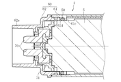
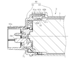
- FIG. 4 is a cross-sectional view of the electric motor on the side opposite to the fixed end and its peripheral portion.
- the outer peripheral surface of the electric motor 5 on the side opposite to the fixed end is connected to the motor case in order to suppress the vibration of the electric motor 5 on the side opposite to the fixed end.
- An O-ring 50 as an elastic member is provided between the main body 60 and the inner peripheral surface of the main body 61.
- the O-ring 50 is held between the electric motor 5 and the main body 61 of the motor case 60 in a state sandwiched in the radial direction.
- the O-ring 50 is provided to the electric motor 5 by a convex position regulating portion 61 c provided on the inner peripheral surface of the main body 61 and an end surface 62 d of the cap portion 62 fitted on the inner peripheral of the main body 61. Axial movement is restricted.
- a plurality of convex position restricting portions 61c extending in the circumferential direction are provided on the inner peripheral surface of the main body 61.
- the position restricting portions 61c are provided intermittently in the circumferential direction, but may be annular position restricting portions 61c provided continuously in the circumferential direction.
- the cap portion 62 is provided with a pair of claw-shaped engaging portions 62b at positions symmetrical with each other by 180 °.
- the main body 61 is provided with a pair of introduction portions 61a into which the engagement portions 62b are introduced.
- an engaged portion 61b capable of engaging with the engaging portion 62b is provided in the introduction portion 61a.
- the engagement structure between the engagement portion 62b and the engaged portion 61b is a so-called snap-fit type engagement structure.
- the end face 62d of the cap part 62 assembled in this manner faces the O-ring 50 mounted in the main body part 61, so that the O face between the end face 62d of the cap part 62 and the position regulating part 61c.
- the ring 50 is held.
- the end face 62d of the cap portion 62 and the position restricting portion 61c may be in a state of being in contact with the O-ring 50 or may be in a non-contact state.
- the O-ring 50 is restricted from moving in the axial direction of the electric motor 5 by the end face 62d of the cap portion 62 and the position restricting portion 61c.
- the O-ring 50 as the elastic member is formed between the outer peripheral surface on the side opposite to the fixed end of the electric motor 5 and the inner peripheral surface of the main body 61 of the motor case 60.
- the non-fixed end side of the electric motor 5 is elastically supported by the O-ring 50. That is, in the present embodiment, the non-fixed end of the electric motor 5, the holder 71 fixed to the non-fixed end, and the bus bar 70 held by the holder 71 are connected to the motor case 60.
- the electric motor 5 is not fixed to the motor case 60 via the O-ring 50, so that the electric motor 5 is elastic. Supported by Thus, even if a run-out occurs on the side opposite to the fixed end of the electric motor 5, the run-out is absorbed by the O-ring 50, thereby suppressing the run-out and preventing the collision of the holder 71 with the inner surface of the motor case 60. Can be avoided. Alternatively, even if the holder 71 collides with the inner surface of the motor case 60, the impact due to the collision can be suppressed. As a result, the load at the welding point between the motor terminal 5d and the bus bar 70 due to the collision can be reduced, and damage to the welding point can be prevented.
- the vibration suppressed by the O-ring 50 is not limited to the vibration in the radial direction of the electric motor 5, and the vibration in any other direction can be suppressed. That is, due to the frictional force of the O-ring 50 generated between the electric motor 5 and the motor case 60 and the elastic force acting in various directions of the O-ring 50, the vibration in any direction crossing the radial direction of the electric motor 5 is also reduced. It is possible to suppress.
- the run-out on the side opposite to the fixed end of the electric motor 5 can be suppressed to a high degree, so that the connection state between the motor terminal 5d and the bus bar 70 can be maintained even under a severe vibration environment. It is possible to provide a highly reliable electric actuator that can be maintained well.
- the axial movement of the O-ring 50 is regulated by the end surface 62d of the cap portion 62 and the position regulating portion 61c of the main body 61, so that the O-ring 50 is not fixed to the electric motor 5 in a reverse direction.
- the position can be held at the end side. Accordingly, it is possible to prevent the O-ring 50 from moving in the axial direction of the electric motor 5 and falling off due to vibration from the outside, and to prevent the O-ring 50 from moving toward the fixed end of the electric motor 5.
- the intended function of the ring 50 (shake suppression on the side opposite to the fixed end of the electric motor 5) can be reliably exerted over a long period of time.
- a convex position regulating portion is provided on the inner peripheral surface of the cap portion 62, and the axial movement of the O-ring 50 is regulated by the position regulating portion and the end surface of the main body 61. It is also possible to configure.
- the O-ring 50 is preferably made of a heat-resistant material (for example, fluorine rubber (FKM) or the like) because the temperature of the electric motor 5 may become high when the electric actuator 1 operates.
- the elastic member is not limited to the O-ring, and any other elastic member may be used as long as the vibration of the electric motor can be suppressed.
- FIGS. 7 to 12 other embodiments of the present invention will be described, mainly regarding portions different from the above-described embodiment and portions not described.
- members and components having the same configurations as those of the above-described embodiment are denoted by the same reference numerals as those in FIGS. 1 to 6, and the description thereof is partially omitted.
- the electric actuator 1 in order to suppress the run-out on the non-fixed end side (the end side not fastened to the motor case 60) of the electric motor 5.
- a rubber O-ring 38 as a second elastic member different from the O-ring 50 is provided between the holder 71 for holding the bus bar 70 and the cap 62 of the motor case 60 in the axial direction of the electric motor 5.
- the O-ring 50 as the first elastic member is provided between the outer peripheral surface of the electric motor 5 on the side opposite to the fixed end and the inner peripheral surface of the motor case 60.
- the O-ring 50 is not shown in FIGS. 7, 8 and 12.
- the holder 71 has a tubular portion 71a and a flange portion 71b protruding outside the outer peripheral surface of the tubular portion 71a.
- the holder 71 is integrated with the bus bar 70 by insert molding. Rectangular recesses 71c are formed in the flange portion 71b at positions that are symmetrical with each other by 180 °, and are arranged so that one end 70a of each bus bar 70 is exposed in each recess 71c.
- the other end 70b of each bus bar 70 is disposed so as to protrude in the axial direction from the space partitioned into the two cylindrical portions 71a.
- the flange 71b is provided with a pair of convex fitting portions 71d at locations different in phase by 90 ° from the concave portions 71c.
- the convex fitting portion 71 d of the holder portion 71 is axially fitted to the concave fitting portion 5 c of the electric motor 5, the holder portion 71 Fixed to the fixed end. Then, in this state, one end 70a of each bus bar 70 is welded to the motor terminal 5d, so that they are electrically connected.
- an axial mounting surface 71 e on which the O-ring 38 is mounted is disposed along the axial direction of the cylindrical portion 71 a. , Is formed in a direction intersecting with the axial direction of the cylindrical portion 71a, and a stepped portion formed by an abutting surface 71f against which the O-ring 38 is abutted is formed.
- the O-ring 38 is mounted on the outer periphery of the mounting surface 71e, and is positioned in the axial direction by being abutted against the abutting surface 71f.
- the cap portion 62 is provided with a pair of claw-shaped engaging portions 62b at positions symmetrical with each other by 180 °.
- the main body 61 is provided with a pair of introduction portions 61a into which the engagement portions 62b are introduced.
- an engaging portion 62b and a to-be-engaged portion 61b which are snap-fit type engaging structures, are provided in the introduction portion 61a, as in the above-described embodiment.
- an annular protruding wall portion 62 c that is continuous in the circumferential direction is provided on the inner peripheral surface of the connector portion 62 a of the cap portion 62.
- the annular protruding wall portion 62c cooperates with the abutment surface 71f provided on the holder portion 71 to form the O-ring 38 in a state where the cap portion 62 is attached to the main body portion 61. It is the part that is held between the two. That is, while the O-ring 38 is mounted on the mounting surface 71 e of the holder 71, the holder 71 is fixed to the electric motor 5, and the electric motor 5 is housed in the main body 61, the cap is closed.
- the O-ring 38 When the portion 62 is attached to the main body 61, the O-ring 38 is pushed in the axial direction of the electric motor 5 by the projecting wall portion 62 c of the cap portion 62, and the O-ring 38 is pressed against the abutting surface 71 f of the holder portion 71. Can be As a result, the O-ring 38 is held between the projecting wall portion 62c and the abutting surface 71f while being compressed in the axial direction of the electric motor 5.
- the O-ring 38 as the second elastic member is provided between the abutting surface 71f of the holder 71 and the protruding wall 62c of the cap 62.
- the non-fixed end side of the electric motor 5 is elastically supported by the O-ring 38. That is, in the present embodiment, the non-fixed end of the electric motor 5, the holder 71 fixed to the non-fixed end, and the bus bar 70 held by the holder 71 are connected to the motor case 60.
- the electric motor 5 is not fixed because the holder 71 is in contact with the motor case 60 via the O-ring 38.
- the end side is elastically supported. Accordingly, even if a run-out occurs on the side opposite to the fixed end of the electric motor 5, the run-out is absorbed by the O-ring 38, thereby suppressing the run-out and preventing the collision of the holder 71 with the inner surface of the motor case 60. Can be avoided. Alternatively, even if the holder 71 collides with the inner surface of the motor case 60, the impact due to the collision can be suppressed. As a result, the load at the welding point between the motor terminal 5d and the bus bar 70 due to the collision can be reduced, and damage to the welding point can be prevented.
- the axial rebound of the electric motor 5 by the O-ring 38 causes the axial vibration of the electric motor 5 (the axial direction of the vibration).
- the vibration suppressed by the O-ring 38 is not limited to the vibration in the axial direction of the electric motor 5, and the vibration in any other direction can be suppressed. That is, due to the frictional force of the O-ring 38 generated between the holder 71 and the cap 62 and the elastic force acting in various directions of the O-ring 38, the vibration in an arbitrary direction intersecting with the axial direction of the electric motor 5 is also reduced. It is possible to suppress.
- the run-out on the side opposite to the fixed end of the electric motor 5 can be suppressed to a high degree, so that the connection state between the motor terminal 5d and the bus bar 70 can be maintained even under a severe vibration environment. It is possible to provide a highly reliable electric actuator that can be maintained well.
- the engaging portion 62b of the cap portion 62 and the main body portion 61 are provided. Axial play with the engaged portion 61b can be eliminated. That is, since the O-ring 38 generates the above-described elastic repulsive force in the axial direction, the elastic repulsive force urges the engaging portion 62b in the direction of engagement with the engaged portion 61b. The joining portion 62b is securely engaged with the engaged portion 61b. Thereby, the assemblability of the cap part 62 to the main body part 61 is improved.
- the O-ring 38 is adopted as the second elastic member, and the O-ring 38 is mounted on the outer periphery of the cylindrical portion 71a, so that the second elastic member can be easily mounted.
- the two elastic members are not limited to the O-ring, and other elastic members may be used as long as the vibration of the electric motor can be suppressed.
- the case of the electric actuator 1 includes the motor case 60 including the main body 61 and the cap 62, the gear case 10, the screw shaft case 20, and the boot cover 25.
- the structure of the case is not limited to the above embodiment.
- the shape and division structure of the case can be appropriately changed according to the change of the specification of the internal structure of the electric actuator and the assembling property.
Landscapes
- Engineering & Computer Science (AREA)
- Power Engineering (AREA)
- General Engineering & Computer Science (AREA)
- Mechanical Engineering (AREA)
- Motor Or Generator Frames (AREA)
- Connection Of Motors, Electrical Generators, Mechanical Devices, And The Like (AREA)
Abstract
ケースと、ケースに内蔵された電動モータ5と、電動モータ5の回転運動を直線運動に変換する運動変換機構4とを備え、電動モータ5が、その軸方向の一端部側でケース(ギヤケース10)に対して固定された電動アクチュエータにおいて、電動モータ5におけるケース(ギヤケース10)に固定された一端部側とは反対の他端部側で、電動モータ5の外周面とケース(モータケース60)の内周面との間に第1弾性部材50を設けた。
Description
本発明は、電動アクチュエータに関する。
近年、車両等の省力化、低燃費化のために電動化が進み、例えば、自動車の自動変速機やブレーキ、ステアリング等の操作を電動機の力で行うシステムが開発され、市場に投入されている。
このような用途に使用されるアクチュエータとして、例えば、下記特許文献1には、電動モータの回転運動を直線運動に変換して出力するボールねじ機構を備えるものが開示されている。また、特許文献1には、電動モータの軸方向の一端部側に板状のステーを取り付け、そのステーを介して電動モータをアクチュエータケースにボルトで締結することで、振動に対する電動モータの位置保持力を向上させた構成が提案されている。
しかしながら、上記特許文献1に提案されている構成においては、電動モータが、ステーが設けられた側とは反対側では全く支持されていない片持ち支持の状態であるため、外部からの振動(エンジンからの振動や車両走行中に生じる振動など)が電動モータに伝わると、電動モータの支持されていない側で振れが生じる可能性がある。従って、特許文献1に提案されている構成は、厳しい振動条件下での適用には十分ではなく、改善が必要であった。
そこで、本発明は、電動モータの振れを高度に抑制することが可能な電動アクチュエータを提供することを目的とする。
上記課題を解決するため、本発明は、ケースと、ケースに内蔵された電動モータと、電動モータの回転運動を直線運動に変換する運動変換機構とを備え、電動モータが、その軸方向の一端部側でケースに対して固定された電動アクチュエータにおいて、電動モータにおけるケースに固定された一端部側とは反対の他端部側で、電動モータの外周面とケースの内周面との間に第1弾性部材を設けたことを特徴とする。
このように、電動モータにおけるケースに固定された一端部側とは反対の他端部側で、電動モータの外周面とケースの内周面との間に第1弾性部材を設けることで、電動モータの他端部側が第1弾性部材によって弾性的に支持されるようになる。これにより、外部からの振動が電動モータに伝わったとしても、電動モータの他端部側での振れが第1弾性部材によって吸収されることで、振れが高度に抑制される。
また、電動モータの外周面とケースの内周面とによって第1弾性部材を径方向に圧縮した状態で挟んで保持することで、第1弾性部材に径方向の弾性反発力が生じる。従って、この径方向の弾性反発力により電動モータの径方向の振れ(振れの径方向成分)を抑制することができる。なお、第1弾性部材によって抑制される振れは、電動モータの径方向の振れだけに限らず、他の任意の方向の振れも抑制することが可能である。すなわち、電動モータとケースとの間で生じる第1弾性部材の摩擦力や第1弾性部材の種々の方向に作用する弾性力によって、電動モータの径方向と交差する任意の方向の振れも抑制することができる。
ケースは、互いに組み付け可能に構成された第1ケース分割体と第2ケース分割体とを有するものであってもよい。この場合、第1ケース分割体及び第2ケース分割体の一方のケース分割体の内周面に凸状の位置規制部を設け、その位置規制部と、一方のケース分割体に組み付けられた他方のケース分割体の端面とによって、電動モータに対する第1弾性部材の軸方向両側への移動を規制することで、第1弾性部材を電動モータの他端部側で位置保持しておくことができる。これにより、外部からの振動によって第1弾性部材が電動モータの軸方向に移動して脱落したり、第1弾性部材が電動モータの他端部側とは反対側(ケースに固定された端部側)へ移動したりするのを防止できるので、第1弾性部材による所期の機能(電動モータの他端部側での振れ抑制)を長期に亘って確実に発揮させることができる。
第1弾性部材は、電動アクチュエータの作動時に電動モータが高温になることを考慮して、耐熱性材料で構成されていることが望ましい。
また、電動アクチュエータは、電動モータのケースに対して固定された一端部側とは反対の他端部側でモータ端子に接続された導電部材を備えるものであってもよい。この場合、導電部材とケースとの間に第2弾性部材を設けることで、電動モータの他端部側が第2弾性部材によって弾性的に支持されるようになる。これにより、外部からの振動が電動モータに伝わったとしても、電動モータの他端部側での振れが第2弾性部材によって吸収されることで、振れが高度に抑制される。
電動アクチュエータが導電部材を保持するホルダ部を備える場合、ホルダ部とケースとの間に第2弾性部材を挟んで保持するようにしてもよい。この場合、電動モータの他端部側はホルダ部を介して弾性的に支持されるので、第2弾性部材によって電動モータの他端部側での振れが高度に抑制される。
また、ホルダ部とケースとによって第2弾性部材を電動モータの軸方向に挟んで保持するように構成してもよい。この場合、第2弾性部材が電動モータの軸方向に挟まれていることで、第2弾性部材にその軸方向の弾性反発力が生じる。従って、この軸方向の弾性反発力により電動モータの軸方向の振れ(振れの軸方向成分)を抑制することができる。なお、第2弾性部材によって抑制される振れは、電動モータの軸方向の振れだけに限らず、他の任意の方向の振れも抑制することが可能である。すなわち、ホルダ部とケースとの間で生じる第2弾性部材の摩擦力や第2弾性部材の種々の方向に作用する弾性力によって、電動モータの軸方向と交差する任意の方向の振れも抑制することができる。
また、第2弾性部材をOリングとし、ホルダ部に筒状部を設け、筒状部の外周にOリングを装着してもよい。このような構成とすることで、第2弾性部材の装着が行いやすくなり、作業性が向上する。
また、ケースが、互いに係合して組み付け可能に構成された第1ケース分割体と第2ケース分割体とを有する場合、第1ケース分割体に組み付けられた第2ケース分割体と、ホルダ部との間に、第2弾性部材を挟んで保持してもよい。この場合、第2ケース分割体とホルダ部とによって挟まれて保持されている第2弾性部材の弾性反発力によって、第2ケース分割体が第1ケース分割体に対して係合する方向に付勢されることで、ケース分割体同士の係合箇所におけるガタつきを無くし、ケース分割体同士の係合を確実に行わせることができる。
本発明によれば、電動モータの振れを高度に抑制することができるので、電動モータの振れに起因する部品の破損などの不具合が生じにくくなり、厳しい振動環境下においても適用可能な信頼性の高い電動アクチュエータを提供できるようになる。
図1は、本発明の実施の一形態に係る電動アクチュエータの断面図である。まず、図1を参照しつつ、本実施形態に係る電動アクチュエータの全体構成及び動作について説明する。
図1に示す電動アクチュエータ1は、電動モータ5を有するモータ部2と、電動モータ5の回転運動を伝達する駆動力伝達機構3と、電動モータ5の回転運動を直線運動に変換する運動変換機構4とを主な構成としている。
モータ部2は、電動モータ5と、電動モータ5に電力供給するための導電部材としての一対のバスバー70と、電動モータ5やバスバー70等を収容するモータケース60とを備えている。本実施形態では、電動モータ5として、安価な(ブラシ付き)DCモータを用いているが、ブラシレスモータ等の他のモータを用いてもよい。なお、ここでいうモータケース60は、電動モータ5自体が有するケース(ハウジング)とは別体で構成されたものであり、独自のケースを有する電動モータ5全体が収容される電動アクチュエータのケース(アクチュエータケース)である。
モータケース60は、電動モータ5の大部分を収容する第1ケース分割体としての円筒状の本体部61と、本体部61の一端部(図1における左端部)に固定された第2ケース分割体としての蓋状のキャップ部62とで構成されている。各バスバー70は、金属製の板部材を所定形状に曲げ加工して形成されており、それぞれ樹脂製のホルダ部71によって保持されている。また、各バスバー70は、ホルダ部71が電動モータ5の端部(図1おける左端部)に固定された状態で、電動モータ5のモータ端子5d(図2参照)に対して溶接により接続されている。キャップ部62には軸方向に突出する筒状のコネクタ部62aが設けられており、コネクタ部62aの内周側には各バスバー70の先端部(モータ端子5dに接続される側とは反対側の端部)が配置されている。このバスバー70の先端部に対し、図示しない動力電源から延びる動力線の相手側端子が接続されることで、動力電源から電動モータ5へ電力が供給可能な状態となる。
駆動力伝達機構3は、駆動側のドライブギヤ8と、これと噛み合う被駆動側のドリブンギヤ9とで構成されている。ドライブギヤ8及びドリブンギヤ9は、ギヤケース10内に収容されている。ドライブギヤ8は、ドリブンギヤ9よりも歯数の少ない小径のギヤであり、電動モータ5の回転軸5aに対してこれと一体的に回転するように取り付けられている。これに対して、ドリブンギヤ9は、ドライブギヤ8よりも歯数の多い大径のギヤであり、運動変換機構4を構成する後述のナット17に対してこれと一体的に回転するように取り付けられている。
また、ドライブギヤ8は、その軸方向の両端部にて2つの軸受11,12によって回転可能に支持されている。2つの軸受11,12のうち、一方(図1において左側)の軸受11は、電動モータ5の端部に固定された筒状の軸受保持部材13内に嵌め込まれることによって保持され、他方(図1において右側)の軸受12は、ギヤケース10内に嵌め込まれることによって保持されている。ドリブンギヤ9は、ナット17の外周面に設けられた複列の軸受14によってナット17と共に回転可能に支持されている。複列の軸受14は、ギヤケース10に設けられた筒状のスリーブ15内に収容され、スリーブ15の内周面に装着された止め輪16によって軸方向への移動が規制されている。複列の軸受14としては、ナット17を安定的かつ確実に支持することができるように、ラジアル荷重に加えて、両方向のアキシャル荷重を支承できる複列アンギュラ玉軸受を用いることが好ましい。
電動モータ5が駆動を開始し、電動モータ5の回転軸5aが回転すると、回転軸5aと一体的にドライブギヤ8が回転し、これに連動してドリブンギヤ9が回転する。このとき、電動モータ5からの回転運動は、歯数の少ないドライブギヤ8から歯数の多いドリブンギヤ9へ伝達されるので、減速されて回転トルクが増加する。このように、ドライブギヤ8とドリブンギヤ9間での減速により回転トルクを増加させて出力することで、小型の電動モータを用いても十分な出力が得られるようになる。なお、本実施形態とは異なり、ドライブギヤ8とドリブンギヤ9とを同じ歯数のギヤで構成し、電動モータ5からの回転運動を減速せずに伝達するようにしてもよい。
運動変換機構4は、回転部材としてのナット17と、直動部材としてのねじ軸18と、多数のボール19とを有するボールねじ機構である。ナット17の内周面とねじ軸18の外周面には、それぞれ螺旋状溝が形成されており、これらの螺旋状溝の間にボール19が転動可能に収容されている。また、ナット17には図示しない循環部材が設けられており、この循環部材によってボール19が螺旋状溝に沿って循環するように構成されている。
ねじ軸18は、ナット17の内周に挿通され、電動モータ5の回転軸5aと平行に配置されている。ねじ軸18の前端部(図1における左端部)には、連結孔18aが設けられており、この連結孔18aにボルト等の締結具を挿入することで、ねじ軸18と操作対象である図示しない使用機器の対応部位とが連結される。電動モータ5の回転運動がドライブギヤ8及びドリブンギヤ9を介してナット17に伝達されると、ナット17が回転することで、ねじ軸18が軸方向の一方(前進方向又は後退方向)へ移動する。反対に、電動モータ5が逆回転した場合は、ドライブギヤ8及びドリブンギヤ9を介して回転運動がナット17に伝達されて、ねじ軸18が軸方向の他方へ移動する。このように、電動モータ5の正逆回転によって、ねじ軸18が前進又は後退することで、ねじ軸18の前端部に連結された操作対象が操作される。
ねじ軸18の後端部(操作対象側の端部とは反対側の端部)は、ねじ軸ケース20によって覆われている。ねじ軸ケース20は、ギヤケース10に対してモータケース60が固定される側とは反対側で固定されている。
また、ねじ軸18の後端部には、ねじ軸18の回転を規制する回転規制部材としての回り止めピン21が設けられている。回り止めピン21は、ねじ軸18に対してその軸方向と直交又は交差する方向に取り付けられている。ねじ軸18の後端部から外径方向に突出する回り止めピン21の両端部には、それぞれガイドローラ22が回転可能に取り付けられている。各ガイドローラ22は、ねじ軸ケース20に設けられた軸方向に延びる一対のガイド溝20a内に挿入されている。ガイドローラ22がガイド溝20aに沿って軸方向へ移動することで、ねじ軸18は周方向に回転することなく軸方向に前進又は後退する。
また、ねじ軸18において、ナット17よりも前端部側には、電動アクチュエータ1内に異物が侵入するのを防止するブーツ23と、ブーツ23を保護するためのブーツカバー25とが設けられている。ブーツ23は、小径端部23aと大径端部23bとこれらを繋いで軸方向に伸縮する蛇腹部23cとで構成されている。小径端部23aはねじ軸18の外周面に固定され、大径端部23bはブーツカバー25に取り付けられた筒状のブーツ装着部材24の外周面に固定されている。ブーツカバー25は、ブーツ23の外側を覆うように配置され、モータケース60の本体部61と一体成型されている。
ねじ軸18の往復運動に伴ってブーツ23が伸縮すると、ブーツ23内部の圧力が変動するため、特にねじ軸18の軸方向移動量が大きい場合に内圧変動により蛇腹部23cが過大に変形して、蛇腹部23cの耐久性が低下する虞がある。そこで、ブーツ23の内圧変動による蛇腹部23cの破損を防ぐために、ねじ軸ケース20に通気フィルタ26を設けている。通気フィルタ26は、電動アクチュエータ1内を通ってブーツ23の内部空間と連通しており、ブーツ23が伸縮すると、通気フィルタ26を通してエアが流入又は流出することで、蛇腹部23cの変形が抑制される。
また、ねじ軸18の外周面には、ねじ軸18の軸方向位置を検出するためのセンサターゲットとなる磁石27が設けられている。一方、モータケース60の外周には、図示しないストロークセンサが設けられている。ねじ軸18が前進又は後退すると、これに伴って移動する磁石27の磁場(例えば磁束密度の向き及び強さ)の変化をストロークセンサが検出することにより、磁石27の軸方向位置、ひいてはねじ軸18の軸方向位置が検出される。
ここで、図2及び図3を参照しつつ、本実施形態に係る電動アクチュエータ1における電動モータ5の支持構造について説明する。
図2に示すように、電動モータ5の回転軸5aが突出する側の端面には、支持部材としての板状のステー40が2本のボルト41によって固定される。詳しくは、ステー40の中央部には孔部40aが設けられており、この孔部40aに電動モータ5の回転軸5aを挿通させた状態で、2本のボルト41をステー40に設けられたボルト挿通孔40bを通して電動モータ5の端面に設けられたねじ孔5bにねじ込むことにより、ステー40が電動モータ5の端面に対して固定される。また、ステー40には別の2本のボルト42を挿通させるボルト挿通孔40cが設けられており、これらのボルト挿通孔40cにボルト42を挿通させ、図3に示すように、各ボルト42をギヤケース10に設けられたねじ孔10aにねじ込むことで、ステー40がギヤケース10に対して固定される。これにより、電動モータ5はステー40を介してギヤケース10に固定される。
このように、本実施形態に係る電動アクチュエータ1において、電動モータ5は、その軸方向の一端部側でステー40を介してギヤケース10に対して固定されている。一方、電動モータ5の軸方向の他端部側は、ボルト等によるモータケース60への締結は行われていない。仮に、この他端部側(以下、「反固定端部側」という。)での電動モータ5に対する支持が全くない場合、電動モータ5が片持ち支持となるため、外部からの振動(例えば、エンジンからの振動や車両走行中に生じる振動など)に曝される振動環境下では、電動アクチュエータを適用するにあたって課題がある。具体的には、外部からの振動が電動モータ5に伝わると、特に電動モータ5の固定端部から離れた箇所(反固定端部側)で電動モータ5の振れが大きくなる傾向にあるため、本実施形態のように、モータ端子5dとバスバー70とが電動モータ5の反固定端部側で接続されている構成においては、その振れによる影響でモータ端子5dとバスバー70との溶接個所が破損するなどしてこれらの接続状態が良好に維持できなくなる虞がある。例えば、電動モータ5の反固定端部側に振れが生じた場合に、電動モータ5に固定されているホルダ部71が電動モータ5よりも先にモータケース60の内面に衝突すると、衝突による反力(振れの方向とは反対方向の力)によりホルダ部71の動き(振れ)が規制される一方、電動モータ5の反固定端部側は振れによる慣性運動によってさらにモータケース60の内面側へ動くので、ホルダ部71と電動モータ5との間で相反する方向の運動が発生する。このような場合、ホルダ部71と電動モータ5との相反する方向の運動によって、モータ端子5dとバスバー70との溶接箇所において互いに分離する方向の負荷がかかる。そして、斯かる負荷が溶接箇所に繰り返し加わることで、溶接個所が疲労等により破損し、ひいては電動アクチュエータ1が故障することになる(制御不能となる)。
そこで、本実施形態では、電動モータ5の反固定端部側での振動を高度に抑制するため、以下のような対策を講じている。
図4は、電動モータの反固定端部側及びその周辺部の断面図である。
図4に示すように、本実施形態に係る電動アクチュエータ1においては、電動モータ5の反固定端部側での振れを抑制するため、電動モータ5の反固定端部側の外周面とモータケース60の本体部61の内周面との間に弾性部材としてのOリング50を設けている。Oリング50は、電動モータ5とモータケース60の本体部61とによって径方向に挟まれた状態で保持されている。また、Oリング50は、本体部61の内周面に設けられた凸状の位置規制部61cと、本体部61の内周に嵌め込まれたキャップ部62の端面62dとによって、電動モータ5に対する軸方向への移動が規制されている。
図5に示すように、本体部61の内周面には、周方向に延びる凸状の位置規制部61cが複数設けられている。本実施形態では、位置規制部61cが周方向に断続的に設けられているが、周方向に連続的して設けられた環状の位置規制部61cであってもよい。
また、図5に示すように、キャップ部62には、互いに180°対称となる位置に爪状に形成された一対の係合部62bが設けられている。一方、本体部61には、係合部62bが導入される一対の導入部61aが設けられている。
図6に示すように、導入部61a内には、係合部62bと係合可能な被係合部61bが設けられている。係合部62bと被係合部61bとの係合構造は、所謂スナップフィット式の係合構造である。係合部62bが電動モータ5の軸方向に沿って導入部61aに導入されると、各係合部62bが互いに離れる方向に撓んで弾性変形し、被係合部61bに達したときに各係合部62bが弾性復帰することによって被係合部61bと係合した状態又は係合可能な状態となり、キャップ部62が本体部61に対して組み付けられる。
このようにして組み付けられたキャップ部62の端面62dが、本体部61内に装着されたOリング50に対して対向することで、キャップ部62の端面62dと位置規制部61cとの間でOリング50が保持される。なお、この状態で、キャップ部62の端面62d及び位置規制部61cは、Oリング50に対して接触した状態であってもよいし、非接触の状態であってもよい。これにより、Oリング50はキャップ部62の端面62dと位置規制部61cとによって電動モータ5の軸方向への移動が規制される。
以上のように、本実施形態に係る電動アクチュエータ1においては、弾性部材としてのOリング50が電動モータ5の反固定端部側の外周面とモータケース60の本体部61の内周面との間に設けられていることで、電動モータ5の反固定端部側がOリング50によって弾性的に支持される。すなわち、本実施形態においては、電動モータ5の反固定端部側と、この反固定端部側に固定されているホルダ部71、及びホルダ部71に保持されるバスバー70が、モータケース60の内面に対して隙間を介して配置され、モータケース60に対して固定されていないが、電動モータ5の反固定端部側がOリング50を介してモータケース60に接触していることで弾性的に支持される。これにより、電動モータ5の反固定端部側に振れが生じたとしても、その振れがOリング50によって吸収されることで、振れが抑制され、モータケース60の内面に対するホルダ部71の衝突を回避することができる。あるいは、モータケース60の内面に対してホルダ部71が衝突したとしても、その衝突による衝撃を抑制することができる。その結果、衝突に起因するモータ端子5dとバスバー70との溶接個所における負荷を低減することができ、溶接個所の破損を防止できるようになる。
ここで、本実施形態では、Oリング50が電動モータ5の径方向に圧縮されて保持されているため、Oリング50による径方向の弾性反発力によって、電動モータ5の径方向の振れ(振れの径方向成分)を抑制することが可能である。なお、Oリング50によって抑制される振れは、電動モータ5の径方向の振れだけに限らず、他の任意の方向の振れも抑制することが可能である。すなわち、電動モータ5とモータケース60との間で生じるOリング50の摩擦力やOリング50の種々の方向に作用する弾性力によって、電動モータ5の径方向と交差する任意の方向の振れも抑制することが可能である。
このように、本実施形態においては、電動モータ5の反固定端部側の振れを高度に抑制することができるので、厳しい振動環境下であってもモータ端子5dとバスバー70との接続状態を良好に維持することができ、信頼性の高い電動アクチュエータを提供できるようになる。
また、本実施形態のように、キャップ部62の端面62dと本体部61の位置規制部61cとによってOリング50の軸方向移動が規制されることで、Oリング50を電動モータ5の反固定端部側で位置保持しておくことができる。これにより、外部からの振動によってOリング50が電動モータ5の軸方向に移動して脱落したり、Oリング50が電動モータ5の固定端部側へ移動したりするのを防止できるので、Oリング50による所期の機能(電動モータ5の反固定端部側での振れ抑制)を長期に亘って確実に発揮させることができる。また、本実施形態とは反対に、凸状の位置規制部をキャップ部62の内周面に設け、この位置規制部と本体部61の端面とによってOリング50の軸方向移動を規制するように構成することも可能である。
また、Oリング50は、電動アクチュエータ1の作動時に電動モータ5が高温になる場合もあることから、耐熱性材料{例えば、フッ素ゴム(FKM)等}で構成されていることが望ましい。なお、Oリングに限らず、電動モータの振れを抑制できるものであれば他の弾性部材を採用してもよい。
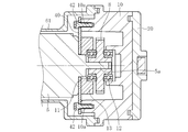
続いて、図7~図12に基づき、本発明の他の実施形態について、主に上述の実施形態とは異なる部分及び説明していない部分について説明する。また、図7~図12において、上述の実施形態と同様の構成の部材や部品については、図1~図6と同一の符号を付すことでこれらの説明を一部省略する。
図7及び図8に示すように、本実施形態に係る電動アクチュエータ1においては、電動モータ5の反固定端部側(モータケース60に締結されていない端部側)での振れを抑制するため、バスバー70とモータケース60との間に、上記Oリング50とは別の第2弾性部材であるゴム製のOリング38を設けている。Oリング38は、バスバー70を保持するホルダ部71とモータケース60のキャップ部62とによって電動モータ5の軸方向に挟まれた状態で保持されている。なお、本実施形態においても、上述の実施形態と同様に、第1弾性部材としてのOリング50が、電動モータ5の反固定端部側の外周面とモータケース60の内周面との間に設けられているが、図7、図8及び図12においてはOリング50を図示省略している。
ここで、Oリング38を挟んで保持するホルダ部71とキャップ部62とのそれぞれの構成について詳しく説明する。
図9に示すように、ホルダ部71は、筒状部71aと、筒状部71aの外周面よりも外側へ突出するフランジ部71bとを有する。また、ホルダ部71は、インサート成型によりバスバー70と一体化されている。フランジ部71bには、互いに180°対称となる位置に矩形の凹部71cが形成されており、各凹部71c内に各バスバー70の一端部70aが露出するように配置されている。一方、各バスバー70の他端部70bは、筒状部71aの2つに仕切られた空間内から軸方向に突出するように配置されている。また、フランジ部71bには、凹部71cとは90°位相が異なる箇所に一対の凸状の嵌合部71dが設けられている。そして、電動モータ5の反固定端部側には、フランジ部71bの凸状の嵌合部71dと嵌合可能な凹状の嵌合部5cが設けられている。図10に示すように、ホルダ部71の凸状の嵌合部71dが電動モータ5の凹状の嵌合部5cに対して軸方向に嵌合することで、ホルダ部71は電動モータ5の反固定端部に対して固定される。そして、この状態で各バスバー70の一端部70aがモータ端子5dに対して溶接されることによりこれらが電気的に接続される。
また、図9に示すように、筒状部71aの先端部側の外周面には、筒状部71aの軸方向に沿って配置され、Oリング38が装着される軸方向の装着面71eと、筒状部71aの軸方向とは交差する方向に配置され、Oリング38が突き当てられる突き当て面71fと、から成る段差部が形成されている。図8に示すように、Oリング38は、装着面71eの外周に装着され、突き当て面71fに突き当てられることで軸方向の一方の位置決めがなされる。
図11に示すように、本実施形態においても、キャップ部62には、互いに180°対称となる位置に爪状に形成された一対の係合部62bが設けられている。一方、本体部61には、係合部62bが導入される一対の導入部61aが設けられている。
図12に示すように、導入部61a内には、上述の実施形態と同様に、スナップフィット式の係合構造である係合部62b及び被係合部61bが設けられている。また、図11及び図12に示すように、キャップ部62が有するコネクタ部62aの内周面には、周方向に渡って連続する環状の突壁部62cが設けられている。
この環状の突壁部62cは、図12に示すように、キャップ部62が本体部61に取り付けられた状態で、ホルダ部71に設けられた突き当て面71fと協働してOリング38を挟んで保持する部分である。すなわち、Oリング38がホルダ部71の装着面71eに装着されると共に、当該ホルダ部71が電動モータ5に対して固定され、さらに、電動モータ5が本体部61に収容された状態で、キャップ部62が本体部61に対して取り付けられると、キャップ部62の突壁部62cによってOリング38が電動モータ5の軸方向に押され、Oリング38がホルダ部71の突き当て面71fに押し付けられる。これにより、Oリング38は電動モータ5の軸方向に圧縮された状態で突壁部62cと突き当て面71fとの間で挟まれて保持される。
以上のように、本実施形態に係る電動アクチュエータ1においては、第2弾性部材としてのOリング38がホルダ部71の突き当て面71fとキャップ部62の突壁部62cとの間に設けられていることで、電動モータ5の反固定端部側がOリング38によって弾性的に支持される。すなわち、本実施形態においては、電動モータ5の反固定端部側と、この反固定端部側に固定されているホルダ部71、及びホルダ部71に保持されるバスバー70が、モータケース60の内面に対して隙間を介して配置され、モータケース60に対して固定されていないが、ホルダ部71がOリング38を介してモータケース60に接触していることで、電動モータ5の反固定端部側が弾性的に支持される。これにより、電動モータ5の反固定端部側に振れが生じたとしても、その振れがOリング38によって吸収されることで、振れが抑制され、モータケース60の内面に対するホルダ部71の衝突を回避することができる。あるいは、モータケース60の内面に対してホルダ部71が衝突したとしても、その衝突による衝撃を抑制することができる。その結果、衝突に起因するモータ端子5dとバスバー70との溶接個所における負荷を低減することができ、溶接個所の破損を防止できるようになる。
本実施形態では、Oリング38が電動モータ5の軸方向に圧縮されて保持されているため、Oリング38による軸方向の弾性反発力によって、電動モータ5の軸方向の振れ(振れの軸方向成分)を抑制することが可能である。なお、Oリング38によって抑制される振れは、電動モータ5の軸方向の振れだけに限らず、他の任意の方向の振れも抑制することが可能である。すなわち、ホルダ部71とキャップ部62との間で生じるOリング38の摩擦力やOリング38の種々の方向に作用する弾性力によって、電動モータ5の軸方向と交差する任意の方向の振れも抑制することが可能である。
このように、本実施形態においては、電動モータ5の反固定端部側の振れを高度に抑制することができるので、厳しい振動環境下であってもモータ端子5dとバスバー70との接続状態を良好に維持することができ、信頼性の高い電動アクチュエータを提供できるようになる。
また、本実施形態のように、Oリング38がキャップ部62とホルダ部71との間で電動モータ5の軸方向に挟まれていることで、キャップ部62の係合部62bと本体部61の被係合部61bとの間での軸方向のガタつきを無くすことができる。すなわち、Oリング38が上述の軸方向の弾性反発力を生じさせることで、その弾性反発力により係合部62bが被係合部61bに対して係合する方向に付勢されるので、係合部62bが被係合部61bに対して確実に係合される。これにより、本体部61に対するキャップ部62の組付け性が向上する。
本実施形態では、第2弾性部材としてOリング38を採用し、Oリング38を筒状部71aの外周に装着することで、第2弾性部材の装着を容易に行えるようにしているが、第2弾性部材はOリングに限らず、電動モータの振れを抑制できるものであれば他の弾性部材を採用することも可能である。また、バスバー70をホルダ部71で保持しない(ホルダ部71を備えない)構成とすることも可能であり、その場合、バスバー70を第2弾性部材に直接接触させてケースとの間で弾性部材を挟むようにしてもよい。
以上、本発明に係る電動アクチュエータの実施形態について説明したが、本発明は上記実施形態に何ら限定されるものではなく、本発明の要旨を逸脱しない範囲内において、さらに種々なる形態で実施し得ることは勿論のことである。
上述の各実施形態では、電動アクチュエータ1のケースが、本体部61とキャップ部62とから成るモータケース60と、ギヤケース10と、ねじ軸ケース20と、ブーツカバー25とで構成されているが、ケースの構造は上述の実施形態のものに限らない。ケースの形状や分割構造は、電動アクチュエータの内部構造の仕様変更や組付け性などに応じて適宜変更可能である。
1 電動アクチュエータ
3 駆動伝達機構
4 運動変換機構
5 電動モータ
38 Oリング(第2弾性部材)
50 Oリング(第1弾性部材)
60 モータケース
61 本体部(第1ケース分割体)
61c 位置規制部
62 キャップ部(第2ケース分割体)
62d 端面
70 バスバー
71 ホルダ部
71a 筒状部
3 駆動伝達機構
4 運動変換機構
5 電動モータ
38 Oリング(第2弾性部材)
50 Oリング(第1弾性部材)
60 モータケース
61 本体部(第1ケース分割体)
61c 位置規制部
62 キャップ部(第2ケース分割体)
62d 端面
70 バスバー
71 ホルダ部
71a 筒状部
Claims (9)
- ケースと、前記ケースに内蔵された電動モータと、前記電動モータの回転運動を直線運動に変換する運動変換機構とを備え、前記電動モータが、その軸方向の一端部側で前記ケースに対して固定された電動アクチュエータにおいて、
前記電動モータにおける前記ケースに固定された一端部側とは反対の他端部側で、前記電動モータの外周面と前記ケースの内周面との間に第1弾性部材を設けたことを特徴とする電動アクチュエータ。 - 前記電動モータの外周面と前記ケースの内周面とによって前記第1弾性部材を径方向に圧縮した状態で挟んで保持するように構成した請求項1に記載の電動アクチュエータ。
- 前記ケースは、互いに組み付け可能に構成された第1ケース分割体と第2ケース分割体とを有し、
前記第1ケース分割体及び前記第2ケース分割体の一方のケース分割体の内周面に凸状の位置規制部を設け、
前記位置規制部と、前記一方のケース分割体に組み付けられた他方のケース分割体の端面とによって、前記電動モータに対する前記第1弾性部材の軸方向両側への移動を規制した請求項1又は2に記載の電動アクチュエータ。 - 前記第1弾性部材をフッ素ゴムで構成した請求項1から3のいずれか1項に記載の電動アクチュエータ。
- 前記電動モータの前記ケースに対して固定された前記一端部側とは反対の他端部側でモータ端子に接続された導電部材を備え、
前記導電部材と前記ケースとの間に第2弾性部材を設けた請求項1から4のいずれか1項に記載の電動アクチュエータ。 - 前記導電部材を保持するホルダ部を備え、
前記ホルダ部と前記ケースとの間に前記第2弾性部材を挟んで保持するようにした請求項5に記載の電動アクチュエータ。 - 前記ホルダ部と前記ケースとによって前記第2弾性部材を前記電動モータの軸方向に挟んで保持するように構成した請求項6に記載の電動アクチュエータ。
- 前記第2弾性部材をOリングとし、
前記ホルダ部に筒状部を設け、
前記筒状部の外周に前記Oリングを装着した請求項6又は7に記載の電動アクチュエータ。 - 前記ケースは、互いに係合して組み付け可能に構成された第1ケース分割体と第2ケース分割体とを有し、
前記第1ケース分割体に組み付けられた前記第2ケース分割体と、前記ホルダ部との間に、前記第2弾性部材を挟んで保持し、
前記第2ケース分割体と前記ホルダ部とによって挟まれて保持されている前記第2弾性部材の弾性反発力によって、前記第2ケース分割体が前記第1ケース分割体に対して係合する方向に付勢されるように構成した請求項6から8のいずれか1項に記載の電動アクチュエータ。
Priority Applications (2)
| Application Number | Priority Date | Filing Date | Title |
|---|---|---|---|
| CA3103198A CA3103198A1 (en) | 2018-06-29 | 2019-06-25 | Electric actuator |
| US16/973,882 US11804751B2 (en) | 2018-06-29 | 2019-06-25 | Electric actuator including a holder that holds a conductive member and an elastic member that is interposed and held between the holder and a case |
Applications Claiming Priority (4)
| Application Number | Priority Date | Filing Date | Title |
|---|---|---|---|
| JP2018-124584 | 2018-06-29 | ||
| JP2018124582A JP7195069B2 (ja) | 2018-06-29 | 2018-06-29 | 電動アクチュエータ |
| JP2018-124582 | 2018-06-29 | ||
| JP2018124584A JP7224120B2 (ja) | 2018-06-29 | 2018-06-29 | 電動アクチュエータ |
Publications (1)
| Publication Number | Publication Date |
|---|---|
| WO2020004377A1 true WO2020004377A1 (ja) | 2020-01-02 |
Family
ID=68986667
Family Applications (1)
| Application Number | Title | Priority Date | Filing Date |
|---|---|---|---|
| PCT/JP2019/025116 Ceased WO2020004377A1 (ja) | 2018-06-29 | 2019-06-25 | 電動アクチュエータ |
Country Status (3)
| Country | Link |
|---|---|
| US (1) | US11804751B2 (ja) |
| CA (1) | CA3103198A1 (ja) |
| WO (1) | WO2020004377A1 (ja) |
Families Citing this family (1)
| Publication number | Priority date | Publication date | Assignee | Title |
|---|---|---|---|---|
| JP2023046772A (ja) | 2021-09-24 | 2023-04-05 | Ntn株式会社 | 電動アクチュエータ |
Citations (2)
| Publication number | Priority date | Publication date | Assignee | Title |
|---|---|---|---|---|
| JPS56141489U (ja) * | 1980-03-25 | 1981-10-26 | ||
| JPH09191606A (ja) * | 1996-01-09 | 1997-07-22 | Aichi Electric Co Ltd | 電動アクチュエータ |
Family Cites Families (16)
| Publication number | Priority date | Publication date | Assignee | Title |
|---|---|---|---|---|
| JPS56141489A (en) | 1980-04-02 | 1981-11-05 | Takemasa Hashimoto | Bendable tube member |
| IT1232034B (it) * | 1989-03-09 | 1992-01-23 | Rgb Spa | Attuatore lineare elettromeccanico |
| JP4018367B2 (ja) | 2001-10-26 | 2007-12-05 | サンデン株式会社 | 電動式圧縮機 |
| AU2005213848B2 (en) * | 2004-02-24 | 2010-11-04 | Linak A/S | A linear actuator comprising an overload clutch |
| JP5291285B2 (ja) | 2006-07-11 | 2013-09-18 | サンデン株式会社 | 電動圧縮機の密封端子装置 |
| CN101509540B (zh) * | 2008-02-14 | 2011-06-15 | 德昌电机(深圳)有限公司 | 动力传输装置 |
| DE102008044980B4 (de) * | 2008-08-29 | 2013-04-25 | Hs Products Engineering Gmbh | Antriebssystem |
| DE102010020912A1 (de) * | 2010-05-19 | 2011-11-24 | Eppendorf Ag | Schwingungsdämpfung einer elektrischen Vorrichtung |
| KR20130035322A (ko) * | 2011-09-30 | 2013-04-09 | 주식회사 모아텍 | 소음 방지 기능을 갖는 스텝 엑츄에이터 |
| JP5942945B2 (ja) * | 2013-08-27 | 2016-06-29 | 株式会社アドヴィックス | 電動パーキングブレーキ用駆動装置および電動パーキングブレーキ装置 |
| JP6247482B2 (ja) | 2013-09-17 | 2017-12-13 | Ntn株式会社 | 歯車およびこれを備えた電動アクチュエータ |
| CN106536984A (zh) * | 2014-07-29 | 2017-03-22 | 利纳克有限公司 | 线性致动器 |
| JP6732482B2 (ja) * | 2016-03-10 | 2020-07-29 | シロキ工業株式会社 | モータユニット |
| JP6752687B2 (ja) | 2016-10-31 | 2020-09-09 | Ntn株式会社 | 電動アクチュエータ |
| JP2018074790A (ja) | 2016-10-31 | 2018-05-10 | Ntn株式会社 | 電動アクチュエータ |
| JP7146369B2 (ja) * | 2017-03-29 | 2022-10-04 | Ntn株式会社 | 電動アクチュエータおよび電動アクチュエータの製造方法 |
-
2019
- 2019-06-25 CA CA3103198A patent/CA3103198A1/en active Pending
- 2019-06-25 US US16/973,882 patent/US11804751B2/en active Active
- 2019-06-25 WO PCT/JP2019/025116 patent/WO2020004377A1/ja not_active Ceased
Patent Citations (2)
| Publication number | Priority date | Publication date | Assignee | Title |
|---|---|---|---|---|
| JPS56141489U (ja) * | 1980-03-25 | 1981-10-26 | ||
| JPH09191606A (ja) * | 1996-01-09 | 1997-07-22 | Aichi Electric Co Ltd | 電動アクチュエータ |
Also Published As
| Publication number | Publication date |
|---|---|
| CA3103198A1 (en) | 2020-01-02 |
| US20210265892A1 (en) | 2021-08-26 |
| US11804751B2 (en) | 2023-10-31 |
Similar Documents
| Publication | Publication Date | Title |
|---|---|---|
| US8893847B2 (en) | Electric power steering system | |
| CN109923767B (zh) | 电动致动器 | |
| US20160201761A1 (en) | Automobile reducer | |
| JP6599668B2 (ja) | アクチュエータ | |
| US11428300B2 (en) | Electric actuator | |
| JP2020005453A (ja) | 電動アクチュエータ | |
| JP5618146B2 (ja) | 電動パワーステアリング装置 | |
| WO2020004377A1 (ja) | 電動アクチュエータ | |
| KR102837953B1 (ko) | 전동 액츄에이터 | |
| JP2020005454A (ja) | 電動アクチュエータ | |
| WO2019059355A1 (ja) | 電動アクチュエータ | |
| WO2022064961A1 (ja) | 電動アクチュエータ | |
| JP6254005B2 (ja) | 伸縮アクチュエータ | |
| CN113153901A (zh) | 挠性轴承和减速器 | |
| JP6204306B2 (ja) | 伸縮アクチュエータ | |
| JP2022053020A (ja) | 電動アクチュエータ | |
| JP2021025642A (ja) | 電動アクチュエータ | |
| JP4452981B2 (ja) | ボールねじ機構 | |
| JP2007232023A (ja) | 電動アクチュエータ | |
| JP7224145B2 (ja) | 電動アクチュエータ | |
| JP2007303514A (ja) | 電動リニアアクチュエータ | |
| US9989142B2 (en) | Linear actuator | |
| JP2008069793A (ja) | 電動リニアアクチュエータ | |
| JP2024034794A (ja) | ボールねじ装置 | |
| WO2021020075A1 (ja) | 電動アクチュエータ |
Legal Events
| Date | Code | Title | Description |
|---|---|---|---|
| 121 | Ep: the epo has been informed by wipo that ep was designated in this application |
Ref document number: 19825178 Country of ref document: EP Kind code of ref document: A1 |
|
| ENP | Entry into the national phase |
Ref document number: 3103198 Country of ref document: CA |
|
| NENP | Non-entry into the national phase |
Ref country code: DE |
|
| 122 | Ep: pct application non-entry in european phase |
Ref document number: 19825178 Country of ref document: EP Kind code of ref document: A1 |