WO2018084123A1 - 液圧式アクチュエータ - Google Patents
液圧式アクチュエータ Download PDFInfo
- Publication number
- WO2018084123A1 WO2018084123A1 PCT/JP2017/039199 JP2017039199W WO2018084123A1 WO 2018084123 A1 WO2018084123 A1 WO 2018084123A1 JP 2017039199 W JP2017039199 W JP 2017039199W WO 2018084123 A1 WO2018084123 A1 WO 2018084123A1
- Authority
- WO
- WIPO (PCT)
- Prior art keywords
- rubber layer
- rubber
- tube
- polar
- hydraulic actuator
- Prior art date
- Legal status (The legal status is an assumption and is not a legal conclusion. Google has not performed a legal analysis and makes no representation as to the accuracy of the status listed.)
- Ceased
Links
Images



Classifications
-
- F—MECHANICAL ENGINEERING; LIGHTING; HEATING; WEAPONS; BLASTING
- F15—FLUID-PRESSURE ACTUATORS; HYDRAULICS OR PNEUMATICS IN GENERAL
- F15B—SYSTEMS ACTING BY MEANS OF FLUIDS IN GENERAL; FLUID-PRESSURE ACTUATORS, e.g. SERVOMOTORS; DETAILS OF FLUID-PRESSURE SYSTEMS, NOT OTHERWISE PROVIDED FOR
- F15B15/00—Fluid-actuated devices for displacing a member from one position to another; Gearing associated therewith
- F15B15/08—Characterised by the construction of the motor unit
- F15B15/10—Characterised by the construction of the motor unit the motor being of diaphragm type
- F15B15/103—Characterised by the construction of the motor unit the motor being of diaphragm type using inflatable bodies that contract when fluid pressure is applied, e.g. pneumatic artificial muscles or McKibben-type actuators
-
- F—MECHANICAL ENGINEERING; LIGHTING; HEATING; WEAPONS; BLASTING
- F15—FLUID-PRESSURE ACTUATORS; HYDRAULICS OR PNEUMATICS IN GENERAL
- F15B—SYSTEMS ACTING BY MEANS OF FLUIDS IN GENERAL; FLUID-PRESSURE ACTUATORS, e.g. SERVOMOTORS; DETAILS OF FLUID-PRESSURE SYSTEMS, NOT OTHERWISE PROVIDED FOR
- F15B15/00—Fluid-actuated devices for displacing a member from one position to another; Gearing associated therewith
- F15B15/08—Characterised by the construction of the motor unit
- F15B15/14—Characterised by the construction of the motor unit of the straight-cylinder type
- F15B15/1423—Component parts; Constructional details
- F15B15/1438—Cylinder to end cap assemblies
-
- F—MECHANICAL ENGINEERING; LIGHTING; HEATING; WEAPONS; BLASTING
- F15—FLUID-PRESSURE ACTUATORS; HYDRAULICS OR PNEUMATICS IN GENERAL
- F15B—SYSTEMS ACTING BY MEANS OF FLUIDS IN GENERAL; FLUID-PRESSURE ACTUATORS, e.g. SERVOMOTORS; DETAILS OF FLUID-PRESSURE SYSTEMS, NOT OTHERWISE PROVIDED FOR
- F15B2215/00—Fluid-actuated devices for displacing a member from one position to another
- F15B2215/30—Constructional details thereof
- F15B2215/305—Constructional details thereof characterised by the use of special materials
Definitions
- the present invention relates to a hydraulic actuator.
- an actuator for expanding and contracting a tube has a rubber tube (tubular body) that expands and contracts using air as a working fluid, and a sleeve (network reinforcing structure) that covers the outer peripheral surface of the tube.
- a pneumatic actuator (so-called McKibben type) is widely used (see, for example, Patent Document 1).
- Both ends of the actuator main body constituted by the tube and the sleeve are caulked using a sealing member made of metal.
- the sleeve is a cylindrical structure in which high-strength fibers such as polyamide fibers or metal cords are knitted, and regulates the expansion movement of the tube within a predetermined range.
- Such a pneumatic actuator is used in various fields, and in particular, it is suitably used as an artificial muscle of a care / welfare device.
- the strength (pressure resistance) is not necessarily high, and for example, the pressure resistance is about 0.5 MPa at the maximum.
- a high pressure of, for example, 50 MPa is applied, so that the conventional actuator is not sufficiently durable.
- a load is applied to the tube in contact with the sleeve due to repeated expansion and contraction operations, and there is room for improvement in durability of the tube.
- an object of the present invention is to solve the above-described problems of the prior art and provide a hydraulic actuator in which the durability of the tube is improved in an actuator that uses a liquid as a working fluid.
- the gist configuration of the present invention for solving the above-described problems is as follows.
- the hydraulic actuator according to the present invention includes a cylindrical tube that expands and contracts by a hydraulic pressure, and a sleeve that is a cylindrical structure knitted with a cord oriented in a predetermined direction and covers an outer peripheral surface of the tube.
- a sleeve that is a cylindrical structure knitted with a cord oriented in a predetermined direction and covers an outer peripheral surface of the tube.
- the tube has a polar rubber layer having an SP value of 8.7 or more in the rubber component and a polar rubber layer having an SP value of 8.7 or more in the rubber component. It has a laminated structure of two or more layers composed of a nonpolar rubber layer of less than 50% by mass.
- Such a hydraulic actuator according to the present invention has improved durability of the tube and high durability as an actuator.
- the SP value (solubility parameter) of rubber components such as polar rubber and nonpolar rubber is calculated according to the Fedors method, and the unit is “(cal / cm 3 ) 1/2 ”.
- rubber having an SP value of 8.7 or more is defined as “polar rubber”
- rubber having an SP value of less than 8.7 is defined as “nonpolar rubber”.
- a rubber layer in which the content of the polar rubber having an SP value of 8.7 or more is 50% by mass or more in the rubber component is defined as a “polar rubber layer”, and the SP value is 8.7 or more.
- a rubber layer having a polar rubber content of less than 50% by mass in the rubber component is defined as a “nonpolar rubber layer”.
- the polar rubber layer is disposed on the innermost side of the tube.
- the oil resistance of the tube is improved, and the durability of the tube is further improved.
- the non-polar rubber layer is disposed radially outside the polar rubber layer and on the outermost side of the tube. In this case, the strength of the tube is improved and the durability of the tube is further improved.
- the polar rubber layer contains acrylonitrile-butadiene rubber and / or hydrogenated acrylonitrile butadiene rubber.
- the oil resistance of the polar rubber layer is improved and the durability of the tube is further improved.
- the acrylonitrile-butadiene rubber and / or the hydrogenated acrylonitrile butadiene rubber preferably has an acrylonitrile unit content of 20% by mass to 50% by mass.
- the oil resistance of the polar rubber layer is further improved, and the durability of the tube is further improved.
- the acrylonitrile-butadiene rubber and / or hydrogenated acrylonitrile butadiene rubber preferably contains two or more kinds of acrylonitrile-butadiene rubber and / or hydrogenated acrylonitrile butadiene rubber having different acrylonitrile unit contents. In this case, it is easy to adjust the content of the acrylonitrile unit in the polar rubber layer to a desired value.
- the polar rubber layer further includes a nonpolar diene rubber having an SP value of less than 8.7.
- the strength of the polar rubber layer is improved and the durability of the tube is further improved.
- the polar rubber layer has a weighted average nitrile content of the rubber component of 20% to 45%.
- the oil resistance of the polar rubber layer is further improved, and the durability of the tube is further improved.
- the non-polar rubber layer includes one or more selected from the group consisting of butadiene rubber, natural rubber, synthetic isoprene rubber, styrene-butadiene rubber, and butyl rubber.
- the strength of the nonpolar rubber layer is improved and the durability of the tube is further improved.
- the polar rubber layer and the non-polar rubber layer contain carbon black.
- the strength of the polar rubber layer and the nonpolar rubber layer is improved, and the durability of the tube is further improved.
- the carbon black contained in the non-polar rubber layer preferably has a nitrogen adsorption specific surface area of 34 m 2 / g to 155 m 2 / g.
- the strength of the nonpolar rubber layer is further improved, and the durability of the tube is further improved.
- the nitrogen adsorption specific surface area (N 2 SA) of carbon black is measured according to JIS K6217-2: 2001.
- the nonpolar rubber layer further contains silica.
- the strength of the nonpolar rubber layer is further improved, and the durability of the tube is further improved.
- the nonpolar rubber layer further includes a silane coupling agent.
- the strength of the nonpolar rubber layer is further improved, and the durability of the tube is further improved.
- the polar rubber layer further contains silica, and the content of the silica is 5 to 20 parts by mass with respect to 100 parts by mass of the rubber component in the polar rubber layer. Part.
- the crack resistance of the tube is improved, and the durability as an actuator is further improved.
- the polar rubber layer further contains 0.1 parts by mass or less of a silane coupling agent with respect to 100 parts by mass of the silica. In this case, the crack resistance of the tube is further improved.
- the thickness of the polar rubber layer is 10% to 90% of the total thickness of the tube, and the thickness of the nonpolar rubber layer is the total thickness of the tube. 90% to 10%. In this case, the durability of the tube is further improved.
- the nonpolar rubber layer preferably has a tensile stress (M100) at 100% elongation of 1.0 MPa or more.
- M100 tensile stress
- the durability of the actuator can be further improved.
- the tensile stress (M100) at 100% elongation is a value measured according to JIS K 6251.
- a hydraulic actuator with improved tube durability can be provided.
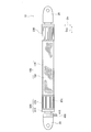
- FIG. 1 is a side view of an embodiment of a hydraulic actuator 10.
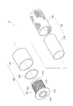
- FIG. 1 is a partially exploded perspective view of an embodiment of a hydraulic actuator 10.
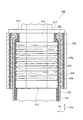
- FIG. 2 is a partial cross-sectional view of one embodiment of a tube 110.
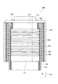
- FIG. 6 is a partial cross-sectional view of another embodiment of a tube 110.
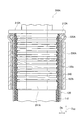
- FIG. 1 is a partial cross-sectional view taken along an axial direction D AX of a hydraulic actuator 10 including a sealing mechanism 200 according to Embodiment 1-1.
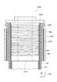
- FIG. 4 is a partial cross-sectional view along the axial direction D AX of the hydraulic actuator 10 including the sealing mechanism 200 according to Embodiment 1-2.
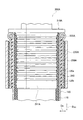
- FIG. 4 is a partial cross-sectional view along the axial direction D AX of the hydraulic actuator 10 including the sealing mechanism 200 according to Embodiment 1-3.
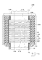
- FIG. 3 is a partial cross-sectional view along the axial direction D AX of a hydraulic actuator 10 including a sealing mechanism 200A according to Embodiment 2-1.
- FIG. 6 is a partial cross-sectional view along the axial direction D AX of the hydraulic actuator 10 including the sealing mechanism 200A according to Embodiment 2-2.
- FIG. 5 is a partial cross-sectional view along the axial direction D AX of a hydraulic actuator 10 including a sealing mechanism 200A according to Embodiment 2-3.
- FIG. 3 is a partial cross-sectional view along the axial direction D AX of a hydraulic actuator 10 including a sealing mechanism 200B according to Embodiment 3-1.
- FIG. 4 is a partial cross-sectional view along the axial direction D AX of a hydraulic actuator 10 including a sealing mechanism 200C according to Embodiment 3-2.
- FIG. 3 is a partial cross-sectional view along the axial direction D AX of a hydraulic actuator 10 including a sealing mechanism 200B according to Embodiment 3-1.
- FIG. 4 is a partial cross-sectional view along the axial direction D AX of a hydraulic actuator 10 including a sealing mechanism 200C according to Embodiment 3-2.
- FIG. 1 is a side view of a hydraulic actuator 10 according to this embodiment.
- the hydraulic actuator 10 includes an actuator body 100, a sealing mechanism 200, and a sealing mechanism 300.
- connecting portions 20 are provided at both ends of the hydraulic actuator 10.
- the actuator body 100 is composed of a tube 110 and a sleeve 120.
- the working fluid flows into the actuator body 100 through the fitting 400 and the passage hole 410.
- the actuator of the present invention is a hydraulic type, and a liquid is used as a working fluid, and examples of the liquid include oil and water.
- the actuator of the present invention may be hydraulic or hydraulic, but can be suitably used as a hydraulic because the oil resistance of the tube 110 is high.
- hydraulic oil that has been conventionally used in hydraulic drive systems can be used as the hydraulic oil.
- Actuator body portion 100 by the working fluid into the tube 110 flows, contracts in the axial direction D AX of the actuator body portion 100 expands radially D R. Further, the actuator body portion 100, by which the working fluid flows out of the tube 110, and expands in the axial direction D AX of the actuator body portion 100, to radially contract D R. Due to such a shape change of the actuator main body 100, the hydraulic actuator 10 exhibits a function as an actuator.
- Such a hydraulic actuator 10 is of a so-called McKibben type, and can be applied to artificial muscles, as well as for robot limbs (upper limbs, lower limbs, etc.) that require higher ability (contraction force). Can also be suitably used.
- a member or the like constituting the limb is connected to the connecting portion 20.
- the sealing mechanism 200 and the sealing mechanism 300 seal both ends of the actuator main body 100 in the axial direction D AX .
- the sealing mechanism 200 includes a sealing member 210 and a caulking member 230.
- the sealing member 210 seals the end of the actuator main body 100 in the axial direction D AX .
- the caulking member 230 caulks the actuator main body 100 together with the sealing member 210.
- an indentation 231 that is a trace of caulking the caulking member 230 by a jig is formed.
- the difference between the sealing mechanism 200 and the sealing mechanism 300 is whether or not the fitting 400 (and the passage hole 410) is provided.
- the fitting 400 protrudes so that a drive pressure source of the hydraulic actuator 10, specifically, a hose (pipe) connected to a working fluid compressor can be attached.
- the working fluid that has flowed in through the fitting 400 passes through the passage hole 410 and flows into the actuator body 100, specifically, the tube 110.
- FIG. 2 is a partially exploded perspective view of the hydraulic actuator 10.
- the hydraulic actuator 10 includes an actuator main body 100 and a sealing mechanism 200.
- the actuator main body 100 includes the tube 110 and the sleeve 120.
- the tube 110 is a cylindrical tubular body that expands and contracts by liquid pressure.
- the tube 110 is made of an elastic material in order to repeat contraction and expansion by the working fluid.
- the tube 110 has a laminated structure of two or more layers including a polar rubber layer and a nonpolar rubber layer.
- the content of the polar rubber having an SP value of 8.7 or more is 50% by mass or more in the rubber component, while the nonpolar rubber layer has an SP value of 8.7 or more.
- the content of polar rubber is less than 50% by mass in the rubber component.
- FIG. 3 is a partial cross-sectional view of one embodiment of the tube 110
- FIG. 4 is a partial cross-sectional view of another embodiment of the tube 110.
- Tube 110 shown in FIG. 3, the polar rubber layer 111 located on the inner surface side of the tube, adjacent the radially D R outer polar rubber layer 111, the non-polar rubber layer 112 located on the outer surface side of the tube 110 Has a two-layer structure.
- the polar rubber layer 111 has an SP value of 8.7 or more and the content of polar rubber is 50% by mass or more in the rubber component, it has excellent liquid resistance, particularly oil resistance.
- the working fluid is oil Even so, it has high durability.
- the nonpolar rubber layer 112 has a content of polar rubber having an SP value of 8.7 or more and less than 50% by mass in the rubber component, and is excellent in crack resistance, wear resistance, and slidability. It withstands a load from the side and has high durability even when it comes into contact with the sleeve 120, for example.
- the tube 110 has a laminated structure of two or more layers composed of the polar rubber layer 111 and the nonpolar rubber layer 112, a hydraulic actuator having both high liquid resistance and durability even when repeatedly expanded and contracted. realizable.
- the polar rubber layer 111 is preferably disposed on the innermost side of the tube 110.
- the oil resistance of the tube is high, and the durability of the tube 110 is further improved.
- the non-polar rubber layer 112 a radial direction D R outer polar rubber layer 111, which is preferably disposed on the outermost side of the tube 110.
- Non-polar rubber layer 112 when disposed radially D R outer polar rubber layer 111, resistance to cracking, abrasion resistance, non-polar rubber layer 112 having excellent sliding properties in the load from the sleeve 120 side
- the polar rubber layer 111 is protected, the strength of the tube 110 as a whole is improved, and the durability of the tube 110 is further improved.
- the tube 110 only needs to have a laminated structure of two or more layers composed of a polar rubber layer and a nonpolar rubber layer. For example, as shown in FIG. Then, it may have a four-layer structure).
- the polar rubber layer 111 is preferably disposed on the innermost side of the tube 110
- the nonpolar rubber layer 112 is disposed on the outermost side of the tube 110. It is preferable to arrange
- the polar rubber layer 111 By disposing the polar rubber layer 111 on the innermost side of the tube 110 that is in contact with the working fluid, the liquid rubber of the polar rubber layer 111 is sufficiently exerted, and on the outermost side of the tube 110 that is in contact with the sleeve 120, nonpolarity is provided. By disposing the rubber layer 112, the crack resistance, wear resistance, and slidability of the nonpolar rubber layer 112 are sufficiently exhibited.
- an adhesive layer is provided between the polar rubber layer and the nonpolar rubber layer, You may improve the adhesiveness between a rubber layer and a nonpolar rubber layer.
- an appropriate adhesive may be used depending on the properties of the polar rubber layer and the nonpolar rubber layer. For example, “Metaloc R-17” manufactured by Toyo Chemical Laboratory Co., Ltd. is preferably used. Can be used.
- the total thickness of the polar rubber layer 111 is preferably 10% to 90% of the total thickness of the tube 110, more preferably in the range of 20% to 80%, and the nonpolar rubber layer 112.
- the total thickness is preferably 90% to 10% of the total thickness of the tube 110, and more preferably in the range of 80% to 20%.
- the liquid resistance and durability of the tube 110 are improved, and the durability as an actuator is further improved.
- the total thickness of the tube 110 can be appropriately set according to the purpose, but is preferably in the range of 1.0 mm to 6.0 mm from the viewpoint of the durability and operation length of the actuator.
- the diameter (outer diameter) of the tube 110 can be appropriately selected according to the intended use.
- the sleeve 120 has a cylindrical shape and covers the outer peripheral surface of the tube 110.
- the sleeve 120 is a structure in which cords oriented in a predetermined direction are knitted, and the rhombus shape is repeated when the oriented cords intersect. Since the sleeve 120 has such a shape, the sleeve 120 is deformed into a pantograph and follows while restricting the contraction and expansion of the tube 110.
- polyamide fiber such as aramid fiber (aromatic polyamide fiber), polyhexamethylene adipamide (nylon 6, 6) fiber, polycaprolactam (nylon 6) fiber, polyethylene terephthalate (PET)
- PEN polyethylene naphthalate
- PEN polyethylene naphthalate
- polyurethane fibers rayon, acrylic fibers, and polyolefin fibers.
- the present invention is not limited to this type of fiber cord.
- a high-strength fiber such as PBO (polyparaphenylene benzobisoxazole) fiber or a metal cord composed of ultrafine filaments is used. Also good.
- the surface of the above-described fiber cord or metal cord may be covered with rubber, a mixture of a thermosetting resin and latex, or the like.
- the coefficient of friction on the surface of the cord can be appropriately reduced while improving the durability of the cord.
- 15 mass% or more and 50 mass% or less are preferable, and, as for the solid content rate in the mixture of a thermosetting resin and latex, 20 mass% or more and 40 mass% or less are still more preferable.
- thermosetting resins include phenol resins, resorcin resins, urethane resins, and latexes include vinylpyridine (VP) latex, styrene-butadiene rubber (SBR) latex, and acrylonitrile-butadiene rubber (NBR) latex. Etc.
- VP vinylpyridine
- SBR styrene-butadiene rubber
- NBR acrylonitrile-butadiene rubber
- the sleeve may have a single-layer structure or a multi-layer structure. In the latter case, the sleeve is wound so that the cross-section is spiral, even if the sleeves are laminated so that the cross-sections are concentric. It may be of the same structure.
- the sealing mechanism 200 seals the end of the actuator main body 100 in the axial direction D AX .
- the sealing mechanism 200 includes a sealing member 210, a first locking ring 220, and a caulking member 230.
- the sealing member 210 has a body portion 211 and a flange portion 212.
- a metal such as stainless steel can be suitably used.
- the sealing member 210 is not limited to such a metal, and a hard plastic material or the like may be used.
- the body portion 211 has a circular tubular shape, and a passage hole 215 through which the working fluid passes is formed in the body portion 211.
- the passage hole 215 communicates with the passage hole 410 (see FIG. 1).
- the tube 110 is inserted through the body portion 211.
- the flange portion 212 is continuous with the body portion 211 and is located closer to the end portion in the axial direction D AX of the hydraulic actuator 10 than the body portion 211.
- the flange portion 212 has a larger outer diameter in the radial direction D R than the body portion 211.
- the flange portion 212 locks the tube 110 and the first locking ring 220 inserted through the body portion 211.
- An uneven portion 213 is formed on the outer peripheral surface of the body portion 211.
- the uneven portion 213 contributes to suppression of slippage of the tube 110 inserted through the body portion 211. It is preferable that three or more convex portions formed by the concave and convex portions 213 are formed.
- a first small-diameter portion 214 having an outer diameter smaller than that of the trunk portion 211 is formed at a position near the flange portion 212 of the trunk portion 211.
- the shape of the first small diameter portion 214 will be further described in FIG.
- the first locking ring 220 locks the sleeve 120. Specifically, the sleeve 120 is folded radially D R outward through the first locking ring 220 (not shown in FIG. 2, see FIG. 5).
- the outer diameter of the first locking ring 220 is larger than the outer diameter of the body portion 211.
- the first locking ring 220 locks the sleeve 120 at the position of the first small diameter portion 214 of the body portion 211. That is, the first locking ring 220, a radial direction D R outside of the body 211, in a position adjacent to the flange portion 212, locking the sleeve 120.
- the first locking ring 220 Since the first locking ring 220 is locked to the first small-diameter portion 214 that is smaller than the body portion 211, the first locking ring 220 has a two-divided shape in this embodiment.
- the first locking ring 220 is not limited to being divided into two parts, and may be divided into more parts, or some of the divided parts may be rotatably connected.
- the same metal or hard plastic material as the sealing member 210 can be used.
- the caulking member 230 caulks the actuator main body 100 together with the sealing member 210.
- a metal such as an aluminum alloy, brass, or iron can be used.
- an indentation 231 as shown in FIG. 1 is formed on the caulking member 230.
- FIG. 5 is a partial cross-sectional view along the axial direction D AX of the hydraulic actuator 10 including the sealing mechanism 200 according to Embodiment 1-1.
- the sealing member 210 includes the first small diameter portion 214 having an outer diameter smaller than the outer diameter of the body portion 211.
- the first locking ring 220 is disposed in the radial direction D R outside of the first small-diameter portion 214.
- the inner diameter R1 of the first locking ring 220 is smaller than the outer diameter R3 of the body portion 211.
- the outer diameter R2 of the first locking ring 220 may also be smaller than the outer diameter R3 of the body portion 211.
- the tube 110 has a laminated structure of two or more layers including a polar rubber layer and a nonpolar rubber layer (not shown), and is inserted into the body portion 211 until it abuts against the flange portion 212.
- the sleeve 120 is folded back radially D R outward through the first locking ring 220.
- the sleeve 120 has a first folded portion 120a that is folded back via the first locking ring 220 at the end portion in the axial direction AX .
- the sleeve 120 is disposed on the outer peripheral side of the sleeve main body 120b by being folded at the sleeve main body 120b covering the outer peripheral surface of the tube 110 and the end of the sleeve main body 120b in the axial direction D AX. And a first folded portion 120a.
- First folded portion 120a is bonded to the sleeve body portion 120b located radially D R outside of the tube 110.
- an adhesive layer 240 is formed between the sleeve main body 120b and the first folded portion 120a, and the sleeve main body 120b and the first folded portion 120a are bonded by the adhesive layer 240.
- an appropriate adhesive may be used depending on the type of cord constituting the sleeve 120.
- the adhesive layer 240 is not essential, and the first folded portion 120a may not be bonded to the sleeve main body portion 120b.
- the caulking member 230 is larger than the outer diameter of the body part 211 of the sealing member 210 and is caulked by a jig after being inserted into the body part 211.
- the caulking member 230 caulks the actuator main body 100 together with the sealing member 210.
- the caulking member 230 caulks the tube 110, the sleeve main body portion 120b, and the first folded portion 120a inserted through the body portion 211. That is, the caulking member 230 caulks the tube 110, the sleeve main body portion 120b, and the first folded portion 120a together with the sealing member 210.
- FIG. 6 is a partial cross-sectional view along the axial direction D AX of the hydraulic actuator 10 including the sealing mechanism 200 according to Embodiment 1-2.
- a sheet-like elastic member is provided between the first folded portion 120 a of the sleeve 120 and the caulking member 230.
- a rubber sheet 250 is provided between the first folded portion 120a and the caulking member 230.
- the rubber sheet 250 is provided so as to cover the outer peripheral surface of the cylindrical first folded portion 120a.
- the type of the rubber sheet 250 is not particularly limited, but the same type of rubber as that of the tube 110 can be used.
- the caulking member 230 caulks the actuator main body 100 together with the sealing member 210 including the rubber sheet 250.
- FIG. 7 is a partial cross-sectional view along the axial direction D AX of the hydraulic actuator 10 including the sealing mechanism 200 according to Embodiment 1-3.
- a rubber sheet 260 is used in place of the adhesive layer 240 of Embodiment 1-1.
- the rubber sheet 260 is a sheet-like elastic member, and is provided between the sleeve main body 120b and the first folded portion 120a.
- the rubber sheet 260 the same kind of rubber as the rubber sheet 250 can be used.
- FIG. 8 is a partial cross-sectional view along the axial direction D AX of the hydraulic actuator 10 including the sealing mechanism 200A according to Embodiment 2-1.
- a sealing mechanism 200A is used instead of the sealing mechanism 200 of the first embodiment.
- the difference between the sealing mechanism 200 and the sealing mechanism 200A is that the first small-diameter portion 214 like the sealing member 210 is not formed.
- the sealing mechanism 200A includes a sealing member 210A, a first locking ring 220A, and a caulking member 230A.
- a tube 110 (not shown) having a laminated structure of two or more layers including a polar rubber layer and a nonpolar rubber layer is inserted into the body portion 211A of the sealing member 210A. Since the sealing member 210A is not formed with the first small-diameter portion 214 like the sealing member 210, the outer diameter of the first locking ring 220A is larger than the outer diameter of the body portion 211A. For this reason, the first locking ring 220A is locked by the flange portion 212A and the caulking member 230A.
- the caulking member 230A does not come into contact with the flange portion 212A. That is, the portion of the first locking ring 220A where the sleeve 120 is folded back is exposed to the outside. Furthermore, since the outer diameter of the first locking ring 220A is larger than the outer diameter of the body portion 211A, it may not be divided like the first locking ring 220 of the first embodiment.
- an adhesive layer 240 is formed between the sleeve main body 120b and the first folded portion 120a, as in the case of the embodiment 1-1.
- FIG. 9 is a partial cross-sectional view along the axial direction D AX of the hydraulic actuator 10 including the sealing mechanism 200A according to Embodiment 2-2.
- a sheet-like elastic member is provided between the first folded portion 120a of the sleeve 120 and the caulking member 230A.
- a rubber sheet 250A is provided between the first folded portion 120a and the caulking member 230A. Similar to the rubber sheet 250 of Embodiment 1-2, the rubber sheet 250A is provided so as to cover the outer peripheral surface of the cylindrical first folded portion 120a.
- FIG. 10 is a partial cross-sectional view along the axial direction D AX of the hydraulic actuator 10 including the sealing mechanism 200A according to Embodiment 2-3.
- a rubber sheet 260 is used instead of the adhesive layer 240 of the embodiment 2-1.
- the rubber sheet 260 is a sheet-like elastic member as in the embodiment 1-3, and is provided between the sleeve main body 120b and the first folded portion 120a.
- FIG. 11 is a partial cross-sectional view along the axial direction D AX of the hydraulic actuator 10 including the sealing mechanism 200B according to Embodiment 3-1.
- Embodiment 3 (3-1 and 3-2) two locking rings are used.
- the sealing mechanism 200B includes a sealing member 210B, a first locking ring 220B, a caulking member 230B, and a second locking ring 270.
- the sealing mechanism 200B includes the second locking ring 270 in addition to the first locking ring 220B.
- the second locking ring 270 a radial direction D R outside of the body 211B, at a position on the center side in the axial direction D AX of the actuator body portion 100 than the first locking ring 220B, locking the sleeve 120 To do.
- the sealing member 210B has a second small diameter portion 216B having an outer diameter smaller than the outer diameter of the body portion 211B.
- the second locking ring 270 is disposed in the radial direction D R outside of the second small diameter portion 216B.
- the inner diameter of the second locking ring 270 is preferably smaller than the outer diameter of the body portion 211B.
- the outer diameter of the second locking ring 270 may be smaller than the outer diameter of the body portion 211B.
- the sleeve 120 includes a second folded portion 120 c that is folded back via the second locking ring 270.
- the second folded portion 120c is continuous with the first folded portion 120a. That is, the second folded portion 120c is folded at the end portion of the first folded portion 120a in the axial direction D AX and arranged on the outer peripheral side of the first folded portion 120a.
- the sleeve 120 is folded back toward the center in the axial direction D AX of the actuator main body 100 via the first locking ring 220B, thereby forming the first folded portion 120a.
- the sleeve 120 forms a second folded portion 120 c by folding the first folded portion 120 a toward the end of the actuator main body 100 in the axial direction D AX .
- the tube 110 is inserted into the body portion 211B, the sleeve body 120b located radially D R outer tube 110, a first folded portion 120a, and a second folded portion 120c, or with a sealing member 210B Close.
- a rubber sheet 260 similar to that of Embodiment 1-3 is provided between the sleeve body 120b and the first folded portion 120a.
- a sheet-like elastic member is provided between the first folded portion 120a and the second folded portion 120c.
- a rubber sheet 280 is provided between the first folded portion 120a and the second folded portion 120c. The rubber sheet 280 is provided so as to cover the outer peripheral surface of the cylindrical first folded portion 120a.
- a rubber sheet 290 having substantially the same shape as the rubber sheet 250 of the embodiment 1-3 is provided between the second folded portion 120c and the caulking member 230B.
- the rubber sheet 290 is provided so as to cover the outer peripheral surface of the cylindrical second folded portion 120c.
- FIG. 12 is a partial cross-sectional view along the axial direction D AX of the hydraulic actuator 10 including the sealing mechanism 200C according to Embodiment 3-2.
- FIG. 12 is a partial cross-sectional view along the axial direction D AX of the hydraulic actuator 10 including the sealing mechanism 200C according to Embodiment 3-2.
- differences from the embodiment 3-1 will be mainly described.
- Embodiment 3-2 a sealing member 210C in which the first small diameter portion 214B and the second small diameter portion 216B are not formed is used.
- the sealing member 210C has a body portion 211C. Since the sealing member 210C is not formed with the first small diameter portion 214B and the second small diameter portion 216B as in the sealing member 210B, the inner diameter of the first locking ring 220C and the inner diameter of the second locking ring 270C are The outer diameter of the body portion 211C is larger.
- the caulking member 230C is located between the first locking ring 220C and the second locking ring 270C in the axial direction D AX . That is, the portion of the first locking ring 220C and the portion of the second locking ring 270C where the sleeve 120 is folded back are exposed to the outside.
- a rubber sheet 281 having substantially the same shape as the rubber sheet 280 of the embodiment 3-1 is provided between the first folded portion 120a and the second folded portion 120c.
- a rubber sheet 291 having substantially the same shape as the rubber sheet 290 of the embodiment 3-1 is provided between the second folded portion 120c of the sleeve 120 and the caulking member 230C.
- the tube 110 has a polar rubber layer 111 in which the content of polar rubber having an SP value of 8.7 or more and 50% by mass or more in the rubber component and a polarity having an SP value of 8.7 or more. It has a laminated structure of two or more layers composed of the nonpolar rubber layer 112 whose rubber content is less than 50% by mass in the rubber component.
- the polar rubber having an SP value of 8.7 or more is not particularly limited, and examples thereof include acrylonitrile-butadiene rubber (NBR, also referred to as “nitrile rubber”), hydrogenated acrylonitrile-butadiene rubber (hydrogenated). NBR, “hydrogenated nitrile rubber”), chloroprene rubber (CR), epichlorohydrin rubber, and the like. These polar rubbers may be used alone or in a blend of two or more.
- the polar rubber layer 111 preferably contains acrylonitrile-butadiene rubber and / or hydrogenated acrylonitrile butadiene rubber.
- acrylonitrile-butadiene rubber and hydrogenated acrylonitrile butadiene rubber have particularly high oil resistance and excellent workability. Therefore, when the polar rubber layer 111 contains acrylonitrile-butadiene rubber and / or hydrogenated acrylonitrile butadiene rubber, the oil resistance of the polar rubber layer 111 is further improved.
- the acrylonitrile-butadiene rubber and the hydrogenated acrylonitrile butadiene rubber preferably have a nitrile content, that is, an acrylonitrile unit content of 20% by mass to 50% by mass because oil resistance is further improved.
- the acrylonitrile-butadiene rubber and / or hydrogenated acrylonitrile butadiene rubber is generally a low nitrile type having an acrylonitrile unit content of less than 25% by mass, and a medium nitrile type having an acrylonitrile content of 25% by mass to less than 35% by mass.
- the acrylonitrile unit content is classified as a high nitrile type having a content of 35% by mass or more.
- the acrylonitrile-butadiene rubber and / or hydrogenated acrylonitrile butadiene rubber preferably includes two or more kinds of acrylonitrile-butadiene rubber and / or hydrogenated acrylonitrile butadiene rubber having different acrylonitrile unit contents.
- a desired nitrile content can be easily achieved.
- the content of the acrylonitrile-butadiene rubber (NBR) and hydrogenated acrylonitrile butadiene rubber (hydrogenated NBR) in the rubber component of the polar rubber layer 111 is preferably 50 to 100% by mass, and preferably 60 to 90% by mass. It is more preferable that
- Hydrogenated acrylonitrile-butadiene rubber is obtained by adding hydrogen to acrylonitrile-butadiene rubber.
- Hydrogenated acrylonitrile-butadiene rubber is usually preferred in that it has oil resistance similar to that of acrylonitrile-butadiene rubber and is superior in heat resistance and the like compared to acrylonitrile-butadiene rubber.
- Chloroprene rubber is preferable among the polar rubbers in terms of excellent mechanical properties such as tensile strength and elongation, and processability.
- Epichlorohydrin rubber is preferable among the polar rubbers because it is excellent in ozone resistance and adhesiveness.
- the content of the polar rubber having an SP value of 8.7 or more is 50% by mass or more, preferably 60 to 100% by mass, more preferably 60 to 95% by mass in the rubber component.
- the nonpolar rubber layer 112 has a content of polar rubber having an SP value of 8.7 or more in the rubber component of less than 50% by mass, preferably 0 to 10% by mass.
- the content of the polar rubber in the nonpolar rubber layer 112 is within this range, the content of the nonpolar rubber having an SP value of less than 8.7 can be increased.
- the rubber component preferably has a weighted average nitrile content of 20% by mass or more and 45% by mass or less.
- the oil resistance of the polar rubber layer 111 is further improved, and the durability of the tube is further improved.
- the polar rubber layer 111 and the nonpolar rubber layer 112 are rubber components other than the polar rubber having an SP value of 8.7 or more, for example, a nonpolar diene rubber having an SP value of less than 8.7. May be included.
- BR butadiene rubber
- VC-BR vinyl cis-polybutadiene rubber
- VC-BR is a rubber composed of polybutadiene having a cis-1,4 structure as a repeating unit and polybutadiene having a 1,2-vinyl structure as a repeating unit.
- the ratio of the cis-1,4 structure in the microstructure other than the 1,2-vinyl structure of VC-BR is usually 97% by mass or more.
- the non-polar rubber layer 112 contains other rubber components because the content of the polar rubber having the SP value of 8.7 or more is less than 50% by mass in the rubber component. Examples thereof include butadiene rubber (BR), natural rubber (NR), synthetic isoprene rubber (IR), styrene-butadiene rubber (SBR), and butyl rubber. When the nonpolar rubber layer 112 contains these other rubber components, the crack resistance, wear resistance, and slidability of the nonpolar rubber layer 112 are improved, and the durability of the tube is further improved.
- BR butadiene rubber
- NR natural rubber
- IR synthetic isoprene rubber
- SBR styrene-butadiene rubber
- butyl rubber butyl rubber
- the polar rubber layer 111 and the nonpolar rubber layer 112 are made of at least one material selected from the group consisting of polyvinyl chloride (PVC), zinc polyacrylate, and aliphatic resin in addition to the rubber component described above. It is preferable to add in accordance with the above. When the polar rubber layer and the nonpolar rubber layer contain these materials, the mechanical strength of the tube is improved. Examples of the aliphatic resin include polyolefin resins.
- the polar rubber layer 111 and the nonpolar rubber layer 112 may further contain other compounding agents in addition to the rubber component described above.
- other compounding agents include carbon black, silica, zinc white, stearic acid, anti-aging agent, plasticizer, sulfur, scorch inhibitor, vulcanization accelerator, and organic peroxide.
- the polar rubber layer 111 and the nonpolar rubber layer 112 preferably contain carbon black.
- the carbon black content is preferably in the range of 5 to 70 parts by weight, more preferably in the range of 30 to 70 parts by weight, and still more preferably in the range of 40 to 60 parts by weight with respect to 100 parts by weight of the rubber component.
- the carbon black content in the polar rubber layer 111 is preferably in the range of 5 to 50 parts by mass, more preferably 5 to 45 parts by mass, with respect to 100 parts by mass of the rubber component in the polar rubber layer 111.
- the range of 5 to 30 parts by mass is more preferable. If the content of carbon black in the polar rubber layer 111 is 5 parts by mass or more with respect to 100 parts by mass of the rubber component, the strength of the tube 110 is further improved, and the durability of the tube 110 is further improved. If it is 50 parts by mass or less, since the elongation (Eb) at the time of cutting of the tube 110 is increased, the durability of the tube 110 is further improved. Further, the carbon black content in the nonpolar rubber layer 112 is preferably in the range of 5 to 70 parts by weight, and 25 to 50 parts by weight with respect to 100 parts by weight of the rubber component rubber component in the nonpolar rubber layer 112. The range of is more preferable.
- the carbon black is not particularly limited, and examples thereof include GPF, FEF, HAF, ISAF, and SAF grade carbon black. These carbon blacks may be used alone or in combination of two or more.
- Carbon black contained in the non-polar rubber layer 112 is preferably a nitrogen adsorption specific surface area of 34m 2 / g ⁇ 155m 2 / g, is preferably 40m 2 / g ⁇ 155m 2 / g, 70m 2 / More preferably, it is g to 145 m 2 / g.
- the nitrogen adsorption specific surface area of carbon black contained in the nonpolar rubber layer 112 is within this range, the crack resistance, wear resistance, and slidability of the nonpolar rubber layer 112 are further improved.
- the carbon black contained in the polar rubber layer 111 is not particularly limited, but preferably has a nitrogen adsorption specific surface area of 70 m 2 / g to 145 m 2 / g. If the nitrogen adsorption specific surface area of carbon black contained in the polar rubber layer 111 is within this range, the strength of the polar rubber layer 111 is further improved.
- the polar rubber layer 111 further contains silica, and the content of the silica is preferably 5 to 20 parts by mass with respect to 100 parts by mass of the rubber component in the polar rubber layer 111. More preferably. Since the content of silica in the polar rubber layer 111 is 5 parts by mass or more with respect to 100 parts by mass of the rubber component, the strength of the tube 110 is improved, and the crack resistance of the tube 110 is improved, By being 20 mass parts or less, crack progress property can further be improved.
- the silica is not particularly limited, and examples thereof include wet silica (hydrous silicic acid), dry silica (anhydrous silicic acid), calcium silicate, aluminum silicate, and the like. Among these, wet silica is preferable. These silicas may be used alone or in combination of two or more.
- the polar rubber layer 111 may further contain a silane coupling agent, but the content of the silane coupling agent is preferably 0.1 parts by mass or less with respect to 100 parts by mass of the silica.
- the polar rubber layer may not contain a silane coupling agent, that is, the content of the silane coupling agent is preferably in the range of 0 to 0.1 parts by mass with respect to 100 parts by mass of the silica.
- the content of the silane coupling agent is preferably as small as possible. And if content of a silane coupling agent is 0.1 mass part or less with respect to 100 mass parts of silica, when a strain is applied, when a rubber component is peeled off from the silica surface, energy loss occurs. And crack propagation resistance is further improved. Therefore, it is particularly preferable that the polar rubber layer does not contain a silane coupling agent.
- the nonpolar rubber layer 112 preferably further contains silica.
- the content of silica is preferably in the range of 10 to 30 parts by mass, more preferably in the range of 15 to 25 parts by mass with respect to 100 parts by mass of the rubber component.
- silica wet silica (hydrous silicic acid), dry-type silica (anhydrous silicic acid), calcium silicate, aluminum silicate etc. are mentioned, Among these, wet silica is preferable.
- These silicas may be used alone or in combination of two or more.
- the nonpolar rubber layer 112 when the nonpolar rubber layer 112 contains silica, the nonpolar rubber layer 112 preferably further contains a silane coupling agent.
- the nonpolar rubber layer 112 contains a silane coupling agent together with silica, the strength of the nonpolar rubber layer 112 is improved and the durability of the tube 110 is improved.
- the compounding amount of the silane coupling agent is preferably in the range of 1 to 15 parts by mass, more preferably in the range of 2 to 10 parts by mass with respect to 100 parts by mass of the silica.
- the silane coupling agent is not particularly limited, and examples thereof include bis (3-triethoxysilylpropyl) tetrasulfide, bis (3-triethoxysilylpropyl) trisulfide, bis (3-triethoxysilylpropyl) disulfide, Bis (2-triethoxysilylethyl) tetrasulfide, bis (3-trimethoxysilylpropyl) tetrasulfide, bis (2-trimethoxysilylethyl) tetrasulfide, 3-mercaptopropyltrimethoxysilane, 3-mercaptopropyltriethoxy Silane, 2-mercaptoethyltrimethoxysilane, 2-mercaptoethyltriethoxysilane, 3-trimethoxysilylpropyl-N, N-dimethylthiocarbamoyl tetrasulfide, 3-triethoxysilylpropyl
- anti-aging agent examples include N-phenyl-N′1,3-diphenylbutyl-p-phenylenediamine and N-phenyl-N ′-(1,3-dimethylbutyl) -p-phenylenediamine.
- examples of the plasticizer include oil, etc.
- examples of the scorch inhibitor include N-cyclohexylthiophthalimide
- examples of the vulcanization accelerator include N-cyclohexyl- Examples include 2-benzothiazolylsulfenamide (CBS), 1,3-diphenylguanidine (DPG), tetrakis (2-ethylhexyl) thiuram disulfide (TOT), di-2-benzothiazolyl disulfide (MBTS), and the like.
- CBS 2-benzothiazolylsulfenamide
- DPG 1,3-diphenylguanidine
- TOT tetrakis (2-ethylhexyl) thiuram disulfide
- MBTS di-2-benzothiazolyl disulfide
- the polar rubber layer 111 preferably has an elongation at break (Eb) of 500% or more, more preferably 800% or more, and still more preferably 1000% or more.
- Eb elongation at break
- the elongation at break (Eb) is a value measured according to JIS K 6251.
- the nonpolar rubber layer 112 preferably has a tensile stress (M100) at 100% elongation of 1.0 MPa or more, more preferably 1.5 MPa or more, and 5.0 MPa or less. preferable.
- M100 tensile stress
- the nonpolar rubber layer 112 having a tensile stress (M100) at 100% elongation of 1.0 MPa or more, even if the elongation (Eb) at the time of cutting of the polar rubber layer 111 is 500% or more, excessive expansion is caused. Therefore, the durability of the actuator can be further improved.
- the tensile stress (M100) at 100% elongation is 5.0 MPa or less, the operability of the actuator is high.
- the tube 110 having a laminated structure composed of the polar rubber layer 111 and the nonpolar rubber layer 112 includes, for example, a rubber composition for the polar rubber layer and a rubber composition for the nonpolar rubber layer by blending a compounding agent with the rubber component described above.
- a rubber composition can be prepared, and these rubber compositions can be used for coextrusion with an extruder.
- Anti-aging agent “NOCRACK 6C” manufactured by Ouchi Shinsei Chemical Co., Ltd. * 14 Resin: “Clayton 100” manufactured by Nippon Zeon Co., Ltd. * 15 Silica: “Nipsil AQ” manufactured by Tosoh Silica Corporation * 16 Silane coupling agent: “Si69” manufactured by Evonic * 17 Plasticizer: “Sanso Sizer DOA” manufactured by Shin Nippon Rika Co., Ltd. * 18 Zinc flower: ZnO, "Zinc flower No. 3" manufactured by Hakusui Chemical Co., Ltd. * 19 Sulfur: “Sulfax Z” manufactured by Tsurumi Chemical Co., Ltd.
- Vulcanization accelerator 1 Vulcanization accelerator CBS, “Noxeller CZ” manufactured by Ouchi Shinsei Chemical Co., Ltd. * 21 Vulcanization accelerator 2: Vulcanization accelerator DPG, “Noxeller D” manufactured by Ouchi Shinsei Chemical Co., Ltd. * 22 Vulcanization accelerator 3: Vulcanization accelerator TOT, “Noxeller TOT-N” manufactured by Ouchi Shinsei Chemical Co., Ltd. * 23 Vulcanization accelerator 4: Vulcanization accelerator MTBS, “Noxeller DM” manufactured by Ouchi Shinsei Chemical Co., Ltd. * 24 Vulcanization accelerator 5: Vulcanization accelerator DPG, “Soccinol DZ” manufactured by Sumitomo Chemical Co., Ltd.
- An actuator having the structure shown in FIGS. 1 and 2 was manufactured using the tube and the mesh-like sleeve. Note that the length between the sealing mechanism 200 and the sealing mechanism 300 is 250 mm.
- As the hydraulic fluid for the tube incorporated in the actuator UF46 manufactured by Cosmo Super Epoch Co., Ltd. was used. The durability of the manufactured actuator was evaluated by the following method. The results are shown in Tables 3-4.
- the hydraulic actuator according to the present invention has high durability. Further, from Table 4, when the polar rubber layer contains silica and the silica content is 5 to 20 parts by mass with respect to 100 parts by mass of the rubber component in the polar rubber layer, the durability of the hydraulic actuator is further improved. It turns out that it improves.
Landscapes
- Engineering & Computer Science (AREA)
- Physics & Mathematics (AREA)
- Fluid Mechanics (AREA)
- Mechanical Engineering (AREA)
- General Engineering & Computer Science (AREA)
- Chemical & Material Sciences (AREA)
- Analytical Chemistry (AREA)
- Actuator (AREA)
Abstract
本発明の課題は、チューブの耐久性を向上させた液圧式アクチュエータを提供することであり、その解決手段は、液圧によって膨張及び収縮する筒状のチューブ(110)と、所定方向に配向されたコードを編み込んだ筒状のスリーブ(120)と、によって構成されるアクチュエータ本体部(100)を具え、前記チューブ(110)は、SP値が8.7以上である極性ゴムの含有率がゴム成分中50質量%以上である極性ゴム層(111)及びSP値が8.7以上である極性ゴムの含有率がゴム成分中50質量%未満である非極性ゴム層(112)からなる2層以上の積層構造を有することを特徴とする、液圧式アクチュエータ(10)である。
Description
本発明は、液圧式アクチュエータに関するものである。
従来、チューブを膨張及び収縮させるアクチュエータとしては、作動流体として空気を用いて膨張、収縮するゴム製のチューブ(管状体)と、チューブの外周面を覆うスリーブ(網組補強構造)と、を有する空気圧式アクチュエータ(いわゆるマッキベン型)が広く用いられている(例えば、特許文献1を参照)。
チューブ及びスリーブによって構成されるアクチュエータ本体部の両端は、金属で形成された封止部材を用いてかしめられる。
スリーブは、ポリアミド繊維などの高張力繊維または金属のコードを編み込んだ筒状の構造体であり、チューブの膨張運動を所定範囲に規制する。
このような空気圧式アクチュエータは、様々な分野で用いられているが、特に、介護・福祉用機器の人工筋肉として好適に用いられている。
しかしながら、前述した従来のアクチュエータは、作動流体として空気を用いているため、強度(耐圧力)が必ずしも高くなく、例えば、最大で0.5MPa程度の耐圧力しかなかった。
ここで、作動流体として、油や水等の液体を用いる液圧式アクチュエータでは、例えば50MPaという高い圧力が印加されるため、従来のアクチュエータでは、耐久性が十分ではない。特に、従来のアクチュエータでは、繰り返される伸縮動作により、スリーブに接するチューブに負荷がかかり、チューブの耐久性に改善の余地がある。
そこで、本発明は、上記従来技術の問題を解決し、作動流体として液体を用いるアクチュエータにおいて、チューブの耐久性を向上させた液圧式アクチュエータを提供することを課題とする。
上記課題を解決する本発明の要旨構成は、以下の通りである。
本発明の液圧式アクチュエータは、液圧によって膨張及び収縮する筒状のチューブと、所定方向に配向されたコードを編み込んだ筒状の構造体であって前記チューブの外周面を覆うスリーブと、によって構成されるアクチュエータ本体部を具え、
前記チューブは、SP値が8.7以上である極性ゴムの含有率がゴム成分中50質量%以上である極性ゴム層及びSP値が8.7以上である極性ゴムの含有率がゴム成分中50質量%未満である非極性ゴム層からなる2層以上の積層構造を有することを特徴とする。
かかる本発明の液圧式アクチュエータは、チューブの耐久性が向上しており、アクチュエータとしての耐久性が高い。
前記チューブは、SP値が8.7以上である極性ゴムの含有率がゴム成分中50質量%以上である極性ゴム層及びSP値が8.7以上である極性ゴムの含有率がゴム成分中50質量%未満である非極性ゴム層からなる2層以上の積層構造を有することを特徴とする。
かかる本発明の液圧式アクチュエータは、チューブの耐久性が向上しており、アクチュエータとしての耐久性が高い。
なお、本発明において、極性ゴム、非極性ゴム等のゴム成分のSP値(溶解パラメーター)は、Fedors法に従って、算出し、その単位は「(cal/cm3)1/2」とする。
そして、本発明においては、SP値が8.7以上であるゴムを「極性ゴム」と定義し、SP値が8.7未満であるゴムを「非極性ゴム」と定義する。
また、本発明においては、SP値が8.7以上である極性ゴムの含有率がゴム成分中50質量%以上であるゴム層を「極性ゴム層」と定義し、SP値が8.7以上である極性ゴムの含有率がゴム成分中50質量%未満であるゴム層を「非極性ゴム層」と定義する。
そして、本発明においては、SP値が8.7以上であるゴムを「極性ゴム」と定義し、SP値が8.7未満であるゴムを「非極性ゴム」と定義する。
また、本発明においては、SP値が8.7以上である極性ゴムの含有率がゴム成分中50質量%以上であるゴム層を「極性ゴム層」と定義し、SP値が8.7以上である極性ゴムの含有率がゴム成分中50質量%未満であるゴム層を「非極性ゴム層」と定義する。
本発明の液圧式アクチュエータの好適例においては、前記極性ゴム層が、前記チューブの最内側に配置されている。この場合、チューブの耐油性が向上し、チューブの耐久性が更に向上する。
本発明の液圧式アクチュエータの他の好適例においては、前記非極性ゴム層が、前記極性ゴム層の径方向外側であって、前記チューブの最外側に配置されている。この場合、チューブの強度が向上し、チューブの耐久性が更に向上する。
本発明の液圧式アクチュエータの他の好適例においては、前記極性ゴム層が、アクリロニトリル-ブタジエンゴムおよび/または水素化アクリロニトリルブタジエンゴムを含む。この場合、極性ゴム層の耐油性が向上し、チューブの耐久性が更に向上する。
ここで、前記アクリロニトリル-ブタジエンゴムおよび/または水素化アクリロニトリルブタジエンゴムは、アクリロニトリル単位の含有量が20質量%~50質量%であることが好ましい。この場合、極性ゴム層の耐油性が更に向上し、チューブの耐久性が更に向上する。
また、前記アクリロニトリル-ブタジエンゴムおよび/または水素化アクリロニトリルブタジエンゴムは、アクリロニトリル単位の含有量が異なる2種類以上のアクリロニトリル-ブタジエンゴムおよび/または水素化アクリロニトリルブタジエンゴムを含むことが好ましい。この場合、極性ゴム層中のアクリロニトリル単位の含有量を所望の値に調整し易い。
本発明の液圧式アクチュエータにおいて、前記極性ゴム層は、更にSP値が8.7未満である非極性ジエン系ゴムを含むことが好ましい。この場合、極性ゴム層の強度が向上し、チューブの耐久性が更に向上する。
本発明の液圧式アクチュエータにおいて、前記極性ゴム層は、前記ゴム成分の加重平均ニトリル含量が20%以上45%以下であることが好ましい。この場合、極性ゴム層の耐油性が更に向上し、チューブの耐久性が更に向上する。
本発明の液圧式アクチュエータの他の好適例においては、前記非極性ゴム層が、ブタジエンゴム、天然ゴム、合成イソプレンゴム、スチレン-ブタジエンゴム、ブチルゴムからなる群から選択される1種類以上を含む。この場合、非極性ゴム層の強度が向上し、チューブの耐久性が更に向上する。
本発明の液圧式アクチュエータの他の好適例においては、前記極性ゴム層及び前記非極性ゴム層が、カーボンブラックを含む。この場合、極性ゴム層及び非極性ゴム層の強度が向上し、チューブの耐久性が更に向上する。
ここで、前記非極性ゴム層に含まれるカーボンブラックは、窒素吸着比表面積が34m2/g~155m2/gであることが好ましい。この場合、非極性ゴム層の強度が更に向上し、チューブの耐久性が更に向上する。
なお、本発明において、カーボンブラックの窒素吸着比表面積(N2SA)は、JIS K6217-2:2001に従って測定する。
なお、本発明において、カーボンブラックの窒素吸着比表面積(N2SA)は、JIS K6217-2:2001に従って測定する。
本発明の液圧式アクチュエータの他の好適例においては、前記非極性ゴム層が、更にシリカを含む。この場合、非極性ゴム層の強度が更に向上し、チューブの耐久性が更に向上する。
ここで、前記非極性ゴム層は、更にシランカップリング剤を含むことが好ましい。この場合、非極性ゴム層の強度が更に向上し、チューブの耐久性が更に向上する。
本発明の液圧式アクチュエータの他の好適例においては、前記極性ゴム層が、更にシリカを含み、該シリカの含有量が、当該極性ゴム層中のゴム成分100質量部に対して5~20質量部である。この場合、チューブの耐亀裂進展性が向上し、アクチュエータとしての耐久性が更に向上する。
ここで、前記極性ゴム層が、更に、前記シリカ100質量部に対して、シランカップリング剤を0.1質量部以下含むことが好ましい。この場合、チューブの耐亀裂進展性が更に向上する。
本発明の液圧式アクチュエータの他の好適例においては、前記極性ゴム層の厚みが、前記チューブの総厚みの10%~90%であり、前記非極性ゴム層の厚みが、前記チューブの総厚みの90%~10%である。この場合、チューブの耐久性が更に向上する。
本発明の液圧式アクチュエータにおいて、前記非極性ゴム層は、100%伸長時の引張応力(M100)が1.0MPa以上であることが好ましい。この場合、アクチュエータの耐久性を更に向上させることができる。
なお、本発明において、前記100%伸長時の引張応力(M100)は、JIS K 6251に従って測定した値である。
なお、本発明において、前記100%伸長時の引張応力(M100)は、JIS K 6251に従って測定した値である。
本発明によれば、チューブの耐久性を向上させた液圧式アクチュエータを提供することができる。
以下に、本発明の液圧式アクチュエータを、その実施形態に基づき、図面を参照しつつ、詳細に例示説明する。なお、同一の機能や構成には、同一または類似の符号を付して、その説明を適宜省略する。
(1)液圧式アクチュエータの全体概略構成
図1は、本実施形態に係る液圧式アクチュエータ10の側面図である。図1に示すように、液圧式アクチュエータ10は、アクチュエータ本体部100、封止機構200及び封止機構300を具える。また、液圧式アクチュエータ10の両端には、連結部20がそれぞれ設けられる。
図1は、本実施形態に係る液圧式アクチュエータ10の側面図である。図1に示すように、液圧式アクチュエータ10は、アクチュエータ本体部100、封止機構200及び封止機構300を具える。また、液圧式アクチュエータ10の両端には、連結部20がそれぞれ設けられる。
アクチュエータ本体部100は、チューブ110とスリーブ120とによって構成される。アクチュエータ本体部100には、フィッティング400及び通過孔410を介して作動流体が流入する。ここで、本発明のアクチュエータは、液圧式であり、作動流体として液体が用いられ、該液体としては、油や水等が挙げられる。なお、本発明のアクチュエータは、油圧式でも、水圧式でもよいが、チューブ110の耐油性が高いため、油圧式として、好適に使用できる。また、油圧式の場合、作動油としては、従来より油圧駆動システムに使用されている作動油を使用することができる。
アクチュエータ本体部100は、チューブ110内へ作動流体が流入することによって、アクチュエータ本体部100の軸方向DAXに収縮し、径方向DRに膨張する。また、アクチュエータ本体部100は、チューブ110から作動流体が流出することによって、アクチュエータ本体部100の軸方向DAXに膨張し、径方向DRに収縮する。このようなアクチュエータ本体部100の形状変化によって、液圧式アクチュエータ10は、アクチュエータとしての機能を発揮する。
また、このような液圧式アクチュエータ10は、いわゆるマッキベン型であり、人工筋肉用として適用できることは勿論のこと、より高い能力(収縮力)が要求されるロボットの体肢(上肢や下肢など)用としても好適に用い得る。連結部20には、当該体肢を構成する部材などが連結される。
封止機構200及び封止機構300は、軸方向DAXにおけるアクチュエータ本体部100の両端部を封止する。具体的には、封止機構200は、封止部材210及びかしめ部材230を含む。封止部材210は、アクチュエータ本体部100の軸方向DAXの端部を封止する。また、かしめ部材230は、アクチュエータ本体部100を封止部材210と共にかしめる。かしめ部材230の外周面には、治具によってかしめ部材230がかしめられた痕である圧痕231が形成される。
封止機構200と封止機構300との相違点は、フィッティング400(及び通過孔410)が設けられているか否かである。
フィッティング400は、液圧式アクチュエータ10の駆動圧力源、具体的には、作動流体のコンプレッサと接続されたホース(管路)を取り付けられるように突出している。フィッティング400を介して流入した作動流体は、通過孔410を通過してアクチュエータ本体部100の内部、具体的には、チューブ110の内部に流入する。
フィッティング400は、液圧式アクチュエータ10の駆動圧力源、具体的には、作動流体のコンプレッサと接続されたホース(管路)を取り付けられるように突出している。フィッティング400を介して流入した作動流体は、通過孔410を通過してアクチュエータ本体部100の内部、具体的には、チューブ110の内部に流入する。
図2は、液圧式アクチュエータ10の一部分解斜視図である。図2に示すように、液圧式アクチュエータ10は、アクチュエータ本体部100及び封止機構200を具える。
アクチュエータ本体部100は、前述したように、チューブ110とスリーブ120とによって構成される。
アクチュエータ本体部100は、前述したように、チューブ110とスリーブ120とによって構成される。
チューブ110は、液圧によって膨張及び収縮する円筒状の筒状体である。チューブ110は、作動流体による収縮及び膨張を繰り返すため、弾性材料からなり、そして、本発明においては、チューブ110は、極性ゴム層及び非極性ゴム層からなる2層以上の積層構造を有する。ここで、極性ゴム層は、SP値が8.7以上である極性ゴムの含有率がゴム成分中50質量%以上であり、一方、非極性ゴム層は、SP値が8.7以上である極性ゴムの含有率がゴム成分中50質量%未満である。
図3は、チューブ110の一実施形態の部分断面図であり、図4は、チューブ110の他の実施形態の部分断面図である。
図3に示すチューブ110は、チューブの内面側に位置する極性ゴム層111と、該極性ゴム層111の径方向DR外側に隣接して、チューブ110の外面側に位置する非極性ゴム層112とからなる2層構造を有する。
図3に示すチューブ110は、チューブの内面側に位置する極性ゴム層111と、該極性ゴム層111の径方向DR外側に隣接して、チューブ110の外面側に位置する非極性ゴム層112とからなる2層構造を有する。
極性ゴム層111は、SP値が8.7以上である極性ゴムの含有率がゴム成分中50質量%以上であるため、耐液性、特には、耐油性に優れ、例えば、作動流体が油であっても、高い耐久性を有する。
一方、非極性ゴム層112は、SP値が8.7以上である極性ゴムの含有率がゴム成分中50質量%未満であり、耐亀裂性、耐摩耗性、摺動性に優れ、スリーブ120側からの負荷に耐え、例えば、スリーブ120と接触しても、高い耐久性を有する。
そのため、チューブ110が、極性ゴム層111及び非極性ゴム層112からなる2層以上の積層構造を有することで、繰り返し伸縮しても、高い耐液性と耐久性を兼ね備えた、液圧式アクチュエータを実現できる。
本発明においては、極性ゴム層111が、チューブ110の最内側に配置されていることが好ましい。極性ゴム層111が、チューブ110の最内側に配置されている場合、チューブの耐油性が高く、チューブ110の耐久性が更に向上する。
また、本発明においては、非極性ゴム層112が、極性ゴム層111の径方向DR外側であって、チューブ110の最外側に配置されていることが好ましい。非極性ゴム層112が、極性ゴム層111の径方向DR外側に配置されている場合、耐亀裂性、耐摩耗性、摺動性に優れる非極性ゴム層112がスリーブ120側からの負荷に耐えることによって、極性ゴム層111が保護され、チューブ110全体としての強度が向上し、チューブ110の耐久性が更に向上する。
なお、本発明において、チューブ110は、極性ゴム層及び非極性ゴム層からなる2層以上の積層構造を有すればよく、例えば、図4に示すように、3層以上の積層構造(図4では、4層構造)を有してもよい。
ここで、チューブ110が3層以上の積層構造を有する場合、極性ゴム層111が、チューブ110の最内側に配置されていることが好ましく、また、非極性ゴム層112が、チューブ110の最外側に配置されていることが好ましい。作動流体に接するチューブ110の最内側に、極性ゴム層111を配置することで、極性ゴム層111の耐液性が十分に発揮され、また、スリーブ120に接するチューブ110の最外側に、非極性ゴム層112を配置することで、非極性ゴム層112の耐亀裂性、耐摩耗性、摺動性が十分に発揮される。
ここで、チューブ110が3層以上の積層構造を有する場合、極性ゴム層111が、チューブ110の最内側に配置されていることが好ましく、また、非極性ゴム層112が、チューブ110の最外側に配置されていることが好ましい。作動流体に接するチューブ110の最内側に、極性ゴム層111を配置することで、極性ゴム層111の耐液性が十分に発揮され、また、スリーブ120に接するチューブ110の最外側に、非極性ゴム層112を配置することで、非極性ゴム層112の耐亀裂性、耐摩耗性、摺動性が十分に発揮される。
図3及び図4に示すチューブ110は、極性ゴム層111と非極性ゴム層112のみからなるが、本発明においては、極性ゴム層と非極性ゴム層との間に接着層を設けて、極性ゴム層と非極性ゴム層との間の接着性を向上させてもよい。ここで、接着層には、極性ゴム層と非極性ゴム層の性質に応じて適切な接着剤を用いればよく、例えば、株式会社東洋化学研究所製の「メタロックR-17」等が好適に使用できる。
また、本発明において、極性ゴム層111の総厚みは、チューブ110の総厚みの10%~90%であることが好ましく、20%~80%の範囲が更に好ましく、また、非極性ゴム層112の総厚みは、チューブ110の総厚みの90%~10%であることが好ましく、80%~20%の範囲が更に好ましい。この場合、チューブ110の耐液性と耐久性が向上し、アクチュエータとしての耐久性が更に向上する。
なお、チューブ110の総厚みは、目的に応じて適宜設定できるが、アクチュエータの耐久性と動作長の観点から、1.0mm~6.0mmの範囲が好ましい。また、チューブ110の直径(外径)は、目的とする用途に応じて、適宜選択できる。
なお、チューブ110の総厚みは、目的に応じて適宜設定できるが、アクチュエータの耐久性と動作長の観点から、1.0mm~6.0mmの範囲が好ましい。また、チューブ110の直径(外径)は、目的とする用途に応じて、適宜選択できる。
スリーブ120は、円筒状であり、チューブ110の外周面を覆う。スリーブ120は、所定方向に配向されたコードを編み込んだ構造体であり、配向されたコードが交差することによって菱形の形状が繰り返されている。スリーブ120は、このような形状を有することによって、パンタグラフ変形し、チューブ110の収縮及び膨張を規制しつつ追従する。
スリーブ120を構成するコード121としては、アラミド繊維(芳香族ポリアミド繊維)、ポリヘキサメチレンアジパミド(ナイロン6,6)繊維、ポリカプロラクタム(ナイロン6)繊維等のポリアミド繊維、ポリエチレンテレフタレート(PET)繊維、ポリエチレンナフタレート(PEN)繊維等のポリエステル繊維、ポリウレタン繊維、レーヨン、アクリル繊維、ポリオレフィン繊維から選ばれる少なくとも1種の繊維材料からなる繊維コードを用いることが好ましい。これらの中でも、スリーブ120の強度の観点から、アラミド繊維からなるコードを用いることが特に好ましい。
但し、このような種類の繊維コードに限定されるものではなく、例えば、PBO(ポリパラフェニレンベンゾビスオキサゾール)繊維などの高強度繊維や、極細のフィラメントによって構成される金属製のコードを用いてもよい。
但し、このような種類の繊維コードに限定されるものではなく、例えば、PBO(ポリパラフェニレンベンゾビスオキサゾール)繊維などの高強度繊維や、極細のフィラメントによって構成される金属製のコードを用いてもよい。
また、上述の繊維コードや金属製のコードは、その表面を、ゴムや、熱硬化性樹脂とラテックスとの混合物等で被覆してもよい。これらの材料でコードの表面が被覆されている場合、コードの耐久性を向上させつつ、コードの表面の摩擦係数を適度に低下させることができる。
なお、熱硬化性樹脂とラテックスとの混合物中の固形分率は、15質量%以上50質量%以下が好ましく、20質量%以上40質量%以下が更に好ましい。また、熱硬化性樹脂としては、フェノール樹脂、レゾルシン樹脂、ウレタン樹脂等が挙げられ、ラテックスとしては、ビニルピリジン(VP)ラテックス、スチレン-ブタジエンゴム(SBR)ラテックス、アクリロニトリル-ブタジエンゴム(NBR)ラテックス等が挙げられる。
なお、熱硬化性樹脂とラテックスとの混合物中の固形分率は、15質量%以上50質量%以下が好ましく、20質量%以上40質量%以下が更に好ましい。また、熱硬化性樹脂としては、フェノール樹脂、レゾルシン樹脂、ウレタン樹脂等が挙げられ、ラテックスとしては、ビニルピリジン(VP)ラテックス、スチレン-ブタジエンゴム(SBR)ラテックス、アクリロニトリル-ブタジエンゴム(NBR)ラテックス等が挙げられる。
なお、スリーブは単層構造であっても、複数層構造であってもよく、後者の場合は断面が同心円状になるよう積層されたものであっても、断面が渦巻き状になるよう巻きつけられた構造のものでもよい。
図2において、封止機構200は、アクチュエータ本体部100の軸方向DAXにおける端部を封止する。封止機構200は、封止部材210、第1係止リング220及びかしめ部材230によって構成される。
封止部材210は、胴体部211及び鍔部212を有する。封止部材210としては、ステンレス鋼などの金属を好適に用い得るが、このような金属に限定されず、硬質プラスチック材料などを用いてもよい。
胴体部211は、円管状であり、胴体部211には、作動流体が通過する通過孔215が形成される。通過孔215は、通過孔410(図1参照)に連通する。胴体部211には、チューブ110が挿通される。
鍔部212は、胴体部211に連なっており、胴体部211よりも液圧式アクチュエータ10の軸方向DAXにおける端部側に位置する。鍔部212は、胴体部211よりも径方向DRに沿った外径が大きい。鍔部212は、胴体部211に挿通されたチューブ110及び第1係止リング220を係止する。
胴体部211の外周面には、凹凸部213が形成される。凹凸部213は、胴体部211に挿通されたチューブ110の滑り抑制に寄与する。凹凸部213による凸部分が3つ以上形成されることが好ましい。
また、胴体部211の鍔部212寄りの位置には、胴体部211よりも外径が小さい第1小径部214が形成される。なお、第1小径部214の形状については、図5以降においてさらに説明する。
第1係止リング220は、スリーブ120を係止する。具体的には、スリーブ120は、第1係止リング220を介して径方向DR外側に折り返される(図2において不図示、図5参照)。
第1係止リング220の外径は、胴体部211の外径よりも大きい。第1係止リング220は、胴体部211の第1小径部214の位置においてスリーブ120を係止する。つまり、第1係止リング220は、胴体部211の径方向DR外側であって、鍔部212に隣接する位置において、スリーブ120を係止する。
第1係止リング220は、胴体部211よりも小さい第1小径部214に係止させるため、本実施形態では、二分割の形状としている。なお、第1係止リング220は、二分割に限らず、より多くの部分に分割してもよいし、一部の分割部分が回動可能に連結されていてもよい。
第1係止リング220としては、封止部材210と同様の金属や硬質プラスチック材料などを用いることができる。
かしめ部材230は、アクチュエータ本体部100を封止部材210と共にかしめる。かしめ部材230としては、アルミニウム合金、真鍮及び鉄などの金属を用いることができる。かしめ部材230には、かしめ用の治具によってかしめ部材230がかしめられると、図1に示したような圧痕231が形成される。
(2)封止機構の構成
次に、図5~図12を参照して、封止機構200の実施形態について説明する。
次に、図5~図12を参照して、封止機構200の実施形態について説明する。
(2.1)実施形態1-1
図5は、実施形態1-1に係る封止機構200を含む液圧式アクチュエータ10の軸方向DAXに沿った一部断面図である。
図5は、実施形態1-1に係る封止機構200を含む液圧式アクチュエータ10の軸方向DAXに沿った一部断面図である。
前述したように、封止部材210は、胴体部211の外径よりも小さい外径を有する第1小径部214を有する。
第1係止リング220は、第1小径部214の径方向DR外側に配置される。第1係止リング220の内径R1は、胴体部211の外径R3よりも小さい。なお、第1係止リング220の外径R2も、胴体部211の外径R3より小さくてもよい。
チューブ110は、極性ゴム層及び非極性ゴム層からなる2層以上の積層構造を有し(図示せず)、鍔部212に当接するまで胴体部211に挿通される。一方、スリーブ120は、第1係止リング220を介して径方向DR外側に折り返されている。この結果、スリーブ120は、軸方向DAXの端部において第1係止リング220を介して折り返された第1折り返し部120aを有する。具体的には、スリーブ120は、前記チューブ110の外周面を覆うスリーブ本体部120bと、該スリーブ本体部120bの軸方向DAXの端部で折り返されてスリーブ本体部120bの外周側に配置された第1折り返し部120aと、から構成される。
第1折り返し部120aは、チューブ110の径方向DR外側に位置するスリーブ本体部120bと接着されている。具体的には、スリーブ本体部120bと第1折り返し部120aとの間には、接着層240が形成され、この接着層240によって、スリーブ本体部120bと第1折り返し部120aとが接着されている。ここで、接着層240には、スリーブ120を構成するコードの種類によって適切な接着剤を用いればよい。
なお、本発明においては、接着層240は、必須ではなく、第1折り返し部120aは、スリーブ本体部120bと接着されていなくてもよい。
なお、本発明においては、接着層240は、必須ではなく、第1折り返し部120aは、スリーブ本体部120bと接着されていなくてもよい。
かしめ部材230は、封止部材210の胴体部211の外径よりも大きく、胴体部211に挿通された上で治具によってかしめられる。かしめ部材230は、アクチュエータ本体部100を封止部材210と共にかしめる。具体的には、かしめ部材230は、胴体部211に挿通されたチューブ110、スリーブ本体部120b、及び第1折り返し部120aをかしめる。つまり、かしめ部材230は、チューブ110、スリーブ本体部120b及び第1折り返し部120aを封止部材210と共にかしめる。
(2.2)実施形態1-2
図6は、実施形態1-2に係る封止機構200を含む液圧式アクチュエータ10の軸方向DAXに沿った一部断面図である。以下、実施形態1-1との相違点について主に説明する。
実施形態1-2では、スリーブ120の第1折り返し部120aと、かしめ部材230との間には、シート状の弾性部材が設けられる。具体的には、第1折り返し部120aとかしめ部材230との間には、ゴムシート250が設けられる。ゴムシート250は、円筒状の第1折り返し部120aの外周面を覆うように設けられる。ゴムシート250の種類は特に限定されないが、チューブ110と同様の種類のゴムを用いることができる。かしめ部材230は、ゴムシート250も含めて、アクチュエータ本体部100を封止部材210と共にかしめる。
図6は、実施形態1-2に係る封止機構200を含む液圧式アクチュエータ10の軸方向DAXに沿った一部断面図である。以下、実施形態1-1との相違点について主に説明する。
実施形態1-2では、スリーブ120の第1折り返し部120aと、かしめ部材230との間には、シート状の弾性部材が設けられる。具体的には、第1折り返し部120aとかしめ部材230との間には、ゴムシート250が設けられる。ゴムシート250は、円筒状の第1折り返し部120aの外周面を覆うように設けられる。ゴムシート250の種類は特に限定されないが、チューブ110と同様の種類のゴムを用いることができる。かしめ部材230は、ゴムシート250も含めて、アクチュエータ本体部100を封止部材210と共にかしめる。
(2.3)実施形態1-3
図7は、実施形態1-3に係る封止機構200を含む液圧式アクチュエータ10の軸方向DAXに沿った一部断面図である。
実施形態1-3では、実施形態1-1の接着層240に代えてゴムシート260が用いられる。ゴムシート260は、シート状の弾性部材であり、スリーブ本体部120bと、第1折り返し部120aとの間に設けられる。ゴムシート260には、ゴムシート250と同様の種類のゴムを用いることができる。
図7は、実施形態1-3に係る封止機構200を含む液圧式アクチュエータ10の軸方向DAXに沿った一部断面図である。
実施形態1-3では、実施形態1-1の接着層240に代えてゴムシート260が用いられる。ゴムシート260は、シート状の弾性部材であり、スリーブ本体部120bと、第1折り返し部120aとの間に設けられる。ゴムシート260には、ゴムシート250と同様の種類のゴムを用いることができる。
(2.4)実施形態2-1
図8は、実施形態2-1に係る封止機構200Aを含む液圧式アクチュエータ10の軸方向DAXに沿った一部断面図である。
図8は、実施形態2-1に係る封止機構200Aを含む液圧式アクチュエータ10の軸方向DAXに沿った一部断面図である。
実施形態2-1では、実施形態1の封止機構200に代えて、封止機構200Aが用いられる。封止機構200と封止機構200Aとの相違点は、封止部材210のような第1小径部214が形成されていないことである。
封止機構200Aは、封止部材210A、第1係止リング220A及びかしめ部材230Aによって構成される。
封止機構200Aは、封止部材210A、第1係止リング220A及びかしめ部材230Aによって構成される。
封止部材210Aの胴体部211Aには、極性ゴム層及び非極性ゴム層からなる2層以上の積層構造を有する(図示せず)チューブ110が挿通される。封止部材210Aには、封止部材210のような第1小径部214が形成されていないため、第1係止リング220Aの外径は、胴体部211Aの外径よりも大きい。このため、第1係止リング220Aは、鍔部212Aとかしめ部材230Aとによって係止される。
また、第1係止リング220Aの外径が胴体部211Aの外径よりも大きいため、かしめ部材230Aは、鍔部212Aと当接しない。すなわち、スリーブ120が折り返された第1係止リング220Aの部分は、外部に露出する。さらに、第1係止リング220Aの外径が胴体部211Aの外径よりも大きいため、実施形態1の第1係止リング220のように分割されていなくてもよい。
なお、スリーブ本体部120bと第1折り返し部120aとの間には、実施形態1-1と同様に、接着層240が形成される。
(2.5)実施形態2-2
図9は、実施形態2-2に係る封止機構200Aを含む液圧式アクチュエータ10の軸方向DAXに沿った一部断面図である。以下、実施形態2-1との相違点について主に説明する。
実施形態2-2では、スリーブ120の第1折り返し部120aと、かしめ部材230Aとの間には、シート状の弾性部材が設けられる。具体的には、第1折り返し部120aとかしめ部材230Aとの間には、ゴムシート250Aが設けられる。ゴムシート250Aは、実施形態1-2のゴムシート250と同様に、円筒状の第1折り返し部120aの外周面を覆うように設けられる。
図9は、実施形態2-2に係る封止機構200Aを含む液圧式アクチュエータ10の軸方向DAXに沿った一部断面図である。以下、実施形態2-1との相違点について主に説明する。
実施形態2-2では、スリーブ120の第1折り返し部120aと、かしめ部材230Aとの間には、シート状の弾性部材が設けられる。具体的には、第1折り返し部120aとかしめ部材230Aとの間には、ゴムシート250Aが設けられる。ゴムシート250Aは、実施形態1-2のゴムシート250と同様に、円筒状の第1折り返し部120aの外周面を覆うように設けられる。
(2.6)実施形態2-3
図10は、実施形態2-3に係る封止機構200Aを含む液圧式アクチュエータ10の軸方向DAXに沿った一部断面図である。
実施形態2-3では、実施形態2-1の接着層240に代えてゴムシート260が用いられる。ゴムシート260は、実施形態1-3と同様に、シート状の弾性部材であり、スリーブ本体部120bと、第1折り返し部120aとの間に設けられる。
図10は、実施形態2-3に係る封止機構200Aを含む液圧式アクチュエータ10の軸方向DAXに沿った一部断面図である。
実施形態2-3では、実施形態2-1の接着層240に代えてゴムシート260が用いられる。ゴムシート260は、実施形態1-3と同様に、シート状の弾性部材であり、スリーブ本体部120bと、第1折り返し部120aとの間に設けられる。
(2.7)実施形態3-1
図11は、実施形態3-1に係る封止機構200Bを含む液圧式アクチュエータ10の軸方向DAXに沿った一部断面図である。実施形態3(3-1及び3-2)では、2つの係止リングが用いられる。
図11は、実施形態3-1に係る封止機構200Bを含む液圧式アクチュエータ10の軸方向DAXに沿った一部断面図である。実施形態3(3-1及び3-2)では、2つの係止リングが用いられる。
図11に示すように、封止機構200Bは、封止部材210B、第1係止リング220B、かしめ部材230B及び第2係止リング270によって構成される。
このように、封止機構200Bは、第1係止リング220Bに加えて第2係止リング270を有する。第2係止リング270は、胴体部211Bの径方向DR外側であって、第1係止リング220Bよりもアクチュエータ本体部100の軸方向DAXにおける中央側の位置において、スリーブ120を係止する。
具体的には、封止部材210Bは、胴体部211Bの外径よりも小さい外径を有する第2小径部216Bを有する。
第2係止リング270は、第2小径部216Bの径方向DR外側に配置される。第2係止リング270の内径は、胴体部211Bの外径よりも小さいことが好ましい。なお、第2係止リング270の外径も、胴体部211Bの外径よりも小さくてもよい。これにより、第2係止リング270は、第2小径部216Bによって係止される。
スリーブ120は、第2係止リング270を介して折り返された第2折り返し部120cを有する。第2折り返し部120cは、第1折り返し部120aに連なっている。つまり、第2折り返し部120cは、前記第1折り返し部120aにおける軸方向DAXの端部で折り返されて第1折り返し部120aの外周側に配置されている。
具体的には、スリーブ120は、第1係止リング220Bを介して、アクチュエータ本体部100の軸方向DAXにおける中央側に折り返されることによって第1折り返し部120aを形成する。さらに、スリーブ120は、第1折り返し部120aがアクチュエータ本体部100の軸方向DAXにおける端部側に折り返されることによって第2折り返し部120cを形成する。
具体的には、スリーブ120は、第1係止リング220Bを介して、アクチュエータ本体部100の軸方向DAXにおける中央側に折り返されることによって第1折り返し部120aを形成する。さらに、スリーブ120は、第1折り返し部120aがアクチュエータ本体部100の軸方向DAXにおける端部側に折り返されることによって第2折り返し部120cを形成する。
かしめ部材230Bは、胴体部211Bに挿通されたチューブ110、チューブ110の径方向DR外側に位置するスリーブ本体120b、第1折り返し部120a、及び第2折り返し部120cを、封止部材210Bと共にかしめる。
スリーブ本体120bと、第1折り返し部120aとの間には、実施形態1-3と同様のゴムシート260が設けられる。
また、第1折り返し部120aと、第2折り返し部120cとの間にもシート状の弾性部材が設けられる。具体的には、第1折り返し部120aと第2折り返し部120cとの間には、ゴムシート280が設けられる。ゴムシート280は、円筒状の第1折り返し部120aの外周面を覆うように設けられる。
さらに、第2折り返し部120cと、かしめ部材230Bとの間には、実施形態1-3のゴムシート250と概ね同形状のゴムシート290が設けられる。ゴムシート290は、円筒状の第2折り返し部120cの外周面を覆うように設けられる。
(2.8)実施形態3-2
図12は、実施形態3-2に係る封止機構200Cを含む液圧式アクチュエータ10の軸方向DAXに沿った一部断面図である。以下、実施形態3-1との相違点について主に説明する。
図12は、実施形態3-2に係る封止機構200Cを含む液圧式アクチュエータ10の軸方向DAXに沿った一部断面図である。以下、実施形態3-1との相違点について主に説明する。
実施形態3-2では、第1小径部214B及び第2小径部216Bが形成されていない封止部材210Cが用いられる。
封止部材210Cは、胴体部211Cを有する。封止部材210Cには、封止部材210Bのような第1小径部214B及び第2小径部216Bが形成されていないため、第1係止リング220Cの内径及び第2係止リング270Cの内径は、胴体部211Cの外径よりも大きい。
かしめ部材230Cは、軸方向DAXにおいて、第1係止リング220Cと第2係止リング270Cとの間に位置する。すなわち、スリーブ120が折り返された第1係止リング220Cの部分及び第2係止リング270C部分は、外部に露出する。
なお、第1折り返し部120aと第2折り返し部120cとの間には、実施形態3-1のゴムシート280と概ね同形状のゴムシート281が設けられる。また、スリーブ120の第2折り返し部120cと、かしめ部材230Cとの間には、実施形態3-1のゴムシート290と概ね同形状のゴムシート291が設けられる。
(3)チューブ110の材質
チューブ110は、SP値が8.7以上である極性ゴムの含有率がゴム成分中50質量%以上である極性ゴム層111及びSP値が8.7以上である極性ゴムの含有率がゴム成分中50質量%未満である非極性ゴム層112からなる2層以上の積層構造を有する。
チューブ110は、SP値が8.7以上である極性ゴムの含有率がゴム成分中50質量%以上である極性ゴム層111及びSP値が8.7以上である極性ゴムの含有率がゴム成分中50質量%未満である非極性ゴム層112からなる2層以上の積層構造を有する。
前記SP値が8.7以上である極性ゴムとしては、特に限定されるものではないが、例えば、アクリロニトリル-ブタジエンゴム(NBR、「ニトリルゴム」とも呼ぶ)、水素化アクリロニトリル-ブタジエンゴム(水素化NBR、「水素化ニトリルゴム」とも呼ぶ)、クロロプレンゴム(CR)、エピクロロヒドリンゴム等が挙げられる。これらの極性ゴムは、1種単独で用いてもよいし、2種以上をブレンドして用いてもよい。
極性ゴム層111は、アクリロニトリル-ブタジエンゴムおよび/または水素化アクリロニトリルブタジエンゴムを含むことが好ましい。アクリロニトリル-ブタジエンゴムおよび水素化アクリロニトリルブタジエンゴムは、前記極性ゴムの中でも、耐油性が特に高く、また、加工性が優れる。従って、極性ゴム層111がアクリロニトリル-ブタジエンゴムおよび/または水素化アクリロニトリルブタジエンゴムを含む場合、極性ゴム層111の耐油性が更に向上する。また、アクリロニトリル-ブタジエンゴムおよび水素化アクリロニトリルブタジエンゴムは、ニトリル含量、すなわちアクリロニトリル単位の含有量が20質量%~50質量%であると、耐油性が更に高くなるため好ましい。アクリロニトリル-ブタジエンゴムおよび/または水素化アクリロニトリルブタジエンゴムは、一般的に、アクリロニトリル単位の含有量が25質量%未満の低ニトリルタイプ、アクリロニトリルの含有量が25質量%以上35質量%未満の中ニトリルタイプ、アクリロニトリル単位の含有量が35質量%以上の高ニトリルタイプに分類される。
前記アクリロニトリル-ブタジエンゴムおよび/または水素化アクリロニトリルブタジエンゴムは、アクリロニトリル単位の含有量が異なる2種類以上のアクリロニトリル-ブタジエンゴムおよび/または水素化アクリロニトリルブタジエンゴムを含むことが好ましい。2種類以上のアクリロニトリル-ブタジエンゴムおよび/または水素化アクリロニトリルブタジエンゴムを使用することで、所望のニトリル含量を容易に達成できる。
前記アクリロニトリル-ブタジエンゴム(NBR)及び水素化アクリロニトリルブタジエンゴム(水素化NBR)の、極性ゴム層111のゴム成分中の含有割合は、50~100質量%であることが好ましく、60~90質量%であることがより好ましい。
前記アクリロニトリル-ブタジエンゴムおよび/または水素化アクリロニトリルブタジエンゴムは、アクリロニトリル単位の含有量が異なる2種類以上のアクリロニトリル-ブタジエンゴムおよび/または水素化アクリロニトリルブタジエンゴムを含むことが好ましい。2種類以上のアクリロニトリル-ブタジエンゴムおよび/または水素化アクリロニトリルブタジエンゴムを使用することで、所望のニトリル含量を容易に達成できる。
前記アクリロニトリル-ブタジエンゴム(NBR)及び水素化アクリロニトリルブタジエンゴム(水素化NBR)の、極性ゴム層111のゴム成分中の含有割合は、50~100質量%であることが好ましく、60~90質量%であることがより好ましい。
水素化アクリロニトリル-ブタジエンゴムは、アクリロニトリル-ブタジエンゴムに水素を添加したものである。水素化アクリロニトリル-ブタジエンゴムは、通常、アクリロニトリル-ブタジエンゴムと同様の耐油性を有し、かつアクリロニトリル-ブタジエンゴムに比較して耐熱性等が優れる点で好ましい。
クロロプレンゴムは、前記極性ゴム中でも、引張強さ、伸び等の機械的特性や加工性に優れる点で好ましい。
エピクロロヒドリンゴムは、前記極性ゴム中でも、耐オゾン性及び接着性に優れる点で好ましい。
極性ゴム層111は、SP値が8.7以上である極性ゴムの含有率がゴム成分中50質量%以上であり、好ましく60~100質量%、より好ましくは60~95質量%である。極性ゴム層111における、極性ゴムの含有率がこの範囲であれば、極性ゴム層111の耐油性が更に向上する。
一方、非極性ゴム層112は、SP値が8.7以上である極性ゴムの含有率がゴム成分中50質量%未満であり、好ましく0~10質量%である。非極性ゴム層112における、極性ゴムの含有率がこの範囲であれば、SP値が8.7未満である非極性ゴムの含有率を上昇させることができる。
一方、非極性ゴム層112は、SP値が8.7以上である極性ゴムの含有率がゴム成分中50質量%未満であり、好ましく0~10質量%である。非極性ゴム層112における、極性ゴムの含有率がこの範囲であれば、SP値が8.7未満である非極性ゴムの含有率を上昇させることができる。
極性ゴム層111は、前記ゴム成分の加重平均ニトリル含量が20質量%以上45質量%以下であることが好ましい。この場合、極性ゴム層111の耐油性が更に向上し、チューブの耐久性が更に向上する。
極性ゴム層111及び非極性ゴム層112は、ゴム成分として、上述したSP値が8.7以上である極性ゴム以外のゴム、例えば、SP値が8.7未満である非極性ジエン系ゴムを含んでもよい。
ここで、極性ゴム層111に含有させるSP値が8.7未満である非極性ジエン系ゴムとしては、ブタジエンゴム(BR)、特には、ビニル・シス-ポリブタジエンゴム(VC-BR)が好ましい。
VC-BRは、シス-1,4構造を繰り返し単位とするポリブタジエンと、1,2-ビニル構造を繰り返し単位とするポリブタジエンとで構成されたゴムである。VC-BRの1,2-ビニル構造以外のミクロ構造におけるシス-1,4構造の比率は、通常97質量%以上である。極性ゴム層111にVC-BRを含有させると、極性ゴム層111の機械的強度が向上する。
VC-BRは、シス-1,4構造を繰り返し単位とするポリブタジエンと、1,2-ビニル構造を繰り返し単位とするポリブタジエンとで構成されたゴムである。VC-BRの1,2-ビニル構造以外のミクロ構造におけるシス-1,4構造の比率は、通常97質量%以上である。極性ゴム層111にVC-BRを含有させると、極性ゴム層111の機械的強度が向上する。
非極性ゴム層112は、上述したSP値が8.7以上である極性ゴムの含有率がゴム成分中50質量%未満であるため、他のゴム成分を含むが、ここで、他のゴム成分としては、ブタジエンゴム(BR)、天然ゴム(NR)、合成イソプレンゴム(IR)、スチレン-ブタジエンゴム(SBR)、ブチルゴム等が挙げられる。非極性ゴム層112がこれら他のゴム成分を含む場合、非極性ゴム層112の耐亀裂性、耐摩耗性、摺動性が向上し、チューブの耐久性が更に向上する。
極性ゴム層111及び非極性ゴム層112は、上述したゴム成分の他に、ポリ塩化ビニル(PVC)、ポリアクリル酸亜鉛、脂肪族樹脂からなる群から選択される少なくとも1種の材料を、用途に合わせて、添加することが好ましい。極性ゴム層及び非極性ゴム層が、これら材料を含む場合、チューブの機械的強度が向上する。なお、前記脂肪族樹脂としては、ポリオレフィン系樹脂が挙げられる。
極性ゴム層111及び非極性ゴム層112は、上述したゴム成分の他に、更に他の配合剤を含んでもよい。かかる他の配合剤としては、例えば、カーボンブラック、シリカ、亜鉛華、ステアリン酸、老化防止剤、可塑剤、硫黄、スコーチ防止剤、加硫促進剤、有機過酸化物等が挙げられる。
極性ゴム層111及び非極性ゴム層112は、カーボンブラックを含むことが好ましい。極性ゴム層111及び非極性ゴム層112がカーボンブラックを含む場合、極性ゴム層111及び非極性ゴム層112の強度が向上して、チューブ110の耐久性が向上する。ここで、カーボンブラックの含有量は、ゴム成分100質量部に対して、5~70質量部の範囲が好ましく、30~70質量部の範囲がより好ましく、40~60質量部の範囲が更に好ましい。
また、極性ゴム層111における、カーボンブラックの含有量は、当該極性ゴム層111中のゴム成分100質量部に対して、5~50質量部の範囲が好ましく、5~45質量部がより好ましく、5~30質量部の範囲が更に好ましい。極性ゴム層111における、カーボンブラックの含有量が、ゴム成分100質量部に対して5質量部以上であれば、チューブ110の強度が更に向上して、チューブ110の耐久性が更に向上し、また、50質量部以下であれば、チューブ110の切断時伸び(Eb)が高くなるため、チューブ110の耐久性が更に向上する。
また、非極性ゴム層112における、カーボンブラックの含有量は、当該非極性ゴム層112中のゴム成分ゴム成分100質量部に対して、5~70質量部の範囲が好ましく、25~50質量部の範囲が更に好ましい。
前記カーボンブラックとしては、特に限定されるものではなく、例えば、GPF、FEF、HAF、ISAF、SAFグレードのカーボンブラックが挙げられる。これらカーボンブラックは、1種単独で使用してもよいし、2種以上を併用してもよい。
また、極性ゴム層111における、カーボンブラックの含有量は、当該極性ゴム層111中のゴム成分100質量部に対して、5~50質量部の範囲が好ましく、5~45質量部がより好ましく、5~30質量部の範囲が更に好ましい。極性ゴム層111における、カーボンブラックの含有量が、ゴム成分100質量部に対して5質量部以上であれば、チューブ110の強度が更に向上して、チューブ110の耐久性が更に向上し、また、50質量部以下であれば、チューブ110の切断時伸び(Eb)が高くなるため、チューブ110の耐久性が更に向上する。
また、非極性ゴム層112における、カーボンブラックの含有量は、当該非極性ゴム層112中のゴム成分ゴム成分100質量部に対して、5~70質量部の範囲が好ましく、25~50質量部の範囲が更に好ましい。
前記カーボンブラックとしては、特に限定されるものではなく、例えば、GPF、FEF、HAF、ISAF、SAFグレードのカーボンブラックが挙げられる。これらカーボンブラックは、1種単独で使用してもよいし、2種以上を併用してもよい。
非極性ゴム層112に含まれるカーボンブラックは、窒素吸着比表面積が34m2/g~155m2/gであることが好ましく、40m2/g~155m2/gであることが好ましく、70m2/g~145m2/gであることが更に好ましい。非極性ゴム層112に含まれるカーボンブラックの窒素吸着比表面積がこの範囲であれば、非極性ゴム層112の耐亀裂性、耐摩耗性、摺動性が更に向上する。
一方、極性ゴム層111に含まれるカーボンブラックは、特に限定されるものではないが、窒素吸着比表面積が70m2/g~145m2/gであることが好ましい。極性ゴム層111に含まれるカーボンブラックの窒素吸着比表面積がこの範囲であれば、極性ゴム層111の強度が更に向上する。
一方、極性ゴム層111に含まれるカーボンブラックは、特に限定されるものではないが、窒素吸着比表面積が70m2/g~145m2/gであることが好ましい。極性ゴム層111に含まれるカーボンブラックの窒素吸着比表面積がこの範囲であれば、極性ゴム層111の強度が更に向上する。
前記極性ゴム層111は、更にシリカを含み、該シリカの含有量が、当該極性ゴム層111中のゴム成分100質量部に対して5~20質量部であることが好ましく、5~10質量部であることが更に好ましい。極性ゴム層111におけるシリカの含有量が、ゴム成分100質量部に対して5質量部以上であることで、チューブ110の強度が向上して、チューブ110の耐亀裂進展性が良好となり、また、20質量部以下であることで、耐亀裂進展性を更に向上させることができる。
前記シリカとしては、特に制限はなく、例えば、湿式シリカ(含水ケイ酸)、乾式シリカ(無水ケイ酸)、ケイ酸カルシウム、ケイ酸アルミニウム等が挙げられ、これらの中でも、湿式シリカが好ましい。これらシリカは、1種単独で使用してもよいし、2種以上を併用してもよい。
前記極性ゴム層111は、更にシランカップリング剤を含んでもよいが、該シランカップリング剤の含有量は、前記シリカ100質量部に対して0.1質量部以下であることが好ましい。なお、極性ゴム層は、シランカップリング剤を含まなくてもよく、即ち、シランカップリング剤の含有量は、前記シリカ100質量部に対して0~0.1質量部の範囲が好ましい。シランカップリング剤を配合すると、シリカとゴム成分とが共有結合を形成、即ち、バウンドラバーが生成するため、ヒステリシスロスが小さくなる(低ロス化する)。亀裂の進展を抑制するためには、ヒステリシスロスを大きくする方が有利であるため、シランカップリング剤の含有量は、少ない方が好ましい。そして、シランカップリング剤の含有量が、シリカ100質量部に対して0.1質量部以下であれば、歪がかかった際に、シリカ表面からゴム成分が引き剥がされる際に、エネルギーロスが生じ、耐亀裂進展性が更に向上する。従って、極性ゴム層は、シランカップリング剤を含まないことが特に好ましい。
非極性ゴム層112は、更にシリカを含むことが好ましい。非極性ゴム層112がシリカを含む場合、非極性ゴム層112の強度が向上して、チューブ110の耐久性が向上する。ここで、シリカの含有量は、ゴム成分100質量部に対して、10~30質量部の範囲が好ましく、15~25質量部の範囲が更に好ましい。前記シリカとしては、特に制限はなく、例えば、湿式シリカ(含水ケイ酸)、乾式シリカ(無水ケイ酸)、ケイ酸カルシウム、ケイ酸アルミニウム等が挙げられ、これらの中でも、湿式シリカが好ましい。これらシリカは、1種単独で使用してもよいし、2種以上を併用してもよい。
非極性ゴム層112がシリカを含む場合、非極性ゴム層112は、更にシランカップリング剤を含むことが好ましい。非極性ゴム層112がシリカと共にシランカップリング剤を含む場合、非極性ゴム層112の強度が向上して、チューブ110の耐久性が向上する。前記シランカップリング剤の配合量は、前記シリカ100質量部に対して1~15質量部の範囲が好ましく、2~10質量部の範囲が更に好ましい。
前記シランカップリング剤としては、特に限定はなく、例えば、ビス(3-トリエトキシシリルプロピル)テトラスルフィド、ビス(3-トリエトキシシリルプロピル)トリスルフィド、ビス(3-トリエトキシシリルプロピル)ジスルフィド、ビス(2-トリエトキシシリルエチル)テトラスルフィド、ビス(3-トリメトキシシリルプロピル)テトラスルフィド、ビス(2-トリメトキシシリルエチル)テトラスルフィド、3-メルカプトプロピルトリメトキシシラン、3-メルカプトプロピルトリエトキシシラン、2-メルカプトエチルトリメトキシシラン、2-メルカプトエチルトリエトキシシラン、3-トリメトキシシリルプロピル-N,N-ジメチルチオカルバモイルテトラスルフィド、3-トリエトキシシリルプロピル-N,N-ジメチルチオカルバモイルテトラスルフィド、2-トリエトキシシリルエチル-N,N-ジメチルチオカルバモイルテトラスルフィド、3-トリメトキシシリルプロピルベンゾチアゾリルテトラスルフィド、3-トリエトキシシリルプロピルベンゾチアゾリルテトラスルフィド、3-トリエトキシシリルプロピルメタクリレートモノスルフィド、3-トリメトキシシリルプロピルメタクリレートモノスルフィド、ビス(3-ジエトキシメチルシリルプロピル)テトラスルフィド、3-メルカプトプロピルジメトキシメチルシラン、ジメトキシメチルシリルプロピル-N,N-ジメチルチオカルバモイルテトラスルフィド、ジメトキシメチルシリルプロピルベンゾチアゾリルテトラスルフィド等が挙げられる。これらシランカップリング剤は、1種単独で用いてもよいし、2種以上を組み合わせて用いてもよい。
また、前記老化防止剤としては、例えば、N-フェニル-N’1,3-ジフェニルブチル-p-フェニレンジアミン、N-フェニル-N’-(1,3-ジメチルブチル)-p-フェニレンジアミン等が挙げられ、前記可塑剤としては、例えばオイル等が挙げられ、前記スコーチ防止剤としては、例えば、N-シクロヘキシルチオフタルイミド等が挙げられ、前記加硫促進剤としては、例えば、N-シクロヘキシル-2-ベンゾチアゾリルスルフェンアミド(CBS)、1,3-ジフェニルグアニジン(DPG)、テトラキス(2-エチルヘキシル)チウラムジスルフィド(TOT)、ジ-2-ベンゾチアゾリルジスルフィド(MBTS)等が挙げられる。
前記極性ゴム層111は、切断時伸び(Eb)が500%以上であることが好ましく、800%以上であることが更に好ましく、1000%以上であることがより一層好ましい。極性ゴム層111の切断時伸び(Eb)を500%以上とすることで、繰り返し大変形に対する耐久性を向上させ、亀裂発生及び進展速度を抑制することで、耐亀裂進展性を更に向上させることができる。
なお、本発明において、前記切断時伸び(Eb)は、JIS K 6251に従って測定した値である。
なお、本発明において、前記切断時伸び(Eb)は、JIS K 6251に従って測定した値である。
前記非極性ゴム層112は、100%伸長時の引張応力(M100)が1.0MPa以上であることが好ましく、1.5MPa以上であることが更に好ましく、また、5.0MPa以下であることが好ましい。100%伸長時の引張応力(M100)が1.0MPa以上である非極性ゴム層112を設けることで、極性ゴム層111の切断時伸び(Eb)が500%以上であっても、過度の膨張を防ぐことができるため、アクチュエータの耐久性を更に向上させることができる。また、100%伸長時の引張応力(M100)が5.0MPa以下であれば、アクチュエータの作動性が高い。
極性ゴム層111及び非極性ゴム層112からなる積層構造を有するチューブ110は、例えば、上述したゴム成分に配合剤を配合して、極性ゴム層用のゴム組成物と、非極性ゴム層用のゴム組成物とをそれぞれ調製し、これらゴム組成物を用いて、押出し成形機により、共押出しすることで製造できる。
以下に、実施例を挙げて本発明を更に詳しく説明するが、本発明は下記の実施例に何ら限定されるものではない。
(ゴム組成物の調製)
表1~表2に示す配合処方に従い、ゴム成分と配合剤をバンバリーミキサーで混練りしてゴム組成物を調製した。得られたゴム組成物に対して、以下の方法で、切断時伸び(Eb)及び100%伸長時の引張応力(M100)を測定した。
表1~表2に示す配合処方に従い、ゴム成分と配合剤をバンバリーミキサーで混練りしてゴム組成物を調製した。得られたゴム組成物に対して、以下の方法で、切断時伸び(Eb)及び100%伸長時の引張応力(M100)を測定した。
(1)100%伸長時の引張応力(M100)及び切断時伸び(Eb)の測定
得られたゴム組成物を3インチロールにより押出し、さらに加硫プレスすることにより、幅75mm、長さ150mm、厚さ2mmの板状体を作製した。該板状体からJISダンベル状3号形サンプルを作製し、JIS K 6251に準拠して、25℃にて引っ張り試験を行い、100%伸長時の引張応力(M100)及び切断時伸び(Eb)を測定した。結果を表1~表2に示す。
得られたゴム組成物を3インチロールにより押出し、さらに加硫プレスすることにより、幅75mm、長さ150mm、厚さ2mmの板状体を作製した。該板状体からJISダンベル状3号形サンプルを作製し、JIS K 6251に準拠して、25℃にて引っ張り試験を行い、100%伸長時の引張応力(M100)及び切断時伸び(Eb)を測定した。結果を表1~表2に示す。
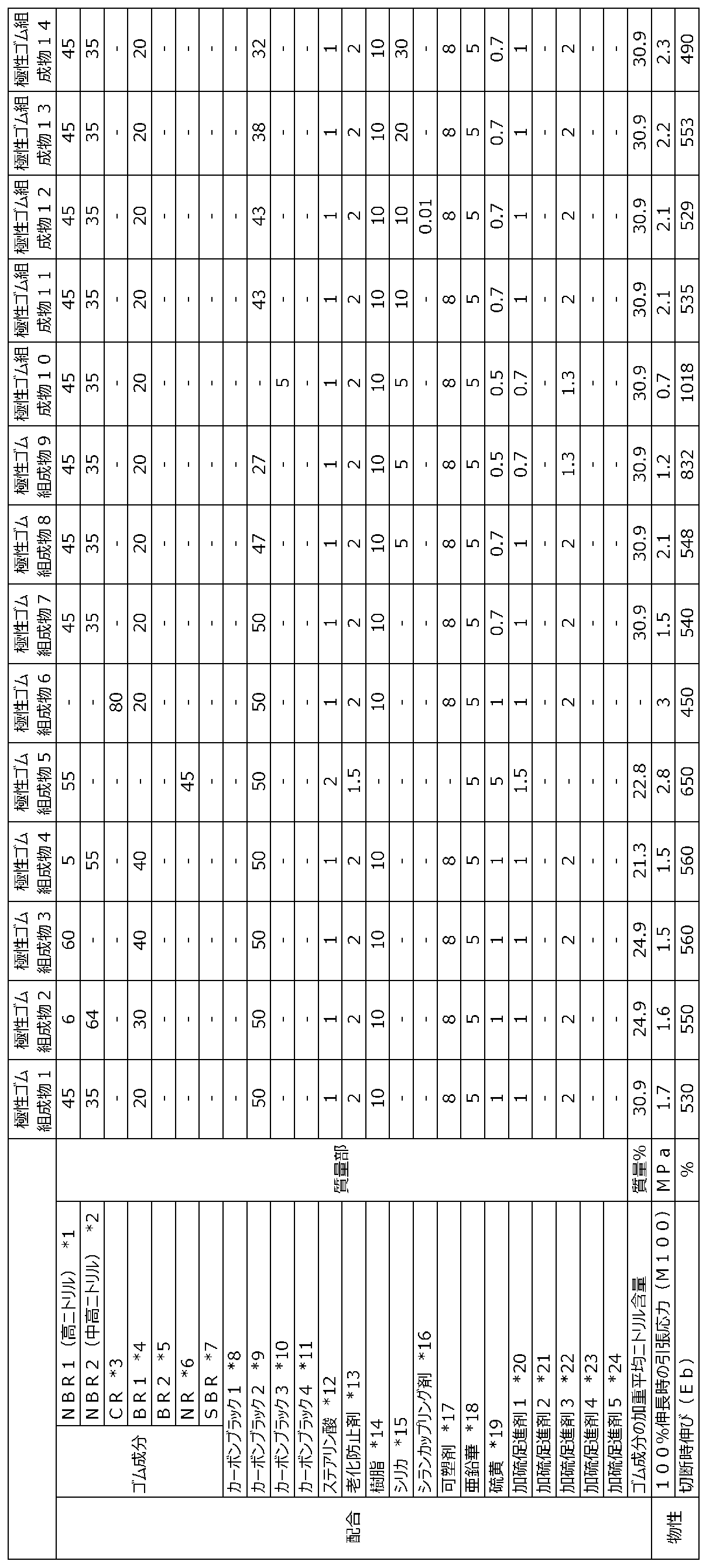
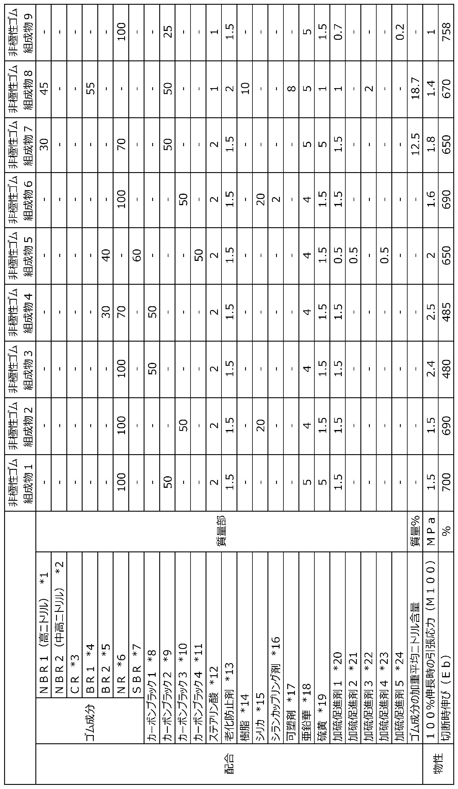
*1 NBR1(高ニトリル): アクリロニトリル-ブタジエンゴム、アクリロニトリル単位の含有量=41.5質量%、JSR株式会社製「N220S」、SP値=10.5(cal/cm3)1/2
*2 NBR2(中高ニトリル): アクリロニトリル-ブタジエンゴム、アクリロニトリル単位の含有量=35質量%、JSR株式会社製「N230S」、SP値=10.1(cal/cm3)1/2
*3 CR: クロロプレンゴム、東ソー株式会社製「スカイプレンB-30」、SP値=8.9(cal/cm3)1/2
*4 BR1: ビニルシス-ブタジエンゴム(VC-BR)、宇部興産株式会社製「UBEPOL(登録商標)BR150」、シス-1,4結合含有量98質量%、SP値=8.3(cal/cm3)1/2
*5 BR2: ブタジエンゴム、JSR株式会社製「BR01」、SP値=8.3(cal/cm3)1/2
*6 NR: 天然ゴム、RSS#3、SP値=8.2(cal/cm3)1/2
*7 SBR: スチレン-ブタジエンゴム、JSR株式会社製「#1500」、SP値=8.4(cal/cm3)1/2
*8 カーボンブラック1: SAF級カーボンブラック、N134、東海カーボン株式会社製「シースト9H」、窒素吸着比表面積=145m2/g
*9 カーボンブラック2: HAF級カーボンブラック、N330、東海カーボン株式会社製「シースト3」、窒素吸着比表面積=79m2/g
*10 カーボンブラック3: HAF級カーボンブラック、N326、旭カーボン株式会社製「旭#70L」、窒素吸着比表面積=84m2/g
*11 カーボンブラック4: ISAF級カーボンブラック、N234、東海カーボン株式会社製「シースト7HM」、窒素吸着比表面積=126m2/g
*12 ステアリン酸: 新日本理化株式会社製「ステアリン酸50S」
*13 老化防止剤: 大内新興化学工業株式会社製「ノクラック6C」
*14 樹脂: 日本ゼオン株式会社製「クレイトン100」
*15 シリカ: 東ソー・シリカ株式会社製「Nipsil AQ」
*16 シランカップリグ剤: Evonic社製「Si69」
*17 可塑剤: 新日本理化株式会社製「サンソサイザーDOA」
*18 亜鉛華: ZnO、白水化学工業株式会社製「亜鉛華3号」
*19 硫黄: 鶴見化学工業株式会社製「Sulfax Z」
*20 加硫促進剤1: 加硫促進剤CBS、大内新興化学工業株式会社製「ノクセラーCZ」
*21 加硫促進剤2: 加硫促進剤DPG、大内新興化学工業株式会社製「ノクセラーD」
*22 加硫促進剤3: 加硫促進剤TOT、大内新興化学工業株式会社製「ノクセラーTOT-N」
*23 加硫促進剤4: 加硫促進剤MTBS、大内新興化学工業株式会社製「ノクセラーDM」
*24 加硫促進剤5: 加硫促進剤DPG、住友化学株式会社製「ソクシノールD-Z」
*2 NBR2(中高ニトリル): アクリロニトリル-ブタジエンゴム、アクリロニトリル単位の含有量=35質量%、JSR株式会社製「N230S」、SP値=10.1(cal/cm3)1/2
*3 CR: クロロプレンゴム、東ソー株式会社製「スカイプレンB-30」、SP値=8.9(cal/cm3)1/2
*4 BR1: ビニルシス-ブタジエンゴム(VC-BR)、宇部興産株式会社製「UBEPOL(登録商標)BR150」、シス-1,4結合含有量98質量%、SP値=8.3(cal/cm3)1/2
*5 BR2: ブタジエンゴム、JSR株式会社製「BR01」、SP値=8.3(cal/cm3)1/2
*6 NR: 天然ゴム、RSS#3、SP値=8.2(cal/cm3)1/2
*7 SBR: スチレン-ブタジエンゴム、JSR株式会社製「#1500」、SP値=8.4(cal/cm3)1/2
*8 カーボンブラック1: SAF級カーボンブラック、N134、東海カーボン株式会社製「シースト9H」、窒素吸着比表面積=145m2/g
*9 カーボンブラック2: HAF級カーボンブラック、N330、東海カーボン株式会社製「シースト3」、窒素吸着比表面積=79m2/g
*10 カーボンブラック3: HAF級カーボンブラック、N326、旭カーボン株式会社製「旭#70L」、窒素吸着比表面積=84m2/g
*11 カーボンブラック4: ISAF級カーボンブラック、N234、東海カーボン株式会社製「シースト7HM」、窒素吸着比表面積=126m2/g
*12 ステアリン酸: 新日本理化株式会社製「ステアリン酸50S」
*13 老化防止剤: 大内新興化学工業株式会社製「ノクラック6C」
*14 樹脂: 日本ゼオン株式会社製「クレイトン100」
*15 シリカ: 東ソー・シリカ株式会社製「Nipsil AQ」
*16 シランカップリグ剤: Evonic社製「Si69」
*17 可塑剤: 新日本理化株式会社製「サンソサイザーDOA」
*18 亜鉛華: ZnO、白水化学工業株式会社製「亜鉛華3号」
*19 硫黄: 鶴見化学工業株式会社製「Sulfax Z」
*20 加硫促進剤1: 加硫促進剤CBS、大内新興化学工業株式会社製「ノクセラーCZ」
*21 加硫促進剤2: 加硫促進剤DPG、大内新興化学工業株式会社製「ノクセラーD」
*22 加硫促進剤3: 加硫促進剤TOT、大内新興化学工業株式会社製「ノクセラーTOT-N」
*23 加硫促進剤4: 加硫促進剤MTBS、大内新興化学工業株式会社製「ノクセラーDM」
*24 加硫促進剤5: 加硫促進剤DPG、住友化学株式会社製「ソクシノールD-Z」
(チューブの作製)
得られたゴム組成物を押出し成形機で加工することにより、長さ300mmの円筒形状のチューブを作製した。なお、実施例1~27及び比較例6~7については、図3に示すような内層と外層の2層構造のチューブを作製し、比較例1~5については、単層構造のチューブを作製した。各層に使用したゴム組成物の配合、並びに、チューブの内径及び外径、チューブの厚みに占める内層及び外層の割合を表3~表4に示す。
得られたゴム組成物を押出し成形機で加工することにより、長さ300mmの円筒形状のチューブを作製した。なお、実施例1~27及び比較例6~7については、図3に示すような内層と外層の2層構造のチューブを作製し、比較例1~5については、単層構造のチューブを作製した。各層に使用したゴム組成物の配合、並びに、チューブの内径及び外径、チューブの厚みに占める内層及び外層の割合を表3~表4に示す。
(スリーブの作製)
原糸として、2200dtexのアラミド繊維を2本を用い、12回/10cmの下撚りをけ、更に12回/10cmの上撚りをかけて、直径0.7mmのアラミド繊維コードを作製した。該アラミド繊維コード64本を編み込んで作製した網目状のスリーブを用意した。このスリーブは、横断面において円周上にアラミド繊維コードが64本観察される網目状筒状体であった。具体的には、このスリーブは、等間隔、平行かつ螺旋状に配置された32本のアラミド繊維コードと、この32本のアラミド繊維コードと斜交するとともに、等間隔、平行かつ螺旋状に配置された他の32本のアラミド繊維コードとが交互に編み込まれてなる網目状筒状体であり、各コードのスリーブの軸方向に対する角度は25度であった。
原糸として、2200dtexのアラミド繊維を2本を用い、12回/10cmの下撚りをけ、更に12回/10cmの上撚りをかけて、直径0.7mmのアラミド繊維コードを作製した。該アラミド繊維コード64本を編み込んで作製した網目状のスリーブを用意した。このスリーブは、横断面において円周上にアラミド繊維コードが64本観察される網目状筒状体であった。具体的には、このスリーブは、等間隔、平行かつ螺旋状に配置された32本のアラミド繊維コードと、この32本のアラミド繊維コードと斜交するとともに、等間隔、平行かつ螺旋状に配置された他の32本のアラミド繊維コードとが交互に編み込まれてなる網目状筒状体であり、各コードのスリーブの軸方向に対する角度は25度であった。
(アクチュエータの作製)
前記チューブと前記網目状のスリーブとを用いて、図1及び図2に示す構造のアクチュエータを作製した。なお、封止機構200と封止機構300との間の長さは250mmである。アクチュエータに組み込まれたチューブの作動油としては、コスモスーパーエポック株式会社製UF46を用いた。作製したアクチュエータの耐久性を、以下の方法で評価した。結果を表3~表4に示す。
前記チューブと前記網目状のスリーブとを用いて、図1及び図2に示す構造のアクチュエータを作製した。なお、封止機構200と封止機構300との間の長さは250mmである。アクチュエータに組み込まれたチューブの作動油としては、コスモスーパーエポック株式会社製UF46を用いた。作製したアクチュエータの耐久性を、以下の方法で評価した。結果を表3~表4に示す。
<アクチュエータの耐久性の評価方法>
作動油をチューブ内に注入して、チューブ内の空気を作動油で十分に置換した。チューブ内の作動油の圧力が0MPaと5MPaとをそれぞれ3秒ごとに繰り返すように作動油の注入操作を行い、チューブに亀裂が入り、該亀裂が進展して、アクチュエータの機能を発現できなくなるまでの回数を測定した。表3においては、比較例1の回数を100として、指数表示し、表4においては、実施例25の回数を100として、指数表示した。指数値が大きい程、耐久性(耐亀裂進展性)が高いことを示す。
作動油をチューブ内に注入して、チューブ内の空気を作動油で十分に置換した。チューブ内の作動油の圧力が0MPaと5MPaとをそれぞれ3秒ごとに繰り返すように作動油の注入操作を行い、チューブに亀裂が入り、該亀裂が進展して、アクチュエータの機能を発現できなくなるまでの回数を測定した。表3においては、比較例1の回数を100として、指数表示し、表4においては、実施例25の回数を100として、指数表示した。指数値が大きい程、耐久性(耐亀裂進展性)が高いことを示す。
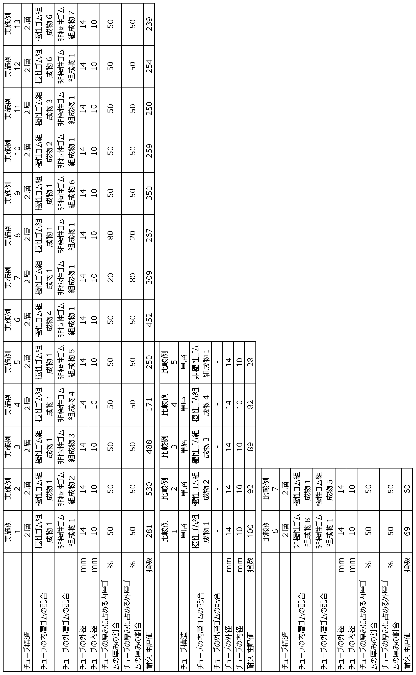

表3から、本発明に従う液圧式アクチュエータは、高い耐久性を有することが分かる。
また、表4から、極性ゴム層がシリカを含み、該シリカの含有量が、極性ゴム層中のゴム成分100質量部に対して5~20質量部の場合、液圧式アクチュエータの耐久性が更に向上することが分かる。
また、表4から、極性ゴム層がシリカを含み、該シリカの含有量が、極性ゴム層中のゴム成分100質量部に対して5~20質量部の場合、液圧式アクチュエータの耐久性が更に向上することが分かる。
10:液圧式アクチュエータ、 20:連結部、 100:アクチュエータ本体部、 110:チューブ、 111:極性ゴム層、 112:非極性ゴム層、 120:スリーブ、 120a:第1折り返し部、 120b:スリーブ本体部、 120c:第2折り返し部、 200,200A,200B,200C:封止機構、 210,210A,210B,210C:封止部材、 211,211A,211B,211C:胴体部、 212,212A:鍔部、 213:凹凸部、 214,214B:第1小径部、 215:通過孔、 216B:第2小径部、 220,220A,220B,220C:第1係止リング、 230,230A,230B,230C:かしめ部材、 231:圧痕、 240:接着層、 250,250A:ゴムシート、 260:ゴムシート、 270,270C:第2係止リング、 280,281:ゴムシート、 290,291:ゴムシート、 300:封止機構、 400:フィッティング、 410:通過孔、 DAX:軸方向、 DR:径方向
Claims (17)
- 液圧によって膨張及び収縮する筒状のチューブと、所定方向に配向されたコードを編み込んだ筒状の構造体であって前記チューブの外周面を覆うスリーブと、によって構成されるアクチュエータ本体部を具え、
前記チューブは、SP値が8.7以上である極性ゴムの含有率がゴム成分中50質量%以上である極性ゴム層及びSP値が8.7以上である極性ゴムの含有率がゴム成分中50質量%未満である非極性ゴム層からなる2層以上の積層構造を有することを特徴とする、液圧式アクチュエータ。 - 前記極性ゴム層が、前記チューブの最内側に配置されている、請求項1に記載の液圧式アクチュエータ。
- 前記非極性ゴム層が、前記極性ゴム層の径方向外側であって、前記チューブの最外側に配置されている、請求項1又は2に記載の液圧式アクチュエータ。
- 前記極性ゴム層が、アクリロニトリル-ブタジエンゴムおよび/または水素化アクリロニトリルブタジエンゴムを含む、請求項1~3のいずれか一項に記載の液圧式アクチュエータ。
- 前記アクリロニトリル-ブタジエンゴムおよび/または水素化アクリロニトリルブタジエンゴムは、アクリロニトリル単位の含有量が20質量%~50質量%である、請求項4に記載の液圧式アクチュエータ。
- 前記アクリロニトリル-ブタジエンゴムおよび/または水素化アクリロニトリルブタジエンゴムは、アクリロニトリル単位の含有量が異なる2種類以上のアクリロニトリル-ブタジエンゴムおよび/または水素化アクリロニトリルブタジエンゴムを含む、請求項4又は5に記載の液圧式アクチュエータ。
- 前記極性ゴム層は、更にSP値が8.7未満である非極性ジエン系ゴムを含む、請求項1~6のいずれか一項に記載の液圧式アクチュエータ。
- 前記極性ゴム層は、前記ゴム成分の加重平均ニトリル含量が20質量%以上45質量%以下である、請求項1~7のいずれか一項に記載の液圧式アクチュエータ。
- 前記非極性ゴム層が、ブタジエンゴム、天然ゴム、合成イソプレンゴム、スチレン-ブタジエンゴム、ブチルゴムからなる群から選択される1種類以上を含む、請求項1~8のいずれか一項に記載の液圧式アクチュエータ。
- 前記極性ゴム層及び前記非極性ゴム層が、カーボンブラックを含む、請求項1~9のいずれか一項に記載の液圧式アクチュエータ。
- 前記非極性ゴム層に含まれるカーボンブラックは、窒素吸着比表面積が34m2/g~155m2/gである、請求項10に記載の液圧式アクチュエータ。
- 前記非極性ゴム層が、更にシリカを含む、請求項1~11のいずれか一項に記載の液圧式アクチュエータ。
- 前記非極性ゴム層が、更にシランカップリング剤を含む、請求項12に記載の液圧式アクチュエータ。
- 前記極性ゴム層が、更にシリカを含み、該シリカの含有量が、当該極性ゴム層中のゴム成分100質量部に対して5~20質量部である、請求項1~13のいずれか一項に記載の液圧式アクチュエータ。
- 前記極性ゴム層が、更に、前記シリカ100質量部に対して、シランカップリング剤を0.1質量部以下含む、請求項14に記載の液圧式アクチュエータ。
- 前記極性ゴム層の総厚みが、前記チューブの総厚みの10%~90%であり、
前記非極性ゴム層の総厚みが、前記チューブの総厚みの90%~10%である、請求項1~15のいずれか一項に記載の液圧式アクチュエータ。 - 前記非極性ゴム層は、100%伸長時の引張応力(M100)が1.0MPa以上である、請求項1~16のいずれか1項に記載の液圧式アクチュエータ。
Priority Applications (4)
| Application Number | Priority Date | Filing Date | Title |
|---|---|---|---|
| JP2018549001A JPWO2018084123A1 (ja) | 2016-11-07 | 2017-10-30 | 液圧式アクチュエータ |
| US16/347,719 US20190316608A1 (en) | 2016-11-07 | 2017-10-30 | Hydraulic actuator |
| EP17867303.4A EP3536981A4 (en) | 2016-11-07 | 2017-10-30 | HYDRAULIC ACTUATOR |
| CN201780068415.4A CN109937307A (zh) | 2016-11-07 | 2017-10-30 | 液压致动器 |
Applications Claiming Priority (4)
| Application Number | Priority Date | Filing Date | Title |
|---|---|---|---|
| JP2016-217533 | 2016-11-07 | ||
| JP2016217533 | 2016-11-07 | ||
| JP2017-099998 | 2017-05-19 | ||
| JP2017099998 | 2017-05-19 |
Publications (1)
| Publication Number | Publication Date |
|---|---|
| WO2018084123A1 true WO2018084123A1 (ja) | 2018-05-11 |
Family
ID=62075783
Family Applications (1)
| Application Number | Title | Priority Date | Filing Date |
|---|---|---|---|
| PCT/JP2017/039199 Ceased WO2018084123A1 (ja) | 2016-11-07 | 2017-10-30 | 液圧式アクチュエータ |
Country Status (5)
| Country | Link |
|---|---|
| US (1) | US20190316608A1 (ja) |
| EP (1) | EP3536981A4 (ja) |
| JP (1) | JPWO2018084123A1 (ja) |
| CN (1) | CN109937307A (ja) |
| WO (1) | WO2018084123A1 (ja) |
Cited By (4)
| Publication number | Priority date | Publication date | Assignee | Title |
|---|---|---|---|---|
| WO2020080545A1 (ja) | 2018-10-19 | 2020-04-23 | 株式会社ブリヂストン | アクチュエータ |
| JP2020066640A (ja) * | 2018-10-19 | 2020-04-30 | 株式会社ブリヂストン | アクチュエータ用ゴム組成物、アクチュエータ用加硫ゴム及びアクチュエータ |
| JP2020066641A (ja) * | 2018-10-19 | 2020-04-30 | 株式会社ブリヂストン | アクチュエータ用ゴム組成物、アクチュエータ用加硫ゴム及びアクチュエータ |
| WO2024176566A1 (ja) * | 2023-02-22 | 2024-08-29 | 株式会社ブリヂストン | ホース用ゴム組成物及びホース |
Families Citing this family (1)
| Publication number | Priority date | Publication date | Assignee | Title |
|---|---|---|---|---|
| JP7833269B2 (ja) * | 2021-08-25 | 2026-03-19 | 株式会社ブリヂストン | センシング用導電性ゴム組成物 |
Citations (4)
| Publication number | Priority date | Publication date | Assignee | Title |
|---|---|---|---|---|
| JPS61236905A (ja) | 1985-04-12 | 1986-10-22 | Bridgestone Corp | ニユ−マチツク・アクチユエ−タ |
| US4721030A (en) * | 1985-07-16 | 1988-01-26 | Paynter Henry M | Hyperboloid of revolution fluid-driven tension actuators and method of making |
| JPH04337185A (ja) * | 1991-05-14 | 1992-11-25 | Toyoda Gosei Co Ltd | 複層ゴムホース |
| JP2017046754A (ja) * | 2015-08-31 | 2017-03-09 | ダイヤ工業株式会社 | アクチュエータ及び身体支援装置 |
Family Cites Families (13)
| Publication number | Priority date | Publication date | Assignee | Title |
|---|---|---|---|---|
| FR2700810A3 (fr) * | 1993-01-26 | 1994-07-29 | Le Masson Yves | Organe de tension à tension variable commandée pneumatiquement et ses applications. |
| JPH08170603A (ja) * | 1994-12-16 | 1996-07-02 | Hitachi Cable Ltd | アクチュエータ |
| JP4350824B2 (ja) * | 1998-12-25 | 2009-10-21 | 住友ゴム工業株式会社 | ゴム手袋およびその製造方法 |
| US6689074B2 (en) * | 2000-03-28 | 2004-02-10 | Seiko Epson Corporation | Wearable muscular-force supplementing device |
| JP2001355608A (ja) * | 2000-06-14 | 2001-12-26 | Toray Eng Co Ltd | アクチュエータ |
| US20020108491A1 (en) * | 2001-02-13 | 2002-08-15 | Stahn Kevin S. | Tension actuator having constraining sleeve immersed in a single layer of elastomeric material |
| US6666127B2 (en) * | 2002-05-03 | 2003-12-23 | Muscle Tech Ltd. | Artificial muscle |
| ES2309204T3 (es) * | 2002-09-25 | 2008-12-16 | Hutchinson | Tubo, en particular para un circuito de admision de aire en un motor de un vehiculo automovil. |
| JP3984641B2 (ja) * | 2004-09-01 | 2007-10-03 | 松下電器産業株式会社 | 関節駆動装置 |
| JP5246717B2 (ja) * | 2007-05-11 | 2013-07-24 | 学校法人 中央大学 | 流体注入型アクチュエータ |
| JP6226359B2 (ja) * | 2013-05-16 | 2017-11-08 | 国立大学法人 岡山大学 | 流体圧式アクチュエータおよび湾曲駆動装置 |
| WO2016011345A1 (en) * | 2014-07-17 | 2016-01-21 | President And Fellows Of Harvard College | Soft actuators and soft actuating devices |
| CN105805076B (zh) * | 2016-04-26 | 2017-11-14 | 中国计量大学 | 气动肌肉及其实现的驱动机构 |
-
2017
- 2017-10-30 EP EP17867303.4A patent/EP3536981A4/en not_active Withdrawn
- 2017-10-30 US US16/347,719 patent/US20190316608A1/en not_active Abandoned
- 2017-10-30 CN CN201780068415.4A patent/CN109937307A/zh active Pending
- 2017-10-30 JP JP2018549001A patent/JPWO2018084123A1/ja active Pending
- 2017-10-30 WO PCT/JP2017/039199 patent/WO2018084123A1/ja not_active Ceased
Patent Citations (4)
| Publication number | Priority date | Publication date | Assignee | Title |
|---|---|---|---|---|
| JPS61236905A (ja) | 1985-04-12 | 1986-10-22 | Bridgestone Corp | ニユ−マチツク・アクチユエ−タ |
| US4721030A (en) * | 1985-07-16 | 1988-01-26 | Paynter Henry M | Hyperboloid of revolution fluid-driven tension actuators and method of making |
| JPH04337185A (ja) * | 1991-05-14 | 1992-11-25 | Toyoda Gosei Co Ltd | 複層ゴムホース |
| JP2017046754A (ja) * | 2015-08-31 | 2017-03-09 | ダイヤ工業株式会社 | アクチュエータ及び身体支援装置 |
Non-Patent Citations (1)
| Title |
|---|
| See also references of EP3536981A4 * |
Cited By (7)
| Publication number | Priority date | Publication date | Assignee | Title |
|---|---|---|---|---|
| WO2020080545A1 (ja) | 2018-10-19 | 2020-04-23 | 株式会社ブリヂストン | アクチュエータ |
| JP2020066640A (ja) * | 2018-10-19 | 2020-04-30 | 株式会社ブリヂストン | アクチュエータ用ゴム組成物、アクチュエータ用加硫ゴム及びアクチュエータ |
| JP2020066641A (ja) * | 2018-10-19 | 2020-04-30 | 株式会社ブリヂストン | アクチュエータ用ゴム組成物、アクチュエータ用加硫ゴム及びアクチュエータ |
| JP7171993B2 (ja) | 2018-10-19 | 2022-11-16 | 株式会社ブリヂストン | アクチュエータ用ゴム組成物、アクチュエータ用加硫ゴム及びアクチュエータ |
| JP7171994B2 (ja) | 2018-10-19 | 2022-11-16 | 株式会社ブリヂストン | アクチュエータ用ゴム組成物、アクチュエータ用加硫ゴム及びアクチュエータ |
| US11821114B2 (en) | 2018-10-19 | 2023-11-21 | Bridgestone Corporation | Actuator |
| WO2024176566A1 (ja) * | 2023-02-22 | 2024-08-29 | 株式会社ブリヂストン | ホース用ゴム組成物及びホース |
Also Published As
| Publication number | Publication date |
|---|---|
| CN109937307A (zh) | 2019-06-25 |
| US20190316608A1 (en) | 2019-10-17 |
| EP3536981A1 (en) | 2019-09-11 |
| EP3536981A4 (en) | 2020-07-08 |
| JPWO2018084123A1 (ja) | 2019-09-19 |
Similar Documents
| Publication | Publication Date | Title |
|---|---|---|
| JPWO2018084123A1 (ja) | 液圧式アクチュエータ | |
| CN101627083B (zh) | 橡胶组合物和使用该橡胶组合物的硫化橡胶制品 | |
| US20150183970A1 (en) | Rubber Composition, and Vulcanized Rubber Product and Hose Using Same | |
| US20130040771A1 (en) | Power transmission belt, in particular toothed belt | |
| JP2022029842A (ja) | センシング用導電性ゴム組成物 | |
| JP6865635B2 (ja) | 液圧式アクチュエータ | |
| JP7323551B2 (ja) | アクチュエータ | |
| JP6908466B2 (ja) | 液圧式アクチュエータ | |
| JP6663798B2 (ja) | 油圧式アクチュエータ | |
| WO2023026620A1 (ja) | センシング用導電性ゴム組成物 | |
| JP5044912B2 (ja) | ゴム組成物 | |
| WO2018084122A1 (ja) | 液圧式アクチュエータ | |
| JP7171994B2 (ja) | アクチュエータ用ゴム組成物、アクチュエータ用加硫ゴム及びアクチュエータ | |
| JP7171993B2 (ja) | アクチュエータ用ゴム組成物、アクチュエータ用加硫ゴム及びアクチュエータ | |
| JP7833269B2 (ja) | センシング用導電性ゴム組成物 | |
| WO2023008066A1 (ja) | ホース内管用ゴム組成物、積層体及びホース | |
| JP2008132641A (ja) | 筒状可撓膜体 | |
| JP7650752B2 (ja) | センシング用導電性ゴム組成物 | |
| JP7804432B2 (ja) | センシング用導電性ゴム組成物 | |
| JP2021076167A (ja) | 流体圧式アクチュエータ及び人工筋肉 | |
| WO2022113671A1 (ja) | ホース内管用ゴム組成物、積層体及びホース | |
| JP2023031810A (ja) | センシング用導電性ゴム組成物 | |
| JP2022085771A (ja) | ホース内管用ゴム組成物、積層体及びホース | |
| JP2023031813A (ja) | センシング用導電性ゴム組成物 | |
| JP2023031816A (ja) | センシング用導電性ゴム組成物 |
Legal Events
| Date | Code | Title | Description |
|---|---|---|---|
| 121 | Ep: the epo has been informed by wipo that ep was designated in this application |
Ref document number: 17867303 Country of ref document: EP Kind code of ref document: A1 |
|
| ENP | Entry into the national phase |
Ref document number: 2018549001 Country of ref document: JP Kind code of ref document: A |
|
| NENP | Non-entry into the national phase |
Ref country code: DE |
|
| ENP | Entry into the national phase |
Ref document number: 2017867303 Country of ref document: EP Effective date: 20190607 |