WO2018084227A1 - Dispositif terminal, procédé d'exploitation et programme - Google Patents
Dispositif terminal, procédé d'exploitation et programme Download PDFInfo
- Publication number
- WO2018084227A1 WO2018084227A1 PCT/JP2017/039664 JP2017039664W WO2018084227A1 WO 2018084227 A1 WO2018084227 A1 WO 2018084227A1 JP 2017039664 W JP2017039664 W JP 2017039664W WO 2018084227 A1 WO2018084227 A1 WO 2018084227A1
- Authority
- WO
- WIPO (PCT)
- Prior art keywords
- detection unit
- visual information
- event
- terminal device
- unit
- Prior art date
- Legal status (The legal status is an assumption and is not a legal conclusion. Google has not performed a legal analysis and makes no representation as to the accuracy of the status listed.)
- Ceased
Links
Images







Classifications
-
- G—PHYSICS
- G02—OPTICS
- G02B—OPTICAL ELEMENTS, SYSTEMS OR APPARATUS
- G02B27/00—Optical systems or apparatus not provided for by any of the groups G02B1/00 - G02B26/00, G02B30/00
- G02B27/01—Head-up displays
- G02B27/017—Head mounted
-
- G—PHYSICS
- G06—COMPUTING OR CALCULATING; COUNTING
- G06V—IMAGE OR VIDEO RECOGNITION OR UNDERSTANDING
- G06V20/00—Scenes; Scene-specific elements
- G06V20/40—Scenes; Scene-specific elements in video content
- G06V20/41—Higher-level, semantic clustering, classification or understanding of video scenes, e.g. detection, labelling or Markovian modelling of sport events or news items
-
- G—PHYSICS
- G09—EDUCATION; CRYPTOGRAPHY; DISPLAY; ADVERTISING; SEALS
- G09G—ARRANGEMENTS OR CIRCUITS FOR CONTROL OF INDICATING DEVICES USING STATIC MEANS TO PRESENT VARIABLE INFORMATION
- G09G5/00—Control arrangements or circuits for visual indicators common to cathode-ray tube indicators and other visual indicators
-
- G—PHYSICS
- G09—EDUCATION; CRYPTOGRAPHY; DISPLAY; ADVERTISING; SEALS
- G09G—ARRANGEMENTS OR CIRCUITS FOR CONTROL OF INDICATING DEVICES USING STATIC MEANS TO PRESENT VARIABLE INFORMATION
- G09G5/00—Control arrangements or circuits for visual indicators common to cathode-ray tube indicators and other visual indicators
- G09G5/10—Intensity circuits
-
- H—ELECTRICITY
- H04—ELECTRIC COMMUNICATION TECHNIQUE
- H04N—PICTORIAL COMMUNICATION, e.g. TELEVISION
- H04N5/00—Details of television systems
- H04N5/64—Constructional details of receivers, e.g. cabinets or dust covers
-
- G—PHYSICS
- G02—OPTICS
- G02B—OPTICAL ELEMENTS, SYSTEMS OR APPARATUS
- G02B27/00—Optical systems or apparatus not provided for by any of the groups G02B1/00 - G02B26/00, G02B30/00
- G02B27/01—Head-up displays
- G02B27/0101—Head-up displays characterised by optical features
- G02B2027/0138—Head-up displays characterised by optical features comprising image capture systems, e.g. camera
-
- G—PHYSICS
- G02—OPTICS
- G02B—OPTICAL ELEMENTS, SYSTEMS OR APPARATUS
- G02B27/00—Optical systems or apparatus not provided for by any of the groups G02B1/00 - G02B26/00, G02B30/00
- G02B27/01—Head-up displays
- G02B27/0101—Head-up displays characterised by optical features
- G02B2027/014—Head-up displays characterised by optical features comprising information/image processing systems
-
- G—PHYSICS
- G02—OPTICS
- G02B—OPTICAL ELEMENTS, SYSTEMS OR APPARATUS
- G02B27/00—Optical systems or apparatus not provided for by any of the groups G02B1/00 - G02B26/00, G02B30/00
- G02B27/01—Head-up displays
- G02B27/017—Head mounted
- G02B2027/0178—Eyeglass type
-
- G—PHYSICS
- G06—COMPUTING OR CALCULATING; COUNTING
- G06V—IMAGE OR VIDEO RECOGNITION OR UNDERSTANDING
- G06V20/00—Scenes; Scene-specific elements
- G06V20/40—Scenes; Scene-specific elements in video content
- G06V20/44—Event detection
-
- G—PHYSICS
- G06—COMPUTING OR CALCULATING; COUNTING
- G06V—IMAGE OR VIDEO RECOGNITION OR UNDERSTANDING
- G06V2201/00—Indexing scheme relating to image or video recognition or understanding
- G06V2201/08—Detecting or categorising vehicles
Definitions
- the present invention relates to a terminal device, an operation method, and a program.
- Such an information terminal device is called a wearable terminal.
- One type of wearable terminal is a glasses-type terminal.
- the glasses-type terminal includes a glasses-type display and a wearing tool that can be worn on the head. With such a configuration, physical burden and psychological resistance associated with wearing are reduced.
- the glasses-type terminal can present visual information such as images and characters to individual users. There are some which can provide various functions through presentation of this visual information.
- Patent Document 1 is attached to the user's head and torso, detects the rotational movements of the head and torso, obtains the swing angle of the user based on the detection result, and displays an image in the user's field of view. And an image display system that starts image display based on the line-of-sight direction and the swing angle.
- One aspect of the present invention has been made in view of the above points, and provides a terminal device, an operation method, and a program capable of improving safety for a user wearing the device.
- One embodiment of the present invention has been made to solve the above-described problem, and one embodiment of the present invention includes a display unit capable of displaying visually-visible visual information on an outside scene, and visual recognition of the visual information.
- a detection unit capable of detecting an event that may cause danger
- a mounting unit that can be mounted on a user's head and supports the display unit and the detection unit, and when the event is detected, to the display unit
- a control unit that suppresses display of visual information.
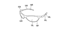
- FIG. 1 is a perspective view illustrating an example of an external configuration of a terminal device 10 according to the present embodiment.
- the terminal device 10 is a glasses-type terminal that can be worn on the user's head.
- the terminal device 10 includes a main body 10A, two display units 13L and 13R, two playback units 14L and 14R, two arms 19L and 19R, and one frame 19F.
- the main body 10A performs processing for executing various functions of the terminal device 10. A functional configuration example of the main body 10A will be described later.
- Display units 13L and 13R each have a display device disposed on the surface of a member that transmits visible light.
- the member that transmits visible light is, for example, glass or polyethylene.
- Each display device displays visual information indicated by an image signal input from the main body 10A.
- the display device is, for example, an organic EL (Electro Luminescence) display.
- the outer edges of the display parts 13L and 13R are supported by the inner edges of the two ring parts of the frame 19F.
- the display units 13L and 13R present visual information to the left eye and the right eye of the user wearing the terminal device 10, respectively. Therefore, the display units 13L and 13R function as a transmissive display that superimposes visual information on an outside scene represented by incident light from the outside world.
- the display device is not necessarily limited to an organic EL display, and may be a liquid crystal display, for example. Further, the visual information presentation method by the display device is not necessarily limited to the transmission type, and may be, for example, a retinal projection method.
- Each of the reproduction units 14L and 14R includes a receiver that generates sound. Each receiver presents auditory information by reproducing sound indicated by an acoustic signal input from the main unit 10A.
- the reproduction units 14L and 14R are mounted at positions closer to the other end than one end of the arms 19L and 19R, respectively.
- the reproduction units 14L and 14R are located in the vicinity of the left ear and the right ear of the user wearing the terminal device 10, respectively, and present auditory information at the positions.
- auditory information presented to the left and right ears may be referred to as left auditory information and right auditory information, respectively.
- the frame 19F has two ring portions, and the outer edges of the ring portions are bonded to each other. Both ends of the frame 19F are hinged to one ends of the arms 19L and 19R, respectively. The other ends of the arms 19L and 19R are curved in the same direction. With this shape, the other ends of the arms 19L and 19R are sandwiched between the user's pinna and the head, and the center of the frame 19F is supported at the user's nasal root. Since the frame 19F and the arms 19L and 19R have such a configuration, the terminal device 10 can be mounted on the user's head as a series of mounting portions.
- FIG. 2 is a block diagram illustrating an example of a functional configuration of the terminal device 10 according to the present embodiment.
- the terminal apparatus 10 includes a control unit 11, a command input unit 15, an observation signal detection unit 16, a storage unit 17, and a communication unit 18 in the main body unit 10A.
- the control unit 11 controls the operation of the terminal device 10.
- the control unit 11 includes a function control unit 111, an event detection unit 112, a visual information control unit 113, and an auditory information control unit 114.
- the function control unit 111 determines a command indicated by the command input signal input from the command input unit 15.
- the command is a command for controlling the function of the terminal device 10, for example, start or end of a function to be controlled, change of an operation mode, or the like.
- the functions of the terminal device 10 include, for example, guidance using various exercises and work training, reproduction of content such as video and music, communication with a counterpart device, and the like.
- the function control unit 111 starts processing instructed by an instruction described in the application program corresponding to the command.
- the processing executed by the function control unit 111 includes processing for acquiring various visual information and auditory information.
- the visual information is information that can be visually recognized such as images, characters, symbols, and figures.
- the visual information includes, for example, information synthesized by the function control unit 111 such as augmented reality (AR) display, information read from the storage unit 17 such as guidance display, an image taken by a camera (not shown), a communication unit 18 May be any of the received information received from the counterpart device.
- Auditory information is information that can be recognized by hearing, such as voice, music, and sound effects.
- Auditory information includes, for example, information read from the storage unit 17 such as guidance voice, information synthesized by the function control unit 111, voice recorded by a microphone (not shown), voice received by the communication unit 18 from the other device, music , Received information such as sound effects, etc.
- the visual information includes left visual information to be displayed on the display unit 13L and right visual information to be displayed on the display unit 13R.
- One common visual information may be used as the left visual information and the right visual information, or different visual information such as a stereo image may be used.
- the auditory information includes left auditory information for reproduction by the reproduction unit 14L and right auditory information for reproduction by the reproduction unit 14R.
- One common auditory information may be used as the left auditory information and the right auditory information, or different auditory information such as stereo sound may be used.
- the function control unit 111 outputs the acquired visual information and auditory information to the visual information control unit 113 and the auditory information control unit 114, respectively.
- the event detection unit 112 detects an event (event) that may cause danger to the user by viewing the visual information displayed on the display units 13L and 13R based on the observation signal input from the observation signal detection unit 16.
- the configuration of the observation signal detection unit 16 and the type and mode of the observation signal may vary depending on the type of event to be detected.
- the possibility of creating a danger includes both the fact that a danger has actually occurred and the possibility that a danger is likely to occur. “Danger” means that safety is impaired, and injuries occur mainly in the user's body.
- a predetermined event includes an event in which the user's operation is irregular.
- the irregular motion typically means that the momentum in a predetermined rotational direction or spatial direction is larger than the predetermined momentum. More specifically, this is a sudden direction change of the head of the user wearing the terminal device 10. Such an event occurs when the user turns the direction of the head in those directions when the user listens to an operation sound from a vehicle or other object.
- the object is not limited to an inanimate object, and may be an organism or a person.
- the operation sound may be any of sound generated by the activity such as engine sound, sound generated by movement such as wind noise and friction sound, warning sound such as horn and buzzer, person's utterance, and animal sound.
- the event detection unit 112 uses, for example, an angular velocity signal and an acceleration signal input as observation signals.
- the event detection unit 112 specifies the direction of the gravitational acceleration component that is always detected from the acceleration in each direction in the three-dimensional space indicated by the acceleration signal as the vertical direction (z direction).
- the event detection unit 112 calculates an angular velocity component in a horizontal plane (xy plane) having the vertical direction as a rotation axis from the angular velocity signal.
- the event detection unit 112 determines that the head direction has suddenly changed when the absolute value of the angular velocity in the horizontal plane is larger than a predetermined angular velocity threshold.
- the event detection unit 112 generates an event detection signal indicating a sudden direction change of the head as a predetermined event, and outputs the generated event detection signal to the visual information control unit 113 and the auditory information control unit 114.
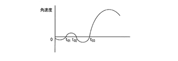
- the event detection unit 112 may detect a zero-cross point of the angular velocity in the horizontal plane.
- the zero cross point is a time point when the value changes from positive to negative or from negative to positive.
- times t 01 , t 02 , and t 03 are zero cross points.
- the event detection unit 112 time-integrates the angular velocity in the horizontal plane from the zero cross point detected immediately before, and calculates the angle from the direction at the zero cross point. In the example illustrated in FIG.
- the event detection unit 112 calculates the angle ⁇ at the current time t by time-integrating the angular velocity in the horizontal plane with reference to the direction ⁇ 03 of the head of the user Us at the time t 03 .
- the event detection unit 112 determines that the head direction has suddenly changed when the calculated angle is greater than a predetermined angle threshold. Therefore, it is possible to discriminate between a significant change in the direction of the head intended by the user and a minute change in the direction of the head that can always occur.
- Visual information is input to the visual information control unit 113 from the function control unit 111.
- the visual information control unit 113 suppresses output of the left visual information to the display unit 13L and output of the right visual information to the display unit 13R.
- the visual information can be suppressed by not outputting completely, or by reducing the luminance gain below the standard predetermined luminance gain. In the latter case, the visual information control unit 113 uses the left image signal and the right image indicating the luminance value for each pixel obtained by applying the reduced gain to the luminance values representing the left visual information and the right visual information. Each signal is generated.
- the visual information control unit 113 outputs the generated left image signal and right image signal to the display units 13L and 13R, respectively.
- the visual information control unit 113 applies a predetermined luminance gain to the luminance value representing the left visual information and the right visual information, and indicates the luminance value for each pixel.
- a left image signal and a right image signal are generated, respectively.
- the generated left image signal and right image signal are output to the display units 13L and 13R, respectively.
- Auditory information is input to the auditory information control unit 114 from the function control unit 111.
- the auditory information control unit 114 suppresses output of the left auditory information to the reproduction unit 14L and output of the right auditory information to the reproduction unit 14R.
- the auditory information control unit 114 applies a reduced gain to the left acoustic signal and the right acoustic signal indicating the amplitude value for each sample with respect to the amplitude values representing the left auditory information and the right auditory information.
- the auditory information control unit 114 outputs the generated left acoustic signal and right acoustic signal to the reproducing units 14L and 14R, respectively.
- the command input unit 15 receives a command instructed by the user and generates a command input signal indicating the received command.
- the command input unit 15 includes, for example, buttons that accept user operations, members such as knobs, touch sensors that indicate positions on the screen displayed on the display units 13L and 13R, and the like.
- the command input unit 15 may include a microphone (not shown) that records voice spoken by the user and a voice recognition unit (not shown) that performs voice recognition processing on the voice signal of the recorded voice. .
- the observation signal detector 16 detects an observation signal for use in detecting a predetermined event.
- the observation signal detection unit 16 includes a triaxial acceleration sensor and a triaxial angular velocity sensor.
- the sensitivity axes of the three acceleration sensors are the directions orthogonal to the rotation axes of the three angular velocity sensors.
- the storage unit 17 stores various data used by the control unit 11 for execution of processing and various data acquired by the control unit 11.
- the storage unit 17 includes a storage medium such as a RAM (Random Access Memory) and a ROM (Read-Only Memory).
- the communication unit 18 transmits and receives various types of data to and from the terminal device 10 via a network, or both.
- the network establishes a connection with a device (external device) separate from its own device in accordance with standards such as IEEE802.11 and LTE-A (Long Term Evolution-Advanced).
- the communication unit 18 includes a reception unit 181 and a transmission unit 182.
- the communication unit 18 includes, for example, a wireless communication interface.
- the receiving unit 181 receives a transmission wave carrying data transmitted from an external device as a received signal, demodulates the received signal, and outputs the carried data to the function control unit 111 as received data.
- the transmission unit 182 modulates transmission data input from the function control unit 111 and transmits a transmission signal obtained by the modulation to an external device.
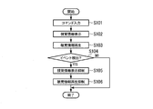
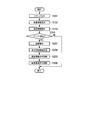
- FIG. 3 is a flowchart illustrating an example of the presentation information suppression process according to the present embodiment.
- the function control unit 111 determines the command indicated by the command input signal input from the command input unit 15.
- the function control unit 111 executes processing related to the function indicated by the determined command.
- the function control unit 111 outputs visual information and auditory information generated in the execution of the processing to the visual information control unit 113 and the auditory information control unit 114, respectively. Thereafter, the process proceeds to step S102.
- Step S102 The visual information control unit 113 causes the left visual information and right visual information input from the function control unit 111 to act on a predetermined luminance gain, and outputs them to the display units 13L and 13R, respectively.
- the display units 13L and 13R display left visual information and right visual information, respectively.
- the process proceeds to step S103.
- the auditory information control unit 114 applies a gain of a predetermined volume to the left auditory information and the right auditory information input from the function control unit 111, and outputs them to the reproducing units 14L and 14R, respectively.
- the reproduction units 14L and 14R reproduce the left auditory information and the right auditory information, respectively.
- step S104 The process proceeds to step S104.
- Step S ⁇ b> 104 The event detection unit 112 determines whether a predetermined event has been detected based on the observation signal input from the observation signal detection unit 16. When it is determined that it has been detected (YES in step S104), the process proceeds to step S105. When it is determined that no detection has been made (NO in step S104), the processing in FIG. 3 is terminated. (Step S105) When the event detection signal is input from the event detection unit 112, the visual information control unit 113 suppresses the output of the left visual information to the display unit 13L and the output of the right visual information to the display unit 13R, respectively. . Thereafter, the process proceeds to step S106.
- Step S106 When the event detection signal is input from the event detection unit 112, the auditory information control unit 114 suppresses the output of the left auditory information to the reproduction unit 14L and the output of the right auditory information to the reproduction unit 14R, respectively. . Thereafter, the process of FIG. 3 is terminated.
- FIG. 4 is a flowchart illustrating an example of the direction change detection process according to the present embodiment.
- Step S111 The event detection unit 112 detects an angular velocity in a horizontal plane from the angular velocity signal input from the observation signal detection unit 16. Thereafter, the process proceeds to step S112.
- Step S112 The event detection unit 112 detects the zero cross point from the detected angular velocity, calculates the angle in the horizontal plane from the direction at the zero cross point detected immediately before by integrating the angular velocity over time. Thereafter, the process proceeds to step S113.
- Step S113 The event detection unit 112 determines whether or not the calculated angle is larger than a predetermined angle. When it is determined that the value is larger (YES in step S113), the process proceeds to step S114. When it is determined that it is not large (NO in step S113), the process shown in FIG. 4 is terminated. (Step S114) The event detection unit 112 determines that a sudden direction change of the user's head has been detected as a predetermined event, and an event detection signal indicating the detected sudden direction change as detection of the predetermined event is a visual information control unit 113 and the auditory information control unit 114 respectively. Thereafter, the process shown in FIG.
- the event detection unit 112 detects a sudden change in the direction of the head as an event in which the user's movement is irregular is taken as an example, but the present invention is not limited thereto.
- the event detection unit 112 may detect a sudden change in the height of the head, that is, a vertical movement, instead of or in combination with the sudden change in the direction of the head.
- Such an event may occur when the stairs are raised or lowered and the posture is changed.
- the change in posture can occur, for example, when tilting from the upright state, leaning, or the like, or when returning from the state to the upright state.
- the event detection unit 112 When detecting the vertical movement of the head, the event detection unit 112 calculates the motion acceleration by subtracting the gravitational acceleration from the acceleration in the vertical direction from the acceleration signal input from the observation signal detection unit 16. The motion acceleration is a substantial acceleration component generated by the motion. The event detection unit 112 integrates the calculated motion acceleration with time to calculate the vertical velocity. The event detection unit 112 determines that the head has moved up and down when the calculated absolute value of the speed is greater than a predetermined speed threshold. When the event detection unit 112 determines that the vertical movement of the head has occurred as a predetermined event, the event detection unit 112 outputs an event detection signal to the visual information control unit 113 and the auditory information control unit 114, respectively.
- the event detection unit 112 may detect vertical movement as a predetermined event by performing processing described below.
- FIG. 7 is a flowchart illustrating an example of the vertical movement detection process according to the present embodiment.
- the event detection unit 112 calculates the vertical motion acceleration by subtracting the gravitational acceleration from the vertical acceleration from the acceleration signal input as the observation signal from the observation signal detection unit 16. Thereafter, the process proceeds to step S122.
- the event detection unit 112 calculates the velocity in the vertical direction by time-integrating the calculated motion acceleration. Thereafter, the process proceeds to step S123.
- Step S123 The event detection unit 112 detects a zero cross point of the calculated speed.
- the event detection unit 112 integrates the calculated speed from the position at the immediately preceding zero cross point and calculates the movement amount from the zero cross point. Thereafter, the process proceeds to step S124.
- Step S124 The event detection unit 112 determines whether or not the calculated movement amount is larger than a predetermined movement amount threshold value. When it is determined that the value is larger (YES in step S124), the process proceeds to step S125. When it is determined that it is not large (NO in step S124), the process shown in FIG. 7 is terminated. (Step S125) The event detection unit 112 determines that the vertical movement of the head has been detected as a predetermined event. The event detection unit 112 outputs an event detection signal indicating the vertical movement of the head as a predetermined event to the visual information control unit 113 and the auditory information control unit 114, respectively. Thereafter, the process shown in FIG. 7 ends.
- the observation signal detection unit 16 for detecting the vertical movement of the head is exemplified as including a three-axis acceleration sensor, but is not limited thereto.
- the observation signal detection unit 16 may include an atmospheric pressure sensor (not shown) that detects the atmospheric pressure at that time. In that case, the observation signal detection unit 16 outputs a barometric pressure signal indicating the detected barometric pressure to the event detection unit 112 as an observation signal.
- the event detection unit 112 performs processing described below to detect vertical movement as a predetermined event.
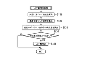
- FIG. 8 is a flowchart showing another example of the vertical movement detection process according to the present embodiment.
- the event detection unit 112 calculates the altitude based on the atmospheric pressure indicated by the atmospheric pressure signal input from the observation signal detection unit 16. When calculating the altitude, the event detection unit 112 uses, for example, the relationship shown in Expression (1).
- h represents an altitude (unit: m).
- P 0 and P represent sea level pressure (unit: hPa) and measurement pressure (unit: hPa), respectively.
- the measured atmospheric pressure is the atmospheric pressure measured by the atmospheric pressure sensor.
- T indicates temperature.
- the terminal device 10 may include a temperature sensor (not shown) for measuring the temperature in the main body 10A.
- a predetermined value for example, 101.25 hPa may be used as the sea level pressure. Thereafter, the process proceeds to step S132.
- Step S132 The event detection unit 112 calculates the vertical velocity by differentiating the calculated altitude. Thereafter, the process proceeds to step S133.
- Step S133 The event detection unit 112 detects a zero cross point of the calculated speed. The event detection unit 112 calculates the difference between the altitude at the immediately preceding zero cross point and the altitude at that time as the amount of movement from the zero cross point. Thereafter, the process proceeds to step S134.
- Step S134 The event detection unit 112 determines whether or not the calculated movement amount is larger than a predetermined movement amount threshold value. When it is determined that the value is larger (YES in step S134), the process proceeds to step S135. When it is determined that it is not large (NO in step S134), the processing shown in FIG. 7 is terminated. (Step S135) The event detection unit 112 determines that vertical movement of the head has been detected as a predetermined event. The event detection unit 112 outputs an event detection signal indicating detection of a predetermined event to the visual information control unit 113 and the auditory information control unit 114, respectively. Thereafter, the process shown in FIG.
- the process shown in FIG. 8 includes, but is not limited to, the event detection unit 112 that converts the atmospheric pressure to a high level in step S131.
- the event detection unit 112 may omit the process of changing the atmospheric pressure to a high degree.
- the terminal device 10 includes the display units 13L and 13R that can display visually-visible visual information on the outside scene.
- the terminal device 10 includes an event detection unit 112 that can detect an event that may cause danger due to visual recognition of visual information.
- the terminal device 10 includes a frame 19F and arms 19L and 19R as mounting parts that can be mounted on the user's head and support the display units 13L and 13R and the event detection unit 112.
- a visual information suppression unit 113 that suppresses the display of visual information on the display units 13L and 13R is provided.
- the event detection unit 112 can detect that the movement amount of the event detection unit 112 is larger than a predetermined movement amount threshold as an event that may cause danger due to visual information visual recognition.
- a predetermined movement amount threshold as an event that may cause danger due to visual information visual recognition.
- the event detection unit 112 can detect a change amount in a predetermined rotation direction as the movement amount of its own unit.
- the event detection unit 112 can detect the movement amount in the vertical direction as the movement amount of its own part.
- the terminal device 10 includes reproduction units 14L and 14R that can reproduce audible auditory information.
- the terminal device 10 suppresses the reproduction of the auditory information to the reproduction units 14L and 14R when an event that may cause danger due to visual information is detected.
- the reproduction of auditory information to the reproduction units 14L and 14R is suppressed. Therefore, the user wearing the terminal device 10 can more accurately grasp the surrounding environment by listening to surrounding sounds, for example, in a situation where the user cannot rely entirely on the sight, such as outside the visual field range of the user. .
- the event detection unit 112 detects the approach of an object as a predetermined event based on the observation signal input from the observation signal detection unit 16.
- the observation signal detection unit 16 includes, for example, a sound collection unit (microphone) that records incoming sound.
- the sound collection unit generates an acoustic signal indicating the recorded sound, and outputs the generated acoustic signal to the event detection unit 112 as an observation signal.
- the event detection unit 112 calculates an acoustic feature amount and power (volume) for each frame (for example, 10 ms to 50 ms) from the acoustic signal input from the observation signal detection unit 16.
- the acoustic feature amount is, for example, a set of a mel frequency cepstrum and a fundamental frequency.
- the storage unit 17 stores sound source data in advance.
- the sound source data includes a time series of acoustic feature amounts within a predetermined time (for example, 100 ms to 1 s) for each sound source.
- the sound source for example, an operation sound of a vehicle such as a passenger car, a truck, or a bicycle, that is, a traveling sound generated by traveling or a warning sound generated by a driver's instruction may be used.
- the event detection unit 112 calculates, for each sound source, an index value of the similarity between the time series of the acoustic feature amount including the calculated acoustic feature amount and the time series of the acoustic feature amount indicated by the sound source data.
- the similarity is, for example, the Euclidean distance.
- the Euclidean distance is an index value indicating the magnitude of the difference between two acoustic feature quantities that are vector quantities.
- the Euclidean distance is an index value indicating that the greater the value, the lower the similarity, and the smaller the value, the higher the similarity.
- the event detection unit 112 determines whether or not the similarity related to the sound source having the highest calculated similarity is higher than a predetermined similarity.
- the event detection unit 112 specifies the sound source (sound source identification).
- the event detection unit 112 determines that the approach of the object serving as the sound source has been detected. For example, when the sound source is a running sound of the vehicle, the event detection unit 112 determines the approach of the vehicle.
- the event detection unit 112 outputs an event detection signal indicating the approach of an object as a predetermined event to the visual information control unit 113 and the auditory information control unit 114, respectively.
- the event detection unit 112 determines that the sound source cannot be specified when the similarity related to the sound source having the highest calculated similarity is determined to be equal to or lower than the predetermined similarity. Even when it is determined that the sound source can be specified, the event detection unit 112 determines that the approach of the object is not detected when the power does not change or decreases with time.
- FIG. 9 is a flowchart illustrating an example of the object approach detection process according to the present embodiment.
- the event detection unit 112 acquires an acoustic signal from the observation signal detection unit 16, and calculates a power and an acoustic feature amount for each frame of the acquired acoustic signal. Thereafter, the process proceeds to step S142.
- the event detection unit 112 calculates the similarity between the calculated time series of acoustic feature quantities and the time series of acoustic feature quantities for each sound source, and the similarity of the sound source with the highest calculated similarity is predetermined. It is determined whether or not it is higher than the similarity threshold.
- the event detection unit 112 When determining that the degree of similarity is higher than the predetermined threshold, the event detection unit 112 identifies the sound source (YES in step S142), and proceeds to the process of step S143. When determining that the similarity is equal to or less than the predetermined threshold, the event detection unit 112 determines that the sound source cannot be specified (NO in step S142), and ends the process illustrated in FIG.
- Step S143 The event detection unit 112 determines whether or not the power increases with time. When it determines with increasing (step S143 YES), it progresses to the process of step S144. When it determines with not increasing (step S143 NO), the process shown in FIG. 9 is complete
- the detection of an object that approaches the terminal device 10 as an example of the predetermined event is taken as an example.
- the event detection unit 112 detects an approach to an object that is stationary or sluggish as the terminal device 10 moves. May be. Such an object is, for example, an obstacle placed on the passage. Therefore, the observation signal detection unit 16 and the event detection unit 112 may be configured as an object detection sensor, for example.
- the terminal device 10 includes a signal transmission unit (not shown) on the frame 19F.
- the signal transmission unit is installed at a position and a direction in which a signal can be transmitted within a predetermined viewing angle (for example, 30 ° to 45 °) centered on the front of the user with the terminal device 10 mounted on the user.
- the observation signal detector 16 receives a signal having a component having a wavelength in common with the signal transmitted by the signal transmitter as an observation signal.
- the observation signal detection unit 16 outputs the received observation signal to the event detection unit 112.
- the event detection unit 112 detects the signal level of the observation signal input from the observation signal detection unit 16.
- the event detection unit 112 determines that an object is detected within a predetermined range from the own unit when the level difference between the signal level of the detected observation signal and the signal level of the transmission signal is smaller than a predetermined level difference threshold. To do.
- the event detection unit 112 may detect the propagation time from the transmission of the transmission signal to the arrival of the observation signal.
- the event detection unit 112 may detect a phase difference as a physical quantity indicating the propagation time. When the detected propagation time is smaller than the predetermined propagation time, the event detection unit 112 determines that an object has been detected within a predetermined range from the own part.
- the predetermined range is a range within the viewing angle of the signal transmission unit and the distance from the observation signal detection unit 16 is smaller than the predetermined distance.
- the event detection unit 112 outputs an event detection signal indicating approach to an object as a predetermined event to the visual information control unit 113 and the auditory information control unit 114, respectively.
- FIG. 10 is a flowchart illustrating another example of the object approach detection process according to the present embodiment.
- Step S151 The signal transmission unit transmits the transmission signal within a predetermined viewing angle. Thereafter, the process proceeds to step S152.
- Step S152 The event detection unit 112 acquires an observation signal from the observation signal detection unit 16. Thereafter, the process proceeds to step S153.
- Step S153 The event detection unit 112 detects the signal level of the observation signal and determines whether the level difference from the signal level of the transmission signal is smaller than a predetermined level difference threshold. When it determines with it being small (step S153 YES), it progresses to the process of step S154. When it determines with it not being small (step S153 NO), the process shown in FIG. 10 is complete
- the event detection unit 112 detects the approach of an object as an event that may cause danger due to visual information visual recognition.
- the approach of an object is detected, display of visual information on the display units 13L and 13R is suppressed.
- the user can confirm the approach of the object by visually recognizing the outside scene. Therefore, the user can use the terminal device 10 safely.
- the event detection unit 112 determines the type of the sound source using the acquired acoustic signal, and detects the approach of the vehicle based on the signal level of the acoustic signal when the determined type of the sound source is the operation sound of the vehicle. With this configuration, when the approach of the vehicle is detected, display of visual information on the display units 13L and 13R is suppressed. At that time, the user can visually recognize the outside scene and confirm the approach of the vehicle, and can avoid contact with the vehicle.
- the terminal device 10 includes a signal transmission unit that transmits a transmission signal.
- the event detection unit 112 detects an object based on the level difference between the received observation signal and the transmission signal or the propagation time from transmission to reception.
- the event detection unit 112 detects entry into a predetermined area (region) as a predetermined event based on the observation signal input from the observation signal detection unit 16.
- the area is an area where a user wearing the terminal device 10 may be in danger when visually recognizing visual information displayed on the display units 13L and 13R.
- Such an area is, for example, a stepped, inclined or uneven space, a narrow space, a space where various objects are installed in the vicinity, a driver's seat of a vehicle, and the like.
- the observation signal detector 16 includes, for example, a receiver that receives radio waves in a predetermined frequency band.
- the observation signal detection unit 16 outputs the received signal received as an observation signal to the event detection unit 112.
- the receiving unit 181 of the communication unit 18 may be used.
- the event detection unit 112 determines whether the signal level of the observation signal input from the observation signal detection unit 16 is higher than a predetermined signal level. When the signal level of the observation signal is higher than the signal level of the process, the event detection unit 112 demodulates the observation signal and tries to detect the broadcast information conveyed.
- the broadcast information is information for a base station apparatus configuring the wireless network to broadcast the network.
- the broadcast information is, for example, an SSID (Service Set ⁇ ⁇ identifier) transmitted from the radio base station using a beacon defined in IEEE802.15.
- the event detection unit 112 determines, as a predetermined area, the entry of its own device into an area (coverage) that can be communicated from the radio base station.
- the event detection unit 112 outputs an event detection signal indicating entry into a predetermined area as a predetermined event to the visual information control unit 113 and the auditory information control unit 114, respectively. When the event detection unit 112 does not detect the notification information, the event detection unit 112 determines that the own device has not entered the predetermined area.
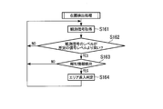
- FIG. 11 is a flowchart illustrating an example of a location detection process according to the present embodiment.
- the event detection unit 112 acquires an observation signal from the observation signal detection unit 16. Thereafter, the process proceeds to step S162.
- the event detection unit 112 detects the signal level of the observation signal, and determines whether or not the detected signal level is higher than a predetermined signal level threshold. When it determines with it being high (step S162 YES), it progresses to the process of step S163. When it determines with not being high (step S162 NO), the process shown in FIG. 11 is complete
- Step S163 The event detection unit 112 tries to detect the notification information carried by the observation signal, and when the notification information is detected (YES in Step S163), the process proceeds to Step S164.
- Step S164 The event detection unit 112 determines that the own device has entered a predetermined area.
- the event detection unit 112 outputs an event detection signal indicating entry into a predetermined area as a predetermined event to the visual information control unit 113 and the auditory information control unit 114, respectively. Then, the process shown in FIG. 11 is complete
- the terminal apparatus 10 enters the predetermined area.
- the case where it determined with having been made was taken as an example, it is not restricted to this.
- the conveyance and detection of the notification information may be omitted.
- the event detection unit 112 has exemplified the case where the signal level of the radio wave is used when determining whether or not the vehicle has entered the predetermined area, the present invention is not limited to this.
- infrared rays, visible light, ultrasonic waves, or the like may be used instead of radio waves.
- the event detection unit 112 detects an entry into a predetermined area as an event that may cause danger due to visual information visual recognition.
- a predetermined area such as a space with a step, slope or unevenness, a narrow space, a space where various objects are installed in the vicinity, a driver's seat of a vehicle.
- the user can grasp the surrounding environment by visually recognizing the outside scene. Therefore, the user can use the terminal device 10 safely.
- the event detection unit 112 according to the present embodiment further detects the line-of-sight directions of the left and right eyes of the user wearing the terminal device 10.
- the visual information control unit 113 suppresses the visual information of a portion presented within a predetermined range from the line-of-sight direction among the visual information acquired from the function control unit 111.
- FIG. 12 is a block diagram illustrating an example of a functional configuration of the terminal device 10 according to the present embodiment.
- the terminal device 10 further includes a second observation signal detection unit 26.
- the second observation signal detection unit 26 detects the second observation signal and outputs the detected second observation signal to the event detection unit 112.
- the second observation signal is used for detecting the line-of-sight direction of the user wearing the terminal device 10 in the line-of-sight detection unit 112A (described later).
- the type of the second observation signal depends on the gaze direction detection method.
- the event detection unit 112 further includes a line-of-sight detection unit 112A.
- the line-of-sight detection unit 112 ⁇ / b> A detects the user's line-of-sight direction based on the second observation signal input from the second observation signal detection unit 26. For example, an image signal indicating an image of each of the left and right eyes of the user may be input to the line-of-sight detection unit 112A as the second observation signal.
- the second observation signal detection unit 26 includes an imaging unit (not shown) for capturing images of the left and right eyes of the user. The imaging unit is arranged in a position and orientation in which the visual field includes the area of each of the left and right eyes of the user in a state where the terminal device 10 is mounted.
- the line-of-sight detection unit 112A detects the positions of the eyes and iris using a known image recognition technique for the left and right eye images indicated by the image signal.
- the line-of-sight detection unit 112A calculates the line-of-sight directions of the left and right eyes using a known line-of-sight detection technique based on the detected positional relationship between the eye and iris.
- the line-of-sight detection unit 112 ⁇ / b> A outputs a line-of-sight signal indicating the calculated line-of-sight direction to the visual information acquisition unit 113.
- a myoelectric potential signal indicating myoelectric potential around the left and right eyes of the user may be input to the line-of-sight detection unit 112A as the second observation signal.
- the line-of-sight detection unit 112 ⁇ / b> A detects the line-of-sight direction of the user's left and right eyes from the myoelectric potential signal acquired using the EOG (Electro-Oculo-Graph) method for the myoelectric potential signal.
- the second observation signal detection unit 26 includes an electrode plate made of a conductor for detecting a myoelectric potential signal. In the frame 19F, the electrode plate is arranged at a position and an orientation in contact with the periphery of the left and right eyes of the user in a state where the terminal device 10 is mounted.
- the visual information control unit 113 receives a visual line signal from the visual line detection unit 112A.
- the visual information control unit 113 determines, for each of the left and right eyes, a region within a predetermined range from the line-of-sight direction indicated by the line-of-sight signal among the display regions of the display units 13L and 13R. More specifically, the visual information control unit 113 determines an intersection between a straight line from the fovea of each eye of the user wearing the terminal device 10 in the eye gaze direction and the display area of each of the display units 13L and 13R.
- a region within a predetermined range (for example, 3 ° to 10 °) from the intersection is defined as a display suppression region.
- the fovea is a part where light coming from the pupil concentrates.
- the visual information control unit 113 suppresses the visual information in the left and right display suppression regions for each of the left visual information and the right visual information, and does not suppress the visual information of other portions.
- the visual information control unit 113 may lower the luminance gain acting on the luminance value below a predetermined gain, or may set the luminance gain to zero.
- the visual information control unit 113 may move the visual information in the display suppression area out of the display suppression area among the acquired left visual information and right visual information. Good.
- the visual information control unit 113 outputs an image signal indicating left visual information and an image signal indicating right visual information obtained by suppressing the visual information in the display suppression region to the display units 13L and 13R, respectively.
- FIG. 13 is a flowchart illustrating an example of the presentation information suppression process according to the present embodiment.
- the process shown in FIG. 13 includes steps S101 to S104, S106, and S201 to 203.
- the processes in steps S101 to S104 and S106 are the same as the processes in steps S101 to S104 and S106 in FIG.
- step S201 when the event detection unit 112 determines that a predetermined event is detected based on the observation signal input from the observation signal detection unit 16 (YES in step S104), the process proceeds to step S201.
- the line-of-sight detection unit 112A detects the line-of-sight direction of each eye of the user wearing the terminal device 10, based on the second observation signal input from the second observation signal detection unit 26.
- the line-of-sight detection unit 112 ⁇ / b> A outputs a line-of-sight signal indicating the detected line-of-sight direction to the visual information acquisition unit 113. Thereafter, the process proceeds to step S202.
- Step S202 The visual information control unit 113 determines an area within a predetermined range from the line-of-sight direction as a display suppression area in the visual information display area. Thereafter, the process proceeds to step S203.
- Step S203 The visual information control unit 113 suppresses the output of the visual information to the display units 13L and 13R in the left and right display suppression regions for each of the left visual information and the right visual information. To do. Thereafter, the process proceeds to step S106.
- the event detection unit 112 detects the line-of-sight direction of the user wearing the terminal device 10.
- the visual information control unit 113 suppresses display of visual information in a display suppression area within a predetermined range from the detected line-of-sight direction.
- the display of the visual information is suppressed in the display suppression area including the area where the user is staring among the display areas of the visual information, and the display of the visual information outside the display suppression area is maintained. Therefore, the user can recognize the surrounding environment more accurately by visually recognizing the outside scene through the display suppression area, and can visually recognize the visual information in the area not staring. Therefore, the loss of visual information presented to the user can be reduced, and the terminal device 10 can be used safely.
- the event detection unit 112 may detect any one or a plurality of predetermined events among the predetermined events described in the first to third embodiments, and may not detect other predetermined events. .
- the observation signal detection part 16 should just be able to detect the observation signal used for each event detection.
- a part of the configuration of the terminal device 10 may be omitted.
- the reproduction units 14L and 14R and the auditory information control unit 114 may be omitted.
- the communication unit 18 may be omitted. As long as various signals can be transmitted to and received from the control unit 11, the command input unit 15 may be separate from the terminal device 10.
- a display unit capable of displaying visually-visible visual information superimposed on an outside scene, a detection unit capable of detecting an event that may cause a danger due to visual recognition of the visual information
- a terminal device comprising: a display unit; a mounting unit that supports the detection unit; and a control unit that suppresses display of visual information on the display unit when the event is detected.
- the detection unit determines the type of the sound source using the acquired acoustic signal, and when the determined type of the sound source is a running sound of the vehicle, the detection unit detects the approach of the object based on the signal level of the acoustic signal.
- the terminal device of (5) to detect.
- a signal transmission unit that transmits a transmission signal is provided, and the detection unit detects the object based on a level difference between a reception signal and the transmission signal or a time difference from transmission of the transmission signal to reception of the reception signal.
- the detection unit detects the visual line direction of the user, and the control unit suppresses display of the visual information within a predetermined range from the visual line direction. Terminal device.
- a reproduction unit capable of reproducing audible auditory information is provided, and the control unit suppresses reproduction of auditory information to the reproduction unit when the event is detected (1) to (9) One of the terminal devices.
- a display unit capable of displaying visible visual information superimposed on an outside scene, a detection unit capable of detecting an event that may cause a danger due to visual recognition of the visual information, and a head mounted on a user's head,
- An operation method of a terminal device comprising a display unit and a mounting unit that supports the detection unit, the method comprising: a control process for suppressing display of visual information on the display unit when the event is detected How it works.
- a display unit capable of displaying visually-visible visual information superimposed on an outside scene
- a detection unit capable of detecting an event that may cause a danger due to visual recognition of the visual information
- a control device for causing a computer of a terminal device including a display unit and a mounting unit that supports the detection unit to execute a control procedure for suppressing display of visual information on the display unit when the event is detected program.
- a part of the terminal device 10, for example, the function control unit 111, the event detection unit 112, the visual information control unit 113, and the auditory information control unit 114 may be realized by a computer.
- the program for realizing the control function may be recorded on a computer-readable recording medium, and the program recorded on the recording medium may be read by the computer system and executed.
- LSI Large Scale Integration
- the method of circuit integration is not limited to LSI's, and implementation using dedicated circuitry or general purpose processors is also possible. Further, in the case where an integrated circuit technology that replaces LSI appears due to progress in semiconductor technology, an integrated circuit based on the technology may be used.
- One embodiment of the present invention is used in, for example, a communication system, a communication device (for example, a mobile phone device, a base station device, a wireless LAN device, or a sensor device), an integrated circuit (for example, a communication chip), a program, or the like. be able to.
- a communication device for example, a mobile phone device, a base station device, a wireless LAN device, or a sensor device
- an integrated circuit for example, a communication chip
- a program or the like.
Landscapes
- Engineering & Computer Science (AREA)
- Physics & Mathematics (AREA)
- General Physics & Mathematics (AREA)
- Theoretical Computer Science (AREA)
- Computer Hardware Design (AREA)
- Multimedia (AREA)
- Optics & Photonics (AREA)
- Signal Processing (AREA)
- Computational Linguistics (AREA)
- Software Systems (AREA)
- Stereophonic System (AREA)
- User Interface Of Digital Computer (AREA)
Abstract
L'invention concerne une unité d'affichage permettant d'afficher des informations visuelles visibles superposées sur une scène extérieure. Une unité de détection permet de détecter des événements pouvant donner lieu à un danger par la visualisation des informations visuelles. Une unité vestimentaire peut être portée sur la tête d'un utilisateur et soutient l'unité d'affichage et l'unité de détection. Une unité de commande supprime l'affichage d'informations visuelles par l'unité d'affichage lorsque l'événement est détecté. Un mode de réalisation de la présente invention peut être mis en œuvre soit par un dispositif terminal, soit par un procédé de communication, soit par un programme.
Priority Applications (1)
| Application Number | Priority Date | Filing Date | Title |
|---|---|---|---|
| US16/344,291 US20190271843A1 (en) | 2016-11-02 | 2017-11-02 | Terminal apparatus, operating method, and program |
Applications Claiming Priority (2)
| Application Number | Priority Date | Filing Date | Title |
|---|---|---|---|
| JP2016215411 | 2016-11-02 | ||
| JP2016-215411 | 2016-11-02 |
Publications (1)
| Publication Number | Publication Date |
|---|---|
| WO2018084227A1 true WO2018084227A1 (fr) | 2018-05-11 |
Family
ID=62076738
Family Applications (1)
| Application Number | Title | Priority Date | Filing Date |
|---|---|---|---|
| PCT/JP2017/039664 Ceased WO2018084227A1 (fr) | 2016-11-02 | 2017-11-02 | Dispositif terminal, procédé d'exploitation et programme |
Country Status (2)
| Country | Link |
|---|---|
| US (1) | US20190271843A1 (fr) |
| WO (1) | WO2018084227A1 (fr) |
Citations (7)
| Publication number | Priority date | Publication date | Assignee | Title |
|---|---|---|---|---|
| JPH05304646A (ja) * | 1992-04-24 | 1993-11-16 | Sony Corp | 映像表示装置 |
| JPH10504917A (ja) * | 1995-05-25 | 1998-05-12 | フィリップス エレクトロニクス ネムローゼ フェンノートシャップ | ヘッドマウントディスプレイ用衝突警告システム |
| JP2005165778A (ja) * | 2003-12-03 | 2005-06-23 | Canon Inc | 頭部装着型表示装置、及びその制御方法 |
| JP2005252734A (ja) * | 2004-03-04 | 2005-09-15 | Olympus Corp | 頭部装着型カメラ |
| JP2012203128A (ja) * | 2011-03-24 | 2012-10-22 | Seiko Epson Corp | 頭部装着型表示装置および頭部装着型表示装置の制御方法 |
| WO2015125364A1 (fr) * | 2014-02-21 | 2015-08-27 | ソニー株式会社 | Appareil électronique et procédé de fourniture d'image |
| JP2015213226A (ja) * | 2014-05-02 | 2015-11-26 | コニカミノルタ株式会社 | ウエアラブルディスプレイ及びその表示制御プログラム |
Family Cites Families (3)
| Publication number | Priority date | Publication date | Assignee | Title |
|---|---|---|---|---|
| US7164117B2 (en) * | 1992-05-05 | 2007-01-16 | Automotive Technologies International, Inc. | Vehicular restraint system control system and method using multiple optical imagers |
| US9219901B2 (en) * | 2012-06-19 | 2015-12-22 | Qualcomm Incorporated | Reactive user interface for head-mounted display |
| KR20160016907A (ko) * | 2013-05-29 | 2016-02-15 | 미쓰비시덴키 가부시키가이샤 | 정보 표시 장치 |
-
2017
- 2017-11-02 WO PCT/JP2017/039664 patent/WO2018084227A1/fr not_active Ceased
- 2017-11-02 US US16/344,291 patent/US20190271843A1/en not_active Abandoned
Patent Citations (7)
| Publication number | Priority date | Publication date | Assignee | Title |
|---|---|---|---|---|
| JPH05304646A (ja) * | 1992-04-24 | 1993-11-16 | Sony Corp | 映像表示装置 |
| JPH10504917A (ja) * | 1995-05-25 | 1998-05-12 | フィリップス エレクトロニクス ネムローゼ フェンノートシャップ | ヘッドマウントディスプレイ用衝突警告システム |
| JP2005165778A (ja) * | 2003-12-03 | 2005-06-23 | Canon Inc | 頭部装着型表示装置、及びその制御方法 |
| JP2005252734A (ja) * | 2004-03-04 | 2005-09-15 | Olympus Corp | 頭部装着型カメラ |
| JP2012203128A (ja) * | 2011-03-24 | 2012-10-22 | Seiko Epson Corp | 頭部装着型表示装置および頭部装着型表示装置の制御方法 |
| WO2015125364A1 (fr) * | 2014-02-21 | 2015-08-27 | ソニー株式会社 | Appareil électronique et procédé de fourniture d'image |
| JP2015213226A (ja) * | 2014-05-02 | 2015-11-26 | コニカミノルタ株式会社 | ウエアラブルディスプレイ及びその表示制御プログラム |
Also Published As
| Publication number | Publication date |
|---|---|
| US20190271843A1 (en) | 2019-09-05 |
Similar Documents
| Publication | Publication Date | Title |
|---|---|---|
| US12322368B2 (en) | Adaptive ANC based on environmental triggers | |
| US11647352B2 (en) | Head to headset rotation transform estimation for head pose tracking in spatial audio applications | |
| US11675423B2 (en) | User posture change detection for head pose tracking in spatial audio applications | |
| US10795445B2 (en) | Methods, devices, and systems for determining contact on a user of a virtual reality and/or augmented reality device | |
| US12108237B2 (en) | Head tracking correlated motion detection for spatial audio applications | |
| US20210400420A1 (en) | Inertially stable virtual auditory space for spatial audio applications | |
| US11482237B2 (en) | Method and terminal for reconstructing speech signal, and computer storage medium | |
| US11599189B2 (en) | Head orientation tracking | |
| US11327317B2 (en) | Information processing apparatus and information processing method | |
| JP7468506B2 (ja) | 情報処理装置、情報処理方法、及び記録媒体 | |
| WO2020070839A1 (fr) | Visiocasque et système de visiocasque | |
| CN115151858A (zh) | 可集成于眼镜框的助听系统 | |
| JP6190497B1 (ja) | 情報処理方法及び当該情報処理方法をコンピュータに実行させるためのプログラム | |
| EP4381482A1 (fr) | Audio 3d pour la détection d'objets dans des zones de danger autour de joueurs de rv | |
| JP7065353B2 (ja) | ヘッドマウントディスプレイ及びその制御方法 | |
| WO2017007643A1 (fr) | Systèmes et procédés fournissant des indications non intrusives sur des obstacles | |
| JP7846633B2 (ja) | エンタテインメントシステムおよびロボット | |
| US11240482B2 (en) | Information processing device, information processing method, and computer program | |
| CN110998673A (zh) | 信息处理装置、信息处理方法和计算机程序 | |
| US20240295735A1 (en) | System to detect add-on prescription lenses to vr hmds with eye tracking | |
| US20190271843A1 (en) | Terminal apparatus, operating method, and program | |
| US11487355B2 (en) | Information processing apparatus and information processing method | |
| WO2022149497A1 (fr) | Dispositif de traitement d'informations, procédé de traitement d'informations et programme informatique | |
| CN223068038U (zh) | 一种智能头盔及智能头盔远程协同系统 | |
| WO2024134736A1 (fr) | Dispositif de type visiocasque et procédé de commande de son stéréophonique |
Legal Events
| Date | Code | Title | Description |
|---|---|---|---|
| 121 | Ep: the epo has been informed by wipo that ep was designated in this application |
Ref document number: 17867171 Country of ref document: EP Kind code of ref document: A1 |
|
| NENP | Non-entry into the national phase |
Ref country code: DE |
|
| 122 | Ep: pct application non-entry in european phase |
Ref document number: 17867171 Country of ref document: EP Kind code of ref document: A1 |
|
| NENP | Non-entry into the national phase |
Ref country code: JP |