WO2018088414A1 - 軸受装置の冷却構造 - Google Patents
軸受装置の冷却構造 Download PDFInfo
- Publication number
- WO2018088414A1 WO2018088414A1 PCT/JP2017/040200 JP2017040200W WO2018088414A1 WO 2018088414 A1 WO2018088414 A1 WO 2018088414A1 JP 2017040200 W JP2017040200 W JP 2017040200W WO 2018088414 A1 WO2018088414 A1 WO 2018088414A1
- Authority
- WO
- WIPO (PCT)
- Prior art keywords
- ring spacer
- outer ring
- bearing
- compressed air
- inner ring
- Prior art date
- Legal status (The legal status is an assumption and is not a legal conclusion. Google has not performed a legal analysis and makes no representation as to the accuracy of the status listed.)
- Ceased
Links
Images







Classifications
-
- F—MECHANICAL ENGINEERING; LIGHTING; HEATING; WEAPONS; BLASTING
- F16—ENGINEERING ELEMENTS AND UNITS; GENERAL MEASURES FOR PRODUCING AND MAINTAINING EFFECTIVE FUNCTIONING OF MACHINES OR INSTALLATIONS; THERMAL INSULATION IN GENERAL
- F16C—SHAFTS; FLEXIBLE SHAFTS; ELEMENTS OR CRANKSHAFT MECHANISMS; ROTARY BODIES OTHER THAN GEARING ELEMENTS; BEARINGS
- F16C19/00—Bearings with rolling contact, for exclusively rotary movement
- F16C19/54—Systems consisting of a plurality of bearings with rolling friction
- F16C19/546—Systems with spaced apart rolling bearings including at least one angular contact bearing
-
- B—PERFORMING OPERATIONS; TRANSPORTING
- B23—MACHINE TOOLS; METAL-WORKING NOT OTHERWISE PROVIDED FOR
- B23Q—DETAILS, COMPONENTS, OR ACCESSORIES FOR MACHINE TOOLS, e.g. ARRANGEMENTS FOR COPYING OR CONTROLLING; MACHINE TOOLS IN GENERAL CHARACTERISED BY THE CONSTRUCTION OF PARTICULAR DETAILS OR COMPONENTS; COMBINATIONS OR ASSOCIATIONS OF METAL-WORKING MACHINES, NOT DIRECTED TO A PARTICULAR RESULT
- B23Q11/00—Accessories fitted to machine tools for keeping tools or parts of the machine in good working condition or for cooling work; Safety devices specially combined with or arranged in, or specially adapted for use in connection with, machine tools
- B23Q11/12—Arrangements for cooling or lubricating parts of the machine
-
- B—PERFORMING OPERATIONS; TRANSPORTING
- B23—MACHINE TOOLS; METAL-WORKING NOT OTHERWISE PROVIDED FOR
- B23Q—DETAILS, COMPONENTS, OR ACCESSORIES FOR MACHINE TOOLS, e.g. ARRANGEMENTS FOR COPYING OR CONTROLLING; MACHINE TOOLS IN GENERAL CHARACTERISED BY THE CONSTRUCTION OF PARTICULAR DETAILS OR COMPONENTS; COMBINATIONS OR ASSOCIATIONS OF METAL-WORKING MACHINES, NOT DIRECTED TO A PARTICULAR RESULT
- B23Q11/00—Accessories fitted to machine tools for keeping tools or parts of the machine in good working condition or for cooling work; Safety devices specially combined with or arranged in, or specially adapted for use in connection with, machine tools
- B23Q11/12—Arrangements for cooling or lubricating parts of the machine
- B23Q11/121—Arrangements for cooling or lubricating parts of the machine with lubricating effect for reducing friction
- B23Q11/123—Arrangements for cooling or lubricating parts of the machine with lubricating effect for reducing friction for lubricating spindle bearings
-
- B—PERFORMING OPERATIONS; TRANSPORTING
- B23—MACHINE TOOLS; METAL-WORKING NOT OTHERWISE PROVIDED FOR
- B23Q—DETAILS, COMPONENTS, OR ACCESSORIES FOR MACHINE TOOLS, e.g. ARRANGEMENTS FOR COPYING OR CONTROLLING; MACHINE TOOLS IN GENERAL CHARACTERISED BY THE CONSTRUCTION OF PARTICULAR DETAILS OR COMPONENTS; COMBINATIONS OR ASSOCIATIONS OF METAL-WORKING MACHINES, NOT DIRECTED TO A PARTICULAR RESULT
- B23Q17/00—Arrangements for observing, indicating or measuring on machine tools
-
- F—MECHANICAL ENGINEERING; LIGHTING; HEATING; WEAPONS; BLASTING
- F16—ENGINEERING ELEMENTS AND UNITS; GENERAL MEASURES FOR PRODUCING AND MAINTAINING EFFECTIVE FUNCTIONING OF MACHINES OR INSTALLATIONS; THERMAL INSULATION IN GENERAL
- F16C—SHAFTS; FLEXIBLE SHAFTS; ELEMENTS OR CRANKSHAFT MECHANISMS; ROTARY BODIES OTHER THAN GEARING ELEMENTS; BEARINGS
- F16C19/00—Bearings with rolling contact, for exclusively rotary movement
- F16C19/02—Bearings with rolling contact, for exclusively rotary movement with bearing balls essentially of the same size in one or more circular rows
- F16C19/14—Bearings with rolling contact, for exclusively rotary movement with bearing balls essentially of the same size in one or more circular rows for both radial and axial load
- F16C19/18—Bearings with rolling contact, for exclusively rotary movement with bearing balls essentially of the same size in one or more circular rows for both radial and axial load with two or more rows of balls
-
- F—MECHANICAL ENGINEERING; LIGHTING; HEATING; WEAPONS; BLASTING
- F16—ENGINEERING ELEMENTS AND UNITS; GENERAL MEASURES FOR PRODUCING AND MAINTAINING EFFECTIVE FUNCTIONING OF MACHINES OR INSTALLATIONS; THERMAL INSULATION IN GENERAL
- F16C—SHAFTS; FLEXIBLE SHAFTS; ELEMENTS OR CRANKSHAFT MECHANISMS; ROTARY BODIES OTHER THAN GEARING ELEMENTS; BEARINGS
- F16C19/00—Bearings with rolling contact, for exclusively rotary movement
- F16C19/52—Bearings with rolling contact, for exclusively rotary movement with devices affected by abnormal or undesired conditions
- F16C19/525—Bearings with rolling contact, for exclusively rotary movement with devices affected by abnormal or undesired conditions related to temperature and heat, e.g. insulation
-
- F—MECHANICAL ENGINEERING; LIGHTING; HEATING; WEAPONS; BLASTING
- F16—ENGINEERING ELEMENTS AND UNITS; GENERAL MEASURES FOR PRODUCING AND MAINTAINING EFFECTIVE FUNCTIONING OF MACHINES OR INSTALLATIONS; THERMAL INSULATION IN GENERAL
- F16C—SHAFTS; FLEXIBLE SHAFTS; ELEMENTS OR CRANKSHAFT MECHANISMS; ROTARY BODIES OTHER THAN GEARING ELEMENTS; BEARINGS
- F16C33/00—Parts of bearings; Special methods for making bearings or parts thereof
- F16C33/30—Parts of ball or roller bearings
- F16C33/58—Raceways; Race rings
-
- F—MECHANICAL ENGINEERING; LIGHTING; HEATING; WEAPONS; BLASTING
- F16—ENGINEERING ELEMENTS AND UNITS; GENERAL MEASURES FOR PRODUCING AND MAINTAINING EFFECTIVE FUNCTIONING OF MACHINES OR INSTALLATIONS; THERMAL INSULATION IN GENERAL
- F16C—SHAFTS; FLEXIBLE SHAFTS; ELEMENTS OR CRANKSHAFT MECHANISMS; ROTARY BODIES OTHER THAN GEARING ELEMENTS; BEARINGS
- F16C33/00—Parts of bearings; Special methods for making bearings or parts thereof
- F16C33/30—Parts of ball or roller bearings
- F16C33/66—Special parts or details in view of lubrication
- F16C33/6637—Special parts or details in view of lubrication with liquid lubricant
- F16C33/6659—Details of supply of the liquid to the bearing, e.g. passages or nozzles
-
- F—MECHANICAL ENGINEERING; LIGHTING; HEATING; WEAPONS; BLASTING
- F16—ENGINEERING ELEMENTS AND UNITS; GENERAL MEASURES FOR PRODUCING AND MAINTAINING EFFECTIVE FUNCTIONING OF MACHINES OR INSTALLATIONS; THERMAL INSULATION IN GENERAL
- F16C—SHAFTS; FLEXIBLE SHAFTS; ELEMENTS OR CRANKSHAFT MECHANISMS; ROTARY BODIES OTHER THAN GEARING ELEMENTS; BEARINGS
- F16C33/00—Parts of bearings; Special methods for making bearings or parts thereof
- F16C33/30—Parts of ball or roller bearings
- F16C33/66—Special parts or details in view of lubrication
- F16C33/6637—Special parts or details in view of lubrication with liquid lubricant
- F16C33/6659—Details of supply of the liquid to the bearing, e.g. passages or nozzles
- F16C33/667—Details of supply of the liquid to the bearing, e.g. passages or nozzles related to conditioning, e.g. cooling, filtering
-
- F—MECHANICAL ENGINEERING; LIGHTING; HEATING; WEAPONS; BLASTING
- F16—ENGINEERING ELEMENTS AND UNITS; GENERAL MEASURES FOR PRODUCING AND MAINTAINING EFFECTIVE FUNCTIONING OF MACHINES OR INSTALLATIONS; THERMAL INSULATION IN GENERAL
- F16C—SHAFTS; FLEXIBLE SHAFTS; ELEMENTS OR CRANKSHAFT MECHANISMS; ROTARY BODIES OTHER THAN GEARING ELEMENTS; BEARINGS
- F16C37/00—Cooling of bearings
- F16C37/007—Cooling of bearings of rolling bearings
-
- F—MECHANICAL ENGINEERING; LIGHTING; HEATING; WEAPONS; BLASTING
- F16—ENGINEERING ELEMENTS AND UNITS; GENERAL MEASURES FOR PRODUCING AND MAINTAINING EFFECTIVE FUNCTIONING OF MACHINES OR INSTALLATIONS; THERMAL INSULATION IN GENERAL
- F16C—SHAFTS; FLEXIBLE SHAFTS; ELEMENTS OR CRANKSHAFT MECHANISMS; ROTARY BODIES OTHER THAN GEARING ELEMENTS; BEARINGS
- F16C41/00—Other accessories, e.g. devices integrated in the bearing not relating to the bearing function as such
- F16C41/007—Encoders, e.g. parts with a plurality of alternating magnetic poles
-
- B—PERFORMING OPERATIONS; TRANSPORTING
- B23—MACHINE TOOLS; METAL-WORKING NOT OTHERWISE PROVIDED FOR
- B23Q—DETAILS, COMPONENTS, OR ACCESSORIES FOR MACHINE TOOLS, e.g. ARRANGEMENTS FOR COPYING OR CONTROLLING; MACHINE TOOLS IN GENERAL CHARACTERISED BY THE CONSTRUCTION OF PARTICULAR DETAILS OR COMPONENTS; COMBINATIONS OR ASSOCIATIONS OF METAL-WORKING MACHINES, NOT DIRECTED TO A PARTICULAR RESULT
- B23Q17/00—Arrangements for observing, indicating or measuring on machine tools
- B23Q17/09—Arrangements for observing, indicating or measuring on machine tools for indicating or measuring cutting pressure or for determining cutting-tool condition, e.g. cutting ability, load on tool
- B23Q17/0952—Arrangements for observing, indicating or measuring on machine tools for indicating or measuring cutting pressure or for determining cutting-tool condition, e.g. cutting ability, load on tool during machining
- B23Q17/0985—Arrangements for observing, indicating or measuring on machine tools for indicating or measuring cutting pressure or for determining cutting-tool condition, e.g. cutting ability, load on tool during machining by measuring temperature
-
- F—MECHANICAL ENGINEERING; LIGHTING; HEATING; WEAPONS; BLASTING
- F16—ENGINEERING ELEMENTS AND UNITS; GENERAL MEASURES FOR PRODUCING AND MAINTAINING EFFECTIVE FUNCTIONING OF MACHINES OR INSTALLATIONS; THERMAL INSULATION IN GENERAL
- F16C—SHAFTS; FLEXIBLE SHAFTS; ELEMENTS OR CRANKSHAFT MECHANISMS; ROTARY BODIES OTHER THAN GEARING ELEMENTS; BEARINGS
- F16C19/00—Bearings with rolling contact, for exclusively rotary movement
- F16C19/02—Bearings with rolling contact, for exclusively rotary movement with bearing balls essentially of the same size in one or more circular rows
- F16C19/14—Bearings with rolling contact, for exclusively rotary movement with bearing balls essentially of the same size in one or more circular rows for both radial and axial load
- F16C19/18—Bearings with rolling contact, for exclusively rotary movement with bearing balls essentially of the same size in one or more circular rows for both radial and axial load with two or more rows of balls
- F16C19/181—Bearings with rolling contact, for exclusively rotary movement with bearing balls essentially of the same size in one or more circular rows for both radial and axial load with two or more rows of balls with angular contact
- F16C19/183—Bearings with rolling contact, for exclusively rotary movement with bearing balls essentially of the same size in one or more circular rows for both radial and axial load with two or more rows of balls with angular contact with two rows at opposite angles
- F16C19/184—Bearings with rolling contact, for exclusively rotary movement with bearing balls essentially of the same size in one or more circular rows for both radial and axial load with two or more rows of balls with angular contact with two rows at opposite angles in O-arrangement
-
- F—MECHANICAL ENGINEERING; LIGHTING; HEATING; WEAPONS; BLASTING
- F16—ENGINEERING ELEMENTS AND UNITS; GENERAL MEASURES FOR PRODUCING AND MAINTAINING EFFECTIVE FUNCTIONING OF MACHINES OR INSTALLATIONS; THERMAL INSULATION IN GENERAL
- F16C—SHAFTS; FLEXIBLE SHAFTS; ELEMENTS OR CRANKSHAFT MECHANISMS; ROTARY BODIES OTHER THAN GEARING ELEMENTS; BEARINGS
- F16C2233/00—Monitoring condition, e.g. temperature, load, vibration
-
- F—MECHANICAL ENGINEERING; LIGHTING; HEATING; WEAPONS; BLASTING
- F16—ENGINEERING ELEMENTS AND UNITS; GENERAL MEASURES FOR PRODUCING AND MAINTAINING EFFECTIVE FUNCTIONING OF MACHINES OR INSTALLATIONS; THERMAL INSULATION IN GENERAL
- F16C—SHAFTS; FLEXIBLE SHAFTS; ELEMENTS OR CRANKSHAFT MECHANISMS; ROTARY BODIES OTHER THAN GEARING ELEMENTS; BEARINGS
- F16C2322/00—Apparatus used in shaping articles
- F16C2322/39—General buildup of machine tools, e.g. spindles, slides, actuators
-
- F—MECHANICAL ENGINEERING; LIGHTING; HEATING; WEAPONS; BLASTING
- F16—ENGINEERING ELEMENTS AND UNITS; GENERAL MEASURES FOR PRODUCING AND MAINTAINING EFFECTIVE FUNCTIONING OF MACHINES OR INSTALLATIONS; THERMAL INSULATION IN GENERAL
- F16C—SHAFTS; FLEXIBLE SHAFTS; ELEMENTS OR CRANKSHAFT MECHANISMS; ROTARY BODIES OTHER THAN GEARING ELEMENTS; BEARINGS
- F16C35/00—Rigid support of bearing units; Housings, e.g. caps, covers
- F16C35/08—Rigid support of bearing units; Housings, e.g. caps, covers for spindles
- F16C35/12—Rigid support of bearing units; Housings, e.g. caps, covers for spindles with ball or roller bearings
-
- F—MECHANICAL ENGINEERING; LIGHTING; HEATING; WEAPONS; BLASTING
- F16—ENGINEERING ELEMENTS AND UNITS; GENERAL MEASURES FOR PRODUCING AND MAINTAINING EFFECTIVE FUNCTIONING OF MACHINES OR INSTALLATIONS; THERMAL INSULATION IN GENERAL
- F16C—SHAFTS; FLEXIBLE SHAFTS; ELEMENTS OR CRANKSHAFT MECHANISMS; ROTARY BODIES OTHER THAN GEARING ELEMENTS; BEARINGS
- F16C41/00—Other accessories, e.g. devices integrated in the bearing not relating to the bearing function as such
Definitions
- the present invention relates to a cooling structure for a bearing device, for example, a main shaft of a machine tool and a cooling structure for a bearing incorporated in the main shaft.
- an annular recess is provided on the peripheral surface of the outer ring spacer facing the inner ring spacer, an outlet is provided in the recess, an air nozzle is provided, and cooling air is directed toward the peripheral surface of the inner ring spacer.
- a cooling structure for discharging is proposed (Patent Document 2).
- the outer ring spacer is provided with lubricating fluid discharge means for supplying lubricating air oil to the rolling bearings on both sides. According to this configuration, the compressed air is adiabatically expanded by being discharged at a stroke from the narrow nozzle hole into the space formed by the recess. As a result, the flow rate of compressed air increases and the temperature decreases. Therefore, the rotating side spacer is efficiently cooled.
- JP 2000-161375 A Japanese Patent Laying-Open No. 2015-183738
- the object of the present invention is to cool the rolling bearings lined up in three or more rows by air cooling. Even if the operating conditions change variously, it is possible to intensively cool the places where the bearing temperature is high, and the limited compressed air is used. To provide a cooling structure for a bearing device that can be used efficiently.
- an outer ring spacer and an inner ring spacer are interposed between the outer rings and the inner rings of adjacent rolling bearings in the arrangement of the rolling bearings arranged in three or more rows in the axial direction, respectively.
- a cooling structure for a bearing device in which an outer ring spacer is installed on an inner periphery of a housing, and the inner ring and the inner ring spacer are fitted to an outer periphery of a rotating shaft,
- An air nozzle that discharges compressed air to the inner ring spacer facing the plurality of outer ring spacers, a valve that adjusts the compressed air discharged from each of the air nozzles, a control unit that controls the valves, and
- a plurality of temperature measuring means for measuring the temperature of three or more rows of rolling bearings; The control means controls the valve so that compressed air is discharged from an air nozzle selected according to a predetermined rule, using measured values of temperatures measured by the plurality of temperature measuring means.
- the valve is controlled so that the compressed air is discharged from a predetermined air nozzle using the temperature measurement value measured by the temperature measurement means of the rolling bearing of each part. Therefore, even if the operating conditions change variously, it is possible to intensively cool a portion where the bearing temperature is high, and the limited compressed air can be used efficiently.
- the “valve” is a general term for means for opening / closing, switching, or adjusting the flow rate of a compressed air supply path.
- the control means uses the measured value of the temperature measured by the plurality of temperature measuring means, and compressed air is discharged from the air nozzle facing the inner ring spacer adjacent to the rolling bearing having the highest temperature.
- the valve may be controlled as described above.
- Compressed air is discharged to the inner ring spacer.
- the compressed air discharged from the air nozzle is discharged toward the rolling bearings on both sides adjacent to the outer ring spacer.
- One-sided rolling bearing that has exhaust passages on both sides and that is adjacent to the outer ring spacer with compressed air discharged from the air nozzle between any of the other outer ring spacers and the corresponding inner ring spacer. You may make it have the one-side exhaust route discharged
- the outer ring spacer may have lubricating fluid discharge means for supplying lubricating fluid to adjacent rolling bearings.
- the lubricating fluid When the compressed air discharged from the air nozzle and the lubricating fluid flow in the same direction to the rolling bearings on both sides adjacent to the outer ring spacer, the lubricating fluid is promoted by the compressed air by the compressed air on both sides and the inside of the rolling bearing This improves the lubricity fluid penetration and exhaust performance, and improves lubrication reliability.
- the lubricating fluid mixes with the compressed air, and the inside of the rolling bearing Since it is difficult to penetrate the exhaust gas and exhaust performance is lowered, the lubrication reliability is lowered. In such a case, by having the one-side exhaust path, mixed flow can be avoided and lubrication reliability can be ensured.
- the one-side exhaust path is formed between a gap between the outer ring spacer and the inner ring spacer and between the outer ring spacer and the inner ring spacer and has a radial dimension larger than the gap.
- the air nozzle may open to the annular space, and one part of the annular space with respect to the central axis of the air nozzle may have a larger volume than the other part.
- the compressed air discharged from the air nozzle to the annular space is likely to flow into the larger volume portion of the both sides of the annular space with respect to the central axis of the air nozzle. Therefore, a one-side exhaust path that positively discharges compressed air discharged from the air nozzle toward the adjacent one-side rolling bearing can be realized.
- the outer ring spacer having the air nozzle may have a lubricating fluid discharge means for supplying a lubricating fluid containing air and lubricating oil to an adjacent rolling bearing.
- a lubricating fluid discharge means for supplying a lubricating fluid containing air and lubricating oil to an adjacent rolling bearing.
- the cooling structure of the bearing device J has an outer ring 2, 2 of adjacent rolling bearings 1, 1 in an array of rolling bearings 1 arranged in three or more rows (four rows in the illustrated example) in the axial direction.
- An outer ring spacer 4 and an inner ring spacer 5 are interposed between the inner ring and the inner rings 3 and 3, respectively.
- the outer ring 2 and the outer ring spacer 4 are installed on the inner periphery of the housing 6, and the inner ring 3 and the inner ring spacer 5 are fitted on the outer periphery of the main shaft 7 that is a rotating shaft.
- the outer ring spacer 4 is provided with an air nozzle 15 for discharging compressed air to the opposed inner ring spacer 5, a valve 51 for adjusting the compressed air discharged from each of the air nozzles 15, and a control for controlling these valves 51.
- Means 52 and a plurality of temperature measuring means 53 and 54 for measuring the temperature of the three or more rows of rolling bearings 1 are provided.
- Each air nozzle 15 is connected to an air supply device 57 that discharges compressed air via a compressed air introduction path 45 and a branch air supply path 56.
- Each valve 51 is composed of an electromagnetic valve such as an electromagnetic opening / closing valve, and can be opened / closed in response to a control signal output from the control means 52. In addition, the valve 51 is good also as one or several switching valve which switches these and switches a flow path.
- the temperature measuring means 53 and 54 are composed of a thermistor or a thermocouple, and are installed on the main shaft 7 and the housing 6 in contact with the inner ring 3 and the outer ring 2 of each rolling bearing 1, respectively. These temperature measuring means 53 and 54 are connected to the control means 52.
- a signal line (not shown) of the temperature measuring means 53 installed on the spindle 7 is taken out to the stationary side at the end of the spindle via a slip ring (not shown) or the like, or wirelessly used instead of the signal line. It is done.
- the control means 52 uses the measured value of the temperature of the rolling bearing 1 measured by the plurality of temperature measuring means 53, 54, for example, the difference between the inner ring temperature and the outer ring temperature, from the air nozzle 15 selected according to a predetermined rule.
- the valve 51 is controlled so that compressed air is discharged.
- the control means 52 is constituted by an electronic circuit such as a microcomputer or a relay circuit.
- the predetermined rule may be arbitrarily designed.
- the valve 51 may be configured such that compressed air is discharged from the air nozzle 15 facing the inner ring spacer 5 adjacent to the rolling bearing 1 having the highest temperature. To control.
- the flowchart of FIG. 2 shows a specific example thereof and will be described later.
- Compressed air discharged from the air nozzle 15 is compressed between any one of the outer ring spacers 4, specifically between the outer ring spacer 4 at the center of the array and the corresponding inner ring spacer 5.
- 4 has both-side exhaust passages 58 for discharging toward the rolling bearings 1 and 1 on both sides adjacent to each other.
- the compressed air discharged from the air nozzle 15 is rolled on one side adjacent to the outer ring spacer 4.
- a one-side exhaust path 59 for discharging toward the bearing 1 is provided.
- the outer ring spacer 4 having the air nozzle 15 has a lubricating fluid discharge means 30 for supplying a lubricating fluid containing air and lubricating oil to the adjacent rolling bearing 1.
- the both-side exhaust path 58, the one-side exhaust path 59, and the lubricating fluid discharge means 30 will be specifically described later with reference to FIGS.
- control means 52 controls the valve 51 so that compressed air is discharged from the defined air nozzle 15 using the temperature measurement values measured by the temperature measurement means 53 and 54 of the rolling bearing 1 of each part. To do. For this reason, even if the operating conditions change variously, it is possible to always cool the place where the bearing temperature is high, and the limited compressed air can be used efficiently.
- step S1 The temperature of the inner ring and the outer ring of each rolling bearing 1 is measured by the temperature measuring means 53, 54 (step S1), and it is determined which row of the rolling bearing 1 has the highest temperature (steps S2, S5, S8, ). Specifically, it is first determined whether or not the bearing temperature T of the Nth column (N is a natural number) is the highest (step S2). In this example, the bearing temperature T is the difference between the inner ring temperature and the outer ring temperature. Although it is possible to determine the bearing temperature that affects the operation only with the inner ring temperature, accurate determination can be performed by using the difference.
- Step S3 When the bearing temperature T of the Nth row is the highest, the valve 51 is switched to the air nozzle 15 of the outer ring spacer 4 corresponding to the Nth row (step S3), and the air nozzle 15 of the outer ring spacer 4 corresponding to the Nth row. Compressed air is discharged from (Step S4).
- step S5 it is determined whether or not the bearing temperature T1 in the N + 1th row is the highest (step S5).
- the valve 51 is switched to the air nozzle 15 of the corresponding outer ring spacer 4 in the N + 1th row (step S6), and the compressed air is discharged from the air nozzle 15 of the corresponding outer ring spacer 4 in the Nth row (step S7).
- step S8 If neither the N-th column nor the N + 1-th column bearing temperature T, T1 is the highest, it is determined whether the N + 2-th column bearing temperature T2 is the highest (step S8). The determination is continued until the highest condition is satisfied. When the valve is switched and the compressed air is discharged for the row where the condition is satisfied, the process returns to step 1. If the condition that the bearing temperature Tn is the highest is determined by performing the determination up to the (N + n) th column which is one end of the column, the determination is continued after returning to the first column which is the other end of the column.
- each rolling bearing 1 is cooled efficiently using the compressed air. be able to.
- the lubricating fluid is promoted by the compressed air by the both-side exhaust passage 58 of the compressed air, The penetrability and exhaustability of the lubricating fluid in the rolling bearing 1 are improved, and the lubrication reliability is improved (see the outer ring spacer in the center of FIG. 1).
- FIG. 3A and 3B show various examples of temperature gradients between the rolling bearings 1 generated in the four-row bearing device J when cooling is not performed.
- Reference numerals A to D in FIG. 1 indicate rows of the rolling bearing 1.
- the center two rows B and C have a relatively high temperature bearing degree
- both end rows A and D have a relatively low bearing temperature.
- the bearing temperatures of the rows C and D on the motors 63 and 63A side are relatively high.
- the bearing temperatures of the rows A to D can be made similar to each other as shown in FIG. 3C.
- FIG. 4A is a simulation example showing the relationship between the bearing temperature (temperature difference between the inner ring and the outer ring) and the position of the bearing when no compressed air is supplied in the bearing device J provided with the built-in motor 63A at the rear end of the main shaft. is there.
- the bearing temperatures of C and D in the motor side row become high.
- the cooling structure of the embodiment of FIG. 1 is applied and compressed air is supplied between the C and D rows, the bearing temperatures in the rows A to D are made uniform to some extent as shown in FIG. 4B.
- the cooling structure of the bearing device of this example is applied to a front-side bearing device in a spindle device of a machine tool. However, it is not limited only to the spindle device of the machine tool.
- the bearing device J includes three or more rolling bearings 1 arranged in the axial direction, in the illustrated example, four rolling bearings 1, and between the outer rings 2 and 2 of the adjacent rolling bearings 1, 1 and the inner rings 3, 3.
- An outer ring spacer 4 and an inner ring spacer 5 are interposed therebetween.
- the subscript “I” is attached to the rolling bearings 1 in the center two rows
- the subscript “O” is attached to the rolling bearings 1 at the end. ".
- the outer ring 2 and the outer ring spacer 4 are installed in the housing 6, and the inner ring 3 and the inner ring spacer 5 are fitted to the main shaft 7.
- the rolling bearing 1 is an angular ball bearing, and a plurality of rolling elements 8 are interposed between the raceways of the inner ring 3 and the outer ring 2. Each rolling element 8 is held at equal intervals in the circumferential direction by a cage 9.
- the two center rolling bearings 1 I and 1 I are arranged in a rear combination, and each of the two rolling bearings 1 O and 1 O at both ends is arranged in the same direction as the adjacent rolling bearing 1 I.
- the outer ring spacer 4 and the inner ring spacer 5 are provided with a difference in width, whereby the initial preload of each rolling bearing 1 is set and used.
- the outer ring 2 and the outer ring spacer 4 are, for example, a clearance fit with respect to the housing 6, and are positioned in the axial direction by the step portion 6 a of the housing 6 and the end surface cover 40.
- the inner ring 3 and the inner ring spacer 5 of the rolling bearing 1 are, for example, an interference fit with respect to the main shaft 7 and are positioned in the axial direction by the positioning spacers 41 and 42 on both sides. Note that the positioning spacer 42 on the left side of the figure is fixed by a nut 43 screwed onto the main shaft 7.
- Each rolling bearing 1 is an inner ring rotation.
- FIG. 6 shows a partially enlarged view between the rolling bearings 1 I and 1 I in the center two rows of FIG.
- the outer ring spacer 4 includes an outer ring spacer main body 11 and ring-shaped flanges 12 and 12 made of different members from the outer ring spacer main body 11.
- the flange 12 constitutes a lubricating fluid discharge means 30 described later.
- the outer ring spacer main body 11 has a substantially T-shaped cross section, and the flanges 12 and 12 are fixed symmetrically on both sides of the outer ring spacer main body 11 in the axial direction.
- the inner diameter dimension of the outer ring spacer main body 11 is larger than the inner diameter dimension of the flange portions 12 and 12.
- the recessed part 13 comprised by the inner peripheral surface of the outer ring spacer main body 11 and the side surface of the collar parts 12 and 12 following this inner peripheral surface is formed in the inner peripheral surface of the outer ring spacer 4.
- the recess 13 is an annular groove having a rectangular cross section.
- An annular space 14 is formed between the outer ring 2 and the inner ring 3 by the recess 13.
- the inner peripheral surface of the outer ring spacer 4 other than the recessed portion 13, that is, the inner peripheral surfaces of the flange portions 12 and 12, and the outer peripheral surface of the inner ring spacer 5 are opposed to each other via a minute radial clearance ⁇ a.
- annular space 14 whose radial direction width is wider than others is formed.
- the annular space 14 and the radial clearance ⁇ a on both sides thereof constitute a both-side exhaust path 58.
- the outer ring spacer main body 11 is provided with an air nozzle 15 for discharging compressed air A for cooling toward the outer peripheral surface of the inner ring spacer 5.
- the outlet 15 a of the air nozzle 15 opens in the recess 13 on the inner peripheral surface of the outer ring spacer 4.
- a plurality of (for example, three) air nozzles 15 are arranged at equal intervals in the circumferential direction (see FIG. 7).
- each air nozzle 15 is inclined forward in the rotational direction of the inner ring spacer 5. That is, the position is offset from an arbitrary radial straight line L in a cross section perpendicular to the axis of the outer ring spacer 4 in a direction orthogonal to the straight line L.
- the reason for offsetting the air nozzle 15 is to improve the cooling effect by causing the compressed air A to act as a swirling flow in the rotation direction of the inner ring spacer 5.
- the outer ring spacer 4 is shown in a cross section passing through the center line of the air nozzle 15.
- an introduction groove 16 for introducing the compressed air A into each air nozzle 15 from the outside of the bearing is formed.
- the introduction groove 16 is provided in an intermediate portion in the axial direction on the outer peripheral surface of the outer ring spacer 4 and is formed in an arc shape communicating with each air nozzle 15.
- the introduction groove 16 is provided on the outer peripheral surface of the outer ring spacer main body 11 over an angular range ⁇ indicating most of the circumferential direction except a circumferential position where an air oil supply path (not shown) described later is provided. .
- a compressed air introduction path 45 is provided in the housing 6, and the compressed groove 16 is configured to communicate with the compressed air introduction path 45 through a branch path 56.
- An air supply device 57 (FIG. 1) that supplies the compressed air A to the compressed air introduction hole 45 is provided outside the housing 5.
- FIG. 5 An enlarged view of the seat between the rolling bearing 1 O and its neighboring right end of FIG. 5 is shown in FIG. Since the rolling bearing 1 O at the left end of FIG. 5 and the adjacent spacer are the same as those in FIG. Further, the rolling bearings 1 O at the end and the spacers adjacent thereto are the same as the rolling bearings 1 I and 1 I in the middle two rows and the spacers therebetween except for matters to be specifically described.
- the outer ring spacer 4 of the rolling bearing 1 O end is flange portion 12 of the lubricating fluid supply means 30, only one of the presence of the rolling bearing 1 O end the main cooling purposes Is provided.
- a portion of the inner peripheral surface of the outer ring spacer 4 opposite to the flange portion 12 is a small-diameter portion 2 a that is close to the outer peripheral surface of the outer ring spacer 5 like the flange portion 12.
- An annular recess 13A is formed by the side surface of the small-diameter portion 2a, the side surface of the flange portion 12, and the inner peripheral surface of the central portion in the width direction of the outer ring spacer 4, and the recess 13A forms the annular ring recess 4A.
- annular space 14 ⁇ / b> A is formed between the inner peripheral surface and the outer peripheral surface of the outer ring spacer 5.
- the side surface of the small diameter portion 2a on the annular space 14A side is an inclined surface in which the inner diameter side approaches the end portion in the spacer width direction.
- the annular space 14A and the radial clearance ⁇ a on one side thereof constitute a one-side exhaust path 59.
- Said annular space 14A is relative to the center axis O 15 of the air nozzle 15, the rolling bearing 1 O-side portion 14A1 of the end portion as a main purpose of the cooling, with larger volume than the portion 14A2 of the center of the rolling bearing 1 I side Thus, it is formed in an asymmetric shape in the axial direction. Specifically, the axial length of the portion 14A1 of the annular space 14A is longer than the axial length of the portion 14A2.
- the ratio of the volume of both portions 14A1,14A2 of the annular space 14A for example 6: 4, 7: 3 and the like, are designed appropriately, the portion 14A2 of the smaller, distance from the center axis O 15 from the opening edge of the air nozzle 15
- a range of up to 1/5 of the outer ring spacer width in the direction of the center axis O 15 to the rolling bearing 1 I is preferable, and more preferably, the distance between the outer rings in the direction of the center axis O 15 to the rolling bearing 1 I.
- the range is up to 1/10 of the seat width.
- each outer ring spacer 4 includes the flange portion 12 (FIGS. 6 and 8) as a means constituting the lubricating fluid discharge means 30.
- Each flange 12 protrudes into the bearing and faces the outer peripheral surface of the inner ring 3 via an air oil passage annular clearance ⁇ b.
- the flange portion 12 is disposed so as to enter the bearing so as to cover the outer peripheral surface of the inner ring 3. Further, the distal end portion of the flange portion 12 is disposed radially inward from the inner peripheral surface of the cage 9.
- a lubrication nozzle 31 is provided for supplying, for example, air oil, which is opened to the annular clearance ⁇ b and serves as a lubrication fluid.
- the lubricating nozzle 31 is inclined so as to reach the inner diameter side toward the bearing side, and an outlet is opened at an inner peripheral surface portion of the flange portion 12 facing the inner ring 3. Air oil is supplied to the lubricating nozzle 31 through a lubricating fluid supply path (not shown) provided in the housing 6 and the outer ring spacer body 11.
- An annular recess 3 a is provided at a location on the extended line of the lubricating nozzle 31 on the outer peripheral surface of the inner ring 3.
- the oil of the air oil discharged from the lubricating nozzle 31 of the collar portion 12 is accumulated in the annular recess 3a, and this oil is along the outer peripheral surface of the inner ring 3 which is an inclined surface by the centrifugal force accompanying the rotation of the inner ring 3. Guided to the bearing center side.
- the bearing device J is provided with an exhaust path 46 for exhausting compressed air for cooling and air oil that is a lubricating fluid for lubrication.
- the exhaust passage 46 includes an exhaust groove 47 provided in a part of the outer ring spacer body 11 in the circumferential direction, a radial exhaust hole 48 provided in the housing 6 and communicating with the exhaust groove 47, and an axial exhaust hole 49.
- the exhaust groove 47 of the outer ring spacer body 11 is formed over a circumferential position diagonal to the position where the lubricating fluid supply path is provided.
- the cooling structure of this bearing device includes four rows of rolling bearings 2. With respect to the two rolling bearings 1 I and 1 I at the center, compressed air is branched and discharged from one air nozzle 15. However, with respect to the rolling bearings 1 O and 1 O at both ends, compressed air is individually discharged from the air nozzles 15 and 15. Therefore, the cooling function of each rolling bearing 1 can be adjusted according to the arrangement location of these rolling bearings 1. Moreover, about the cooling of each rolling bearing 1, it can cool efficiently as follows.
- the compressed air A for cooling is blown toward the outer peripheral surface of the inner ring spacer 5 from the air nozzle 15 of each outer ring spacer 4 shown in FIGS.
- the compressed air A is adiabatically expanded by being discharged from the narrow air nozzle 15 into the wide annular spaces 14 and 14A.
- the volume of the compressed air in the air nozzle 15 is V1
- the temperature is T1
- the volume of the compressed air in the annular spaces 14, 14A is V2
- the temperature is T2
- the flow rate of the compressed air A increases.
- the inner ring spacer 5 is efficiently cooled by blowing the compressed air A at a low temperature and high speed onto the inner ring spacer 5.
- the compressed air A discharged from the air nozzle 15 flows in the axial direction while turning along the outer peripheral surface of the inner ring spacer 5. , And is discharged to the outside of the bearing through the exhaust passage 46. Since the compressed air A turns, the time during which the compressed air A is in contact with the outer peripheral surface of the inner ring spacer 5 is longer than when the straight air flows in the axial direction, and the inner ring spacer 5 can be cooled more efficiently. it can.
- the inner ring spacer 5 is efficiently cooled, so that the inner ring 3 and the main shaft 7 of the rolling bearing 1 can be effectively cooled via the inner ring spacer 5. Since this cooling structure can improve cooling efficiency only by providing an annular recess 13, 13A on the inner peripheral surface of the outer ring spacer 4 and inclining the air nozzle 15, the cooling efficiency can be improved. It is not necessary to increase the output of the air supply device that supplies air A, and power consumption can be suppressed.
- the compressed air A discharged into the annular spaces 14 and 14A between the recesses 13 and 13A and the inner ring spacer 5 passes through the radial clearance ⁇ a between the outer ring spacer 4 and the inner ring spacer 5 to the outside of the bearing. Is discharged. At that time, at least a part of the compressed air A flows into the bearing.
- the flow velocity of each portion of the compressed air A flowing in the radial clearance ⁇ a in the circumferential direction is made uniform, and the flow velocity of the compressed air A flowing into the bearing is reduced. It becomes uniform. Thereby, the collision sound between the compressed air A and the rotating rolling element 9 can be reduced.
- FIG. 1 the flow of compressed air is indicated by the outline line thickness arrow, and the flow of the lubricating fluid is indicated by the bold line arrow, and is discharged from the air nozzle 15 of the outer ring spacer 4 adjacent to the rolling bearing 1 O at the end.
- compressed air passes through the gap between the outer ring spacer 4 and the inner ring spacer 5, enters the inner rolling bearing 1 I on the center side of the adjacent, to mixed flow to the flow of lubricating fluid.
- the annular space 14A of the outer ring spacer 4 adjacent to the end rolling bearing 1 O is a portion of the end portion of the air nozzle 15 on the side of the rolling bearing 1 O with respect to the central axis O 15 .
- 14A1 is, so that it has a greater volume than the portion 14A2 of the center of the rolling bearing 1 I side, are formed axially asymmetrical. That is, the annular space 14A is the center axis O 15 of the air nozzle 15, the portion 14A1 is non-supply side of the supply side of the lubricating fluid (lubricating side fluid discharge means is provided) (lubricating fluid delivery means It has a larger volume than the portion 14A2 on the side not provided.
- annular space 14B defined between the outer ring spacer 4 and the inner ring spacer 5 adjacent to the rolling bearing 1 O end is formed on the inner peripheral surface of the outer ring spacer 4 It is formed by a recess 13 a and the recess 13 b formed on the outer peripheral surface of the inner ring spacer 5. As shown in the example of FIG.
- the shape of the inner ring spacer 5 is a simple shape without unevenness. And it is easy to manufacture. However, it may be difficult to obtain a sufficient volume of the annular space 14A due to the limitation of the radial dimension of the outer ring spacer 4. However, as in the second embodiment shown in FIGS. 9 and 10, the annular space 14 ⁇ / b> B is formed by a recess 13 a formed in the outer ring spacer 4 and a recess 13 b formed in the inner ring spacer 5. If so, the volume of the annular space 14B can be increased, and the compressed air discharged from the air nozzle 15 can be sufficiently adiabatically expanded to enhance the cooling effect.
- FIG. 11 is a cross-sectional view showing the outline of the entire spindle device of the machine tool to which each of the embodiments is applied.
- the main shaft 7 has a front portion supported by the bearing device J according to any one of the above embodiments, and a rear portion supported by another rolling bearing 61.
- An outer tube cooling type liquid cooling device 62 is provided on the outer periphery of the housing 6.
- the rear end of the main shaft 7 is connected to an electric motor 63 outside the housing 6.
- FIG. 12 shows another example of a spindle device of a machine tool to which the bearing device is applied, and is a built-in motor type.
- An electric motor 63 ⁇ / b> A is provided between the front bearing device J and the rear bearing 61 in the housing 6.
- the electric motor 63 ⁇ / b> A is a built-in motor including a stator 64 provided on the inner periphery of the housing 6 and a rotor 65 provided on the outer periphery of the main shaft 7.
- the cooling structure for the bearing device of the present invention can be effectively applied to both the external motor type and the built-in motor type main shaft devices.
Landscapes
- Engineering & Computer Science (AREA)
- General Engineering & Computer Science (AREA)
- Mechanical Engineering (AREA)
- Rolling Contact Bearings (AREA)
- Mounting Of Bearings Or Others (AREA)
- Auxiliary Devices For Machine Tools (AREA)
- Machine Tool Sensing Apparatuses (AREA)
Abstract
本発明の軸受装置の冷却構造は、複数の外輪間座(4)に、対向する内輪間座(5)へ圧縮エアを吐出するエアノズル(15)と、これらエアノズル(15)のそれぞれから吐出される圧縮エアを調整するバルブ(51)と、制御手段(52)と、各転がり軸受(1)の温度を計測する温度計測手段(53,54)とを有する。制御手段(52)は、温度計測手段(53,54)で計測された温度の計測値を用い、定められた規則に従って選んだエアノズル(15)から圧縮エアが吐出されるように、バルブ(51)を制御する。
Description
本出願は、2016年11月10日出願の特願2016-219512の優先権を主張するものであり、それらの全体を参照により本願の一部をなすものとして引用する。
この発明は、軸受装置の冷却構造に関し、例えば、工作機械の主軸および主軸に組み込まれる軸受の冷却構造に関する。
工作機械の主軸装置では、加工精度を確保するために、装置の温度上昇は小さく抑える必要がある。しかしながら最近の工作機械では、加工能率を向上させるため高速化の傾向にあり、主軸を支持する軸受からの発熱も高速化と共に大きくなってきている。また、装置内部に駆動用のモータを組込んだいわゆるモータビルトインタイプが多くなってきており、装置の発熱要因ともなってきている。
発熱による軸受の温度上昇は、予圧の増加をもたらす結果となり、主軸の高速化、高精度化を考えると極力抑えたい。主軸装置の温度上昇を抑える方法として、冷却用の圧縮エアを軸受に送り、軸と軸受の冷却を行う方法がある(例えば、特許文献1)。なお、特許文献1では、2つの軸受間の空間に冷風を、回転方向に角度を付けて噴射して旋回流とすることで、軸と軸受の冷却を行っている。
また、外輪間座の内輪間座と対向する周面に環状の凹み部を設け、この凹み部に出口を開口させてエアノズルを設け、冷却用の圧縮エアを内輪間座の周面に向けて吐出する冷却構造が提案されている(特許文献2)。前記外輪間座には、潤滑用のエアオイルを供給する潤滑用流体吐出手段が、両側の転がり軸受に対して設けられている。
この構成によると、狭いノズル孔から前記凹み部で形成される空間へ圧縮エアが一気に吐出されることにより、圧縮エアが断熱膨張する。そのため、圧縮エアの流速が増し、また温度が下がる。そのため、回転側間座が効率良く冷却される。
この構成によると、狭いノズル孔から前記凹み部で形成される空間へ圧縮エアが一気に吐出されることにより、圧縮エアが断熱膨張する。そのため、圧縮エアの流速が増し、また温度が下がる。そのため、回転側間座が効率良く冷却される。
特許文献2に記載のような冷却構造を持つ、転がり軸受が3列以上の軸受装置を具現化し、各転がり軸受の温度をモニタリングしたところ、複数並ぶ軸受の間で温度差があった。この温度差は、駆動方式や軸受配列によって違っている。そのため、限られた圧縮エアを効率良く使用するには、軸受温度が高い箇所を重点的に冷却する必要がある。
そこで、実施化する軸受装置の冷却構造の各軸受温度を試験により観測し、またはシミュレーションし、軸受温度が高い箇所を重点的に冷却するように個々のエアノズルの流量を調整することを考えた。
しかし、軸受装置の運転条件の違いによって、温度が高くなる転がり軸受が異なる。特に工作機械では、同じ機械であっても、加工の種類による負荷の相違等から、温度が高くなる転がり軸受が相違する。そのため、試験またはシミュレーションによって求めた各軸受温度に応じて個々のエアノズルの流量を調整しても、適切な冷却が十分に行えない懸念がある。
そこで、実施化する軸受装置の冷却構造の各軸受温度を試験により観測し、またはシミュレーションし、軸受温度が高い箇所を重点的に冷却するように個々のエアノズルの流量を調整することを考えた。
しかし、軸受装置の運転条件の違いによって、温度が高くなる転がり軸受が異なる。特に工作機械では、同じ機械であっても、加工の種類による負荷の相違等から、温度が高くなる転がり軸受が相違する。そのため、試験またはシミュレーションによって求めた各軸受温度に応じて個々のエアノズルの流量を調整しても、適切な冷却が十分に行えない懸念がある。
この発明の目的は、3列以上並ぶ転がり軸受を空冷で冷却するにつき、運転条件が種々変化しても、軸受温度が高い箇所を重点的に冷却することができて、限られた圧縮エアを効率良く使用することができる軸受装置の冷却構造を提供することである。
この発明の軸受装置の冷却構造は、軸方向に3列以上に並ぶ転がり軸受の配列における隣合う転がり軸受の外輪間および内輪間に外輪間座および内輪間座がそれぞれ介在し、前記外輪および前記外輪間座がハウジングの内周に設置され、前記内輪および前記内輪間座が回転軸の外周に嵌合する軸受装置の冷却構造であって、
いずれか複数の前記外輪間座に、対向する内輪間座へ圧縮エアを吐出するエアノズルと、これらエアノズルのそれぞれから吐出される圧縮エアを調整するバルブと、これらバルブを制御する制御手段と、前記3列以上の転がり軸受の温度を計測する複数の温度計測手段とを有し、
前記制御手段は、前記複数の温度計測手段で計測された温度の計測値を用い、定められた規則に従って選んだエアノズルから圧縮エアが吐出されるように前記バルブを制御する。
いずれか複数の前記外輪間座に、対向する内輪間座へ圧縮エアを吐出するエアノズルと、これらエアノズルのそれぞれから吐出される圧縮エアを調整するバルブと、これらバルブを制御する制御手段と、前記3列以上の転がり軸受の温度を計測する複数の温度計測手段とを有し、
前記制御手段は、前記複数の温度計測手段で計測された温度の計測値を用い、定められた規則に従って選んだエアノズルから圧縮エアが吐出されるように前記バルブを制御する。
この構成によると、各部の転がり軸受の温度計測手段で計測された温度の計測値を用い、定められたエアノズルから圧縮エアが吐出されるようにバルブを制御する。そのため、運転条件が種々変化しても、軸受温度が高い箇所を重点的に冷却することができて、限られた圧縮エアを効率良く使用することができる。
なお、この明細書において、前記「バルブ」は、圧縮エアの供給経路の開閉、切替え、または流量調整を行う手段の総称である。
なお、この明細書において、前記「バルブ」は、圧縮エアの供給経路の開閉、切替え、または流量調整を行う手段の総称である。
この発明において、前記制御手段は、前記複数の温度計測手段で計測された温度の計測値を用い、温度が最も高い転がり軸受に隣合う前記内輪間座に対向する前記エアノズルから圧縮エアが吐出されるように前記バルブを制御するようにしても良い。
この構成の場合、温度が最も高い転がり軸受近傍の内輪間座へ圧縮エアを吐出させていて、運転中に、温度が最も高い転がり軸受が他の転がり軸受に変わった場合、その転がり軸受近傍の内輪間座へ圧縮エアを吐出させることになる。このように、常に、温度が最も高い転がり軸受近傍の内輪間座へ圧縮エアを吐出させるため、簡単な制御で効果的に各転がり軸受を冷却することができる。
この構成の場合、温度が最も高い転がり軸受近傍の内輪間座へ圧縮エアを吐出させていて、運転中に、温度が最も高い転がり軸受が他の転がり軸受に変わった場合、その転がり軸受近傍の内輪間座へ圧縮エアを吐出させることになる。このように、常に、温度が最も高い転がり軸受近傍の内輪間座へ圧縮エアを吐出させるため、簡単な制御で効果的に各転がり軸受を冷却することができる。
この発明において、いずれかの前記外輪間座とこれに対応する前記内輪間座との間に、前記エアノズルから吐出された圧縮エアを当該外輪間座に隣合う両側の転がり軸受に向けて排出する両側排気経路を有し、他のいずれかの前記外輪間座とこれに対応する前記内輪間座との間に、前記エアノズルから吐出された圧縮エアを当該外輪間座に隣合う片側の転がり軸受に向けて排出する片側排気経路を有するようにしても良い。
前記外輪間座は、潤滑用流体を隣接する転がり軸受へ供給する潤滑用流体吐出手段を有する場合がある。外輪間座に隣合う両側の転がり軸受へエアノズルから吐出された圧縮エアと潤滑用流体が同一方向に流れる場合、圧縮エアの両側排気経路によって、潤滑用流体は圧縮エアに助長され、転がり軸受内の潤滑用流体の貫通性と排気性が良くなり、潤滑信頼性が向上する。一方、外輪間座に隣合う片側の転がり軸受への圧縮エアと同転がり軸受への他の外輪間座からの潤滑用流体が対向する場合、潤滑用流体は圧縮エアと混流し、転がり軸受内を貫通しづらくなり、排気性も落ちるため、潤滑信頼性が低下する。このような場合、片側排気経路を有することで、混流を回避でき、潤滑信頼性を確保することができる。
前記外輪間座は、潤滑用流体を隣接する転がり軸受へ供給する潤滑用流体吐出手段を有する場合がある。外輪間座に隣合う両側の転がり軸受へエアノズルから吐出された圧縮エアと潤滑用流体が同一方向に流れる場合、圧縮エアの両側排気経路によって、潤滑用流体は圧縮エアに助長され、転がり軸受内の潤滑用流体の貫通性と排気性が良くなり、潤滑信頼性が向上する。一方、外輪間座に隣合う片側の転がり軸受への圧縮エアと同転がり軸受への他の外輪間座からの潤滑用流体が対向する場合、潤滑用流体は圧縮エアと混流し、転がり軸受内を貫通しづらくなり、排気性も落ちるため、潤滑信頼性が低下する。このような場合、片側排気経路を有することで、混流を回避でき、潤滑信頼性を確保することができる。
この構成の場合に、前記片側排気経路は、前記外輪間座と内輪間座との間の隙間と、前記外輪間座と内輪間座との間に形成されて前記隙間よりも径方向寸法が大きい環状空間とを有し、前記エアノズルが前記環状空間に開口し、前記環状空間における、前記エアノズルの中心軸に対する一方の部分が、他方の部分よりも大きな容積を持つようにしても良い。
前記エアノズルから前記環状空間に吐出された圧縮エアは、前記環状空間におけるエアノズルの中心軸に対する両側部分のうち、容積の大きな方の空間部分に流れやすくなる。そのため、エアノズルから吐出された圧縮エアを隣合う片側の転がり軸受に向けて積極的に排出する片側排気経路が実現できる。
前記エアノズルから前記環状空間に吐出された圧縮エアは、前記環状空間におけるエアノズルの中心軸に対する両側部分のうち、容積の大きな方の空間部分に流れやすくなる。そのため、エアノズルから吐出された圧縮エアを隣合う片側の転がり軸受に向けて積極的に排出する片側排気経路が実現できる。
この発明において、前記エアノズルを有する前記外輪間座が、エアおよび潤滑油を含む潤滑用流体を隣接する転がり軸受へ供給する潤滑用流体吐出手段を有していても良い。
この構成の場合、転がり軸受の冷却と潤滑との両方を、前記外輪間座に設けられた手段で行える。その場合にも、前述と同様に、運転条件が種々変化しても、軸受温度が高い箇所を重点的に冷却することができる。
なお、この構成の場合に前記片側排気経路を前記環状空間のエアノズルの中心軸に対する両側部分の容積の違いによって実現した場合、転がり軸受内に吐出された圧縮エアと、同転がり軸受内に他方から吐出された潤滑用流体とが混流することを回避できる。
この構成の場合、転がり軸受の冷却と潤滑との両方を、前記外輪間座に設けられた手段で行える。その場合にも、前述と同様に、運転条件が種々変化しても、軸受温度が高い箇所を重点的に冷却することができる。
なお、この構成の場合に前記片側排気経路を前記環状空間のエアノズルの中心軸に対する両側部分の容積の違いによって実現した場合、転がり軸受内に吐出された圧縮エアと、同転がり軸受内に他方から吐出された潤滑用流体とが混流することを回避できる。
請求の範囲および/または明細書および/または図面に開示された少なくとも2つの構成のどのような組合せも、本発明に含まれる。特に、請求の範囲の各請求項の2つ以上のどのような組合せも、本発明に含まれる。
この発明は、添付の図面を参考にした以下の好適な実施形態の説明からより明瞭に理解されるであろう。しかしながら、実施形態および図面は単なる図示および説明のためのものであり、この発明の範囲を定めるために利用されるべきでない。この発明の範囲は添付の請求の範囲によって定まる。添付図面において、複数の図面における同一の部品番号は、同一部分を示す。
この発明の第1の実施形態に係る軸受装置の冷却構造の概念構成を示す説明図である。
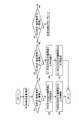
同軸受装置の冷却構造における制御手段の処理例を示す流れ図である。
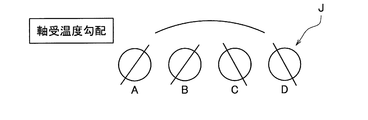
軸受装置における温度勾配例の説明図である。
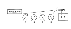
軸受装置における別の温度勾配例の説明図である。
軸受装置におけるさらに別の温度勾配例の説明図である。
軸受装置の冷却構造における圧縮エア無しの場合の軸受温度と軸受の位置との関係を示すシミュレーション例である。
軸受装置の冷却構造における圧縮エア有りの場合の軸受温度と軸受の位置との関係を示すシミュレーション例である。
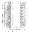
図1の実施形態に係る軸受装置の冷却構造を具体化して適用した工作機械の主軸装置における軸受装置部分の断面図である。
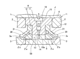
同軸受装置の中央2列の転がり軸受における冷却構造の部分拡大断面図である。
同軸受装置の間座部分の横断面図である。
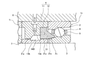
同軸受装置の端部の転がり軸受における冷却構造の部分拡大断面図である。
この発明の第2の実施形態に係る軸受装置の冷却構造の部分断面図である。
同軸受装置の冷却構造の部分拡大断面図である。
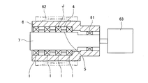
前記各実施形態に係る軸受装置の冷却構造を適用する工作機械の主軸装置の一例を示す概略断面図である。
前記各実施形態に係る軸受装置の冷却構造を適用する工作機械の主軸装置の他の例を示す概略断面図である。
この発明の第1の実施形態を図1ないし図8と共に説明する。図1に示すように、この軸受装置Jの冷却構造は、軸方向に3列以上(図示の例では4列)に並ぶ転がり軸受1の配列における隣合う転がり軸受1,1の外輪2,2間および内輪3,3間に外輪間座4および内輪間座5がそれぞれ介在する。外輪2および外輪間座4がハウジング6の内周に設置され、内輪3および内輪間座5が回転軸である主軸7の外周に嵌合する。
前記外輪間座4に、対向する内輪間座5へ圧縮エアを吐出するエアノズル15が設けられ、これらエアノズル15のそれぞれから吐出される圧縮エアを調整するバルブ51と、これらバルブ51を制御する制御手段52と、前記3列以上の転がり軸受1の温度を計測する複数の温度計測手段53,54とが設けられている。
各エアノズル15は、圧縮エア導入経路45および分岐エア供給経路56を介して、圧縮エアを吐出するエア供給装置57に接続されている。各バルブ51は、電磁開閉弁等の電磁弁からなり、前記制御手段52が出力する制御信号に応答して開閉可能である。なお、バルブ51は、これらをまとめて、流路を切り替える一つまたは複数の切り替え弁としても良い。前記温度計測手段53,54はサーミスタまたは熱電対からなり、個々の転がり軸受1の内輪3および外輪2にそれぞれ接して、主軸7およびハウジング6に設置されている。これら温度計測手段53,54は、前記制御手段52に接続される。主軸7に設置された温度計測手段53の信号線(図示せず)は、スリップリング(図示せず)等を介して主軸端で静止側に取り出されるか、または信号線の代わりに無線が用いられる。
前記制御手段52は、前記複数の温度計測手段53,54で計測された転がり軸受1の温度の計測値、例えば内輪温度と外輪温度との差を用い、定められた規則に従って選んだエアノズル15から圧縮エアが吐出されるように前記バルブ51を制御する。前記制御手段52は、マイクロコンピュータ等の電子回路またはリレー回路等で構成される。前記定められた規則は、任意に設計された内容で良いが、例えば、温度が最も高い転がり軸受1に隣合う内輪間座5に対向するエアノズル15から圧縮エアが吐出されるように前記バルブ51を制御する。図2のフローチャートは、その具体例を示し、後に説明する。
前記外輪間座4のうちのいずれか、具体的には配列の中央の外輪間座4とこれに対応する内輪間座5との間に、エアノズル15から吐出された圧縮エアを当該外輪間座4に隣合う両側の転がり軸受1,1に向けて排出する両側排気経路58を有する。他のいずれか、具体的には両端の外輪間座4とこれに対応する前記内輪間座5との間に、エアノズル15から吐出された圧縮エアを当該外輪間座4に隣合う片側の転がり軸受1に向けて排出する片側排気経路59を有する。また、前記エアノズル15を有する外輪間座4は、エアおよび潤滑油を含む潤滑用流体を、隣接する転がり軸受1へ供給する潤滑用流体吐出手段30を有する。これら両側排気経路58、片側排気経路59、および潤滑用流体吐出手段30は、後に図6,図8等と共に具体的に説明する。
この構成によると、制御手段52は、各部の転がり軸受1の温度計測手段53,54で計測された温度計測値を用い、定められたエアノズル15から圧縮エアが吐出されるようにバルブ51を制御する。そのため、運転条件が種々変化しても、常に、軸受温度が高い箇所を重点的に冷却することができて、限られた圧縮エアを効率良く使用することができる。
制御手段52の具体的処理例を図2と共に説明する。各転がり軸受1の内輪と外輪の温度を温度測定手段53,54で測定し(ステップS1)、何列目の転がり軸受1の温度が一番高いかを判定する(ステップS2,S5,S8,…)。具体的には、まずN列目(Nは自然数)の軸受温度Tが一番高いか否かを判定する(ステップS2)。軸受温度Tは、この例では内輪温度と外輪温度との差とする。内輪温度のみであっても運転に影響する軸受温度の判定は可能であるが、前記差を用いることで、正確な判定を行うことができる。N列目の軸受温度Tが一番高い場合は、N列目の対応する外輪間座4のエアノズル15にバルブ51を切り替え(ステップS3)、N列目の対応する外輪間座4のエアノズル15から圧縮エアを吐出させる(ステップS4)。
ステップS2でN列目の軸受温度Tが一番高いという条件が非充足の場合は、N+1列目の軸受温度T1が一番高いか否かを判定し(ステップS5)、一番高い場合は、N+1列目の対応する外輪間座4のエアノズル15にバルブ51を切り替え(ステップS6)、N列目の対応する外輪間座4のエアノズル15から圧縮エアを吐出させる(ステップS7)。
N列目およびN+1列目の軸受温度T,T1のいずれもが一番高くない場合は、N+2列目の軸受温度T2が一番高いか否かを判定し(ステップS8)、軸受温度が一番高いという条件が充足するまで判定を続け、条件が充足した列についてバルブの切り替えおよび圧縮エアの吐出を行うと、ステップ1へ戻る。なお、列の一端であるN+n列目まで判定を行って軸受温度Tnが一番高いという条件が非充足の場合は、列の他端である1列目に戻って判定を続ける。
このように、常に、温度が最も高い転がり軸受1の近傍の内輪間座5へ圧縮エアを吐出させるようにすると、簡単な制御で効率的に圧縮エアを使用して各転がり軸受1を冷却することができる。
また、外輪間座に隣合う両側の転がり軸受へエアノズルから吐出された圧縮エアと潤滑用流体が同一方向に流れる場合、圧縮エアの両側排気経路58によって、潤滑用流体は圧縮エアに助長され、転がり軸受1内の潤滑用流体の貫通性と排気性が良くなり、潤滑信頼性が向上する(図1の中央の外輪間座参照)。一方、外輪間座に隣合う片側の転がり軸受への圧縮エアと同転がり軸受への他の外輪間座からの潤滑用流体が対向する場合、潤滑用流体は圧縮エアと混流し、転がり軸受内を貫通しづらくなり、排気性も落ちるため、潤滑信頼性が低下する。本実施形態の場合、片側排気経路59を有することで、混流を回避でき、潤滑信頼性を確保することができる。
図3A,3Bは、冷却を行わない場合の、4列構成の軸受装置Jで生じる転がり軸受1間の温度勾配の各種の例を示す。同図の符号A~Dは、転がり軸受1の列を示す。一般的には、図3Aのように、中央2列B,Cの温軸受度が相対的に高く、両端の列A,Dの軸受温度は相対的に低くなる。モータ63,63A(後に図11,図12に示す)の影響が大きい場合は、図3Bのように、モータ63,63A側の列C,Dの軸受温度が相対的に高くなる。上記実施形態の軸受装置の冷却構造を採用すると、図3Cのように列A~Dの軸受温度を同程度とすることができる。
図4Aは、主軸後端にビルトインモータ63Aが設けられた軸受装置Jにおける、圧縮エアの供給無しの場合の軸受温度(内輪と外輪の温度差)と軸受の位置との関係を示すシミュレーション例である。同図のように、圧縮エアの供給無しの場合は、モータ側の列のC,Dの軸受温度が高温になる。
図1の実施形態の冷却構造等を適用し、C列,D列間に圧縮エアを供給した場合は、図4Bのように、列A~Dの軸受温度はある程度均一化される。
図1の実施形態の冷却構造等を適用し、C列,D列間に圧縮エアを供給した場合は、図4Bのように、列A~Dの軸受温度はある程度均一化される。
次に、図1に示す軸受装置の冷却構造の具体的内容につき、図5以降と共に説明する。
この例の軸受装置の冷却構造は、工作機械の主軸装置におけるフロント側の軸受装置に適用されている。ただし、工作機械の主軸装置だけに限定されるものではない。
この例の軸受装置の冷却構造は、工作機械の主軸装置におけるフロント側の軸受装置に適用されている。ただし、工作機械の主軸装置だけに限定されるものではない。
図5は、図の左側が主軸のフロント側、右側がリア側である。同図に示すように、軸受装置Jは、軸方向に並ぶ3つ以上、図示の例では4つの転がり軸受1を備え、隣合う転がり軸受1,1の外輪2,2間および内輪3,3間に、外輪間座4および内輪間座5がそれぞれ介在している。なお、中央2列の転がり軸受1については、添字「I」を、端部の転がり軸受1については添字「O」を付しているが、特に区別を要しない場合は、単に「転がり軸受1」と称す。外輪2および外輪間座4がハウジング6に設置され、内輪3および内輪間座5が主軸7に嵌合している。転がり軸受1はアンギュラ玉軸受であり、内輪3と外輪2の軌道面間に複数の転動体8が介在している。各転動体8は、保持器9により円周方向に等間隔で保持される。中央2つの転がり軸受1I,1Iは背面組合せで配置されており、両端の二つの転がり軸受1O,1Oのそれぞれは、その隣の転がり軸受1Iと同じ向きに配置されている。外輪間座4と内輪間座5とは幅寸法に差が設けられ、これにより各転がり軸受1の初期予圧が設定されて使用される。
外輪2および外輪間座4は、例えばハウジング6に対してすきま嵌めとされ、ハウジング6の段部6aと端面蓋40とにより軸方向の位置決めがされる。また、転がり軸受1の内輪3および内輪間座5は、例えば主軸7に対して締まり嵌めとされ、両側の位置決め間座41,42により軸方向の位置決めがされる。なお、図の左側の位置決め間座42は、主軸7に螺着されたナット43により固定される。各転がり軸受1は内輪回転となる。
冷却構造について説明する。
図5の中央2列の転がり軸受1I,1I間の部分拡大図を図6に示す。外輪間座4は、外輪間座本体11と、この外輪間座本体11とは別部材からなるリング状の鍔部12,12とを有する。鍔部12は、後述の潤滑用流体吐出手段30を構成する。外輪間座本体11は断面略T字形状に形成され、この外輪間座本体11の軸方向両側に鍔部12,12が対称配置で固定されている。外輪間座本体11の内径寸法は、鍔部12,12の内径寸法よりも大きい。これにより、外輪間座4の内周面に、外輪間座本体11の内周面と、この内周面に続く鍔部12,12の側面とで構成される凹み部13が形成されている。この凹み部13は、断面長方形の環状溝である。前記凹み部13によって、外輪2と内輪3との間に環状空間14が構成されている。外輪間座4の凹み部13以外の内周面、すなわち鍔部12,12の内周面と、内輪間座5の外周面とは、微小な径方向すきまδaを介して対向している。これにより、前記凹み部13と内輪間座5の外周面との間に、他よりも径方向幅の広い環状空間14が形成されている。前記環状空間14とその両側の前記径方向すきまδaとで、両側排気経路58が構成される。
図5の中央2列の転がり軸受1I,1I間の部分拡大図を図6に示す。外輪間座4は、外輪間座本体11と、この外輪間座本体11とは別部材からなるリング状の鍔部12,12とを有する。鍔部12は、後述の潤滑用流体吐出手段30を構成する。外輪間座本体11は断面略T字形状に形成され、この外輪間座本体11の軸方向両側に鍔部12,12が対称配置で固定されている。外輪間座本体11の内径寸法は、鍔部12,12の内径寸法よりも大きい。これにより、外輪間座4の内周面に、外輪間座本体11の内周面と、この内周面に続く鍔部12,12の側面とで構成される凹み部13が形成されている。この凹み部13は、断面長方形の環状溝である。前記凹み部13によって、外輪2と内輪3との間に環状空間14が構成されている。外輪間座4の凹み部13以外の内周面、すなわち鍔部12,12の内周面と、内輪間座5の外周面とは、微小な径方向すきまδaを介して対向している。これにより、前記凹み部13と内輪間座5の外周面との間に、他よりも径方向幅の広い環状空間14が形成されている。前記環状空間14とその両側の前記径方向すきまδaとで、両側排気経路58が構成される。
前記外輪間座本体11には、内輪間座5の外周面に向けて冷却用の圧縮エアAを吐出するエアノズル15が設けられている。エアノズル15の出口15aは、外輪間座4の内周面の前記凹み部13に開口している。この例では、複数個(例えば3個)のエアノズル15が、円周方向に等間隔で配置されている(図7参照)。
図7に示すように、各エアノズル15は、内輪間座5の回転方向の前方へ傾斜させてある。つまり、外輪間座4の軸心に垂直な断面における任意の半径方向の直線Lから、この直線Lと直交する方向にオフセットした位置にある。エアノズル15をオフセットさせる理由は、圧縮エアAを内輪間座5の回転方向に旋回流として作用させて、冷却効果を向上させるためである。なお、図5、図6では、外輪間座4を、エアノズル15の中心線を通る断面で表示している。
外輪間座本体11の外周面には、軸受外部から各エアノズル15に圧縮エアAを導入するための導入溝16が形成されている。この導入溝16は、外輪間座4の外周面における軸方向中間部に設けられ、各エアノズル15に連通する円弧状に形成されている。導入溝16は、外輪間座本体11の外周面において、後述のエアオイル供給経路(図示せず)が設けられる円周方向位置を除く円周方向の大部分を示す角度範囲αにわたって設けられている。図5のように、ハウジング6に圧縮エア導入経路45が設けられ、この圧縮エア導入経路45に分岐経路56を介して導入溝16が連通するように構成されている。ハウジング5の外部には、圧縮エア導入孔45に圧縮エアAを供給するエア供給装置57(図1)が設けられている。
図5の右側の端部の転がり軸受1Oおよびその隣の間座の拡大図を図8に示す。図5の左側の端部の転がり軸受1Oおよびその隣の間座については、左右対称である点を除いて図8と同様であるため、説明を省略する。また、端部の転がり軸受1Oおよびその隣の間座は、特に説明する事項を除き、中央2列の転がり軸受1I,1Iおよびその間の間座と同じである。
図8において、端部の転がり軸受1Oの外輪間座4は、前記潤滑用流体供給手段30の鍔部12が、主な冷却目的となる端部の転がり軸受1Oの存在する一方だけに設けられている。外輪間座4の内周面における前記鍔部12と反対側の部分は、鍔部12と同様に外輪間座5の外周面に近接する小径部2aとなる。この小径部2aの側面と、鍔部12の側面と、外輪間座4の幅方向中央部分の内周面とで、環状の凹み部13Aが形成され、この凹み部13Aにより外輪間座4の内周面と外輪間座5の外周面との間の環状空間14Aが構成される。前記小径部2aの環状空間14A側の側面は、内径側が間座幅方向の端部に近づく傾斜面となっている。前記環状空間14Aとその片側の径方向すきまδaとで、片側排気経路59が構成される。
前記環状空間14Aは、エアノズル15の中心軸O15に対する、冷却の主目的となる端部の転がり軸受1O側の部分14A1が、中央の転がり軸受1I側の部分14A2よりも大きな容積を持つように、軸方向に非対称形状に形成されている。具体的には、前記環状空間14Aの前記部分14A1の軸方向長さが、前記部分14A2の軸方向長さよりも長くなっている。前記環状空間14Aの前記両部分14A1,14A2の容積の割合は、例えば6:4、7:3等、適宜に設計され、小さい方の部分14A2は、エアノズル15の開口縁から中心軸O15までの範囲としても良いが、中心軸O15~転がり軸受1I側方向に外輪間座幅の1/5までの範囲が好ましく、より好ましくは中心軸O15~転がり軸受1I側方向に外輪間座幅の1/10までの範囲である。
潤滑構造について説明する。
図5に示すように、各外輪間座4は、潤滑用流体吐出手段30を構成する手段として、前記鍔部12(図6、図8)を有する。各鍔部12は、軸受内に突出して内輪3の外周面との間でエアオイル通過用の環状すきまδbを介して対向する。鍔部12は、内輪3の外周面に被さるように軸受内に進入して配置される。また、鍔部12の先端部は、保持器9の内周面よりも半径方向の内方に配置されている。
図5に示すように、各外輪間座4は、潤滑用流体吐出手段30を構成する手段として、前記鍔部12(図6、図8)を有する。各鍔部12は、軸受内に突出して内輪3の外周面との間でエアオイル通過用の環状すきまδbを介して対向する。鍔部12は、内輪3の外周面に被さるように軸受内に進入して配置される。また、鍔部12の先端部は、保持器9の内周面よりも半径方向の内方に配置されている。
図6に示す外輪間座4に2つ設けられる鍔部12、および図8に示す外輪間座4に1つ設けられる鍔部12のいずれも、この鍔部12と内輪3の外周面間の前記環状すきまδbに開口して潤滑用流体となる例えばエアオイルを供給する潤滑用ノズル31が設けられている。この潤滑用ノズル31は、軸受側に向かうに従い内径側に至るように傾斜し、鍔部12における内輪3と対向する内周面部分に出口が開口している。潤滑用ノズル31には、ハウジング6および外輪間座本体11に設けられた潤滑用流体供給経路(図示せず)を通ってエアオイルが供給される。内輪3の外周面における潤滑用ノズル31の延長線上の箇所には、環状凹み部3aが設けられている。
鍔部12の潤滑用ノズル31から吐出されたエアオイルの油が前記環状凹み部3aに溜り、この油が、内輪3の回転に伴う遠心力により、傾斜面である内輪3の外周面に沿って軸受中心側へと導かれる。
鍔部12の潤滑用ノズル31から吐出されたエアオイルの油が前記環状凹み部3aに溜り、この油が、内輪3の回転に伴う遠心力により、傾斜面である内輪3の外周面に沿って軸受中心側へと導かれる。
排気構造について説明する。
図5に示すように、この軸受装置Jには、冷却用の圧縮エアおよび潤滑用の潤滑用流体であるエアオイルを排気する排気経路46が設けられている。排気経路46は、外輪間座本体11における円周方向の一部に設けられた排気溝47と、ハウジング6に設けられ前記排気溝47に連通する径方向排気孔48および軸方向排気孔49とを有する。前記外輪間座本体11の排気溝47は、潤滑用流体供給経路が設けられる位置とは対角の円周方向位置にわたって形成されている。
図5に示すように、この軸受装置Jには、冷却用の圧縮エアおよび潤滑用の潤滑用流体であるエアオイルを排気する排気経路46が設けられている。排気経路46は、外輪間座本体11における円周方向の一部に設けられた排気溝47と、ハウジング6に設けられ前記排気溝47に連通する径方向排気孔48および軸方向排気孔49とを有する。前記外輪間座本体11の排気溝47は、潤滑用流体供給経路が設けられる位置とは対角の円周方向位置にわたって形成されている。
上記構成からなる軸受装置の冷却構造の作用について説明する。
この軸受装置の冷却構造は、図5に示すように、4列の転がり軸受2からなり、中央2つの転がり軸受1I,1Iについては、1つのエアノズル15から圧縮エアが分岐して吐出されるが、両端の転がり軸受1O,1Oについては、個別にエアノズル15,15から圧縮エアが吐出される。そのため、各転がり軸受1の冷却機能を、これら転がり軸受1の配置場所に応じて調整することができる。また、個々の転がり軸受1の冷却について、次のように効率良く冷却することができる。
この軸受装置の冷却構造は、図5に示すように、4列の転がり軸受2からなり、中央2つの転がり軸受1I,1Iについては、1つのエアノズル15から圧縮エアが分岐して吐出されるが、両端の転がり軸受1O,1Oについては、個別にエアノズル15,15から圧縮エアが吐出される。そのため、各転がり軸受1の冷却機能を、これら転がり軸受1の配置場所に応じて調整することができる。また、個々の転がり軸受1の冷却について、次のように効率良く冷却することができる。
図6および図8に示す各外輪間座4のエアノズル15より、冷却用の圧縮エアAが内輪間座5の外周面に向けて吹き付けられる。このとき、圧縮エアAが狭いエアノズル15内から広い環状空間14,14Aに吐出されることで、圧縮エアAが断熱膨張する。エアノズル15内における圧縮エアの体積をV1、温度をT1とし、環状空間14,14Aでの圧縮エアの体積をV2、温度をT2とした場合、気体の状態方程式、熱力学の第1法則より、V1<V2、T1>T2となる。すなわち、環状空間14,14Aでは、圧縮エアAの温度が下がると共に、体積が増加する。体積が増加することで、圧縮エアAの流速が増大する。このように、低温で高速の圧縮エアAを内輪間座5に吹き付けることで、内輪間座5を効率良く冷却する。
また、エアノズル15が内輪間座5の回転方向の前方へ傾斜しているため、エアノズル15から吐出された圧縮エアAは、内輪間座5の外周面に沿って旋回しながら軸方向に流れて、前記排気経路46を通って軸受外部へ排出される。圧縮エアAが旋回するため、軸方向にまっすぐ流れる場合と比べて、圧縮エアAが内輪間座5の外周面と接している時間が長く、内輪間座5をより一層効率良く冷却することができる。
このように、内輪間座5が効率良く冷却されることで、この内輪間座5を介して転がり軸受1の内輪3および主軸7を効果的に冷却することができる。この冷却構造は、外輪間座4の内周面に環状の凹み部13,13Aを設け、かつエアノズル15を傾斜させるという構造的な工夫を施すだけで冷却効率を向上させることができるため、圧縮エアAを供給するエア供給装置の出力を大きくしなくてもよく、消費電力を抑えることができる。
加えて、外輪間座4の内周面に凹み部13,13Aが設けられていると、次のような効果もある。すなわち、凹み部13,13Aと内輪間座5の間の環状空間14,14Aに吐出された圧縮エアAは、外輪間座4と内輪間座5の間の径方向すきまδaを通って軸受外部へ排出される。その際、少なくとも一部の圧縮エアAは軸受内へ流入する。環状空間14,14Aよりも径方向すきまδaが狭まっているため、径方向すきまδaを流れる圧縮エアAの周方向の各部での流速が均一化され、軸受内に流入する圧縮エアAの流速が均一になる。それにより、圧縮エアAと回転中の転動体9との衝突音を小さくすることができる。
次に、一方の転がり軸受1への重点的な圧縮エアの供給およびその反対側の転がり軸受1における潤滑用流体と圧縮エアとの混流の防止につき説明する。図1に、圧縮エアの流れを外形線太さの矢印で、潤滑用流体の流れを太線の矢印で示すように、端部の転がり軸受1Oに隣接する外輪間座4のエアノズル15から吐出された圧縮エアは、外輪間座4と内輪間座5との間の隙間を通って、その隣の中央側の転がり軸受1Iに内に進入し、潤滑用流体の流れに混流する。
しかし、この実施形態では、前述のように、端部の転がり軸受1Oに隣接する外輪間座4の環状空間14Aは、エアノズル15の中心軸O15に対する端部の転がり軸受1O側の部分14A1が、中央の転がり軸受1I側の部分14A2よりも大きな容積を持つように、軸方向に非対称形状に形成されている。
すなわち、前記環状空間14Aは、エアノズル15の中心軸O15に対し、潤滑用流体の供給側(潤滑用流体吐出手段が設けられた側)の部分14A1が非供給側(潤滑用流体吐出手段が設けられていない側)の部分14A2よりも大きな容積を持つ。前記環状空間14A内に吐出された圧縮エアは、容積の大きい空間部分14A1側へ流れやすいため、前記潤滑用流体の供給側となる端部の転がり軸受1Oへ流れやすい。そのため、この転がり軸受1Oを効果的に冷却することができる。また反対側の転がり軸受1Iへの圧縮エアの流入量が減るため、反対側の転がり軸受1I内での、他の外輪間座4から供給された潤滑用流体と圧縮エアとの混流が緩和される。
すなわち、前記環状空間14Aは、エアノズル15の中心軸O15に対し、潤滑用流体の供給側(潤滑用流体吐出手段が設けられた側)の部分14A1が非供給側(潤滑用流体吐出手段が設けられていない側)の部分14A2よりも大きな容積を持つ。前記環状空間14A内に吐出された圧縮エアは、容積の大きい空間部分14A1側へ流れやすいため、前記潤滑用流体の供給側となる端部の転がり軸受1Oへ流れやすい。そのため、この転がり軸受1Oを効果的に冷却することができる。また反対側の転がり軸受1Iへの圧縮エアの流入量が減るため、反対側の転がり軸受1I内での、他の外輪間座4から供給された潤滑用流体と圧縮エアとの混流が緩和される。
図9,10は、この発明の第2の実施形態を示す。この実施形態において、特に説明する事項の他は、図1~図8と共に説明した第1の実施形態と同様である。この実施形態では、端部の転がり軸受1Oに隣接する外輪間座4と内輪間座5との間に形成される環状空間14Bが、前記外輪間座4の内周面に形成された前記凹み部13aと、前記内輪間座5の外周面に形成された前記凹み部13bとで形成されている。
図8の例のように、前記環状空間14Aが、外輪間座4の内周面に形成された凹み部13Aのみで構成される場合は、内輪間座5の形状が単純な凹凸のない形状で良く、製造が簡単である。しかし、外輪間座4の径方向寸法の制限から、環状空間14Aの容積を十分に得ることが難しい場合がある。しかし、図9,10に示す第2の実施形態のように、環状空間14Bが、外輪間座4に形成された凹み部13aと内輪間座5に形成された凹み部13bとで形成されている場合は、環状空間14Bの容積を大きく得て、エアノズル15から吐出される圧縮エアの断熱膨張を十分に行わせ、冷却効果を高めることができる。
図8の例のように、前記環状空間14Aが、外輪間座4の内周面に形成された凹み部13Aのみで構成される場合は、内輪間座5の形状が単純な凹凸のない形状で良く、製造が簡単である。しかし、外輪間座4の径方向寸法の制限から、環状空間14Aの容積を十分に得ることが難しい場合がある。しかし、図9,10に示す第2の実施形態のように、環状空間14Bが、外輪間座4に形成された凹み部13aと内輪間座5に形成された凹み部13bとで形成されている場合は、環状空間14Bの容積を大きく得て、エアノズル15から吐出される圧縮エアの断熱膨張を十分に行わせ、冷却効果を高めることができる。
図11は、前記各実施形態が適用される工作機械の主軸装置の全体の概略を示す断面図である。主軸7は、前記いずれかの実施形態の軸受装置Jでフロント部が支持され、リア部が他の転がり軸受61で支持されている。ハウジング6の外周には、外筒冷却型の液冷装置62が設けられている。主軸7の後端は、ハウジング6の外部の電動モータ63に連結されている。
図12は、前記軸受装置が適用される工作機械の主軸装置の他の例を示し、ビルトインモータ型とされている。ハウジング6内におけるフロント側の軸受装置Jとリア側の軸受61と間に、電動モータ63Aが設けられている。この電動モータ63Aは、ハウジング6の内周に設けられたステータ64と、主軸7の外周に設けられたロータ65とでなるビルトインモータである。
これら図11、図12の各例に示すように、外部モータ型およびビルトインモータ型のいずれの主軸装置においても、この発明の軸受装置の冷却構造を効果的に適用することができる。
これら図11、図12の各例に示すように、外部モータ型およびビルトインモータ型のいずれの主軸装置においても、この発明の軸受装置の冷却構造を効果的に適用することができる。
以上のとおり、図面を参照しながら好適な実施例を説明したが、当業者であれば、本件明細書を見て、自明な範囲内で種々の変更および修正を容易に想定するであろう。したがって、そのような変更および修正は、添付の請求の範囲から定まるこの発明の範囲内のものと解釈される。
1,1O,1I…転がり軸受
2…外輪
3…内輪
4…外輪間座
5…内輪間座
6…ハウジング
7…主軸
8…転動体
11…外輪間座本体
12…鍔部
13,13A,13a,13b…凹み部
14,14A,14B…環状空間
14A1,14A2……環状空間の部分
15…エアノズル
30…潤滑用流体吐出手段
31…潤滑用ノズル
45…圧縮エア導入経路
46…排気経路
51…バルブ
52…制御手段
56…分岐エア供給経路
57…エア供給装置
58…両側排気経路
59…片側排気経路
A…圧縮エア
O15…中心軸
2…外輪
3…内輪
4…外輪間座
5…内輪間座
6…ハウジング
7…主軸
8…転動体
11…外輪間座本体
12…鍔部
13,13A,13a,13b…凹み部
14,14A,14B…環状空間
14A1,14A2……環状空間の部分
15…エアノズル
30…潤滑用流体吐出手段
31…潤滑用ノズル
45…圧縮エア導入経路
46…排気経路
51…バルブ
52…制御手段
56…分岐エア供給経路
57…エア供給装置
58…両側排気経路
59…片側排気経路
A…圧縮エア
O15…中心軸
Claims (5)
- 軸方向に3列以上に並ぶ転がり軸受の配列における隣合う転がり軸受の外輪間および内輪間に外輪間座および内輪間座がそれぞれ介在し、前記外輪および前記外輪間座がハウジングの内周に設置され、前記内輪および前記内輪間座が回転軸の外周に嵌合する軸受装置の冷却構造であって、
いずれか複数の前記外輪間座に、対向する内輪間座へ圧縮エアを吐出するエアノズルと、これらエアノズルのそれぞれから吐出される圧縮エアを調整するバルブと、これらバルブを制御する制御手段と、前記3列以上の転がり軸受の温度を計測する複数の温度計測手段とを有し、
前記制御手段は、前記複数の温度計測手段で計測された温度の計測値を用い、定められた規則に従って選んだエアノズルから圧縮エアが吐出されるように前記バルブを制御する軸受装置の冷却構造。 - 請求項1に記載の軸受装置の冷却構造において、前記制御手段は、前記複数の温度計測手段で計測された温度の計測値を用い、温度が最も高い転がり軸受に隣合う前記内輪間座に対向する前記エアノズルから圧縮エアが吐出されるように前記バルブを制御する軸受装置の冷却構造。
- 請求項1または請求項2に記載の軸受装置の冷却構造において、いずれかの前記外輪間座とこれに対応する前記内輪間座との間に、前記エアノズルから吐出された圧縮エアを当該外輪間座に隣合う両側の転がり軸受に向けて排出する両側排気経路を有し、他のいずれかの前記外輪間座とこれに対応する前記内輪間座との間に、前記エアノズルから吐出された圧縮エアを当該外輪間座に隣合う片側の転がり軸受に向けて排出する片側排気経路を有する軸受装置の冷却構造。
- 請求項3に記載の軸受装置の冷却構造において、前記片側排気経路は、前記外輪間座と内輪間座との間の隙間と、前記外輪間座と内輪間座との間に形成されて前記隙間よりも径方向寸法が大きい環状空間とを有し、前記エアノズルが前記環状空間に開口し、前記環状空間における、前記エアノズルの中心軸に対する一方の部分が、他方の部分よりも大きな容積を持つ軸受装置の冷却構造。
- 請求項1ないし請求項4のいずれか1項に記載の軸受装置の冷却構造において、前記エアノズルを有する前記外輪間座が、エアおよび潤滑油を含む潤滑用流体を隣接する転がり軸受へ供給する潤滑用流体吐出手段を有する軸受装置の冷却構造。
Priority Applications (3)
| Application Number | Priority Date | Filing Date | Title |
|---|---|---|---|
| EP17868539.2A EP3540255B1 (en) | 2016-11-10 | 2017-11-08 | Cooling structure for a bearing device |
| KR1020197015962A KR102465342B1 (ko) | 2016-11-10 | 2017-11-08 | 베어링 장치의 냉각 구조 |
| CN201780069284.1A CN110036215B (zh) | 2016-11-10 | 2017-11-08 | 轴承装置的冷却结构 |
Applications Claiming Priority (2)
| Application Number | Priority Date | Filing Date | Title |
|---|---|---|---|
| JP2016219512A JP6831162B2 (ja) | 2016-11-10 | 2016-11-10 | 軸受装置の冷却構造 |
| JP2016-219512 | 2016-11-10 |
Publications (2)
| Publication Number | Publication Date |
|---|---|
| WO2018088414A1 true WO2018088414A1 (ja) | 2018-05-17 |
| WO2018088414A8 WO2018088414A8 (ja) | 2019-05-31 |
Family
ID=62109578
Family Applications (1)
| Application Number | Title | Priority Date | Filing Date |
|---|---|---|---|
| PCT/JP2017/040200 Ceased WO2018088414A1 (ja) | 2016-11-10 | 2017-11-08 | 軸受装置の冷却構造 |
Country Status (5)
| Country | Link |
|---|---|
| EP (1) | EP3540255B1 (ja) |
| JP (1) | JP6831162B2 (ja) |
| KR (1) | KR102465342B1 (ja) |
| CN (1) | CN110036215B (ja) |
| WO (1) | WO2018088414A1 (ja) |
Cited By (2)
| Publication number | Priority date | Publication date | Assignee | Title |
|---|---|---|---|---|
| CN113070195A (zh) * | 2021-04-01 | 2021-07-06 | 山东金帝精密机械科技股份有限公司 | 一种轴承保持器的浸塑冷却装置 |
| CN113631822A (zh) * | 2019-03-25 | 2021-11-09 | Ntn株式会社 | 轴承装置 |
Families Citing this family (6)
| Publication number | Priority date | Publication date | Assignee | Title |
|---|---|---|---|---|
| JP6967495B2 (ja) * | 2018-09-03 | 2021-11-17 | Ntn株式会社 | 軸受装置 |
| CN112943808B (zh) * | 2021-03-23 | 2022-07-05 | 北新集团建材股份有限公司 | 一种轴承自动润滑系统及其打散机 |
| CN113294431B (zh) * | 2021-04-27 | 2022-08-30 | 洛阳轴承研究所有限公司 | 一种串联组配的推力轴承组 |
| JP7779083B2 (ja) * | 2021-10-28 | 2025-12-03 | 株式会社ジェイテクト | 主軸装置 |
| KR102663414B1 (ko) | 2022-03-23 | 2024-05-08 | 에스케이온 주식회사 | 이차전지 전극시트 압연장치, 이를 이용하여 제조된 양극 전극 및 이차전지 |
| CN119802078A (zh) * | 2024-12-30 | 2025-04-11 | 宁波市镇海金金耐驰轴承有限公司 | 一种用于滚动轴承的加工方法 |
Citations (7)
| Publication number | Priority date | Publication date | Assignee | Title |
|---|---|---|---|---|
| JPH1034494A (ja) * | 1996-07-22 | 1998-02-10 | Okuma Mach Works Ltd | 軸受装置 |
| JP2000161375A (ja) | 1998-11-26 | 2000-06-13 | Matsuura Machinery Corp | 回転主軸冷却構造 |
| JP2004100729A (ja) * | 2002-09-05 | 2004-04-02 | Mitsubishi Heavy Ind Ltd | すべり軸受 |
| JP2008075882A (ja) * | 2007-12-11 | 2008-04-03 | Nsk Ltd | 軸受装置 |
| JP2008106891A (ja) * | 2006-10-27 | 2008-05-08 | Ntn Corp | 転がり軸受の予圧調整方法およびその装置 |
| WO2014046153A1 (ja) * | 2012-09-24 | 2014-03-27 | Ntn株式会社 | 軸受装置の冷却構造 |
| JP2015183738A (ja) | 2014-03-22 | 2015-10-22 | Ntn株式会社 | 軸受装置の冷却構造 |
Family Cites Families (8)
| Publication number | Priority date | Publication date | Assignee | Title |
|---|---|---|---|---|
| EP1579951B1 (de) * | 2004-03-22 | 2008-03-19 | Paul Müller GmbH & Co. KG Unternehmensbeteiligungen | Spindel für eine Werkzeugmaschine mit einem Lagerelement mit einer kapillaren Zuleitung zur Zuführung von Schmierstoff |
| JP4569747B2 (ja) * | 2004-07-07 | 2010-10-27 | 株式会社ジェイテクト | 軸受用潤滑剤供給装置 |
| JP2006118526A (ja) * | 2004-10-19 | 2006-05-11 | Ntn Corp | 転がり軸受の潤滑装置 |
| JP2006194402A (ja) * | 2005-01-17 | 2006-07-27 | Jtekt Corp | 転がり軸受装置 |
| JP5607285B2 (ja) * | 2006-06-23 | 2014-10-15 | 日本精工株式会社 | 軸受装置 |
| JP5419392B2 (ja) * | 2007-08-24 | 2014-02-19 | Ntn株式会社 | 転がり軸受装置 |
| JP2015117820A (ja) * | 2013-11-18 | 2015-06-25 | Ntn株式会社 | 軸受装置の冷却構造 |
| WO2015146569A1 (ja) * | 2014-03-22 | 2015-10-01 | Ntn株式会社 | 軸受装置の冷却構造 |
-
2016
- 2016-11-10 JP JP2016219512A patent/JP6831162B2/ja active Active
-
2017
- 2017-11-08 KR KR1020197015962A patent/KR102465342B1/ko active Active
- 2017-11-08 CN CN201780069284.1A patent/CN110036215B/zh active Active
- 2017-11-08 WO PCT/JP2017/040200 patent/WO2018088414A1/ja not_active Ceased
- 2017-11-08 EP EP17868539.2A patent/EP3540255B1/en active Active
Patent Citations (7)
| Publication number | Priority date | Publication date | Assignee | Title |
|---|---|---|---|---|
| JPH1034494A (ja) * | 1996-07-22 | 1998-02-10 | Okuma Mach Works Ltd | 軸受装置 |
| JP2000161375A (ja) | 1998-11-26 | 2000-06-13 | Matsuura Machinery Corp | 回転主軸冷却構造 |
| JP2004100729A (ja) * | 2002-09-05 | 2004-04-02 | Mitsubishi Heavy Ind Ltd | すべり軸受 |
| JP2008106891A (ja) * | 2006-10-27 | 2008-05-08 | Ntn Corp | 転がり軸受の予圧調整方法およびその装置 |
| JP2008075882A (ja) * | 2007-12-11 | 2008-04-03 | Nsk Ltd | 軸受装置 |
| WO2014046153A1 (ja) * | 2012-09-24 | 2014-03-27 | Ntn株式会社 | 軸受装置の冷却構造 |
| JP2015183738A (ja) | 2014-03-22 | 2015-10-22 | Ntn株式会社 | 軸受装置の冷却構造 |
Non-Patent Citations (1)
| Title |
|---|
| See also references of EP3540255A4 |
Cited By (2)
| Publication number | Priority date | Publication date | Assignee | Title |
|---|---|---|---|---|
| CN113631822A (zh) * | 2019-03-25 | 2021-11-09 | Ntn株式会社 | 轴承装置 |
| CN113070195A (zh) * | 2021-04-01 | 2021-07-06 | 山东金帝精密机械科技股份有限公司 | 一种轴承保持器的浸塑冷却装置 |
Also Published As
| Publication number | Publication date |
|---|---|
| EP3540255A1 (en) | 2019-09-18 |
| JP2018076923A (ja) | 2018-05-17 |
| WO2018088414A8 (ja) | 2019-05-31 |
| CN110036215A (zh) | 2019-07-19 |
| CN110036215B (zh) | 2021-03-09 |
| KR20190076027A (ko) | 2019-07-01 |
| EP3540255B1 (en) | 2021-09-15 |
| EP3540255A4 (en) | 2020-07-08 |
| KR102465342B1 (ko) | 2022-11-08 |
| JP6831162B2 (ja) | 2021-02-17 |
Similar Documents
| Publication | Publication Date | Title |
|---|---|---|
| KR102465342B1 (ko) | 베어링 장치의 냉각 구조 | |
| EP3124812B1 (en) | Cooling structure for bearing device | |
| US8956050B2 (en) | Rolling bearing and rolling bearing assembly | |
| JP6013112B2 (ja) | 軸受装置の冷却構造 | |
| JP2014062616A (ja) | 軸受装置の冷却構造 | |
| WO2015072383A1 (ja) | 軸受装置の冷却構造 | |
| JP6050072B2 (ja) | 軸受装置の冷却構造 | |
| US10001170B2 (en) | Rolling bearing | |
| WO2015128893A1 (ja) | ボールねじ | |
| EP3851692B1 (en) | Bearing device cooling structure, and main spindle device of machine tool | |
| JP6009296B2 (ja) | 軸受装置の冷却構造 | |
| KR102448407B1 (ko) | 베어링 장치의 냉각 구조 | |
| WO2018074375A1 (ja) | 軸受装置の冷却構造 | |
| JP6609003B2 (ja) | 軸受装置の冷却構造 | |
| JP6385089B2 (ja) | 軸受装置の冷却構造 | |
| JP6702320B2 (ja) | 冷却液排出装置、ボールねじ装置 | |
| WO2018181033A1 (ja) | 軸受装置の冷却構造 | |
| EP3696434A1 (en) | Cooling structure for bearing device | |
| WO2018181032A1 (ja) | 軸受装置の冷却構造 | |
| JP7185546B2 (ja) | 軸受装置の冷却構造および工作機械の主軸装置 | |
| JP6983029B2 (ja) | 軸受装置の冷却構造 | |
| JP2008157403A (ja) | 軸受冷却装置 | |
| JP2017031984A (ja) | 転がり軸受 |
Legal Events
| Date | Code | Title | Description |
|---|---|---|---|
| 121 | Ep: the epo has been informed by wipo that ep was designated in this application |
Ref document number: 17868539 Country of ref document: EP Kind code of ref document: A1 |
|
| NENP | Non-entry into the national phase |
Ref country code: DE |
|
| ENP | Entry into the national phase |
Ref document number: 20197015962 Country of ref document: KR Kind code of ref document: A |
|
| ENP | Entry into the national phase |
Ref document number: 2017868539 Country of ref document: EP Effective date: 20190611 |