WO2018092366A1 - 硫化物固体電解質 - Google Patents
硫化物固体電解質 Download PDFInfo
- Publication number
- WO2018092366A1 WO2018092366A1 PCT/JP2017/028791 JP2017028791W WO2018092366A1 WO 2018092366 A1 WO2018092366 A1 WO 2018092366A1 JP 2017028791 W JP2017028791 W JP 2017028791W WO 2018092366 A1 WO2018092366 A1 WO 2018092366A1
- Authority
- WO
- WIPO (PCT)
- Prior art keywords
- solid electrolyte
- sulfide solid
- crystal structure
- peak
- sulfide
- Prior art date
- Legal status (The legal status is an assumption and is not a legal conclusion. Google has not performed a legal analysis and makes no representation as to the accuracy of the status listed.)
- Ceased
Links
Images


Classifications
-
- H—ELECTRICITY
- H01—ELECTRIC ELEMENTS
- H01M—PROCESSES OR MEANS, e.g. BATTERIES, FOR THE DIRECT CONVERSION OF CHEMICAL ENERGY INTO ELECTRICAL ENERGY
- H01M10/00—Secondary cells; Manufacture thereof
- H01M10/05—Accumulators with non-aqueous electrolyte
- H01M10/056—Accumulators with non-aqueous electrolyte characterised by the materials used as electrolytes, e.g. mixed inorganic/organic electrolytes
- H01M10/0561—Accumulators with non-aqueous electrolyte characterised by the materials used as electrolytes, e.g. mixed inorganic/organic electrolytes the electrolyte being constituted of inorganic materials only
- H01M10/0562—Solid materials
-
- C—CHEMISTRY; METALLURGY
- C01—INORGANIC CHEMISTRY
- C01D—COMPOUNDS OF ALKALI METALS, i.e. LITHIUM, SODIUM, POTASSIUM, RUBIDIUM, CAESIUM, OR FRANCIUM
- C01D15/00—Lithium compounds
-
- C—CHEMISTRY; METALLURGY
- C03—GLASS; MINERAL OR SLAG WOOL
- C03C—CHEMICAL COMPOSITION OF GLASSES, GLAZES OR VITREOUS ENAMELS; SURFACE TREATMENT OF GLASS; SURFACE TREATMENT OF FIBRES OR FILAMENTS MADE FROM GLASS, MINERALS OR SLAGS; JOINING GLASS TO GLASS OR OTHER MATERIALS
- C03C3/00—Glass compositions
- C03C3/12—Silica-free oxide glass compositions
- C03C3/23—Silica-free oxide glass compositions containing halogen and at least one oxide, e.g. oxide of boron
-
- C—CHEMISTRY; METALLURGY
- C03—GLASS; MINERAL OR SLAG WOOL
- C03C—CHEMICAL COMPOSITION OF GLASSES, GLAZES OR VITREOUS ENAMELS; SURFACE TREATMENT OF GLASS; SURFACE TREATMENT OF FIBRES OR FILAMENTS MADE FROM GLASS, MINERALS OR SLAGS; JOINING GLASS TO GLASS OR OTHER MATERIALS
- C03C4/00—Compositions for glass with special properties
- C03C4/14—Compositions for glass with special properties for electro-conductive glass
-
- H—ELECTRICITY
- H01—ELECTRIC ELEMENTS
- H01B—CABLES; CONDUCTORS; INSULATORS; SELECTION OF MATERIALS FOR THEIR CONDUCTIVE, INSULATING OR DIELECTRIC PROPERTIES
- H01B1/00—Conductors or conductive bodies characterised by the conductive materials; Selection of materials as conductors
- H01B1/06—Conductors or conductive bodies characterised by the conductive materials; Selection of materials as conductors mainly consisting of other non-metallic substances
-
- H—ELECTRICITY
- H01—ELECTRIC ELEMENTS
- H01M—PROCESSES OR MEANS, e.g. BATTERIES, FOR THE DIRECT CONVERSION OF CHEMICAL ENERGY INTO ELECTRICAL ENERGY
- H01M10/00—Secondary cells; Manufacture thereof
- H01M10/05—Accumulators with non-aqueous electrolyte
- H01M10/052—Li-accumulators
-
- H—ELECTRICITY
- H01—ELECTRIC ELEMENTS
- H01M—PROCESSES OR MEANS, e.g. BATTERIES, FOR THE DIRECT CONVERSION OF CHEMICAL ENERGY INTO ELECTRICAL ENERGY
- H01M10/00—Secondary cells; Manufacture thereof
- H01M10/05—Accumulators with non-aqueous electrolyte
- H01M10/052—Li-accumulators
- H01M10/0525—Rocking-chair batteries, i.e. batteries with lithium insertion or intercalation in both electrodes; Lithium-ion batteries
-
- H—ELECTRICITY
- H01—ELECTRIC ELEMENTS
- H01M—PROCESSES OR MEANS, e.g. BATTERIES, FOR THE DIRECT CONVERSION OF CHEMICAL ENERGY INTO ELECTRICAL ENERGY
- H01M4/00—Electrodes
- H01M4/02—Electrodes composed of, or comprising, active material
- H01M4/62—Selection of inactive substances as ingredients for active masses, e.g. binders, fillers
-
- C—CHEMISTRY; METALLURGY
- C01—INORGANIC CHEMISTRY
- C01P—INDEXING SCHEME RELATING TO STRUCTURAL AND PHYSICAL ASPECTS OF SOLID INORGANIC COMPOUNDS
- C01P2002/00—Crystal-structural characteristics
- C01P2002/70—Crystal-structural characteristics defined by measured X-ray, neutron or electron diffraction data
- C01P2002/72—Crystal-structural characteristics defined by measured X-ray, neutron or electron diffraction data by d-values or two theta-values, e.g. as X-ray diagram
-
- C—CHEMISTRY; METALLURGY
- C01—INORGANIC CHEMISTRY
- C01P—INDEXING SCHEME RELATING TO STRUCTURAL AND PHYSICAL ASPECTS OF SOLID INORGANIC COMPOUNDS
- C01P2006/00—Physical properties of inorganic compounds
- C01P2006/80—Compositional purity
-
- H—ELECTRICITY
- H01—ELECTRIC ELEMENTS
- H01M—PROCESSES OR MEANS, e.g. BATTERIES, FOR THE DIRECT CONVERSION OF CHEMICAL ENERGY INTO ELECTRICAL ENERGY
- H01M2300/00—Electrolytes
- H01M2300/0017—Non-aqueous electrolytes
- H01M2300/0065—Solid electrolytes
- H01M2300/0068—Solid electrolytes inorganic
-
- H—ELECTRICITY
- H01—ELECTRIC ELEMENTS
- H01M—PROCESSES OR MEANS, e.g. BATTERIES, FOR THE DIRECT CONVERSION OF CHEMICAL ENERGY INTO ELECTRICAL ENERGY
- H01M2300/00—Electrolytes
- H01M2300/0017—Non-aqueous electrolytes
- H01M2300/0065—Solid electrolytes
- H01M2300/0068—Solid electrolytes inorganic
- H01M2300/008—Halides
-
- H—ELECTRICITY
- H01—ELECTRIC ELEMENTS
- H01M—PROCESSES OR MEANS, e.g. BATTERIES, FOR THE DIRECT CONVERSION OF CHEMICAL ENERGY INTO ELECTRICAL ENERGY
- H01M4/00—Electrodes
- H01M4/02—Electrodes composed of, or comprising, active material
- H01M4/13—Electrodes for accumulators with non-aqueous electrolyte, e.g. for lithium-accumulators; Processes of manufacture thereof
-
- Y—GENERAL TAGGING OF NEW TECHNOLOGICAL DEVELOPMENTS; GENERAL TAGGING OF CROSS-SECTIONAL TECHNOLOGIES SPANNING OVER SEVERAL SECTIONS OF THE IPC; TECHNICAL SUBJECTS COVERED BY FORMER USPC CROSS-REFERENCE ART COLLECTIONS [XRACs] AND DIGESTS
- Y02—TECHNOLOGIES OR APPLICATIONS FOR MITIGATION OR ADAPTATION AGAINST CLIMATE CHANGE
- Y02E—REDUCTION OF GREENHOUSE GAS [GHG] EMISSIONS, RELATED TO ENERGY GENERATION, TRANSMISSION OR DISTRIBUTION
- Y02E60/00—Enabling technologies; Technologies with a potential or indirect contribution to GHG emissions mitigation
- Y02E60/10—Energy storage using batteries
Definitions
- the present invention relates to a sulfide solid electrolyte.
- lithium-ion batteries use electrolytes containing flammable organic solvents, so safety devices that prevent temperature rises during short circuits and improvements in structure and materials to prevent short circuits Is required.
- a lithium ion battery that uses a solid electrolyte by changing the electrolyte to a solid electrolyte does not use a flammable organic solvent in the battery, so the safety device can be simplified, and manufacturing costs and productivity can be reduced. It is considered excellent.
- a sulfide solid electrolyte is known as a solid electrolyte used in a lithium ion battery.
- Various crystal structures of sulfide solid electrolytes are known. One of them is an Argyrodite type crystal structure (Patent Documents 1 to 5, Non-Patent Documents 1 to 4).
- Algirodite type crystal structure is a crystal with high stability, and some have high ionic conductivity. However, further improvements in ionic conductivity are desired.
- One of the objects of the present invention is to provide a novel sulfide solid electrolyte having high ionic conductivity.
- an argilodite-type crystal comprising lithium, phosphorus, sulfur and chlorine, having a molar ratio c (Cl / P) of chlorine to phosphorus of greater than 1.0 and 1.9 or less.
- a sulfide solid electrolyte having a structure and having a lattice constant of not less than 9.750 and not more than 9.820 in the argilodite crystal structure.
- the electrode compound material containing the said sulfide solid electrolyte and an active material is provided.
- a lithium ion battery including at least one of the sulfide solid electrolyte and the electrode mixture.
- a novel sulfide solid electrolyte with high ionic conductivity can be provided.
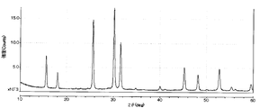
- FIG. 2 is an X-ray diffraction (XRD) pattern of the sulfide solid electrolyte obtained in Example 1.
- FIG. 3 is a solid 31 P-NMR spectrum of the sulfide solid electrolyte obtained in Example 1.
- 4 is an XRD pattern of the intermediate obtained in Example 4.
- 7 is an XRD pattern of a mixed powder obtained in Comparative Example 5.
- the first aspect of the sulfide solid electrolyte of the present invention contains lithium, phosphorus, sulfur and chlorine, and the molar ratio c (Cl / P) of chlorine to phosphorus is greater than 1.0 and 1.9 or less. And it has an argilodite type crystal structure, and the lattice constant of the argilodite type crystal structure is 9.750 ⁇ or more and 9.820 ⁇ or less.
- the molar ratio c (Cl / P) of chlorine to phosphorus is larger than 1.0, and the lattice constant of the aldilodite crystal structure contained in the sulfide solid electrolyte is 9.820 ⁇ or less.
- a small lattice constant of the aldilodite type crystal structure is considered to mean that the amount of chlorine contained in the crystal structure is large.
- various crystalline components and amorphous components are mixed in the sulfide solid electrolyte.
- Some of the chlorine added as a constituent element of the sulfide solid electrolyte forms an aldilodite-type crystal structure, and other chlorine forms a crystal structure and an amorphous component other than the aldilodite-type crystal structure. Moreover, the case where it is contained in the residual raw material is also considered.
- the present inventors have found that by increasing the amount of chlorine contained in the aldilodite-type crystal structure, the lattice constant of the aldilodite-type crystal structure is reduced, and the ionic conductivity of the sulfide solid electrolyte can be improved.
- the lattice constant of the aldilodite crystal structure contained in the sulfide solid electrolyte is 9.8189 or less.
- the lattice constant of the aldilodite type crystal structure contained in the sulfide solid electrolyte is 9.815 ⁇ or less.
- the molar ratio c is usually 1.9 or less, but may be 1.8 or less.
- the lattice constant of the aldilodite type crystal structure is 9.750 to 9.820, preferably 9.79 to 9.820, more preferably 9.79 to 9.815. .
- the measuring method of ICP emission spectrometry is described in an Example.
- the molar ratio of each element can be controlled by adjusting the content of each element in the raw material.
- the lattice constant of the argilodite-type crystal structure is calculated from the XRD pattern obtained by X-ray diffractometry (XRD) by analyzing the entire pattern fitting (WPF) with crystal structure analysis software. Details of the measurement are given in the examples.
- the sulfide solid electrolyte of this embodiment includes an argilodite type crystal structure.
- the diffraction peak is a peak derived from an aldilodite type crystal structure.
- the sulfide solid electrolyte of the present invention may have these peaks.
- the position of the diffraction peak is determined as A ⁇ 0.5 deg or A ⁇ 0.4 deg when the median is A, but is preferably A ⁇ 0.3 deg.
- aldilodite-type crystal structure examples include the crystal structures disclosed in Non-Patent Documents 1 to 3, JP-T 2010-540396, JP-A 2011-096630, and JP-A 2013-2111171. it can.
- the second aspect of the sulfide solid electrolyte of the present invention contains lithium, phosphorus, sulfur and chlorine, and has a molar ratio c (Cl / P) of chlorine to phosphorus of more than 1.0 and 1.9 or less. Has a crystalline structure. Then, in solid 31 P-NMR measurement, each peak has 80.3 to 81.7 ppm, 82.4 to 83.7 ppm, and 84.0 to 85.6 ppm, and the total of all peaks at 78 to 92 ppm The area ratio of the peak at 80.3 to 81.7 ppm relative to the area is 40% or more.
- the molar ratio c (Cl / P) of chlorine to phosphorus and the aldilodite crystal structure are the same as those of the first embodiment described above.
- the sulfide solid electrolyte of this embodiment has a solid 31 P-NMR measurement of 80.3 to 81.7 ppm (hereinafter referred to as the first region) and 82.4 to 83.7 ppm (hereinafter referred to as the second region). And 84.0 to 85.6 ppm (hereinafter referred to as the third region).
- the peak in the first region is referred to as a first peak (P 1 )
- the peak in the second region is referred to as a second peak (P 2 )
- the peak in the third region is referred to as a third peak (P 3 ).
- a peak in a region means that there is a peak having a peak top in the region, or that there is a peak in this region during separation by the non-linear least square method.
- the ratio (S P1 ⁇ 100 / S all ) of the area (S P1 ) of the first peak to the total area (S all ) of all peaks at 78 to 92 ppm is 40% or more. It is presumed that a high area ratio of the first peak indicates that a large amount of chlorine is incorporated into the argilodite type crystal structure. As a result, the ionic conductivity of the solid electrolyte is increased.
- the sulfide solid electrolyte of this embodiment preferably has an area ratio of the first peak of 45% or more when the molar ratio c is 1.2 or more.
- the area ratio of the first peak is 50% or more.
- the molar ratio c is usually 1.9 or less, but may be 1.8 or less.
- the area ratio of the first peak is usually 65% or less.
- Non-patent Document 4 the azirodite type crystal structure (Li 6 PS 5 Cl) in which the halogen is chlorine has two types of free element sites having different occupancy rates of chlorine and sulfur.
- the free element means sulfur or halogen surrounded by Li in the argilodite type crystal structure.
- the solid 31 P-NMR spectrum has resonance lines of a plurality of phosphorus having different chemical shifts. It has been reported that they are observed in an overlapping manner (Non-Patent Document 1).
- the present inventors examined solid 31 P-NMR spectra of azirodite crystals having different ratios of free Cl and free S. As a result, it was found that the NMR signal observed in the region of 78 to 92 ppm can be separated into three types of PS 4 3- structure peaks having different distribution states of surrounding free S and free Cl. Moreover, when the area ratio of the peak (the said 1st peak) of the highest magnetic field side among three types of peaks is high, it discovered that the ionic conductivity of a solid electrolyte was high. From this fact, the first peak is presumed to be a peak of PS 4 3- structure in which all of the surrounding free elements are Cl.
- the ratio of the area of the peaks at 84.0 ⁇ 85.6ppm to the total area (S all) (P 3) (S P3) (S P3 ⁇ 100 / S all) is not more than 30% preferable. Within this range, it is considered that the structure has a small number of free S surrounded by Li adjacent to the PS 4 3- structure.
- the area ratio of the third peak is 25% or less.
- the area ratio of the third peak is 20% or less.
- the area ratio of the third peak is usually 15% or more.
- the total area ratio (S P2 ⁇ 100 / S all ) of the area of the peak in 82.4 ⁇ 83.7ppm for (S all) (P 2) (S P2) is 20% to 35% Is preferred. If it is within this range, it is presumed that free Cl close to the PS 4 3- structure is larger than the number of free S, so that a high ion conduction phase is considered to be obtained.
- the area ratio of the second peak is more preferably 21% or more and 32% or less, and more preferably 22% or more and 30% or less.
- the sulfide solid electrolyte of the present invention only needs to have the configuration of the first aspect or the second aspect described above. Moreover, you may have all the structures prescribed
- the sulfide solid electrolytes of the first and second aspects of the present invention are collectively referred to as “the sulfide solid electrolyte of the present invention”.
- the sulfide solid electrolyte of the present invention has a molar ratio a (Li / P) of lithium to phosphorus, a molar ratio b (S / P) of sulfur to phosphorus, and a molar ratio c (Cl / P) of chlorine to phosphorus.
- a molar ratio a (Li / P) of lithium to phosphorus a molar ratio b (S / P) of sulfur to phosphorus
- a molar ratio c (Cl / P) of chlorine to phosphorus it is preferable that the following formulas (A) to (C) are satisfied. 5.0 ⁇ a ⁇ 6.5 (A) 6.1 ⁇ a + c ⁇ 7.5 (B) 0.5 ⁇ ab ⁇ 1.5 (C) (In the formula, b> 0 and c> 1.0 are satisfied.)
- an aldilodite crystal structure is easily formed.
- the formula (A) preferably satisfies 5.1 ⁇ a ⁇ 6.4, and more preferably satisfies 5.2 ⁇ a ⁇ 6.3.
- 6.2 ⁇ a + c ⁇ 7.4 is preferable, and 6.3 ⁇ a + c ⁇ 7.3 is more preferable.
- 0.6 ⁇ ab ⁇ 1.3 is preferable, and 0.7 ⁇ ab ⁇ 1.3 is more preferable.
- elements such as Si, Ge, Sn, Pb, B, Al, Ga, As, Sb, and Bi may be included in addition to the lithium, phosphorus, sulfur, and chlorine.
- the sulfide solid electrolyte contains one or more elements M selected from the group consisting of Si, Ge, Sn, Pb, B, Al, Ga, As, Sb, and Bi
- the molar ratio of each element is the molar ratio with respect to the total of the element M and phosphorus.
- the molar ratio a (Li / P) of lithium to phosphorus is Li / (P + M).
- a halogen element other than chlorine and a chalcogen element oxygen (O), selenium (Se), tellurium (Te), etc.
- O oxygen
- Se selenium
- Te tellurium
- the sulfide solid electrolyte of the present invention preferably satisfies, for example, a composition represented by the following formula (1).
- Li a PS b Cl c (1) (In the formula (1), a to c satisfy the following formulas (A) to (C).) 5.0 ⁇ a ⁇ 6.5 (A) 6.1 ⁇ a + c ⁇ 7.5 (B) 0.5 ⁇ ab ⁇ 1.5 (C) (In the formula, b> 0 and c> 1.0 are satisfied.)
- the formula (A) preferably satisfies 5.1 ⁇ a ⁇ 6.4, and more preferably satisfies 5.2 ⁇ a ⁇ 6.3.
- 6.2 ⁇ a + c ⁇ 7.4 is preferable, and 6.3 ⁇ a + c ⁇ 7.3 is more preferable.
- 0.6 ⁇ ab ⁇ 1.3 is preferable, and 0.7 ⁇ ab ⁇ 1.3 is more preferable.
- the above-mentioned molar ratios and compositions of the elements are not the molar ratios and compositions of the input materials used in the production, but the products in the sulfide solid electrolyte.
- the molar ratio of each element can be controlled by adjusting the content of each element in the raw material, for example.
- the above formula (2) represents that the amount of LiCl is relatively small as compared with the aldilodite type crystal structure.
- Equation (2) is 0 ⁇ more preferably I A / I B ⁇ 0.04, even more preferably from 0 ⁇ I A / I B ⁇ 0.03.
- Li 3 PS 4 crystal structure Since the crystal structure specified by I C (hereinafter referred to as Li 3 PS 4 crystal structure) has low ionic conductivity, the ionic conductivity of the solid electrolyte is lowered.
- the above formula (3) represents that the amount of the Li 3 PS 4 crystal structure is relatively small as compared with the aldilodite crystal structure.
- 0 ⁇ I E / ID ⁇ 0.05 is more preferable, and 0 ⁇ I E / ID ⁇ 0.03 is further preferable.
- the present invention is not limited to these.
- the sulfide solid electrolyte of the present invention is, for example, a process comprising a step of producing an intermediate by reacting a mixture of raw materials described later by applying mechanical stress, and a step of crystallizing the intermediate by heat treatment It can be produced by a method.
- the raw material to be used is a combination of two or more compounds or simple substances containing the elements contained in the sulfide solid electrolyte to be produced, that is, lithium, phosphorus, sulfur and chlorine as a whole.
- Examples of the raw material containing lithium include lithium compounds such as lithium sulfide (Li 2 S), lithium oxide (Li 2 O), and lithium carbonate (Li 2 CO 3 ), and lithium metal alone. Among these, lithium compounds are preferable, and lithium sulfide is more preferable. Although the said lithium sulfide can be used without a restriction
- Lithium can be synthesized (Japanese Patent Laid-Open No. 2010-163356). In addition, lithium hydroxide and hydrogen sulfide are reacted at 10 ° C. to 100 ° C. in an aqueous solvent to produce lithium hydrosulfide, and then this reaction solution is dehydrosulfurized to synthesize lithium sulfide (special feature). No. 2011-84438).
- Examples of the raw material containing phosphorus include phosphorus sulfide such as diphosphorus trisulfide (P 2 S 3 ) and diphosphorus pentasulfide (P 2 S 5 ), phosphorus compounds such as sodium phosphate (Na 3 PO 4 ), and Examples include phosphorus alone. Among these, phosphorus sulfide is preferable and diphosphorus pentasulfide (P 2 S 5 ) is more preferable. Phosphorus compounds such as diphosphorus pentasulfide (P 2 S 5 ) and simple phosphorus can be used without particular limitation as long as they are industrially produced and sold.
- a chlorine compound represented by the following formula (4) is preferable.
- M is sodium (Na), lithium (Li), boron (B), aluminum (Al), silicon (Si), phosphorus (P), sulfur (S), germanium (Ge), arsenic (As), selenium (Se), tin (Sn), antimony (Sb), tellurium (Te), lead (Pb), bismuth (Bi), or a combination of these elements with oxygen and sulfur Lithium (Li) or phosphorus (P) is preferable, and lithium (Li) is more preferable.
- l is an integer of 1 or 2
- m is an integer of 1 to 10.
- Chlorine compounds specifically, NaCl, LiCl, BCl 3, AlCl 3, SiCl 4, SiCl 3, Si 2 Cl 6, SiBrCl 3, SiBr 2 Cl 2, PCl 3, PCl 5, POCl 3, P 2 Cl 4, SCl 2, S 2 Cl 2, GeCl 4, GeCl 2, AsCl 3, SeCl 2, SeCl 4, SnCl 4, SnCl 2, SbCl 3, SbCl 5, TeCl 2, TeCl 4, PbCl 4, PbCl 2, BiCl 3 etc. are mentioned.
- lithium chloride LiCl
- phosphorus pentachloride PCl 5
- phosphorus trichloride PCl 3
- a chlorine compound may be used individually by 1 type from said compound, and may be used in combination of 2 or more type. That is, at least one of the above compounds can be used.
- the raw material includes a lithium compound, a phosphorus compound, and a chlorine compound, and at least one of the lithium compound and the phosphorus compound preferably includes elemental sulfur, and is a combination of lithium sulfide, phosphorus sulfide, and lithium chloride. Is more preferable, and a combination of lithium sulfide, diphosphorus pentasulfide and lithium chloride is more preferable.
- mechanical stress is applied to the raw material to cause a reaction to obtain an intermediate.
- applying mechanical stress means mechanically applying a shearing force, an impact force or the like.
- the means for applying mechanical stress include a pulverizer such as a planetary ball mill, a vibration mill, and a rolling mill, and a kneader.
- pulverization and mixing are performed to such an extent that crystallinity of the raw material powder can be maintained.
- the sulfide solid electrolyte of this embodiment expresses high ionic conductivity.
- the presence of the glass (amorphous) component in the intermediate can be confirmed by the presence of a broad peak (halo pattern) due to the amorphous component in the XRD measurement.
- the sulfide solid electrolyte of the present embodiment has high mass productivity because it is not necessary to heat the raw material at 550 ° C. for 6 days as in Patent Document 1.
- the rotational speed may be several tens to several hundreds of revolutions / minute, and the treatment may be performed for 0.5 hours to 100 hours. More specifically, in the planetary ball mill (manufactured by Fritsch: Model No. P-7) used in the examples of the present application, the rotational speed of the planetary ball mill is preferably 350 rpm or more and 400 rpm or less, more preferably 360 rpm or more and 380 rpm or less. For example, when a zirconia ball is used as the grinding media, the diameter is preferably 0.2 to 20 mm.
- the intermediate produced by pulverization and mixing is heat-treated.
- the heat treatment temperature is preferably 350 to 650 ° C., more preferably 360 to 500 ° C., and more preferably 380 to 450 ° C.
- the atmosphere of the heat treatment is not particularly limited, but is preferably not an atmosphere of hydrogen sulfide but an inert gas atmosphere such as nitrogen or argon.
- the lattice constant can be 9.815 ⁇ or more and 9.820 ⁇ or less.
- the lattice constant can be set to 9.800 to 9.810.
- the sulfide solid electrolyte of the present invention can be used for a solid electrolyte layer such as a lithium ion secondary battery, a positive electrode, a negative electrode, and the like.
- the electrode mixture of one embodiment of the present invention includes the above-described sulfide solid electrolyte of the present invention and an active material. Or it manufactures with the sulfide solid electrolyte of this invention.
- a negative electrode active material is used as the active material, a negative electrode mixture is obtained.
- a positive electrode active material is used, it becomes a positive electrode mixture.
- a negative electrode compound material is obtained by mix
- the negative electrode active material for example, a carbon material, a metal material, or the like can be used. Among these, a complex composed of two or more kinds can also be used. Moreover, a negative electrode active material developed in the future can also be used. Moreover, it is preferable that the negative electrode active material has electronic conductivity.
- Examples of carbon materials include graphite (eg, artificial graphite), graphite carbon fiber, resin-fired carbon, pyrolytic vapor-grown carbon, coke, mesocarbon microbeads (MCMB), furfuryl alcohol resin-fired carbon, polyacene, pitch-based carbon. Examples thereof include fibers, vapor-grown carbon fibers, natural graphite, and non-graphitizable carbon.
- Examples of the metal material include simple metals, alloys, and metal compounds. Examples of the metal simple substance include metal silicon, metal tin, metal lithium, metal indium, and metal aluminum. Examples of the alloy include an alloy containing at least one of silicon, tin, lithium, indium, and aluminum. Examples of the metal compound include metal oxides. Examples of the metal oxide include silicon oxide, tin oxide, and aluminum oxide.
- an electrical capacity will become small.
- the negative electrode active material has electronic conductivity and does not contain a conductive aid or contains only a small amount of a conductive aid, the electronic conductivity (electron conduction path) in the negative electrode is reduced, and the rate It is considered that there is a possibility that the characteristics may be lowered, or the utilization rate of the negative electrode active material may be reduced, and the electric capacity may be reduced.
- the content of the negative electrode active material in the negative electrode mixture is too large, the ion conductivity (ion conduction path) in the negative electrode is lowered, the rate characteristics may be lowered, the utilization rate of the negative electrode active material is lowered, and We think that capacity may decrease.
- the negative electrode mixture can further contain a conductive additive.
- a conductive additive When the negative electrode active material has low electronic conductivity, it is preferable to add a conductive additive.
- the conductive auxiliary agent only needs to have conductivity, and its electronic conductivity is preferably 1 ⁇ 10 3 S / cm or more, more preferably 1 ⁇ 10 5 S / cm or more.
- conductive aids are preferably carbon materials, nickel, copper, aluminum, indium, silver, cobalt, magnesium, lithium, chromium, gold, ruthenium, platinum, beryllium, iridium, molybdenum, niobium, osnium, rhodium, A substance containing at least one element selected from the group consisting of tungsten and zinc, and more preferably a carbon simple substance having a high conductivity, or a carbon material other than simple carbon; nickel, copper, silver, cobalt, magnesium, lithium, ruthenium , Gold, platinum, niobium, osnium or rhodium, simple metals, mixtures or compounds.
- carbon materials include carbon blacks such as ketjen black, acetylene black, denka black, thermal black, and channel black; graphite, carbon fiber, activated carbon, and the like. These may be used alone or in combination of two or more. Is possible. Among these, acetylene black, denka black, and ketjen black having high electron conductivity are preferable.
- the content of the conductive additive in the mixed material is preferably 1 to 40% by mass, more preferably 2 to 20% by mass. If the content of the conductive additive is too small, the electron conductivity of the negative electrode may be reduced to lower the rate characteristics, and the utilization rate of the negative electrode active material may be reduced, resulting in a decrease in electric capacity.
- the quantity of a negative electrode active material and / or the quantity of a solid electrolyte will decrease. It is estimated that the electric capacity decreases when the amount of the negative electrode active material decreases. Further, when the amount of the solid electrolyte is reduced, it is considered that the ion conductivity of the negative electrode is lowered, the rate characteristics may be lowered, the utilization rate of the negative electrode active material is lowered, and the electric capacity may be lowered.
- Binders include polytetrafluoroethylene (PTFE), polyvinylidene fluoride (PVDF), fluorine-containing resins such as fluorine rubber, thermoplastic resins such as polypropylene and polyethylene, ethylene-propylene-diene rubber (EPDM), and sulfonation.
- PTFE polytetrafluoroethylene
- PVDF polyvinylidene fluoride
- fluorine-containing resins such as fluorine rubber
- thermoplastic resins such as polypropylene and polyethylene
- EPDM ethylene-propylene-diene rubber
- SBR aqueous dispersion of cellulose or styrene butadiene rubber
- the negative electrode mixture can be produced by mixing a solid electrolyte, a negative electrode active material, and an optional conductive additive and / or binder.
- the mixing method is not particularly limited. For example, dry mixing using a mortar, ball mill, bead mill, jet mill, planetary ball mill, vibrating ball mill, sand mill, cutter mill; and after dispersing the raw materials in an organic solvent, Mixing using a mortar, ball mill, bead mill, planetary ball mill, vibrating ball mill, sand mill, and fill mix, followed by wet mixing to remove the solvent can be applied. Among these, wet mixing is preferable in order not to destroy the negative electrode active material particles.
- a positive electrode mixture is obtained by mix
- the positive electrode active material is a material capable of inserting and removing lithium ions, and those known as positive electrode active materials in the battery field can be used. Moreover, the positive electrode active material developed in the future can also be used.
- Examples of the positive electrode active material include metal oxides and sulfides.
- the sulfide includes a metal sulfide and a nonmetal sulfide.
- the metal oxide is, for example, a transition metal oxide.
- V 2 O 5 , V 6 O 13 , LiCoO 2 , LiNiO 2 , LiMnO 2 , LiMn 2 O 4 , Li (Ni a Co b Mn c ) O 2 (where 0 ⁇ a ⁇ 1, 0 ⁇ b ⁇ 1, 0 ⁇ c ⁇ 1, a + b + c 1), LiNi 1-Y Co Y 2 O 2 , LiCo 1-Y Mn Y 2 O 2 , LiNi 1-Y Mn Y 2 O 2 (where 0 ⁇ Y ⁇ 1), Li (Ni a Co b Mn c ) O 4 (0 ⁇ a ⁇ 2, 0 ⁇ b ⁇ 2, 0 ⁇ c ⁇ 2, a + b +
- metal sulfide examples include titanium sulfide (TiS 2 ), molybdenum sulfide (MoS 2 ), iron sulfide (FeS, FeS 2 ), copper sulfide (CuS), and nickel sulfide (Ni 3 S 2 ).
- metal oxide examples include bismuth oxide (Bi 2 O 3 ) and bismuth leadate (Bi 2 Pb 2 O 5 ).
- non-metal sulfides include organic disulfide compounds and carbon sulfide compounds.
- niobium selenide (NbSe 3 ) metal indium, and sulfur can also be used as the positive electrode active material.
- the positive electrode mixture may further contain a conductive additive.
- the conductive auxiliary agent is the same as the negative electrode mixture.
- the blending ratio of the solid electrolyte and the positive electrode active material of the positive electrode mixture, the content of the conductive additive, and the method for producing the positive electrode mixture are the same as those of the negative electrode mixture described above.
- the lithium ion battery which concerns on one Embodiment of this invention contains at least 1 among the sulfide solid electrolyte and electrode compound material of this invention mentioned above. Or it manufactures with at least 1 among the sulfide solid electrolyte of this invention, and an electrode compound material.
- the configuration of the lithium ion battery is not particularly limited, but generally has a structure in which a negative electrode layer, an electrolyte layer, and a positive electrode layer are laminated in this order.
- each layer of the lithium ion battery will be described.
- Negative electrode layer The negative electrode layer is preferably a layer produced from the negative electrode mixture of the present invention.
- the negative electrode layer is preferably a layer containing the negative electrode mixture of the present invention.
- the thickness of the negative electrode layer is preferably from 100 nm to 5 mm, more preferably from 1 ⁇ m to 3 mm, and even more preferably from 5 ⁇ m to 1 mm.
- a negative electrode layer can be manufactured by a well-known method, for example, can be manufactured by the apply
- the electrolyte layer is a layer containing a solid electrolyte or a layer manufactured from a solid electrolyte.
- the solid electrolyte is not particularly limited, but is preferably the sulfide solid electrolyte of the present invention.
- the electrolyte layer may consist only of a solid electrolyte, and may further contain a binder.
- the binder the same binder as that for the negative electrode mixture of the present invention can be used.
- the thickness of the electrolyte layer is preferably 0.001 mm or more and 1 mm or less.
- the solid electrolyte of the electrolyte layer may be fused. Fusion means that a part of the solid electrolyte particles is dissolved and the dissolved part is integrated with other solid electrolyte particles.
- the electrolyte layer may be a solid electrolyte plate, and the plate includes a case where a part or all of the solid electrolyte particles are dissolved to form a plate.
- the electrolyte layer can be manufactured by a known method, and can be manufactured by, for example, a coating method or an electrostatic method (an electrostatic spray method, an electrostatic screen method, or the like).
- Positive electrode layer is a layer containing a positive electrode active material, Preferably it is a layer containing the positive electrode compound material of this invention, or the layer manufactured from the positive electrode compound material of this invention.
- the thickness of the positive electrode layer is preferably 0.01 mm or more and 10 mm or less.
- a positive electrode layer can be manufactured by a well-known method, for example, can be manufactured by the apply
- the lithium ion battery of the present embodiment preferably further includes a current collector.
- the negative electrode current collector is provided on the side of the negative electrode layer opposite to the electrolyte layer side
- the positive electrode current collector is provided on the side of the positive electrode layer opposite to the electrolyte layer side.
- a plate or foil made of copper, magnesium, stainless steel, titanium, iron, cobalt, nickel, zinc, aluminum, germanium, indium, lithium, or an alloy thereof can be used.
- the lithium ion battery of this embodiment can be manufactured by bonding and joining the above-described members.
- a method of joining there are a method of laminating each member, pressurizing and pressure bonding, a method of pressing through two rolls (roll to roll), and the like.
- the lithium ion battery of this embodiment can be manufactured also by forming each member mentioned above sequentially. It can be manufactured by a known method, for example, it can be manufactured by a coating method or an electrostatic method (electrostatic spray method, electrostatic screen method, etc.).
- the evaluation method is as follows.
- (1) Ion conductivity measurement and electronic conductivity measurement The sulfide solid electrolyte produced in each example was filled in a tablet molding machine, and a pressure of 407 MPa (press display value 22 MPa) was applied using a mini-press machine. did. Carbon was placed on both sides of the molded body as an electrode, and pressure was again applied with a tablet molding machine to prepare a molded body for measurement (diameter of about 10 mm, thickness of 0.1 to 0.2 cm). The ion conductivity of this molded body was measured by AC impedance measurement. The value at 25 ° C. was adopted as the value of ionic conductivity.
- the ion conductivity measurement method used in this example cannot be measured because the ion conductivity cannot be accurately measured when the ion conductivity is less than 1.0 ⁇ 10 ⁇ 6 S / cm. It was. Further, the electronic conductivity of this molded body was measured by direct current electric measurement. The value at 25 ° C. was used for the value of electron conductivity. When the electron conductivity when a voltage of 5 V was applied was less than 1.0 ⁇ 10 ⁇ 6 S / cm, the electron conductivity was not measurable.
- Tube voltage 45kV
- Tube current 200 mA
- X-ray wavelength Cu-K ⁇ ray (1.5418mm)
- Optical system Parallel beam method
- Slit configuration Solar slit 5 °, entrance slit 1 mm, light receiving slit 1 mm
- the XRD analysis program JADE was used, and the peak position was obtained by subtracting the baseline by cubic approximation.
- the two peak intensities of the PS 4 crystal structure were analyzed by the following procedure, and the intensity ratio was calculated.
- a signal derived from a polymethyl methacrylate (PMMA) sealed cell is present on the low angle side.
- PMMA polymethyl methacrylate
- the peak component was identified by superimposing the pattern calculated from the structural information on an inorganic crystal structure database (ICSD) on the XRD pattern. Table 1 shows the structure information used.
- ISD inorganic crystal structure database
- Fitting parameter The peak shape was approximated as a symmetrical peak. The temperature factor was excluded from the fitting. When a crystal phase such as Li 2 S remains as a fine peak, the fitting may not converge. In such a case, the structure other than the argilodite phase and the lithium chloride phase was excluded from the fitting target, and the half-value width and strength were manually input, and fitting was performed to calculate the lattice constant of the argilodite crystal. Regarding the lattice constant, it was confirmed whether the peak position of the crystal structure to be evaluated was in good agreement with the fitting result. Regarding the area ratio, an R value of 10% or less was used as a measure of the validity of the results. The R value that is a measure of the accuracy of fitting may be high when there are many unknown peaks or amorphous peaks remain.
- Solid 31 P-NMR Measurement About 60 mg of a powder sample was filled into an NMR sample tube, and a solid 31 P-NMR spectrum was obtained with the following apparatus and conditions.
- Device ECZ400R device (manufactured by JEOL Ltd.) Observation nucleus: 31 P Observation frequency: 161.944 MHz Measurement temperature: Room temperature Pulse sequence: Single pulse (90 ° pulse used) 90 ° pulse width: 3.8 ⁇ Waiting time until the next pulse application after FID measurement: 300s Magic angle rotation speed: 12kHz Integration count: 16 Measurement range: 250 ppm to -150 ppm
- the chemical shift was obtained by using (NH 4 ) 2 HPO 4 (chemical shift 1.33 ppm) as an external reference.
- An NMR signal in the range of 78 to 92 ppm of the solid 31 P-NMR spectrum was separated into a Gaussian function or a Pseudo-Voigt function (linear sum of Gaussian function and Lorentz function) by a non-linear least square method.
- a peak due to Li 7 PS 6 is overlapped at 88.5 to 90.5 ppm
- a peak due to ⁇ crystal of Li 3 PS 4 is overlapped at 86 to 87.6 ppm in addition to the peak due to the azirodite type crystal structure containing chlorine. May be observed. Therefore, the waveforms were separated by different methods depending on whether the two peaks were not observed or observed.
- Example 1 Using lithium sulfide (purity 98.5%), diphosphorus pentasulfide (Thermophos, purity 99.9% or more) and lithium chloride (Sigma Aldrich, purity 99%) produced in Production Example 1 as starting materials (Hereinafter, in all examples, the purity of each starting material is the same).
- Lithium sulfide (Li 2 S), mol ratio of phosphorus pentasulfide (P 2 S 5) and lithium chloride (LiCl) (Li 2 S: P 2 S 5: LiCl) is 1.9: 0.5: 1.
- Each raw material was mixed so as to be 6. Specifically, 0.492 g of lithium sulfide, 0.626 g of diphosphorus pentasulfide, and 0.382 g of lithium chloride were mixed to obtain a raw material mixture.
- the raw material mixture and 30 g of zirconia balls having a diameter of 10 mm were placed in a planetary ball mill (Fritsch Co., Ltd .: Model No. P-7) zirconia pot (45 mL) and completely sealed. The inside of the pot was an argon atmosphere.
- a planetary ball mill was used for 72 hours (mechanical milling) at a rotational speed of 370 rpm to obtain a glassy powder (intermediate).
- a Tamman tube (PT2, manufactured by Tokyo Glass Equipment Co., Ltd.) in a glove box under an Ar atmosphere, and the mouth of the Tamman tube is closed with quartz wool.
- the container was sealed to prevent air from entering. Thereafter, the sealed container was placed in an electric furnace (FUW243PA, manufactured by Advantech) and heat-treated. Specifically, the temperature was raised from room temperature to 430 ° C. at 2.5 ° C./min and held at 430 ° C. for 8 hours. Thereafter, it was gradually cooled to obtain a sulfide solid electrolyte.
- the ionic conductivity ( ⁇ ) of the sulfide solid electrolyte was 10.6 mS / cm.
- the electron conductivity was less than 10 ⁇ 6 S / cm.
- the sulfide solid electrolyte was analyzed by ICP and the molar ratio of each element was measured.
- FIG. 2 shows a solid 31 P-NMR spectrum of the sulfide solid electrolyte obtained in Example 1.
- Example 2 to 4 Comparative Examples 1 and 2 A sulfide solid electrolyte was produced and evaluated in the same manner as in Example 1 except that the raw material composition and production conditions were changed as shown in Table 6. The results are shown in Tables 4 and 5. Note that the electronic conductivity of any sulfide solid electrolyte was less than 10 ⁇ 6 S / cm.
- the XRD pattern of the intermediate obtained in Example 4 is shown in FIG. A halo pattern indicating that the raw material has been vitrified can be confirmed by treatment with a planetary ball mill. Most of the raw material remained but was mostly glass.
- Example 5 to 12 Comparative Examples 3 to 9 A sulfide solid electrolyte was produced and evaluated in the same manner as in Example 1 except that the raw material composition and production conditions were changed as shown in Table 7. The results are shown in Tables 8 and 9. Note that the electronic conductivity of any sulfide solid electrolyte was less than 10 ⁇ 6 S / cm.
- the raw material powder of the comparative example 5 it mixed to the grade which can maintain the crystallinity of a raw material powder with a planetary ball mill, and was set as mixed powder.
- the XRD pattern of the obtained mixed powder is shown in FIG. From the XRD pattern, the peaks of the raw materials Li 2 S, P 2 S 5 , and LiCl were confirmed, and the crystallinity of the raw material powder was maintained.
- About 1.5 g of the above mixed powder was packed in a glass tube with a sealing function in a glove box under an Ar atmosphere, and the tip of the glass tube was sealed with a special jig so as not to enter the atmosphere. Thereafter, the glass tube was set in an electric furnace.
- a dedicated jig was inserted into a joint in the electric furnace, connected to a gas flow pipe, and heat treated while flowing hydrogen sulfide at 20 mL / min. Specifically, the temperature was raised from room temperature to 500 ° C. at a rate of 2.5 ° C./min (heated to 500 ° C. over 3 hours) and held at 500 ° C. for 4 hours. Thereafter, it was gradually cooled to obtain a sulfide solid electrolyte.
Landscapes
- Chemical & Material Sciences (AREA)
- Engineering & Computer Science (AREA)
- Chemical Kinetics & Catalysis (AREA)
- General Chemical & Material Sciences (AREA)
- Electrochemistry (AREA)
- Manufacturing & Machinery (AREA)
- Materials Engineering (AREA)
- Inorganic Chemistry (AREA)
- Condensed Matter Physics & Semiconductors (AREA)
- General Physics & Mathematics (AREA)
- Physics & Mathematics (AREA)
- Organic Chemistry (AREA)
- Life Sciences & Earth Sciences (AREA)
- Geochemistry & Mineralogy (AREA)
- Secondary Cells (AREA)
- Conductive Materials (AREA)
- Battery Electrode And Active Subsutance (AREA)
- Glass Compositions (AREA)
Priority Applications (12)
| Application Number | Priority Date | Filing Date | Title |
|---|---|---|---|
| KR1020227025606A KR102505389B1 (ko) | 2016-11-16 | 2017-08-08 | 황화물 고체 전해질 |
| EP17872060.3A EP3544108B1 (de) | 2016-11-16 | 2017-08-08 | Sulfidfeststoffelektrolyt |
| US16/461,235 US11444317B2 (en) | 2016-11-16 | 2017-08-08 | Sulfide solid electrolyte |
| CN201780070493.8A CN109937507B (zh) | 2016-11-16 | 2017-08-08 | 硫化物固体电解质 |
| KR1020197013894A KR102428981B1 (ko) | 2016-11-16 | 2017-08-08 | 황화물 고체 전해질 |
| JP2018551032A JP7012022B2 (ja) | 2016-11-16 | 2017-08-08 | 硫化物固体電解質 |
| EP25173030.5A EP4586353A3 (de) | 2016-11-16 | 2017-08-08 | Sulfid-festelektrolyt |
| CN202211232327.2A CN115458802A (zh) | 2016-11-16 | 2017-08-08 | 硫化物固体电解质 |
| EP23196825.6A EP4273986B1 (de) | 2016-11-16 | 2017-08-08 | Sulfidfeststoffelektrolyt |
| KR1020237006349A KR102605002B1 (ko) | 2016-11-16 | 2017-08-08 | 황화물 고체 전해질 |
| US17/814,374 US12525641B2 (en) | 2016-11-16 | 2022-07-22 | Sulfide solid electrolyte |
| US19/413,087 US20260094867A1 (en) | 2016-11-16 | 2025-12-09 | Sulfide solid electrolyte |
Applications Claiming Priority (2)
| Application Number | Priority Date | Filing Date | Title |
|---|---|---|---|
| JP2016-222931 | 2016-11-16 | ||
| JP2016222931 | 2016-11-16 |
Related Child Applications (2)
| Application Number | Title | Priority Date | Filing Date |
|---|---|---|---|
| US16/461,235 A-371-Of-International US11444317B2 (en) | 2016-11-16 | 2017-08-08 | Sulfide solid electrolyte |
| US17/814,374 Continuation US12525641B2 (en) | 2016-11-16 | 2022-07-22 | Sulfide solid electrolyte |
Publications (1)
| Publication Number | Publication Date |
|---|---|
| WO2018092366A1 true WO2018092366A1 (ja) | 2018-05-24 |
Family
ID=62145347
Family Applications (1)
| Application Number | Title | Priority Date | Filing Date |
|---|---|---|---|
| PCT/JP2017/028791 Ceased WO2018092366A1 (ja) | 2016-11-16 | 2017-08-08 | 硫化物固体電解質 |
Country Status (7)
| Country | Link |
|---|---|
| US (3) | US11444317B2 (de) |
| EP (3) | EP4273986B1 (de) |
| JP (1) | JP7012022B2 (de) |
| KR (3) | KR102428981B1 (de) |
| CN (2) | CN115458802A (de) |
| TW (1) | TW201819288A (de) |
| WO (1) | WO2018092366A1 (de) |
Cited By (15)
| Publication number | Priority date | Publication date | Assignee | Title |
|---|---|---|---|---|
| WO2019131725A1 (ja) * | 2017-12-28 | 2019-07-04 | 三井金属鉱業株式会社 | 固体電解質 |
| WO2020061354A1 (en) * | 2018-09-19 | 2020-03-26 | Blue Current, Inc. | Lithium oxide argyrodites |
| EP3716389A1 (de) * | 2019-03-28 | 2020-09-30 | Toyota Jidosha Kabushiki Kaisha | Sulfid-festelektrolyt, vorläufer des sulfid-festelektrolyten, festkörperbatterie und verfahren zur herstellung eines sulfid-festelektrolyten |
| JP2020167151A (ja) * | 2019-03-28 | 2020-10-08 | トヨタ自動車株式会社 | 硫化物固体電解質、硫化物固体電解質の前駆体、全固体電池および硫化物固体電解質の製造方法 |
| KR20200129330A (ko) * | 2019-05-08 | 2020-11-18 | 한국과학기술연구원 | 할로겐 원소의 함량이 조절된 리튬 이온 전도성 황화물계 고체전해질 및 이의 제조방법 |
| JPWO2021049665A1 (de) * | 2019-09-13 | 2021-03-18 | ||
| JP2021144867A (ja) * | 2020-03-12 | 2021-09-24 | マクセルホールディングス株式会社 | 全固体二次電池 |
| US20220093967A1 (en) * | 2019-04-17 | 2022-03-24 | University Of Louisville Research Foundation, Inc. | Methods for wet chemical synthesis of lithium argyrodites and enhancing interface stability |
| US11572459B2 (en) | 2019-12-20 | 2023-02-07 | Blue Current, Inc. | Composite electrolytes with binders |
| JP2023018856A (ja) * | 2021-07-28 | 2023-02-09 | 国立研究開発法人産業技術総合研究所 | 無機硫化物及びその製造方法 |
| JPWO2023053611A1 (de) * | 2021-09-30 | 2023-04-06 | ||
| JP2023517733A (ja) * | 2020-03-16 | 2023-04-26 | ソリッド パワー オペレーティング, インコーポレイティド | 固体電解質材料及びそれを用いて製造される固体電池 |
| US12166239B2 (en) | 2019-12-20 | 2024-12-10 | Blue Current, Inc. | Polymer microspheres as binders for composite electrolytes |
| US12191443B2 (en) | 2019-08-16 | 2025-01-07 | Blue Current, Inc. | Argyrodites doped with thiophilic metals |
| JP2025013456A (ja) * | 2019-09-20 | 2025-01-24 | 出光興産株式会社 | 固体電解質 |
Families Citing this family (14)
| Publication number | Priority date | Publication date | Assignee | Title |
|---|---|---|---|---|
| US20210075056A1 (en) * | 2017-06-09 | 2021-03-11 | Idemitsu Kosan Co.,Ltd. | Method for producing a sulfide solid electrolyte |
| WO2021010479A1 (ja) * | 2019-07-18 | 2021-01-21 | 出光興産株式会社 | 化合物及びそれを含む電池 |
| WO2021085239A1 (ja) | 2019-10-29 | 2021-05-06 | 三井金属鉱業株式会社 | 固体電解質、及びそれを用いた電極合剤、固体電解質層、固体電池 |
| KR102376178B1 (ko) * | 2020-05-08 | 2022-03-21 | 한국과학기술연구원 | 전고체 전지용 황화물계 고체전해질, 그 제조방법 및 이를 포함하는 전고체 전지 |
| KR102396159B1 (ko) * | 2020-05-08 | 2022-05-11 | 한국과학기술연구원 | 전고체 전지용 황화물계 고체전해질, 그 제조방법 및 이를 포함하는 전고체 전지 |
| JPWO2022045302A1 (de) * | 2020-08-28 | 2022-03-03 | ||
| CN112271322A (zh) * | 2020-10-23 | 2021-01-26 | 蜂巢能源科技有限公司 | 一种固体电解质及其制备方法和应用 |
| KR102269019B1 (ko) * | 2020-12-14 | 2021-06-25 | 한국전자기술연구원 | 고체전해질 및 그를 포함하는 전고체전지 |
| KR102590896B1 (ko) * | 2020-12-22 | 2023-10-19 | 울산대학교 산학협력단 | 고체 전해질의 제조방법 및 이로부터 제조된 고체 전해질 |
| JP7421011B2 (ja) * | 2021-11-17 | 2024-01-23 | 三井金属鉱業株式会社 | 電池 |
| JP7521551B2 (ja) * | 2022-03-18 | 2024-07-24 | トヨタ自動車株式会社 | 硫化物固体電解質および固体電池 |
| CN114709474B (zh) * | 2022-04-28 | 2023-07-11 | 上海屹锂新能源科技有限公司 | 一种铋掺杂硫银锗矿型硫化物固态电解质及其制备方法 |
| US12009478B1 (en) | 2023-07-25 | 2024-06-11 | Rivian Ip Holdings, Llc | Solid state electrolyte |
| CN120767394B (zh) * | 2025-09-09 | 2025-11-07 | 广州天赐高新材料股份有限公司 | 一种硫化物固态电解质及其制备方法、电池与应用 |
Citations (11)
| Publication number | Priority date | Publication date | Assignee | Title |
|---|---|---|---|---|
| JPH07330312A (ja) | 1994-06-03 | 1995-12-19 | Idemitsu Petrochem Co Ltd | 硫化リチウムの製造方法 |
| JPH09283156A (ja) | 1996-04-16 | 1997-10-31 | Matsushita Electric Ind Co Ltd | リチウムイオン伝導性固体電解質およびその製造方法 |
| JP2010163356A (ja) | 2008-12-15 | 2010-07-29 | Idemitsu Kosan Co Ltd | 硫化リチウムの製造方法 |
| JP2010540396A (ja) | 2007-10-08 | 2010-12-24 | ウニヴェルジテート ジーゲン | リチウム硫銀ゲルマニウム鉱 |
| JP2011084438A (ja) | 2009-10-16 | 2011-04-28 | Idemitsu Kosan Co Ltd | 硫化リチウム及びその製造方法 |
| JP2011096630A (ja) | 2009-10-02 | 2011-05-12 | Sanyo Electric Co Ltd | 固体リチウム二次電池及びその製造方法 |
| JP2013211171A (ja) | 2012-03-30 | 2013-10-10 | Mitsui Mining & Smelting Co Ltd | 硫化物系固体電解質の製造方法 |
| WO2015012042A1 (ja) | 2013-07-25 | 2015-01-29 | 三井金属鉱業株式会社 | リチウムイオン電池用硫化物系固体電解質 |
| JP2015220013A (ja) * | 2014-05-15 | 2015-12-07 | トヨタ自動車株式会社 | 硫化物固体電解質材料、電池および硫化物固体電解質材料の製造方法 |
| JP2016024874A (ja) | 2014-07-16 | 2016-02-08 | 三井金属鉱業株式会社 | リチウムイオン電池用硫化物系固体電解質 |
| WO2016104702A1 (ja) | 2014-12-26 | 2016-06-30 | 三井金属鉱業株式会社 | リチウムイオン電池用硫化物系固体電解質及び固体電解質化合物 |
Family Cites Families (7)
| Publication number | Priority date | Publication date | Assignee | Title |
|---|---|---|---|---|
| JP6234665B2 (ja) * | 2011-11-07 | 2017-11-22 | 出光興産株式会社 | 固体電解質 |
| JP6088797B2 (ja) * | 2012-11-06 | 2017-03-01 | 出光興産株式会社 | 固体電解質 |
| JP5720753B2 (ja) * | 2013-10-02 | 2015-05-20 | トヨタ自動車株式会社 | 硫化物固体電解質材料、電池および硫化物固体電解質材料の製造方法 |
| JP6044588B2 (ja) * | 2014-05-15 | 2016-12-14 | トヨタ自動車株式会社 | 硫化物固体電解質材料、電池および硫化物固体電解質材料の製造方法 |
| EP3214054A4 (de) | 2014-10-31 | 2018-07-18 | Idemitsu Kosan Co., Ltd | Sulfidglas und kristallines festelektrolytherstellungsverfahren, kristalliner festelektrolyt, sulfidglas und feststoffbatterie |
| CN109526242B (zh) * | 2016-08-10 | 2022-04-15 | 出光兴产株式会社 | 硫化物固体电解质 |
| JP6679736B2 (ja) * | 2016-09-12 | 2020-04-15 | 出光興産株式会社 | 硫化物固体電解質 |
-
2017
- 2017-08-08 KR KR1020197013894A patent/KR102428981B1/ko active Active
- 2017-08-08 JP JP2018551032A patent/JP7012022B2/ja active Active
- 2017-08-08 CN CN202211232327.2A patent/CN115458802A/zh active Pending
- 2017-08-08 US US16/461,235 patent/US11444317B2/en active Active
- 2017-08-08 WO PCT/JP2017/028791 patent/WO2018092366A1/ja not_active Ceased
- 2017-08-08 EP EP23196825.6A patent/EP4273986B1/de active Active
- 2017-08-08 KR KR1020237006349A patent/KR102605002B1/ko active Active
- 2017-08-08 CN CN201780070493.8A patent/CN109937507B/zh active Active
- 2017-08-08 EP EP25173030.5A patent/EP4586353A3/de active Pending
- 2017-08-08 EP EP17872060.3A patent/EP3544108B1/de active Active
- 2017-08-08 KR KR1020227025606A patent/KR102505389B1/ko active Active
- 2017-08-09 TW TW106126894A patent/TW201819288A/zh unknown
-
2022
- 2022-07-22 US US17/814,374 patent/US12525641B2/en active Active
-
2025
- 2025-12-09 US US19/413,087 patent/US20260094867A1/en active Pending
Patent Citations (12)
| Publication number | Priority date | Publication date | Assignee | Title |
|---|---|---|---|---|
| JPH07330312A (ja) | 1994-06-03 | 1995-12-19 | Idemitsu Petrochem Co Ltd | 硫化リチウムの製造方法 |
| JPH09283156A (ja) | 1996-04-16 | 1997-10-31 | Matsushita Electric Ind Co Ltd | リチウムイオン伝導性固体電解質およびその製造方法 |
| JP2010540396A (ja) | 2007-10-08 | 2010-12-24 | ウニヴェルジテート ジーゲン | リチウム硫銀ゲルマニウム鉱 |
| JP2010163356A (ja) | 2008-12-15 | 2010-07-29 | Idemitsu Kosan Co Ltd | 硫化リチウムの製造方法 |
| JP2011096630A (ja) | 2009-10-02 | 2011-05-12 | Sanyo Electric Co Ltd | 固体リチウム二次電池及びその製造方法 |
| JP2011084438A (ja) | 2009-10-16 | 2011-04-28 | Idemitsu Kosan Co Ltd | 硫化リチウム及びその製造方法 |
| JP2013211171A (ja) | 2012-03-30 | 2013-10-10 | Mitsui Mining & Smelting Co Ltd | 硫化物系固体電解質の製造方法 |
| WO2015012042A1 (ja) | 2013-07-25 | 2015-01-29 | 三井金属鉱業株式会社 | リチウムイオン電池用硫化物系固体電解質 |
| WO2015011937A1 (ja) | 2013-07-25 | 2015-01-29 | 三井金属鉱業株式会社 | リチウムイオン電池用硫化物系固体電解質 |
| JP2015220013A (ja) * | 2014-05-15 | 2015-12-07 | トヨタ自動車株式会社 | 硫化物固体電解質材料、電池および硫化物固体電解質材料の製造方法 |
| JP2016024874A (ja) | 2014-07-16 | 2016-02-08 | 三井金属鉱業株式会社 | リチウムイオン電池用硫化物系固体電解質 |
| WO2016104702A1 (ja) | 2014-12-26 | 2016-06-30 | 三井金属鉱業株式会社 | リチウムイオン電池用硫化物系固体電解質及び固体電解質化合物 |
Non-Patent Citations (4)
| Title |
|---|
| ANGEW. CHEM. INT. ED., vol. 47, no. 4, 2008, pages 755 - 758 |
| J. SOLID STATE ELECTROCHEM., vol. 16, 2012, pages 1807 - 1813 |
| PHYS. STATUS. SOLIDI, vol. 208, no. 8, 2011, pages 1804 - 1807 |
| SOLID STATE IONICS, vol. 221, 2012, pages 1 - 5 |
Cited By (32)
| Publication number | Priority date | Publication date | Assignee | Title |
|---|---|---|---|---|
| WO2019131725A1 (ja) * | 2017-12-28 | 2019-07-04 | 三井金属鉱業株式会社 | 固体電解質 |
| US11631887B2 (en) | 2017-12-28 | 2023-04-18 | Mitsui Mining & Smelting Co., Ltd. | Solid electrolyte |
| WO2020061354A1 (en) * | 2018-09-19 | 2020-03-26 | Blue Current, Inc. | Lithium oxide argyrodites |
| US12401056B2 (en) | 2018-09-19 | 2025-08-26 | Blue Current, Inc. | Lithium oxide argyrodites |
| KR102378488B1 (ko) * | 2019-03-28 | 2022-03-25 | 도요타 지도샤(주) | 황화물 고체전해질, 황화물 고체전해질의 전구체, 전고체전지 및 황화물 고체전해질의 제조 방법 |
| KR20200115295A (ko) * | 2019-03-28 | 2020-10-07 | 도요타 지도샤(주) | 황화물 고체전해질, 황화물 고체전해질의 전구체, 전고체전지 및 황화물 고체전해질의 제조 방법 |
| JP7318569B2 (ja) | 2019-03-28 | 2023-08-01 | トヨタ自動車株式会社 | 硫化物固体電解質、硫化物固体電解質の前駆体、全固体電池および硫化物固体電解質の製造方法 |
| CN111755740B (zh) * | 2019-03-28 | 2023-12-05 | 丰田自动车株式会社 | 硫化物固体电解质、硫化物固体电解质的前体、全固体电池及硫化物固体电解质的制造方法 |
| CN111755740A (zh) * | 2019-03-28 | 2020-10-09 | 丰田自动车株式会社 | 硫化物固体电解质、硫化物固体电解质的前体、全固体电池及硫化物固体电解质的制造方法 |
| EP3716389A1 (de) * | 2019-03-28 | 2020-09-30 | Toyota Jidosha Kabushiki Kaisha | Sulfid-festelektrolyt, vorläufer des sulfid-festelektrolyten, festkörperbatterie und verfahren zur herstellung eines sulfid-festelektrolyten |
| US11575151B2 (en) | 2019-03-28 | 2023-02-07 | Toyota Jidosha Kabushiki Kaisha | Sulfide solid electrolyte, precursor of sulfide solid electrolyte, all solid state battery and method for producing sulfide solid electrolyte |
| JP2020167151A (ja) * | 2019-03-28 | 2020-10-08 | トヨタ自動車株式会社 | 硫化物固体電解質、硫化物固体電解質の前駆体、全固体電池および硫化物固体電解質の製造方法 |
| US20220093967A1 (en) * | 2019-04-17 | 2022-03-24 | University Of Louisville Research Foundation, Inc. | Methods for wet chemical synthesis of lithium argyrodites and enhancing interface stability |
| KR20200129330A (ko) * | 2019-05-08 | 2020-11-18 | 한국과학기술연구원 | 할로겐 원소의 함량이 조절된 리튬 이온 전도성 황화물계 고체전해질 및 이의 제조방법 |
| KR102218226B1 (ko) * | 2019-05-08 | 2021-02-22 | 한국과학기술연구원 | 할로겐 원소의 함량이 조절된 리튬 이온 전도성 황화물계 고체전해질 및 이의 제조방법 |
| US11329314B2 (en) | 2019-05-08 | 2022-05-10 | Korea Institute Of Science And Technology | Lithium ion conductive sulfide-based solid electrolyte with controlled halogen elements content and method of preparing the same |
| US12191443B2 (en) | 2019-08-16 | 2025-01-07 | Blue Current, Inc. | Argyrodites doped with thiophilic metals |
| WO2021049665A1 (ja) * | 2019-09-13 | 2021-03-18 | 三井金属鉱業株式会社 | 電極合材並びにそれを用いた電極層及び固体電池 |
| JP7606448B2 (ja) | 2019-09-13 | 2024-12-25 | 三井金属鉱業株式会社 | 電極合材並びにそれを用いた電極層及び固体電池 |
| JPWO2021049665A1 (de) * | 2019-09-13 | 2021-03-18 | ||
| JP2025013456A (ja) * | 2019-09-20 | 2025-01-24 | 出光興産株式会社 | 固体電解質 |
| US11572459B2 (en) | 2019-12-20 | 2023-02-07 | Blue Current, Inc. | Composite electrolytes with binders |
| US12166239B2 (en) | 2019-12-20 | 2024-12-10 | Blue Current, Inc. | Polymer microspheres as binders for composite electrolytes |
| JP2021144867A (ja) * | 2020-03-12 | 2021-09-24 | マクセルホールディングス株式会社 | 全固体二次電池 |
| JP7328166B2 (ja) | 2020-03-12 | 2023-08-16 | マクセル株式会社 | 全固体二次電池 |
| JP2023517733A (ja) * | 2020-03-16 | 2023-04-26 | ソリッド パワー オペレーティング, インコーポレイティド | 固体電解質材料及びそれを用いて製造される固体電池 |
| JP7807384B2 (ja) | 2020-03-16 | 2026-01-27 | ソリッド パワー オペレーティング, インコーポレイティド | 固体電解質材料及びそれを用いて製造される固体電池 |
| JP2023018856A (ja) * | 2021-07-28 | 2023-02-09 | 国立研究開発法人産業技術総合研究所 | 無機硫化物及びその製造方法 |
| JP7788098B2 (ja) | 2021-07-28 | 2025-12-18 | 国立研究開発法人産業技術総合研究所 | 無機硫化物及びその製造方法 |
| JP7548449B2 (ja) | 2021-09-30 | 2024-09-10 | Agc株式会社 | 硫化物系固体電解質とその製造方法 |
| WO2023053611A1 (ja) * | 2021-09-30 | 2023-04-06 | Agc株式会社 | 硫化物系固体電解質とその製造方法 |
| JPWO2023053611A1 (de) * | 2021-09-30 | 2023-04-06 |
Also Published As
| Publication number | Publication date |
|---|---|
| JP7012022B2 (ja) | 2022-01-27 |
| CN109937507B (zh) | 2022-10-28 |
| TW201819288A (zh) | 2018-06-01 |
| EP4273986A2 (de) | 2023-11-08 |
| JPWO2018092366A1 (ja) | 2019-10-10 |
| CN109937507A (zh) | 2019-06-25 |
| EP4586353A2 (de) | 2025-07-16 |
| EP4586353A3 (de) | 2025-10-15 |
| US20190319305A1 (en) | 2019-10-17 |
| EP4273986B1 (de) | 2025-04-30 |
| US12525641B2 (en) | 2026-01-13 |
| EP3544108A4 (de) | 2020-07-15 |
| KR102428981B1 (ko) | 2022-08-03 |
| KR102505389B1 (ko) | 2023-03-02 |
| US20220367907A1 (en) | 2022-11-17 |
| KR20220107331A (ko) | 2022-08-02 |
| EP3544108A1 (de) | 2019-09-25 |
| EP3544108B1 (de) | 2023-09-27 |
| CN115458802A (zh) | 2022-12-09 |
| KR102605002B1 (ko) | 2023-11-22 |
| KR20230034422A (ko) | 2023-03-09 |
| EP4273986A3 (de) | 2024-01-17 |
| KR20190082794A (ko) | 2019-07-10 |
| US20260094867A1 (en) | 2026-04-02 |
| US11444317B2 (en) | 2022-09-13 |
Similar Documents
| Publication | Publication Date | Title |
|---|---|---|
| US12525641B2 (en) | Sulfide solid electrolyte | |
| JP7178452B2 (ja) | 硫化物固体電解質 | |
| JP7258089B2 (ja) | 硫化物固体電解質 | |
| JP6679730B2 (ja) | 硫化物固体電解質 | |
| JP7013456B2 (ja) | 硫化物固体電解質 | |
| EP3667800B1 (de) | Sulfidfeststoffelektrolyt | |
| JP2022003641A (ja) | 硫化物固体電解質の製造方法 | |
| WO2018164224A1 (ja) | 硫化物固体電解質粒子 |
Legal Events
| Date | Code | Title | Description |
|---|---|---|---|
| 121 | Ep: the epo has been informed by wipo that ep was designated in this application |
Ref document number: 17872060 Country of ref document: EP Kind code of ref document: A1 |
|
| ENP | Entry into the national phase |
Ref document number: 2018551032 Country of ref document: JP Kind code of ref document: A |
|
| ENP | Entry into the national phase |
Ref document number: 20197013894 Country of ref document: KR Kind code of ref document: A |
|
| NENP | Non-entry into the national phase |
Ref country code: DE |
|
| ENP | Entry into the national phase |
Ref document number: 2017872060 Country of ref document: EP Effective date: 20190617 |