WO2018092393A1 - Soufflante électrique et aspirateur électrique - Google Patents
Soufflante électrique et aspirateur électrique Download PDFInfo
- Publication number
- WO2018092393A1 WO2018092393A1 PCT/JP2017/032513 JP2017032513W WO2018092393A1 WO 2018092393 A1 WO2018092393 A1 WO 2018092393A1 JP 2017032513 W JP2017032513 W JP 2017032513W WO 2018092393 A1 WO2018092393 A1 WO 2018092393A1
- Authority
- WO
- WIPO (PCT)
- Prior art keywords
- frame
- stator core
- electric blower
- centrifugal fan
- stator
- Prior art date
- Legal status (The legal status is an assumption and is not a legal conclusion. Google has not performed a legal analysis and makes no representation as to the accuracy of the status listed.)
- Ceased
Links
Images






Classifications
-
- H—ELECTRICITY
- H02—GENERATION; CONVERSION OR DISTRIBUTION OF ELECTRIC POWER
- H02K—DYNAMO-ELECTRIC MACHINES
- H02K5/00—Casings; Enclosures; Supports
- H02K5/04—Casings or enclosures characterised by the shape, form or construction thereof
- H02K5/20—Casings or enclosures characterised by the shape, form or construction thereof with channels or ducts for flow of cooling medium
- H02K5/207—Casings or enclosures characterised by the shape, form or construction thereof with channels or ducts for flow of cooling medium with openings in the casing specially adapted for ambient air
-
- F—MECHANICAL ENGINEERING; LIGHTING; HEATING; WEAPONS; BLASTING
- F04—POSITIVE - DISPLACEMENT MACHINES FOR LIQUIDS; PUMPS FOR LIQUIDS OR ELASTIC FLUIDS
- F04D—NON-POSITIVE-DISPLACEMENT PUMPS
- F04D29/00—Details, component parts, or accessories
- F04D29/40—Casings; Connections of working fluid
- F04D29/42—Casings; Connections of working fluid for radial or helico-centrifugal pumps
- F04D29/44—Fluid-guiding means, e.g. diffusers
-
- F—MECHANICAL ENGINEERING; LIGHTING; HEATING; WEAPONS; BLASTING
- F04—POSITIVE - DISPLACEMENT MACHINES FOR LIQUIDS; PUMPS FOR LIQUIDS OR ELASTIC FLUIDS
- F04D—NON-POSITIVE-DISPLACEMENT PUMPS
- F04D29/00—Details, component parts, or accessories
- F04D29/58—Cooling; Heating; Diminishing heat transfer
-
- H—ELECTRICITY
- H02—GENERATION; CONVERSION OR DISTRIBUTION OF ELECTRIC POWER
- H02K—DYNAMO-ELECTRIC MACHINES
- H02K9/00—Arrangements for cooling or ventilating
- H02K9/02—Arrangements for cooling or ventilating by ambient air flowing through the machine
- H02K9/04—Arrangements for cooling or ventilating by ambient air flowing through the machine having means for generating a flow of cooling medium
- H02K9/06—Arrangements for cooling or ventilating by ambient air flowing through the machine having means for generating a flow of cooling medium with fans or impellers driven by the machine shaft
Definitions
- Embodiments of the present invention relate to an electric blower having a frame that accommodates a rotor and a stator, and a vacuum cleaner provided with the electric blower.
- an electric blower used in a vacuum cleaner or the like includes an electric motor, a fan rotated by the electric motor, and a diffuser that is a rectifier (rectifier plate) interposed between the electric motor and the fan. Yes.
- the air blown from the centrifugal fan rotated by the electric motor is fed into the electric motor while being rectified by the diffuser, and the air cooled by the electric motor is discharged to the outside of the frame of the electric motor.
- An object is to provide an electric blower capable of securing an air passage between the air passage portion and the outside of the stator core and the inside of the frame while suppressing the increase in size, and a vacuum cleaner equipped with the electric blower.
- the electric blower of the embodiment includes a centrifugal fan, an electric motor, and a rectifier.
- the electric motor rotates the centrifugal fan.
- the electric motor includes a rotor, a stator, and a frame.
- the rotor is connected to a centrifugal fan.
- the stator rotates the rotor.
- the stator includes a stator core and a coil that forms a magnetic pole on the stator core.
- the frame has an intake opening into which air rectified by the rectifier flows and accommodates the rotor and the stator.
- the rectifier is interposed between the centrifugal fan and the electric motor. This rectifier rectifies the air blown from the centrifugal fan toward the electric motor.
- the rectifier includes an outer frame portion, a main body portion, and an air passage portion.
- the outer frame portion supports the frame and forms an outer shell.
- the main body is disposed inside the outer frame.
- the air passage portion is formed between the outer frame portion and the main body portion and rectifies air blown from the centrifugal fan to the intake opening portion.
- the air passage portion has an inner diameter larger than the outer diameter of at least a part of the stator core, and the outer diameter is set to be equal to or smaller than the inner diameter of the frame.
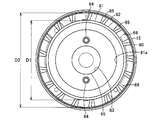
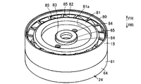
- FIG. 1 It is sectional drawing which shows the electric blower of one Embodiment. It is a top view which shows a part of electric blower same as the above from the centrifugal fan side. It is a perspective view which shows a part of electric blower same as the above from the centrifugal fan side. It is a top view which shows a part of electric blower same as the above from the electric motor side. It is a perspective view which shows a part of electric blower same as the above from the electric motor side. It is a top view which shows the stator of an electric blower same as the above. It is a top view which shows a part of flame
- FIG. 1 to 9 show the electric blower of the embodiment
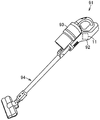
- FIG. 10 shows the electric vacuum cleaner.
- reference numeral 11 denotes an electric blower.
- the electric blower 11 includes an electric motor 13.
- the electric blower 11 includes a centrifugal fan 14. Further, the electric blower 11 includes a diffuser 15 that is a rectifier (rectifier plate).
- the electric blower 11 includes a fan cover 16. The driving of the electric blower 11 (electric motor 13) is controlled by a control circuit (not shown).
- the electric motor 13 may be a commutator motor or a brushless motor, but in the present embodiment, for example, is a single-phase four-pole brushless motor.
- the electric motor 13 includes a rotor 21.
- the electric motor 13 includes a stator 22. Further, the electric motor 13 includes a sensor substrate 23.
- the electric motor 13 includes a frame 24.
- the electric motor 13 in the axial direction of the electric blower 11 is in the rear direction (arrow RR side shown in FIGS. 8 and 9, etc.), and the centrifugal fan 14 side is in the forward direction (arrow FR side shown in FIGS. 8, 9, etc.). ).
- the axial direction and the radial direction refer to the axial direction and the radial direction of the electric blower 11.
- the rotor 21 forms a rotating magnetic pole.
- the rotor 21 is a permanent magnet type rotor in this embodiment, but may be a winding type rotor when the electric motor 13 is a commutator motor.
- the rotor 21 includes a shaft 26.
- the rotor 21 includes a magnet portion 27. Further, the rotor 21 may include at least one sleeve 28.
- the rotor 21 is rotatably held with respect to the frame 24 via a pair of bearings 30.
- the shaft 26 is a rotating shaft that serves as an output shaft of the electric motor 13.
- the centrifugal fan 14 is connected to the shaft 26. Specifically, the centrifugal fan 14 is connected to the shaft 26 on the front end side protruding from the frame 24.
- the magnet part 27 is formed in a cylindrical shape, and a shaft 26 is fixed to the center part.
- a plurality of magnetic poles (rotating magnetic poles) having different polarities in the rotational direction (circumferential direction) are formed adjacent to each other. Therefore, in this magnet portion 27, N poles and S poles are alternately arranged in the rotation direction to form a pair.
- a pair of sleeves 28 are provided in the present embodiment, and are fixed to the shaft 26 adjacent to the front end portion and the rear end portion of the magnet portion 27, respectively.
- the sleeve 28 is not an essential configuration.
- the bearings 30 are attached to one end side and the other end side of the shaft 26, are respectively fixed to the frame 24, and hold the rotor 21 so as to be rotatable with respect to the frame 24.
- the stator 22 shown in FIGS. 6, 8, and 9 constitutes a fixed magnetic pole for rotating the rotor 21.
- the stator 22 includes a stator core 33.
- the stator 22 includes a stator insulating member 34 that is an insulator. Further, the stator 22 includes a coil 35.
- the stator 22 includes a terminal 36.
- the stator core 33 is formed in a plate shape having a substantially constant thickness by laminating thin plate-like magnetic bodies such as electromagnetic steel plates.
- the stator core 33 includes an annular (cylindrical) back yoke 41.
- the stator core 33 includes three or more teeth 42 in this embodiment.
- the stator core 33 includes a frame attachment portion 43.
- the stator core 33 is divided into two in the vertical direction by a substantially semicircular arc shape by the dividing portion 44. That is, the stator core 33 is configured by integrally connecting two (one and other) yoke bodies (core members) 46, 46 punched by, for example, press molding or the like at the dividing portion 44.
- the back yoke 41 connects the teeth 42 to each other, and forms a magnetic path that magnetically couples (by magnetic flux) the fixed magnetic poles generated by the coils 35 and 35 wound around the pair of teeth 42 and 42.
- the back yoke 41 includes first yoke portions 41a and 41a and second yoke portions 41b and 41b.
- the first yoke portions 41 a and the second yoke portions 41 b are alternately arranged in the circumferential direction of the stator core 33.
- the first yoke portions 41a are each formed in an arc shape.
- the first yoke portion 41a is set to have a substantially constant width dimension, and the inner peripheral side gradually becomes wider at a position in the vicinity of the tooth 42 (a position facing the frame mounting portion 43) (see FIG. 4) It is formed.
- a terminal 36 is disposed on the stator insulating member 34 in the first yoke portion 41a.
- the second yoke portions 41b are each formed in an arc shape.
- the second yoke portion 41b is set to have a substantially constant width dimension except for the dividing portion 44.
- the dividing portion 44 is set to the second yoke portion 41b, for example.
- the first yoke portion 41a and the second yoke portion 41b have a circumferential length (a dimension along the circumferential direction of the stator core 33) and a width dimension (a direction along the radial direction of the stator core 33). The dimensions are different from each other.
- the circumferential length (inter-teeth length) of the first yoke portion 41a is set shorter than the circumferential length (inter-teeth length) of the second yoke portion 41b, and the width of the first yoke portion 41a.
- the dimension is set larger than the width dimension of the second yoke portion 41b.
- the first yoke portion 41a is opposite to the center axis side, that is, the inner side (inner peripheral side) and the center axis side of the stator core 33 (back yoke 41) with respect to the second yoke portion 41b. It is formed to be wide on the side, that is, on the outer side (outer peripheral side). That is, the outer diameter dimension of the first yoke part 41a is larger than the outer diameter dimension of the second yoke part 41b, and the inner diameter dimension of the first yoke part 41a is smaller than the inner diameter dimension of the second yoke part 41b. ing. Therefore, the magnetic path of the first yoke portion 41a is set larger (wider) than that of the second yoke portion 41b.
- Teeth 42 have a fixed magnetic pole formed by a coil 35. These teeth 42 are magnetically paired with teeth 42 and 42 located on the left and right.
- the teeth 42 project from the inner peripheral portion of the back yoke 41 toward the center, that is, toward the rotor 21. That is, the teeth 42 are formed in a longitudinal shape along the radial direction of the back yoke 41 (stator core 33), the base end portion is connected to the back yoke 41, and the distal end portion protrudes in a free end shape.
- the teeth 42 adjacent to the left and right are arranged so as to form an angle of 90 ° or less with respect to the circumferential direction of the stator core 33 (stator 22).
- a magnetic action surface facing the outer peripheral surface of the rotor 21 is formed at the tip of each tooth 42. This magnetic action surface is used to cause the fixed magnetic pole formed on each tooth 42 by the coil 35 to act on the rotor 21 and is separated from the outer peripheral surface of the rotor 21 via a slight gap.
- the frame mounting portion 43 is for fixing the stator core 33 (stator 22) to the frame 24.
- the frame attaching portion 43 is formed in a quadrangular shape on the outer side (outer peripheral side) of the back yoke 41 and is disposed in the vicinity of the base end portion of each tooth 42. Therefore, in this embodiment, four frame mounting portions 43 are set, which are numbers that are spaced apart from each other in the circumferential direction of the back yoke 41 and correspond to the teeth 42.
- Each frame attachment portion 43 is provided with an attachment hole 43a penetrating in the axial direction (front-rear direction).
- a screw 49 which is a mounting member, is inserted into the mounting hole 43a, and the stator core 33 (stator 22) is fixed to the frame 24 by screwing the screw 49 to the frame 24 side.
- the stator insulating member 34 holds the coil 35 and the terminal 36 in a state of being insulated from the stator core 33.
- the stator insulating member 34 is formed of an insulating synthetic resin or the like.
- the stator insulating member 34 includes a terminal holding portion 52 that is a terminal block for holding the terminal 36.
- the terminal holding part 52 is disposed so as to overlap the back yoke 41 of the stator core 33.
- two terminal holding portions 52 are arranged on each first yoke portion 41 a of the stator core 33.
- the terminal holding portion 52 is disposed so as to protrude at least partially outward with respect to the stator core 33.
- a part of the terminal holding portion 52 protrudes outward from the outer peripheral edge of the first yoke portion 41a.
- the coil 35 forms a fixed magnetic pole in each tooth 42.
- the coils 35 are arranged so as to generate different polarities alternately in the circumferential direction of the stator core 33 (stator 22), for example.
- the terminal 36 is for electrically connecting the control circuit and each coil 35.
- the terminals 36 are arranged in pairs at positions between the teeth 42, 42 located on the left and right of the stator core 33. And the terminals 36 and 36 located in the left and right form a pair.
- the sensor substrate 23 detects the rotation position (rotation angle) of the rotor 21 by detecting the polarity of the magnetic pole of the rotor 21 (magnet portion 27), and includes, for example, a Hall IC.
- the sensor substrate 23 is formed in a C shape, for example, and is arranged along the outer periphery of the magnet portion 27 of the rotor 21.
- the sensor substrate 23 is stacked on the rear side of the stator 22, for example, and is fixed to the stator insulating member 34 by a substrate fixing member 59 such as a screw.
- the frame 24 is formed of a lightweight and conductive metal member such as aluminum or magnesium.
- the frame 24 includes, for example, one frame body 61 and another frame body 62.
- the frame 24 is configured so that the rotor 21, the stator 22 and the sensor substrate 23 are sandwiched and accommodated from the front and rear by fixing the one and other frame bodies 61 and 62 to each other by screws 49. ing.
- the one frame body 61 is located on the front side with respect to the rotor 21, the stator 22 and the sensor substrate 23. As shown in FIG. 8, the one frame body 61 includes an annular outer portion 64. Further, the one frame body 61 includes one bearing portion 65. Further, one frame body 61 includes one leg portion 66 as a plurality of one connection portion. One frame body 61 includes a plurality of restricting portions 67. Furthermore, the one frame body 61 includes a plurality of screwed portions 68 as attached portions. Further, the one frame body 61 includes a frame intake opening 69 which is an intake opening.
- the outer part 64 sets the maximum outer diameter of the frame 24 (one frame body 61). As shown in FIGS. 3 and 5, the outer portion 64 has an outer diameter dimension substantially equal to that of the diffuser 15.
- one bearing portion 65 is one bearing holding portion that rotatably supports the rotor 21 by receiving one (front side) bearing 30. Further, the one bearing portion 65 is provided with a round hole-like screw hole 65a into which a fixing body 71 such as a screw for fixing the electric motor 13 and the diffuser 15 in the front-rear direction is screwed.
- one leg portion 66 connects one bearing portion 65 and the outer shell portion 64.
- the one leg portion 66 projects radially from the one bearing portion 65.
- a plurality of these one leg portions 66 are provided corresponding to the number of teeth 42 of the stator core 33. That is, four of these one leg portions 66 are provided in this embodiment.
- the one leg portion 66 is substantially equally distributed in the circumferential direction of the frame 24 (one frame body 61). That is, a plurality of these one leg portions 66 are arranged around the electric blower 11 (rotor 21). Further, the one leg portion 66 has a distal end side (outer portion 64 side) bent toward the rear side, that is, the other frame body 62 side.
- the restricting portion 67 positions the frame 24 (one frame body 61) in the circumferential direction with respect to the stator 22 by stopping the stator core 33 from rotating. These restricting portions 67 are provided at the connecting positions of the outer shell portion 64 and the one leg portion 66. The restricting portions 67 are fitted with the frame mounting portions 43, whereby the stator core 33 (the stator 22) is prevented from rotating in the circumferential direction.
- the screwing portion 68 is located on the restricting portion 67 and provided on one leg portion 66, respectively.
- the screw portion 68 is provided in a boss shape to which a screw 49 inserted into the attachment hole 43a of each frame attachment portion 43 of the stator core 33 is screwed.
- the frame intake opening 69 is partitioned between the outer shell 64, one bearing 65, and one adjacent leg 66, 66.
- the frame intake opening 69 is opened to face the diffuser 15.
- the other frame body 62 is located on the rear side with respect to the rotor 21, the stator 22, and the sensor substrate 23.
- the other frame body 62 includes another bearing portion 73.
- the other frame body 62 includes another leg portion 74 as another connecting portion.
- the other bearing portion 73 is another bearing holding portion that rotatably supports the rotor 21 by receiving the other (rear) bearing 30.
- the other leg portion 74 is a contact portion with the stator core 33, and is a portion connecting the other frame body 62 and the one frame body 61. These other leg portions 74 project radially from the other bearing portions 73, respectively. A plurality of these other leg portions 74 are provided corresponding to the number of teeth 42 of the stator core 33, in other words, the number of frame attachment portions 43. That is, four of these other leg portions 74 are provided in this embodiment. Further, these other leg portions 74 are substantially equally distributed in the circumferential direction of the frame 24 (the other frame body 62). That is, a plurality of these other leg portions 74 are arranged around the electric blower 11 (rotor 21).
- these other leg portions 74 are bent at the front end side toward the front side, that is, toward the one frame body 61 side.
- insertion holes 74a through which the screws 49 are inserted are provided at the distal ends of these other leg portions 74, respectively. Then, the screws 49 inserted into the insertion holes 74a of these other leg portions 74 superimposed on the stator core 33 are inserted into the attachment holes 43a of the frame attachment portion 43 of the stator core 33, and the screwing portions 68 of one frame body 61 are inserted. And the other frame bodies 61 and 62 are fixed to each other.
- frame exhaust openings 75 which are exhaust openings, are partitioned. These frame exhaust openings 75 exhaust air that has flowed into the electric motor 13 to the outside. Of the frame exhaust openings 75, the pair of frame exhaust openings 75 facing each other are positioned so that the terminals 36 are exposed.
- the centrifugal fan 14 is connected to the shaft 26 and rotated by the electric motor 13 to push out (blow out) air from the center side to the outer peripheral side.
- the centrifugal fan 14 includes a shaft insertion hole 77 through which the shaft 26 is inserted at the center.
- the centrifugal fan 14 includes a plurality of fan blades 78. Then, the centrifugal fan 14 is integrally fixed to the shaft 26 by screwing a nut 79 as a fixing member into the front end portion of the shaft 26 of the electric motor 13 inserted through the shaft insertion hole 77.
- the diffuser 15 rectifies the air pushed out by the centrifugal fan 14 and flows it into the electric motor 13.
- the diffuser 15 includes an outer frame portion 80.
- the diffuser 15 includes a main body 81.
- the diffuser 15 includes an air passage portion 82 that is a ventilation opening.
- the diffuser 15 includes a mounting opening 83.
- the diffuser 15 includes a through hole 84 that is a fixed hole portion.
- the diffuser 15 includes a plurality of rectifying blades 85.
- the diffuser 15 includes a frame positioning unit 86.
- a fan cover 16 is attached to the front side of the diffuser 15.
- the diffuser 15 is formed of, for example, a synthetic resin, in this embodiment, glass fiber (GF) reinforced PET or the like.
- the outer frame portion 80 supports the frame 24.
- the outer frame portion 80 forms an outer shell of the diffuser 15.
- the outer frame portion 80 is formed in an annular shape having substantially the same diameter as the frame 24, for example. That is, the outer frame portion 80 is set to have an outer diameter dimension substantially equal to the outer shell portion 64. Further, the outer frame portion 80 is overlapped in the axial direction (front side) with respect to the outer shell portion 64 in a state where the frame 24 is supported. Further, the outer frame portion 80 is set to have a larger dimension in the axial direction (front-rear direction) than the main body portion 81. Therefore, the outer frame portion 80 extends so as to protrude in the front-rear direction with respect to the main body portion 81.
- the main body 81 is a portion where the frame 24 is overlapped.
- the main body 81 is disposed inside the outer frame 80.
- the main body 81 is set to have an outer diameter that is larger than the centrifugal fan 14 and smaller than the inner diameter of the outer frame 80. Therefore, the outer edge portion of the main body portion 81 is separated inward (center side) with respect to the inner edge portion of the outer frame portion 80, and is connected by the rectifying blade 85.
- the main body 81 may be provided with a circular concave portion 81a in which the rear side of the centrifugal fan 14 is disposed at the center. Further, the main body 81 is located near the front side in the outer frame 80, for example.
- the air passage portion 82 rectifies the air blown from the centrifugal fan 14 to the frame intake opening 69.
- the air passage portion 82 is formed between the outer frame portion 80 of the diffuser 15 and the main body portion 81 so as to penetrate the diffuser 15 in the front-rear direction.
- a rectifying blade 85 is disposed in the air passage portion 82.
- the air passage portion 82 is defined between the outer frame portion 80, the main body portion 81, and the rectifying blades 85, 85 of the diffuser 15.
- the air passage portion 82 has an inner diameter D 1 and an outer diameter D 2 that are substantially constant, and the inner diameter D 1 is an outer diameter of at least a part of the stator core 33. It is larger than D3 (D1> D3), and the outer diameter D2 is equal to or smaller than the inner diameter D4 of the frame 24 (D2 ⁇ D4).
- the inner diameter D1 of the air passage portion 82 is defined by the outer diameter dimension of the main body portion 81. Further, the outer diameter D2 of the air passage portion 82 is defined by the inner diameter dimension of the outer frame portion 80.
- the outer diameter D3 of the stator core 33 is defined by the outer diameter dimension of the position excluding the frame mounting portion 43, that is, the outer diameter dimension of the back yoke 41.
- the back yoke 41 is provided with a first yoke portion 41a having a relatively large outer diameter and a second yoke portion 41b having a relatively small outer diameter, and the stator core 33
- the outer diameter D2 is defined as an outer diameter dimension at the position of the second yoke portion 41b.
- the inner diameter D4 of the frame 24 is defined by the inner diameter dimension of the outer shell 64 (the inner diameter of the outer shell 64 excluding the restricting portion 67 and the screwing portion 68).
- the diffuser 15 is made of a synthetic resin, and the mold for injection molding is opened along the axial direction from the shape to be removed. Therefore, the diffuser 15 may be provided with a fine draft (taper) along the axial direction.
- the diffuser 15 may be provided with a draft so that the diameter gradually increases from the front side (centrifugal fan 14 side) to the rear side (motor 13 side).
- the outer diameter D2 of the air passage portion 82 defined by the inner diameter of the outer frame portion 80 is the maximum inner diameter of the outer frame portion 80, in other words, the inner diameter of the rear end portion of the outer frame portion 80 in this embodiment.
- the inner diameter of the end of the outer frame 80 on the side of the electric motor 13 (frame 24) that is, the inner diameter of the alignment position (parting position) P between the diffuser 15 (outer frame 80) and the frame 24 (outer section 64)
- the outer diameter D2 of the air passage portion 82 substantially coincides with the inner diameter D4 of the frame 24 at the alignment position P between the diffuser 15 and the frame 24 (D2 ⁇ D4). For this reason, no step is generated at the alignment position P between the diffuser 15 and the frame 24.
- the mounting opening 83 is a part into which the frame 24 is fitted.
- this mounting opening 83 is fitted with one bearing portion 65 of one frame body 61.
- the attachment opening 83 is opened in a circular shape.
- the attachment opening 83 is provided at the center of the main body 81.
- the attachment opening 83 penetrates the recess 81a of the main body 81 in the front-rear direction.
- the through holes 84 are provided on both sides of the mounting opening 83 in the main body 81, for example. In the present embodiment, these through holes 84 respectively penetrate the recesses 81a of the main body 81 in the front-rear direction.
- the rectifying blade 85 connects the outer frame portion 80 and the main body portion 81 of the diffuser 15 and partitions the air passage portion 82. These rectifying blades 85 are provided so as to be inclined from the front side to the rear side along the rotational direction of the centrifugal fan 14 (FIG. 9). Further, as shown in FIGS. 1 and 2, some of the rectifying blades 85 among the rectifying blades 85 are configured so that the frame 24 (one frame body 61) is supported with the frame 24 (the electric motor 13) supported by the diffuser 15. Opposite to. In the present embodiment, a part of the rectifying blades 85 faces one leg 66 of the frame 24 (one frame body 61) in a state where the frame 24 (the electric motor 13) is supported by the diffuser 15. Further, these rectifying blades 85 are provided at substantially equal intervals in the circumferential direction. In the present embodiment, the rectifying blades 85 are provided more than the leg portions 66 of the frame 24 and the fan blades 78 of the centrifugal fan 14.
- the frame positioning portion 86 of the diffuser 15 is a portion into which one leg 66 of one frame body 61 is fitted, for example. Therefore, a plurality of frame positioning portions 86 corresponding to one leg portion 66, that is, four in this embodiment, are provided.
- the frame positioning portion 86 is provided in a groove shape along the front-rear direction, for example, on the inner edge portion on the rear end side (motor 13 side) of the outer frame portion 80.
- the fan cover 16 is attached to the diffuser 15 so as to cover a part of the centrifugal fan 14.
- the fan cover 16 has an air inlet 90 that exposes the central portion of the centrifugal fan 14.
- the control circuit includes, for example, a driver including an inverter circuit and a control unit that performs PWM control on the driver, and is electrically connected to each terminal 36 and the sensor substrate 23.
- This control circuit controls the direction of the current flowing through the coil 35 and the energization time by the driver, thereby switching the magnetic poles generated respectively in the teeth 42 of the stator core 33 of the stator 22 via the coils 35. It is configured as follows.
- the electric blower 11 and the control circuit described above are provided in the vacuum cleaner 91 shown in FIG. 10 in the present embodiment.
- the electric vacuum cleaner 91 includes a vacuum cleaner main body 92 and a dust collector 93.
- a vacuum cleaner 91 in this embodiment, for example, a long stick type (handy type) vacuum cleaner provided with an air passage body 94 that can be attached to and detached from the longitudinal cleaner body 92,
- a canister type or the like, or a self-propelled electric vacuum cleaner capable of autonomous traveling can be suitably used.
- the vacuum cleaner main body 92 houses the electric blower 11 and a control circuit.
- a dust collecting section 93 is detachably attached to the cleaner body 92.
- the dust collection unit 93 is a part that collects dust sucked from the air using the negative pressure generated by driving the electric blower 11 from the air.
- a cyclone dust collecting unit that centrifuges dust is used as the dust collecting unit 93.
- the dust collecting unit 93 filters and collects dust using a filter, or collects dust using inertia. Any configuration can be adopted.
- the air passage body 94 applies a negative pressure generated by driving the electric blower 11 to the floor surface or the like.
- the air passage body 94 is not an essential configuration.
- the electric blower 11 detects the rotational position of the rotor 21 by the sensor board 23, and controls the direction of current flowing in each coil 35 and the energization time by the control circuit according to this rotational position, thereby
- the magnetic poles are sequentially formed, and the rotor 21 is rotated by repulsion / attraction between the magnetic poles and the magnetic poles of the rotor 21. Therefore, air is sucked into the electric blower 11 from the intake port 90 by the negative pressure generated by the rotation of the centrifugal fan 14 of the electric blower 11.
- the sucked air is rectified by the fan blades 78 of the centrifugal fan 14 through the gap between the centrifugal fan 14 and the fan cover 16 to the periphery of the centrifugal fan 14, and then passes through the front side of the diffuser 15. It flows to the surrounding air passage 82.
- this air is rectified by the rectifying blades 85 of the diffuser 15 and flows into the electric motor 13 through the frame intake opening 69, and the stator 22 (stator core 33) and the frame 24 (one frame body 61 (outer portion) 64)) and the interior of the stator 22 (between the teeth 42, 42 of the stator core 33) and passing through the frame 24 of the electric motor 13 while cooling the stator 22 and the rotor 21, each coil 35 and each The terminal 36 is exhausted from the frame exhaust opening 75 while being cooled.
- the inner diameter D1 of the air passage portion 82 is larger than the outer diameter D3 of at least a part of the stator core 33, and the outer diameter D2 of the air passage portion 82 is equal to or smaller than the inner diameter D4 of the frame 24.
- the air blown out from the centrifugal fan 14 and flowing along the air passage portion 82 is exhausted without being disturbed by the outside of the stator core 33 or the inside of the frame 24. Therefore, for example, compared with a case where the inner shape of the frame 24 is a square shape, the air passage between the air passage portion 82 and the outside of the stator core 33 and the inside of the frame 24, that is, the air passage portion, while suppressing an increase in size.
- the air path from 82 to the exhaust can be secured, and the blowing efficiency of the electric blower 11 can be improved.
- the stator core in which the terminal 36 (terminal holding portion 52) is disposed in the air passage portion 82 It is possible to flow air more easily at a position corresponding to the second yoke portion 41b than at a position corresponding to the first yoke portion 41a of 33.
- the air passage portion 82 is blown out from the centrifugal fan 14 along the air passage portion 82.
- the air flowing through the frame 24 can be more reliably prevented from being disturbed by the inside of the frame 24, and turbulence can be prevented from being generated due to a step between the diffuser 15 and the inner periphery of the frame 24. It can be improved.
- the coil 35 forms four or more magnetic poles in the stator core 33, so that the switching of the magnetic flux is smoothed compared to the case of three or less magnetic poles, and the torque of the motor 13 is improved.
- the efficiency of the electric blower 11 is further improved.
- the substantially circular (substantially annular) stator core 33 can be wound for each semi-circular (semi-arc) yoke body 46, for example.
- the coil 35 can be easily configured and the productivity can be improved.
- the yoke bodies 46, each of which constitutes the coil 35, at the dividing portion 44 the circular stator 22 can be easily configured.
- the stator core 33 includes a first yoke portion 41a having a relatively large outer diameter and a second yoke portion 41b having a relatively small outer diameter on the back yoke 41.
- it can also be formed as a substantially constant outer diameter.
- the outer diameter D3 of a part of the stator core 33 can be made smaller than the inner diameter D1 of the air passage portion 82.
- the electric blower 11 has been described as being applied for suction of the electric vacuum cleaner 91, the electric blower 11 may be applied for exhaust of, for example, a blower.
- the electric blower 11 can be used for any electric equipment other than the vacuum cleaner 91.
Landscapes
- Engineering & Computer Science (AREA)
- Power Engineering (AREA)
- Mechanical Engineering (AREA)
- General Engineering & Computer Science (AREA)
- Physics & Mathematics (AREA)
- Thermal Sciences (AREA)
- Structures Of Non-Positive Displacement Pumps (AREA)
- Motor Or Generator Frames (AREA)
- Motor Or Generator Cooling System (AREA)
Abstract
L'invention concerne une soufflante électrique qui, selon un mode de réalisation, comprend un ventilateur centrifuge, un moteur électrique et un redresseur de flux. Un diffuseur est pourvu d'une partie châssis externe, d'une partie corps et d'une partie conduit d'air. La partie châssis externe soutient un châssis et forme une coque externe. La partie corps est disposée à l'intérieur de la partie coque externe. La partie conduit d'air est formée entre la partie châssis externe et la partie corps et redresse l'air soufflé depuis le ventilateur centrifuge en direction d'une partie ouverture d'admission d'air du châssis. La partie conduit d'air a un diamètre interne D1 supérieur au diamètre externe D3 d'au moins une partie d'un noyau de stator, et un diamètre externe D2 qui est défini pour être inférieur ou égal au diamètre interne D4 du châssis.
Priority Applications (1)
| Application Number | Priority Date | Filing Date | Title |
|---|---|---|---|
| CN201780040109.XA CN109416055A (zh) | 2016-11-21 | 2017-09-08 | 电动鼓风机以及电动吸尘器 |
Applications Claiming Priority (2)
| Application Number | Priority Date | Filing Date | Title |
|---|---|---|---|
| JP2016226065A JP6718365B2 (ja) | 2016-11-21 | 2016-11-21 | 電動送風機および電気掃除機 |
| JP2016-226065 | 2016-11-21 |
Publications (1)
| Publication Number | Publication Date |
|---|---|
| WO2018092393A1 true WO2018092393A1 (fr) | 2018-05-24 |
Family
ID=62145522
Family Applications (1)
| Application Number | Title | Priority Date | Filing Date |
|---|---|---|---|
| PCT/JP2017/032513 Ceased WO2018092393A1 (fr) | 2016-11-21 | 2017-09-08 | Soufflante électrique et aspirateur électrique |
Country Status (3)
| Country | Link |
|---|---|
| JP (1) | JP6718365B2 (fr) |
| CN (1) | CN109416055A (fr) |
| WO (1) | WO2018092393A1 (fr) |
Families Citing this family (11)
| Publication number | Priority date | Publication date | Assignee | Title |
|---|---|---|---|---|
| KR102200088B1 (ko) * | 2019-02-20 | 2021-01-11 | 엘지전자 주식회사 | 팬 모터 |
| JP7354569B2 (ja) * | 2019-03-28 | 2023-10-03 | ニデック株式会社 | 送風装置、および掃除機 |
| CN111202464B (zh) * | 2020-02-27 | 2023-12-05 | 刘慕华 | 一种吸尘器 |
| KR102797009B1 (ko) * | 2020-05-08 | 2025-04-18 | 엘지전자 주식회사 | 모터 어셈블리 |
| KR102786156B1 (ko) * | 2020-06-11 | 2025-03-26 | 삼성전자주식회사 | 모터 어셈블리 및 이를 포함하는 청소기 |
| KR102762815B1 (ko) * | 2020-07-20 | 2025-02-05 | 엘지전자 주식회사 | 모터 조립체 및 이를 구비한 헤어드라이어 |
| KR102824015B1 (ko) * | 2020-07-28 | 2025-06-23 | 엘지전자 주식회사 | 팬 모터 및 이를 포함하는 헤어드라이어 |
| CN114183382B (zh) | 2020-09-14 | 2025-06-17 | 北京石头世纪科技股份有限公司 | 一种风机及清洁设备 |
| US11795967B2 (en) | 2020-12-23 | 2023-10-24 | Makita Corporation | Blower |
| JP2022100054A (ja) * | 2020-12-23 | 2022-07-05 | 株式会社マキタ | 送風機 |
| US11802573B2 (en) | 2020-12-23 | 2023-10-31 | Makita Corporation | Blower |
Citations (8)
| Publication number | Priority date | Publication date | Assignee | Title |
|---|---|---|---|---|
| JPS5117808U (fr) * | 1974-07-29 | 1976-02-09 | ||
| JPS61252896A (ja) * | 1985-04-30 | 1986-11-10 | Matsushita Electric Ind Co Ltd | 電動送風機 |
| JPH11336700A (ja) * | 1998-05-25 | 1999-12-07 | Matsushita Electric Ind Co Ltd | 電動送風機 |
| JP2010059811A (ja) * | 2008-09-02 | 2010-03-18 | Panasonic Corp | 電動送風機及びそれを用いた電気掃除機 |
| JP2015034514A (ja) * | 2013-08-09 | 2015-02-19 | 日本電産株式会社 | 送風装置および掃除機 |
| JP2016211533A (ja) * | 2015-04-28 | 2016-12-15 | 日本電産株式会社 | 送風装置および掃除機 |
| JP2016223432A (ja) * | 2015-05-29 | 2016-12-28 | 日本電産株式会社 | インペラ、送風装置、および掃除機 |
| JP2017053347A (ja) * | 2015-08-21 | 2017-03-16 | ジョンソン エレクトリック ソシエテ アノニム | ディフューザ、気流発生装置、及び電気装置 |
Family Cites Families (5)
| Publication number | Priority date | Publication date | Assignee | Title |
|---|---|---|---|---|
| JP3724413B2 (ja) * | 2001-11-05 | 2005-12-07 | 松下電器産業株式会社 | 電気掃除機用電動送風機及びこれを用いた電気掃除機 |
| KR20120134505A (ko) * | 2011-06-02 | 2012-12-12 | 삼성전기주식회사 | 스위치드 릴럭턴스 모터 |
| KR102274393B1 (ko) * | 2014-08-11 | 2021-07-08 | 삼성전자주식회사 | 진공청소기 |
| CN106469966A (zh) * | 2015-08-18 | 2017-03-01 | 德昌电机(深圳)有限公司 | 气流产生装置及吸尘器、干手器、干发器、吹风机 |
| CN205064381U (zh) * | 2015-08-21 | 2016-03-02 | 德昌电机(深圳)有限公司 | 扩散器、气流产生装置及吸尘器、干手机、吹风机 |
-
2016
- 2016-11-21 JP JP2016226065A patent/JP6718365B2/ja active Active
-
2017
- 2017-09-08 WO PCT/JP2017/032513 patent/WO2018092393A1/fr not_active Ceased
- 2017-09-08 CN CN201780040109.XA patent/CN109416055A/zh active Pending
Patent Citations (8)
| Publication number | Priority date | Publication date | Assignee | Title |
|---|---|---|---|---|
| JPS5117808U (fr) * | 1974-07-29 | 1976-02-09 | ||
| JPS61252896A (ja) * | 1985-04-30 | 1986-11-10 | Matsushita Electric Ind Co Ltd | 電動送風機 |
| JPH11336700A (ja) * | 1998-05-25 | 1999-12-07 | Matsushita Electric Ind Co Ltd | 電動送風機 |
| JP2010059811A (ja) * | 2008-09-02 | 2010-03-18 | Panasonic Corp | 電動送風機及びそれを用いた電気掃除機 |
| JP2015034514A (ja) * | 2013-08-09 | 2015-02-19 | 日本電産株式会社 | 送風装置および掃除機 |
| JP2016211533A (ja) * | 2015-04-28 | 2016-12-15 | 日本電産株式会社 | 送風装置および掃除機 |
| JP2016223432A (ja) * | 2015-05-29 | 2016-12-28 | 日本電産株式会社 | インペラ、送風装置、および掃除機 |
| JP2017053347A (ja) * | 2015-08-21 | 2017-03-16 | ジョンソン エレクトリック ソシエテ アノニム | ディフューザ、気流発生装置、及び電気装置 |
Also Published As
| Publication number | Publication date |
|---|---|
| JP2018084151A (ja) | 2018-05-31 |
| JP6718365B2 (ja) | 2020-07-08 |
| CN109416055A (zh) | 2019-03-01 |
Similar Documents
| Publication | Publication Date | Title |
|---|---|---|
| JP6718365B2 (ja) | 電動送風機および電気掃除機 | |
| JP6599791B2 (ja) | 電動送風機および電気掃除機 | |
| JP7090767B2 (ja) | モータ、送風機、電気掃除機および手乾燥装置 | |
| US20210050762A1 (en) | Electric blower, electric vacuum cleaner, and hand drier | |
| JP6791692B2 (ja) | 電動送風機 | |
| US11894721B2 (en) | Stator, electric motor, vacuum cleaner, and hand drying device | |
| CN111630751B (zh) | 定子、电机、送风机、电动吸尘器及手干燥装置 | |
| US11268532B2 (en) | Electric blower, electric vacuum cleaner, and hand dryer | |
| JP7225752B2 (ja) | 送風装置および掃除機 | |
| JP2015142497A (ja) | ブラシレスモータおよびその製造方法 | |
| JP6796465B2 (ja) | 電動送風機および電気掃除機 | |
| JP7190368B2 (ja) | ブラシレスモータおよび電動送風機 | |
| CN109314411B (zh) | 电动鼓风机 | |
| JP6859074B2 (ja) | 電動機および電気掃除機 | |
| JP2018084150A (ja) | 電動送風機、電気掃除機および電動送風機の製造方法 | |
| JP6827198B2 (ja) | ブラシレスモータおよび電動工具 | |
| CN209483691U (zh) | 电动送风机以及电动吸尘器 | |
| JP6948274B2 (ja) | 電動送風機および電気掃除機 | |
| JP7058196B2 (ja) | 電動送風機及びその製造方法 | |
| JP6526941B2 (ja) | ブラシレスモータ | |
| JP2018123814A (ja) | 電動送風機および電気掃除機 | |
| CN110476333A (zh) | 电动鼓风机以及电动吸尘器 | |
| JP2019187111A (ja) | ブラシレスモータおよび電動送風機 | |
| JPWO2019211965A1 (ja) | 電動機及び電動送風機 | |
| JP2018074859A (ja) | ロータ、電動機および電気掃除機 |
Legal Events
| Date | Code | Title | Description |
|---|---|---|---|
| 121 | Ep: the epo has been informed by wipo that ep was designated in this application |
Ref document number: 17872465 Country of ref document: EP Kind code of ref document: A1 |
|
| NENP | Non-entry into the national phase |
Ref country code: DE |
|
| 122 | Ep: pct application non-entry in european phase |
Ref document number: 17872465 Country of ref document: EP Kind code of ref document: A1 |