WO2018092514A1 - Procédé de détection de quantité de divergence dans le soudage par suivi d'arc - Google Patents
Procédé de détection de quantité de divergence dans le soudage par suivi d'arc Download PDFInfo
- Publication number
- WO2018092514A1 WO2018092514A1 PCT/JP2017/038085 JP2017038085W WO2018092514A1 WO 2018092514 A1 WO2018092514 A1 WO 2018092514A1 JP 2017038085 W JP2017038085 W JP 2017038085W WO 2018092514 A1 WO2018092514 A1 WO 2018092514A1
- Authority
- WO
- WIPO (PCT)
- Prior art keywords
- welding
- waveform
- fitting
- weaving
- function
- Prior art date
- Legal status (The legal status is an assumption and is not a legal conclusion. Google has not performed a legal analysis and makes no representation as to the accuracy of the status listed.)
- Ceased
Links
Images









Classifications
-
- B—PERFORMING OPERATIONS; TRANSPORTING
- B23—MACHINE TOOLS; METAL-WORKING NOT OTHERWISE PROVIDED FOR
- B23K—SOLDERING OR UNSOLDERING; WELDING; CLADDING OR PLATING BY SOLDERING OR WELDING; CUTTING BY APPLYING HEAT LOCALLY, e.g. FLAME CUTTING; WORKING BY LASER BEAM
- B23K9/00—Arc welding or cutting
- B23K9/12—Automatic feeding or moving of electrodes or work for spot or seam welding or cutting
- B23K9/127—Means for tracking lines during arc welding or cutting
- B23K9/1272—Geometry oriented, e.g. beam optical trading
- B23K9/1276—Using non-contact, electric or magnetic means, e.g. inductive means
-
- B—PERFORMING OPERATIONS; TRANSPORTING
- B23—MACHINE TOOLS; METAL-WORKING NOT OTHERWISE PROVIDED FOR
- B23K—SOLDERING OR UNSOLDERING; WELDING; CLADDING OR PLATING BY SOLDERING OR WELDING; CUTTING BY APPLYING HEAT LOCALLY, e.g. FLAME CUTTING; WORKING BY LASER BEAM
- B23K9/00—Arc welding or cutting
- B23K9/12—Automatic feeding or moving of electrodes or work for spot or seam welding or cutting
- B23K9/127—Means for tracking lines during arc welding or cutting
- B23K9/1272—Geometry oriented, e.g. beam optical trading
-
- B—PERFORMING OPERATIONS; TRANSPORTING
- B23—MACHINE TOOLS; METAL-WORKING NOT OTHERWISE PROVIDED FOR
- B23K—SOLDERING OR UNSOLDERING; WELDING; CLADDING OR PLATING BY SOLDERING OR WELDING; CUTTING BY APPLYING HEAT LOCALLY, e.g. FLAME CUTTING; WORKING BY LASER BEAM
- B23K31/00—Processes relevant to this subclass, specially adapted for particular articles or purposes, but not covered by any single one of main groups B23K1/00 - B23K28/00
- B23K31/12—Processes relevant to this subclass, specially adapted for particular articles or purposes, but not covered by any single one of main groups B23K1/00 - B23K28/00 relating to investigating the properties, e.g. the weldability, of materials
- B23K31/125—Weld quality monitoring
-
- B—PERFORMING OPERATIONS; TRANSPORTING
- B23—MACHINE TOOLS; METAL-WORKING NOT OTHERWISE PROVIDED FOR
- B23K—SOLDERING OR UNSOLDERING; WELDING; CLADDING OR PLATING BY SOLDERING OR WELDING; CUTTING BY APPLYING HEAT LOCALLY, e.g. FLAME CUTTING; WORKING BY LASER BEAM
- B23K9/00—Arc welding or cutting
- B23K9/095—Monitoring or automatic control of welding parameters
- B23K9/0953—Monitoring or automatic control of welding parameters using computing means
-
- B—PERFORMING OPERATIONS; TRANSPORTING
- B23—MACHINE TOOLS; METAL-WORKING NOT OTHERWISE PROVIDED FOR
- B23K—SOLDERING OR UNSOLDERING; WELDING; CLADDING OR PLATING BY SOLDERING OR WELDING; CUTTING BY APPLYING HEAT LOCALLY, e.g. FLAME CUTTING; WORKING BY LASER BEAM
- B23K9/00—Arc welding or cutting
- B23K9/12—Automatic feeding or moving of electrodes or work for spot or seam welding or cutting
-
- B—PERFORMING OPERATIONS; TRANSPORTING
- B23—MACHINE TOOLS; METAL-WORKING NOT OTHERWISE PROVIDED FOR
- B23K—SOLDERING OR UNSOLDERING; WELDING; CLADDING OR PLATING BY SOLDERING OR WELDING; CUTTING BY APPLYING HEAT LOCALLY, e.g. FLAME CUTTING; WORKING BY LASER BEAM
- B23K9/00—Arc welding or cutting
- B23K9/12—Automatic feeding or moving of electrodes or work for spot or seam welding or cutting
- B23K9/127—Means for tracking lines during arc welding or cutting
Definitions
- the robot motion trajectory (tracing trajectory) during welding depends on the welding conditions (current, voltage, welding speed, weaving width, weaving frequency) and the scanning parameters (offset of gain and left / right current difference). May change. That is, during actual welding, deviation from the weld line occurs due to various factors.
- a consumable electrode type arc welding method is disclosed in which the movement of the center position of the weaving width of the welding torch is controlled in accordance with the deviation.
- Patent Documents 1 and 2 disclose various technologies, they are not sufficient to solve the problem intended by the present application.
- the center position of the weaving is correctly aligned with the weld line based on the difference current value between the maximum current value and the minimum current value at the right end and the left end during weaving.
- this technology uses only four points of information in one weaving cycle, and since it is simply added and subtracted, there is a risk of increasing the effect of variation.
- the deviation detection method in arc copy welding employs the following technical means. That is, according to the present invention, the deviation detection method in arc profiling welding is performed in the arc profiling welding in which welding is performed along the welding line while performing a weaving operation of swinging the torch in the welding direction.
- a deviation amount detection method in arc scanning welding that detects a deviation amount from a position, and fitting a waveform represented by a function that repeats periodically at the same cycle as a weaving cycle to a waveform of a welding current or a welding voltage, It is characterized in that a deviation amount in arc copy welding is detected based on the fitted waveform.
- At least one of a sine wave and a cosine wave having the same period as the weaving period is used as the waveform represented by the function.
- the waveform represented by the function at least one of a sine wave and a cosine wave having the same period as the weaving period is used, and a sine wave having a half period of the weaving period. It is preferable to use at least one of a cosine wave.
- a weaving waveform is used as the waveform represented by the function.
- the obtained welding current or welding voltage data is stored for a certain period, and the stored welding current is stored.
- fitting may be performed using welding voltage data.
- the calculation of calculating the average of the results of the sequential fitting is performed every predetermined time while performing the sequential fitting.
- a personal computer that is, an off-line teaching system includes a display capable of graphic display, and includes a keyboard or a mouse as an input device.
- a storage device or a communication device is provided to capture CAD information of the workpiece.
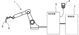
- the arc copy welding method according to the present embodiment is realized as a program provided in the control device 3.
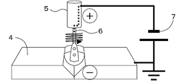
- FIG. 9B shows a schematic diagram of arc welding.
- arc welding a voltage is applied between the welding wire 6 (consumable electrode) supplied from the welding torch 5 and the base material 4 by the welding power source of the power supply device 7, and an arc is generated between the welding wire 6 and the base material 4.
- the base material 4 and the welding wire 6 are melted by the arc heat, welding is performed. Since the welding wire 6 melts with arc welding, the welding wire 6 continues to be supplied via the inside of the welding torch 5 by the feeding device during welding.
- the weld metal in which the base material 4 and the welding wire 6 are melted is solidified to form a weld bead, thereby realizing strong welding.
- medium thickness plate welding represented by welding of thick steel plates
- a shield gas is also supplied from the welding torch 5 to protect the arc column formed at the tip of the welding torch 5 from the atmosphere. Furthermore, the molten metal after melting is also protected from the atmosphere by the gas generated by the decomposition of the flux contained in the welding wire 6 to suppress welding defects such as blow holes.
- the welding line that is the position to be welded such as poor welding workpiece machining accuracy, poor welding workpiece installation accuracy, or deformation of the welding workpiece due to thermal strain during welding, may occur. It is not always in a fixed position. Weld line misalignment generally occurs on the order of several millimeters to centimeters.
- the deviation from the welding line allowed for the arc welding robot 1 in the thick plate field from the viewpoint of welding quality is generally less than 1 mm, and it cannot be welded by a playback type robot operating at a predetermined position.
- the medium-thickness plate welding robot 1 detects the deviation between the welding position taught in advance and the welding position of the actual workpiece in real time, and adapts to this each time to “follow” the welding line with sub-mm order accuracy. Is an essential requirement and one of the most important functions that is indispensable.
- processing for detecting the amount of deviation of the position of the torch tip with respect to the weld line is performed in the control unit. If the displacement amount detection process as shown below is performed, the displacement amount can be detected more accurately than before, and therefore, when performing arc copy welding, it is possible to perform control to reduce displacement from the weld line as much as possible. It becomes possible.
- the shift amount detection process of the present embodiment performs the following processes (i) to (iv).
- the difference between the maximum value and the minimum value of the waveform of the fitted function is regarded as a current difference or a voltage difference corresponding to the shift amount, and the shift amount is obtained from the difference between the maximum value and the minimum value of the function waveform.
- the function may be a function in which a plurality of waveforms are superimposed as long as the function repeats periodically in the same period as the weaving period. However, at least one waveform that always includes one maximum value and one minimum value is used. Using such a function, the deviation amount may be obtained from the difference between the maximum value and the minimum value.
- the left end point and right end point information of the weaving operation the value of the welding current or welding voltage when the welding torch 5 is positioned at the left end point or the right end point of the weaving waveform
- the amount of deviation can be estimated using information on each point during welding (the value of the welding current or welding voltage when the welding torch 5 is positioned between the left end point and the right end point), and the detection accuracy is improved. It becomes possible.
- the weaving waveform is known, it is not necessary to obtain a waveform to be fitted as in Patent Document 2.
- the weaving waveform is prescribed, and it is only necessary to prepare a function that repeats periodically in the same period as the weaving period. Therefore, a preliminary experiment is performed to obtain a waveform for fitting or acquire data for that purpose. There is no need to do.
- a sine wave and a cosine wave having the same period as the weaving period as a function to be used.
- the phase difference during the fitting that is, the position of the welding current waveform and the position of the welding robot 1 is determined by the trigonometric synthesis formula. There will be an advantage that it is not necessary to consider the phase difference.
- each of the obtained welding current or welding voltage data is sequentially used. Alternatively, sequential fitting may be performed. Further, the obtained welding current or welding voltage data may be stored for a certain period, and fitting may be performed using the stored welding current or welding voltage data.
- the waveform of the welding current or welding voltage for one cycle of weaving is stored and the obtained waveform is obtained.
- the fitting process may be performed based on the welding current or welding voltage data obtained at each control cycle.
- the weaving period is at most 2 to 10 Hz, that is, the arc scanning can only be corrected every 500 msec to 100 msec.
- the fitting operation is performed sequentially, the current or voltage of the welding power source 7 can be acquired.
- the arc scanning is corrected for each cycle. In other words, scanning is corrected every 1 msec to 10 msec, and a smoother robot motion trajectory is obtained during arc scanning.
- the processing (iv) will be described in detail in Example 1.
- the deviation amount detection method according to the second embodiment includes at least one of a sine wave and a cosine wave in which the processes (ii) and (iii) of the first embodiment have the same period as the weaving period, or 1 / of the weaving period.
- the second embodiment performs the fitting operation using a function (non-trigonometric function) other than the trigonometric function. It is to do.
- Example 1 In the first embodiment, fitting (matching of welding current and sine wave) is performed using a sine wave on the waveform of the welding current obtained for each weaving cycle. In other words, the least square method is used for each weaving cycle. The fitting is performed by the above process, and the amount of deviation from the weld line is detected.
- Equation (1) n equations including the coefficients p 1 and p 2 can be obtained, and the amplitude p 1 can be obtained by using the least square method.
- Equation (1) the phase shift is ⁇ and the sine wave is used as a function.
- ⁇ a function in which a sine wave and a cosine wave are superimposed is used as shown in Equation (2). Also good.
- the amplitude qs of the sine wave component and the amplitude qc of the cosine wave component of the equation (2) can be obtained using the least square method. Thereafter, the combined amplitude is obtained from the equation (3) using trigonometric function combining.
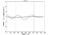
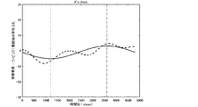
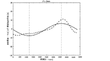
- the expression (1) was applied while changing the position of the welding torch 5 from the weld line to 0 mm, 1 mm, 2 mm, 3 mm, and 4 mm.
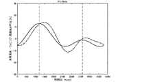
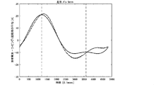
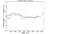
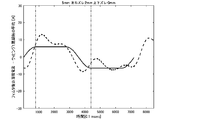
- the results of applying equation (1) are shown in FIGS. 2A-2E. 2A to 2E, a representative one of the waveforms for 50 weaving (for 50 cycles) is selected and indicated by a broken line.
- the solid line shows the result of fitting using the sine wave of equation (1) as a function.
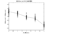
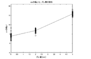
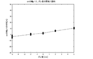
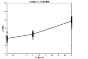
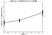
- FIG. 3B shows the result of fitting using the equation (1) to obtain the amplitude p 1 of the function, and arranging the same for each set value of the deviation amount from the weld line.
- Distribution width of the amplitude p 1 function extending in the vertical axis direction in FIG. 3B shows a variation of the amplitude measured by the method of Example 1.
- FIG. 3A showing the current difference between left and right measured by the above-described conventional method is compared with FIG. 3B showing the amplitude variation measured by the method of the first embodiment. For example, attention is paid to a value of 0 mm and a value of 4 mm.
- the amplitude p 1 calculated by the method of the first embodiment has a smaller vertical range of variation than the left and right current difference (amplitude obtained by the conventional method) calculated by the conventional method.
- the amplitude p 1 that is, the amount of deviation from the weld line can be accurately detected.
- p 1 and p 2 can be obtained sequentially using data for the past one period.
- the amount of deviation is obtained every time data is acquired, and the amount of deviation can be obtained more quickly without waiting for one cycle of weaving. Further, there is an advantage that a continuous shift amount can be obtained. Furthermore, it is also possible to perform a fitting operation on the obtained welding current or welding voltage data for Example 1 each time (sequential fitting).
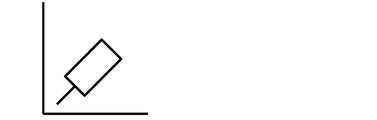
- Example 2 a horizontal fillet as schematically shown in FIG. 4 is fitted using a least square method using a trigonometric function as a function to detect a deviation from the weld line.
- the function of the second embodiment is a combination of a sine waveform (Sin waveform) having the same period as the weaving period and a sine waveform having a half period. Specifically, in the second embodiment, fitting is performed based on y (t) obtained for each weaving cycle, and the amplitudes p 1, p 2 , and p 3 in Expression (5) are obtained. In the function of the second embodiment shown by the equation (5), the phase difference of the sine waveform is 0, but the sine waveform having a period of 1/2 is the phase difference ⁇ / 2. The reason why the phase difference of ⁇ / 2 is provided in this way is to make the sine wave peak with a half period coincide with the position of the end signal of the weaving.
- the amplitude p 1 after fitting can be obtained. .
- FIG. 6B shows the result obtained by calculating the amplitude p 1 of the function that was fitted using the equation (1), and arranging it for each set value of the deviation amount from the weld line. Similar to FIG. 3B, the distribution width of the amplitude p 1 of the function spreading in the vertical axis direction in FIG. 6B indicates the variation in amplitude measured by the method of the first embodiment.
- the amplitude p 1 obtained by the method of Example 2 is larger than the current difference between left and right (amplitude obtained by the conventional method). It can also be seen that the size of the variation has decreased. Also, using the original welding current waveform, a sinusoidal waveform with the same period as the weaving period and a sinusoidal waveform with a half period of the weaving period are used as functions, and the amplitude is obtained by the least square method for fitting. If it carries out, it turns out that the original welding current waveform can be reproduced substantially.
- the data storage memory can be reduced when current waveforms and voltage waveforms are stored in a control device or personal computer as in recent years, and the waveforms are checked or traced later. It is clear that it can be applied to. That is, if the current waveform or voltage waveform is not stored as sampling data as it is, but once fitted using Equation (5) and saved as p 1 , p 2 , p 3 , the amplitude information of the waveform Without losing memory, the amount of memory such as a hard disk can be greatly reduced, and the cost can be reduced.
- Example 3 uses a function of a non-trigonometric function for fitting instead of a trigonometric function such as a sine waveform or a cosine waveform as a function.
- a trigonometric function such as a sine waveform or a cosine waveform as a function.
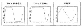
- the weaving waveform of this Example 3 is “Sin + Both end stop” shown on the left side of FIG. 7, and the function used for fitting is “Sin + Both end stop” shown on the left side of FIG. It has become.
- a weaving waveform represented by a function consisting of a trigonometric function or a non-trigonometric function is fitted to a waveform of a welding current or welding voltage, and the amplitude of the fitted waveform is used as a basis.
- Example 4 when the fitting is performed sequentially while following the method of the above-described embodiments (the first to third embodiments), the average of the results of the sequential fitting is taken for each weaving cycle. A technique is disclosed in which the accuracy can be further improved as compared with the case of simply fitting every one period.
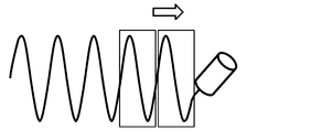
- FIG. 10 schematically shows a case where the fitting is simply performed every weaving cycle.
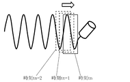
- FIG. 11 schematically shows a technique (technique of the fourth embodiment) that averages the results of sequential fitting for each period of weaving while performing sequential fitting.
- calculation is performed by averaging the results of the sequential fitting for each period of weaving while performing the sequential fitting. The specific method of the calculation is as follows.
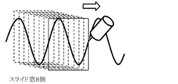
- the window performs fitting while sliding the (interval), previously obtained sequentially, p 1 (tn), p 1 and (tn + 1) .
- FIG. 12A shows the result of fitting using equation (1) to obtain the function amplitude p 1 and arranging it for each set value of the deviation amount from the weld line.
- FIG. 12B shows the function amplitudes p 1 (tn) to p 1 (tn + (n ⁇ 1)) obtained by fitting using the equation (6), the average amplitude p Ave is obtained using the equation (7), and welding is performed. The result arranged for each set value of the deviation amount from the line is shown.
- FIG. 12A is compared with FIG. 12B showing the variation in amplitude measured by the method of the fourth embodiment.
- FIG. 13A to 13C schematically show how many sequential fittings are performed for each weaving cycle.
- FIG. 13A shows an example in which the number of sliding windows is two, in other words, the calculation is advanced by sliding the section only once.
- FIG. 13B shows an example in which the calculation is advanced by sliding the section three times when there are four sliding windows.
- FIG. 13C shows an example in which the number of sliding windows is 8, in other words, the calculation is advanced by sliding the section seven times.
- FIG. 14 shows the number of sequential fittings per weaving cycle and the standard deviation of the average p Ave of the sequential fitting results per weaving cycle when the number of sequential fittings is changed as shown in FIGS. 13A to 13C. This shows the relationship.
- the fourth embodiment it is possible to realize the copy welding with higher accuracy by sequentially averaging the results of the fitting every weaving cycle.
- the embodiment disclosed this time should be considered as illustrative in all points and not restrictive.
- matters that are not explicitly disclosed, for example, operating conditions and operating conditions, various parameters, dimensions, weights, volumes, and the like of a component deviate from a range that a person skilled in the art normally performs. Instead, values that can be easily assumed by those skilled in the art are employed. For example, even in the case of weaving that swings obliquely with respect to the welding direction, it is possible to detect the amount of deviation similarly by fitting with a function having the same period as the weaving period.
Landscapes
- Engineering & Computer Science (AREA)
- Physics & Mathematics (AREA)
- Mechanical Engineering (AREA)
- Plasma & Fusion (AREA)
- Geometry (AREA)
- Quality & Reliability (AREA)
- Theoretical Computer Science (AREA)
- Butt Welding And Welding Of Specific Article (AREA)
- Manipulator (AREA)
Abstract
Dans ce procédé de détection d'une quantité de divergence dans le soudage par suivi d'arc, une quantité de divergence entre une ligne de soudage et une position de soudage réelle est détectée dans un soudage par suivi d'arc dans lequel un soudage est effectué le long de ladite ligne de soudage tandis qu'une action de tissage est effectuée pour amener un chalumeau à osciller par rapport à une direction de soudage. Une forme d'onde représentée par une fonction qui se répète périodiquement avec la même période qu'une période de tissage est ajustée à une forme d'onde d'un courant de soudage ou d'une tension de soudage, et la quantité de divergence dans le soudage par suivi d'arc est détectée sur la base de la forme d'onde ajustée.
Priority Applications (4)
| Application Number | Priority Date | Filing Date | Title |
|---|---|---|---|
| US16/349,213 US11235414B2 (en) | 2016-11-16 | 2017-10-20 | Method of detecting amount of discrepancy in arc tracking welding |
| CN201780070055.1A CN109963679B (zh) | 2016-11-16 | 2017-10-20 | 电弧跟踪焊接中的偏移量的检测方法 |
| EP17870900.2A EP3542944A4 (fr) | 2016-11-16 | 2017-10-20 | Procédé de détection de quantité de divergence dans le soudage par suivi d'arc |
| KR1020197013335A KR102152049B1 (ko) | 2016-11-16 | 2017-10-20 | 아크 트래킹 용접에서의 어긋남양 검출 방법 |
Applications Claiming Priority (4)
| Application Number | Priority Date | Filing Date | Title |
|---|---|---|---|
| JP2016-223233 | 2016-11-16 | ||
| JP2016223233 | 2016-11-16 | ||
| JP2017-174918 | 2017-09-12 | ||
| JP2017174918A JP6776493B2 (ja) | 2016-11-16 | 2017-09-12 | アーク倣い溶接でのズレ量検出方法 |
Publications (1)
| Publication Number | Publication Date |
|---|---|
| WO2018092514A1 true WO2018092514A1 (fr) | 2018-05-24 |
Family
ID=62145468
Family Applications (1)
| Application Number | Title | Priority Date | Filing Date |
|---|---|---|---|
| PCT/JP2017/038085 Ceased WO2018092514A1 (fr) | 2016-11-16 | 2017-10-20 | Procédé de détection de quantité de divergence dans le soudage par suivi d'arc |
Country Status (2)
| Country | Link |
|---|---|
| US (1) | US11235414B2 (fr) |
| WO (1) | WO2018092514A1 (fr) |
Families Citing this family (1)
| Publication number | Priority date | Publication date | Assignee | Title |
|---|---|---|---|---|
| CN111843120B (zh) * | 2020-08-07 | 2022-01-07 | 北京时代科技股份有限公司 | 基于电弧传感和位置前馈的机器人焊缝跟踪算法 |
Citations (6)
| Publication number | Priority date | Publication date | Assignee | Title |
|---|---|---|---|---|
| JPS5853375A (ja) | 1981-09-24 | 1983-03-29 | Kobe Steel Ltd | 消耗電極式ア−ク溶接方法 |
| JPS59120369A (ja) * | 1982-12-27 | 1984-07-11 | Hitachi Ltd | 溶接線倣い制御方法および装置 |
| JPH0259180A (ja) * | 1988-08-25 | 1990-02-28 | Matsushita Electric Ind Co Ltd | アーク溶接信号処理装置 |
| JP2004098162A (ja) | 2002-07-17 | 2004-04-02 | Yaskawa Electric Corp | 溶接線倣い制御方法 |
| JP2016223233A (ja) | 2015-06-03 | 2016-12-28 | 大成建設株式会社 | 制振構造 |
| JP2017174918A (ja) | 2016-03-23 | 2017-09-28 | 東京エレクトロン株式会社 | 窒化膜の形成方法 |
Family Cites Families (9)
| Publication number | Priority date | Publication date | Assignee | Title |
|---|---|---|---|---|
| JPS59183971A (ja) | 1983-03-31 | 1984-10-19 | Mitsubishi Electric Corp | 溶接線追従センサ |
| JPS60124475A (ja) * | 1983-12-09 | 1985-07-03 | Hitachi Ltd | 溶接線倣い制御方法および装置 |
| JPS6137376A (ja) * | 1984-07-30 | 1986-02-22 | Mitsubishi Electric Corp | 溶接線追従装置 |
| JPS61144272A (ja) * | 1984-12-18 | 1986-07-01 | Kobe Steel Ltd | 消耗電極式ア−ク溶接方法 |
| JPS63180371A (ja) * | 1987-01-23 | 1988-07-25 | Fanuc Ltd | ア−クセンシングの始動方法 |
| JPH0829255A (ja) | 1994-07-12 | 1996-02-02 | Advantest Corp | 波形解析装置 |
| JP3733485B2 (ja) * | 2002-03-04 | 2006-01-11 | 川崎重工業株式会社 | 自動開先倣い溶接装置および方法 |
| JP4891726B2 (ja) * | 2006-10-06 | 2012-03-07 | 株式会社神戸製鋼所 | タンデムアーク溶接システムを制御するロボット制御装置およびそれを用いたアーク倣い制御方法 |
| JP5538181B2 (ja) * | 2010-10-26 | 2014-07-02 | 川崎重工業株式会社 | アーク溶接の制御システムおよび制御方法 |
-
2017
- 2017-10-20 WO PCT/JP2017/038085 patent/WO2018092514A1/fr not_active Ceased
- 2017-10-20 US US16/349,213 patent/US11235414B2/en active Active
Patent Citations (6)
| Publication number | Priority date | Publication date | Assignee | Title |
|---|---|---|---|---|
| JPS5853375A (ja) | 1981-09-24 | 1983-03-29 | Kobe Steel Ltd | 消耗電極式ア−ク溶接方法 |
| JPS59120369A (ja) * | 1982-12-27 | 1984-07-11 | Hitachi Ltd | 溶接線倣い制御方法および装置 |
| JPH0259180A (ja) * | 1988-08-25 | 1990-02-28 | Matsushita Electric Ind Co Ltd | アーク溶接信号処理装置 |
| JP2004098162A (ja) | 2002-07-17 | 2004-04-02 | Yaskawa Electric Corp | 溶接線倣い制御方法 |
| JP2016223233A (ja) | 2015-06-03 | 2016-12-28 | 大成建設株式会社 | 制振構造 |
| JP2017174918A (ja) | 2016-03-23 | 2017-09-28 | 東京エレクトロン株式会社 | 窒化膜の形成方法 |
Also Published As
| Publication number | Publication date |
|---|---|
| US20190283167A1 (en) | 2019-09-19 |
| US11235414B2 (en) | 2022-02-01 |
Similar Documents
| Publication | Publication Date | Title |
|---|---|---|
| CN108883487B (zh) | 电弧仿形焊接方法以及电弧仿形焊接装置 | |
| KR102152049B1 (ko) | 아크 트래킹 용접에서의 어긋남양 검출 방법 | |
| Ye et al. | Passive vision based seam tracking system for pulse-MAG welding | |
| JP2022018467A (ja) | 機械学習装置、積層造形システム、溶接条件の機械学習方法、溶接条件の調整方法、およびプログラム | |
| Fabry et al. | Design of neural network arc sensor for gap width detection in automated narrow gap GMAW | |
| JP2014030841A (ja) | アーク倣い溶接方法および溶接装置 | |
| JPH0258031B2 (fr) | ||
| JP4854860B2 (ja) | 溶接線の倣い判定装置と倣い制御装置 | |
| WO2018088372A1 (fr) | Dispositif d'affichage et procédé d'affichage de soudage à l'arc | |
| US11235414B2 (en) | Method of detecting amount of discrepancy in arc tracking welding | |
| Ebert-Spiegel et al. | Efficient gap filling in MAG welding using optical sensors | |
| Pipavat et al. | Optimization of mig welding process parameter using taguchi techniques | |
| JP5428136B2 (ja) | ロボットシステム | |
| CN113329837B (zh) | 脉冲电弧焊接的仿形控制方法、控制装置、焊接系统、焊接程序以及焊接电源 | |
| Matsui et al. | Slit laser sensor guided real-time seam tracking arc welding robot system for non-uniform joint gaps | |
| Penttilä et al. | Weld quality verification by using laser triangulation measurement | |
| Wang et al. | Predictive control of weld penetration in pulsed gas metal arc welding | |
| JPH09253846A (ja) | 溶接装置の電気的特性の計測方法 | |
| Lund et al. | Experimental verification of knowledge-based welding distortion estimation method | |
| Jin et al. | Real-time weld gap monitoring and quality control algorithm during weaving flux-cored arc welding using deep learning. Met-Open Access Metall J 2021; 11 (7): 1135 | |
| JPS61132272A (ja) | 開先シ−ム倣い方法 | |
| Moon et al. | Automatic pipeline welding system equipped with six welding carriages, laser vision sensor and arc sensor for offshore pipeline laying | |
| Lund et al. | Experimental Verification of Knowledge-Based | |
| JP5548161B2 (ja) | センサ角度の測定方法 | |
| JPH05318121A (ja) | 溶接継手終端部の検出方法及び装置 |
Legal Events
| Date | Code | Title | Description |
|---|---|---|---|
| 121 | Ep: the epo has been informed by wipo that ep was designated in this application |
Ref document number: 17870900 Country of ref document: EP Kind code of ref document: A1 |
|
| ENP | Entry into the national phase |
Ref document number: 20197013335 Country of ref document: KR Kind code of ref document: A |
|
| NENP | Non-entry into the national phase |
Ref country code: DE |
|
| ENP | Entry into the national phase |
Ref document number: 2017870900 Country of ref document: EP Effective date: 20190617 |