WO2018092854A1 - Compresseur de réfrigérant et dispositif de réfrigération l'utilisant - Google Patents
Compresseur de réfrigérant et dispositif de réfrigération l'utilisant Download PDFInfo
- Publication number
- WO2018092854A1 WO2018092854A1 PCT/JP2017/041319 JP2017041319W WO2018092854A1 WO 2018092854 A1 WO2018092854 A1 WO 2018092854A1 JP 2017041319 W JP2017041319 W JP 2017041319W WO 2018092854 A1 WO2018092854 A1 WO 2018092854A1
- Authority
- WO
- WIPO (PCT)
- Prior art keywords
- refrigerant compressor
- sliding
- film
- hardness
- soft
- Prior art date
- Legal status (The legal status is an assumption and is not a legal conclusion. Google has not performed a legal analysis and makes no representation as to the accuracy of the status listed.)
- Ceased
Links
Images






Classifications
-
- F—MECHANICAL ENGINEERING; LIGHTING; HEATING; WEAPONS; BLASTING
- F04—POSITIVE - DISPLACEMENT MACHINES FOR LIQUIDS; PUMPS FOR LIQUIDS OR ELASTIC FLUIDS
- F04B—POSITIVE-DISPLACEMENT MACHINES FOR LIQUIDS; PUMPS
- F04B39/00—Component parts, details, or accessories, of pumps or pumping systems specially adapted for elastic fluids, not otherwise provided for in, or of interest apart from, groups F04B25/00 - F04B37/00
-
- F—MECHANICAL ENGINEERING; LIGHTING; HEATING; WEAPONS; BLASTING
- F04—POSITIVE - DISPLACEMENT MACHINES FOR LIQUIDS; PUMPS FOR LIQUIDS OR ELASTIC FLUIDS
- F04B—POSITIVE-DISPLACEMENT MACHINES FOR LIQUIDS; PUMPS
- F04B39/00—Component parts, details, or accessories, of pumps or pumping systems specially adapted for elastic fluids, not otherwise provided for in, or of interest apart from, groups F04B25/00 - F04B37/00
- F04B39/12—Casings; Cylinders; Cylinder heads; Fluid connections
-
- F—MECHANICAL ENGINEERING; LIGHTING; HEATING; WEAPONS; BLASTING
- F25—REFRIGERATION OR COOLING; COMBINED HEATING AND REFRIGERATION SYSTEMS; HEAT PUMP SYSTEMS; MANUFACTURE OR STORAGE OF ICE; LIQUEFACTION SOLIDIFICATION OF GASES
- F25B—REFRIGERATION MACHINES, PLANTS OR SYSTEMS; COMBINED HEATING AND REFRIGERATION SYSTEMS; HEAT PUMP SYSTEMS
- F25B1/00—Compression machines, plants or systems with non-reversible cycle
- F25B1/02—Compression machines, plants or systems with non-reversible cycle with compressor of reciprocating-piston type
-
- F—MECHANICAL ENGINEERING; LIGHTING; HEATING; WEAPONS; BLASTING
- F25—REFRIGERATION OR COOLING; COMBINED HEATING AND REFRIGERATION SYSTEMS; HEAT PUMP SYSTEMS; MANUFACTURE OR STORAGE OF ICE; LIQUEFACTION SOLIDIFICATION OF GASES
- F25D—REFRIGERATORS; COLD ROOMS; ICE-BOXES; COOLING OR FREEZING APPARATUS NOT OTHERWISE PROVIDED FOR
- F25D11/00—Self-contained movable devices, e.g. domestic refrigerators
Definitions
- the present invention relates to a refrigerant compressor used for a refrigerator, an air conditioner, and the like, and a refrigeration apparatus including the same.
- a general refrigerant compressor as shown in FIG. 14 has sliding members such as a main shaft 8 that rotates and a main bearing 14 that supports the main shaft 8.
- sliding members such as a main shaft 8 that rotates and a main bearing 14 that supports the main shaft 8.
- a large frictional resistance force is generated between them.
- the viscosity of the lubricating oil 2 supplied between the sliding parts has been reduced and the dimensions of the sliding parts have been shortened, and the lubrication conditions have been reduced. It is getting strict.
- the manganese phosphate-based film as in Patent Document 1 is applied to the sliding portion, it wears out early and the input to the refrigerant compressor becomes high, so the operating efficiency of the refrigerant compressor Will fall.
- the present invention has been made in view of these points, and an object of the present invention is to provide a refrigerant compressor and a refrigeration apparatus provided with the refrigerant compressor that reduce the reduction in efficiency.
- a refrigerant compressor includes an electric element, and a compression element that is driven by the electric element to compress the refrigerant and has a pair of sliding members that move relative to each other. And a sealed container that houses the electric element and the compression element, and a soft film is provided on the sliding surface of one of the sliding members of the pair of sliding members, and the other sliding member A hard coating having a hardness higher than that of the soft coating is provided on the sliding surface.
- Another refrigerant compressor of the present invention includes an electric element, a compression element that is driven by the electric element, compresses the refrigerant, and has a pair of sliding members that move relative to each other, and the electric element And a sealed container that houses the compression element, and the sliding surface of one of the sliding members of the pair of sliding members has a hardness equal to or greater than the hardness of the sliding surface of the other sliding member.
- a hard film having a hardness and a soft film having a hardness lower than the hardness of the sliding surface of the other sliding member that covers the hard film are provided.
- the refrigerating apparatus includes a radiator, a decompressor, a heat absorber, and the refrigerant compressor.
- the present invention can provide a refrigerant compressor and a refrigeration apparatus provided with the refrigerant compressor that reduce the reduction in efficiency by the above configuration.
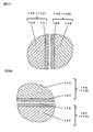
- FIG. 2A is an enlarged view showing a part A of FIG.
- FIG. 2B is an enlarged view showing a part B of FIG.
- FIG. 5A is a time-series change curve diagram of the input of the refrigerant compressor of FIG.
- FIG. 5B is a time-series change curve diagram of the COP of the refrigerant compressor of FIG. 1.
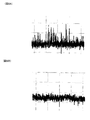
- FIG. 6A shows the surface roughness of the first sliding member before the operation of the refrigerant compressor of FIG.
- FIG. 6B shows the surface roughness of the first sliding member after operation of the refrigerant compressor of FIG.
- It is sectional drawing which shows roughly the refrigerant compressor which concerns on Embodiment 3 of this invention.
- FIG. 12A is a time-series change curve diagram of the input of the refrigerant compressor of FIG. 12B is a time-series change curve diagram of COP of the refrigerant compressor of FIG. It is a figure which shows roughly the freezing apparatus which concerns on Embodiment 4 of this invention. It is sectional drawing which shows the conventional refrigerant compressor schematically.
- the refrigerant compressor includes an electric element, a compression element that is driven by the electric element, compresses the refrigerant, and has a pair of sliding members that move relative to each other, and the electric element
- An airtight container containing the element and the compression element, and a soft film is provided on the sliding surface of one of the sliding members of the pair of sliding members, and the sliding surface of the other sliding member
- a hard film having a hardness higher than that of the soft film is provided.
- the wear resistance of the sliding member can be improved by the hard film.
- the soft coating is slightly worn by local contact by a large number of minute protrusions on the sliding surface, so that friction can be reduced at an early stage and initial conformability can be improved. For this reason, the refrigerant compressor which aimed at reduction of an efficiency fall can be provided.
- the soft film has a hardness lower than the hardness of the base material of the one sliding member that is coated, Hardness higher than the hardness of the base material of one said sliding member may be sufficient. Thereby, the wear resistance and initial conformability of the sliding member can be improved.
- the soft film in the refrigerant compressor according to the third aspect, may contain a phosphate or a resin as a main component. Such a soft film can improve initial conformability.
- a refrigerant compressor includes an electric element, a compression element that is driven by the electric element, compresses the refrigerant, and has a pair of sliding members that move relative to each other, and the electric element
- An airtight container containing the element and the compression element, and the sliding surface of one of the sliding members of the pair of sliding members is equal to or more than the hardness of the sliding surface of the other sliding member
- a soft film having a hardness lower than the hardness of the sliding surface of the other sliding member and covering the hard film.
- the wear resistance of the sliding member can be improved by the hard film.
- the soft coating is slightly worn by local contact by a large number of minute protrusions on the sliding surface, so that friction can be reduced at an early stage and initial conformability can be improved. For this reason, the refrigerant compressor which aimed at reduction of an efficiency fall can be provided.
- the soft film may contain a resin as a main component. Such a soft film can improve initial conformability.
- the resin in the third or fifth aspect, may contain a solid lubricant.
- the solid lubricant reduces the friction coefficient, so that friction and wear can be reduced.
- the hard coating may contain iron oxide as a main component. Such a hard coating can improve the wear resistance of the sliding member.
- a refrigerant compressor according to an eighth aspect is the refrigerant compressor according to any one of the first to seventh aspects, wherein the compression element has a main shaft that is rotated by the electric element and a main bearing that rotatably supports the main shaft.
- the pair of sliding members may be constituted by the main shaft and the main bearing. Even between such a main shaft and main bearing, wear resistance and initial conformability can be improved.
- a refrigerant compressor according to a ninth aspect is the refrigerant compressor according to any one of the first to eighth aspects, wherein the compression element has a cylinder bore having an internal space, and a piston that is reciprocally inserted into the cylinder bore,
- the pair of sliding members may be constituted by the cylinder bore and the piston. Also between such a cylinder bore and a piston, wear resistance and initial conformability can be improved.
- a refrigerant compressor according to a tenth aspect is the refrigerant compressor according to any one of the first to ninth aspects, wherein the electric element is configured to be inverter-driven at a plurality of operation frequencies including an operation frequency smaller than a commercial power supply frequency. Also good. Even during such low-speed operation at an operation frequency smaller than the commercial power supply frequency, the wear resistance and the initial conformability can be improved.
- the refrigeration apparatus includes a radiator, a decompression device, a heat absorber, and the refrigerant compressor according to any one of the first to tenth aspects.
- the refrigerant compressor 100 includes a sealed container 101 as shown in FIG.
- the sealed container 101 is filled with R600a as a refrigerant gas, and lubricating oil 102 is stored at the bottom of the sealed container 101.
- a refrigeration oil such as VG8 or lower low-viscosity mineral oil or ester oil is used, and VG5 or lower refrigeration oil is preferably used.
- the sealed container 101 accommodates the electric element 105 and the compression element 106.
- the electric element 105 includes a stator 103 and a rotor 104 that rotates with respect to the stator 103.
- the compression element 106 is driven by the electric element 105 to compress the refrigerant.
- the compression element 106 is a reciprocating mechanism and includes a crankshaft 107, a cylinder block 111, and a piston 115.
- the crankshaft 107 has a main shaft 108 and an eccentric shaft 109.
- the main shaft 108 is a cylindrical shaft component, and the rotor 104 is press-fitted and fixed to the lower portion, and an oil supply pump 110 communicating with the lubricating oil 102 is provided at the lower end.
- the eccentric shaft 109 is a cylindrical shaft component and is arranged eccentrically with respect to the main shaft 108.
- the cylinder block 111 is made of, for example, an iron-based material such as cast iron, and has a cylinder bore 112 and a main bearing 114.
- the main bearing 114 is a cylindrical bearing component, and is a journal bearing that supports the radial load of the main shaft 108 by rotatably supporting the main shaft 108 by an inner peripheral surface. For this reason, the inner peripheral surface of the main bearing 114 and the outer peripheral surface of the main shaft 108 face each other, and the main shaft 108 slides with respect to the main bearing 114.
- the portions that slide on the inner peripheral surface of the main bearing 114 and the outer peripheral surface of the main shaft 108 are sliding surfaces, and the main bearing 114 and the main shaft 108 having the sliding surfaces constitute a pair of sliding members. To do.
- the cylinder bore 112 has a cylindrical shape, has an internal space, and has an end surface sealed with a valve plate 118.
- One end of the piston 115 is inserted into the internal space of the cylinder bore 112 so as to be reciprocally movable by the rotation of the main shaft 108.
- a compression chamber 113 surrounded by the cylinder bore 112, the valve plate 118, and the piston 115 is formed.
- the inner peripheral surface of the cylinder bore 112 and the outer peripheral surface of the piston 115 face each other, and the piston 115 slides relative to the cylinder bore 112.
- the portions that slide on the inner peripheral surface of the cylinder bore 112 and the outer peripheral surface of the piston 115 are sliding surfaces, and the cylinder bore 112 and the piston 115 having the sliding surfaces constitute a pair of sliding members.
- the other end of the piston 115 is connected to the eccentric shaft 109 via a piston pin 116 and a connecting rod (connecting means) 117.
- the eccentric bearing 120 is a cylindrical bearing part, and is a journal bearing that supports a radial load of the eccentric shaft 109 by supporting a cylindrical eccentric shaft 109 by an inner peripheral surface. For this reason, the inner peripheral surface of the eccentric bearing 120 and the outer peripheral surface of the eccentric shaft 109 face each other, and the eccentric shaft 109 slides with respect to the inner peripheral surface of the eccentric bearing 120.
- the portions that slide on the inner peripheral surface of the eccentric bearing 120 and the outer peripheral surface of the eccentric shaft 109 are sliding surfaces, and the eccentric bearing 120 and the eccentric shaft 109 having the sliding surfaces are a pair of sliding members. Configure.
- the cylinder head 119 is fixed to the side opposite to the cylinder bore 112 side of the valve plate 118, and forms a high-pressure chamber (not shown) by covering the discharge hole of the valve plate 118.
- the suction tube (not shown) and the discharge tube 122 are fixed to the sealed container 101.
- the suction tube is connected to the low pressure side (not shown) of the refrigeration cycle, and guides the refrigerant gas from the refrigeration cycle into the sealed container 101.
- the discharge tube 122 is connected to the high pressure side (not shown) of the refrigeration cycle, and guides the refrigerant gas from the high pressure chamber (not shown) to the refrigeration cycle.
- the suction muffler 121 is sandwiched between the valve plate 118 and the cylinder head 119.
- the main bearing 114 which is one of the pair of sliding members is referred to as a first sliding member 135.
- the main shaft 108 which is the other sliding member is referred to as a second sliding member 136.
- the main bearing 114 is composed of a base material 140 and a soft coating 141 that covers the surface of the base material 140.
- the base material 140 is formed of an iron-based material such as gray cast iron
- the soft film 141 is formed of a film containing phosphate as a main component (phosphate film).
- the soft film 141 is provided on the sliding surface of the main bearing 114 and has a hardness lower than the hardness of the base material 140.
- the main shaft 108 includes a base material 142 and a hard coating 143 that covers the surface of the base material 142.
- the base material 140 is formed of an iron-based material such as gray cast iron
- the hard film 143 is formed of a film (oxide film) containing iron oxide as a main component such as an oxide film.
- the hard coating 143 is provided on the sliding surface of the main shaft 108 and has a hardness higher than the hardness of the opposing soft coating 141 and the hardness of the substrate 140 covered with the soft coating 141.
- the cylinder bore 112 that is one of the pair of sliding members is referred to as a first sliding member 137.
- the piston 115 which is the other sliding member is referred to as a second sliding member 138.
- the cylinder bore 112 is composed of a base material 144 and a soft film 145 that covers the surface of the base material 144.
- the base material 144 is formed of an iron-based material such as gray cast iron, and the soft coating 145 is formed of a phosphate coating.
- the soft coating 145 is provided on the sliding surface of the cylinder bore 112 and has a hardness lower than that of the base material 144.
- the piston 115 includes a base 146 and a hard coating 147 that covers the surface of the base 146.
- the base material 140 is formed of an iron-based sintered material
- the hard film 147 is formed of a film (oxide film) containing iron oxide as a main component such as an oxide film.
- the hard coating 147 is provided on the sliding surface of the piston 115 and has a hardness higher than the hardness of the opposing soft coating 145 and the hardness of the substrate 144 covered with the soft coating 145.
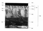
- the oxide film 160 shown in FIG. 3 is used for the hard films 143 and 147.
- the oxide film 160 has a first portion 151, a second portion 152, and a third portion 153, and these portions are laminated in this order from the surface side to the base material 140 side.
- the oxide film 160 has a vertical dimension (film thickness) of about 3 ⁇ m.
- a protective film (resin film 161) for protecting the observation sample is formed on the first portion 151.
- a direction parallel to the surface of the oxide film 160 is referred to as a horizontal direction
- a direction orthogonal to the surface of the oxide film 160 is referred to as a vertical direction.
- the first portion 151 constitutes the surface of the oxide film 160, is formed on the second portion 152, and is formed of a microcrystalline structure.
- the first portion 151 is composed of ferric trioxide (Fe 2 O 3 ) as the most occupying component. It also contained silicon (Si) compounds.
- the first portion 151 includes two portions (a first a portion 151a and a first b portion 151b) having different crystal densities.
- the first a portion 151 a is formed on the first b portion 151 b and constitutes the surface of the oxide film 160.
- the crystal density of the first a portion 151a is smaller than the crystal density of the first b portion 151b.
- the first a portion 151a contains a void portion 158 (a portion that looks black in FIG. 3) and a needle-like tissue 159 in some places.
- the acicular tissue 159 is vertically long, for example, the length on the minor axis side in the horizontal direction is 100 nm or less, and the ratio (aspect ratio) obtained by dividing the vertical diameter by the horizontal diameter is 1 or more. 10 or less.
- the first b portion 151b is a structure in which microcrystals 155 having a particle diameter of 100 nm or less are spread. In the first b portion 151b, there are hardly any voids 158 and needle-like structures 159 as seen in the first a portion 151a.
- the second portion 152 is formed on the third portion 153 and contains a number of vertically long columnar structures 156 arranged in the same direction.
- the columnar structure 156 has a vertical diameter of about 100 nm to 1 ⁇ m, a horizontal diameter of about 100 nm to 150 nm, and an aspect ratio of about 3 to 10.
- the second portion 152 is composed of triiron tetroxide (Fe 3 O 4 ), and also contains a silicon (Si) compound.
- the third portion 153 is formed on the base material 140 and contains a horizontally long lamellar structure 157.
- the lamellar structure 157 has a vertical diameter of several tens of nm or less, a horizontal diameter of about several hundred nm, and an aspect ratio of 0.01 or more and 0.1 or less, which is long in the horizontal direction.
- the third portion 153 is composed of triiron tetroxide (Fe 3 O 4 ), and includes a silicon (Si) compound and a silicon (Si) solid solution portion. It is out.
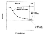
- FIG. 4 is a graph showing the hardness in the depth direction of the main shaft 108 and the base material 140 of the main bearing 114.
- the hardness is indicated by Vickers hardness.
- a nanoindentation device titanium dioxide manufactured by Sienta Omicron Co., Ltd. was used. Further, the soft film 141 of the main bearing 114 could not be measured by this Vickers hardness measurement method.
- a step was performed in which the indenter was pushed into the surface of the main shaft 108 and the load was applied for a certain period of time.
- the next step once the load is unloaded, the indenter is pushed into the surface of the main shaft 108 with a load higher than the load in the step before unloading, and the state where the load is loaded again is maintained for a certain period of time. did.
- the step of increasing the load stepwise was repeated 15 times.
- the load of each step was set so that the maximum load would be 1N.
- the hardness and depth of the oxide film 160 of the main shaft 108 and the base material 142 were measured after each step.
- the hardness of the base material 142 of the main shaft 108 was equivalent to the hardness of the base material 140 of the main bearing 114 which is this mating sliding member. Moreover, the hardness of the oxide film 160 (hard film 143) of the main shaft 108 was equal to or higher than the hardness of the base material 140 of the main bearing 114 which is the counterpart sliding member.
- Such hardness is one of the mechanical properties at or near the surface of an object such as a substance or material, and it is difficult to deform and damage the object when an external force is applied to the object. is there.
- the indentation hardness test method for example, the nanoindentation method mentioned above, the Vickers or Rockwell hardness method, etc. is used for the measurement.
- a wear test such as a ring-on-disk method is used.
- the phosphate coating wears more easily than gray cast iron.
- the phosphate coating constitutes soft coatings 141 and 145, and gray cast iron constitutes the base materials 140 and 144 of the first sliding members 135 and 137. Therefore, the hardness of the soft films 141 and 145 is lower than the hardness of the base materials 140 and 144.
- Electric power supplied from a commercial power supply (not shown) is supplied to the electric element 105 via an external inverter drive circuit (not shown).
- the electric element 105 is inverter-driven at a plurality of operating frequencies, and the rotor 104 of the electric element 105 rotates the crankshaft 107.
- This operating frequency includes a rotational speed smaller than the frequency of the commercial power source.
- the eccentric motion of the eccentric shaft 109 of the crankshaft 107 is converted into a linear motion of the piston 115 by the connecting rod 117 and the piston pin 116, and the piston 115 reciprocates in the compression chamber 113 in the cylinder bore 112. For this reason, the refrigerant gas introduced into the sealed container 101 through the suction tube is sucked into the compression chamber 113 from the suction muffler 121, and further, the refrigerant gas is compressed in the compression chamber 113 and discharged via the cylinder head 119.
- the tube 122 discharges from the sealed container 101.
- the load for compressing the refrigerant gas is transmitted to the eccentric shaft 109 of the crankshaft 107 through the piston 115, the piston pin 116, and the connecting rod 117.
- the load acts on the main shaft 108 from the eccentric shaft 109.
- the refrigerant compressor 100 has a cantilever bearing configuration in which the main bearing 114 supports the compression load acting on the piston 115 via the main shaft 108 disposed below the piston 115.
- the lubricating oil 102 is supplied to each sliding portion from the oil supply pump 110.
- the lubricating oil 102 lubricates each sliding portion and reduces leakage of the refrigerant gas from the compression chamber 113 by sealing between the piston 115 and the cylinder bore 112.
- the lubricating oil 102 having a lower viscosity than that of the conventional one is used or the sliding area of each sliding part is reduced for higher efficiency.
- the sliding condition becomes more severe, and the oil film becomes thinner and the oil film is easily cut between the sliding portions.
- the soft films 141 and 145 are provided on the sliding surfaces of the first sliding members 135 and 137, and the hard films 143 and 147 are provided on the sliding surfaces of the second sliding members 136 and 138.
- the hard films 143 and 147 are provided on the sliding surfaces of the second sliding members 136 and 138.
- FIG. 5A shows a time series change of the input to the refrigerant compressor 100
- FIG. 5B shows a time series change of the COP of the refrigerant compressor 100.
- FIG. Here, the performance evaluation of the refrigerant compressor 100 was performed at low speed operation (rotation frequency: 17 Hz) by inverter driving.
- COP Coefficient of Performance
- W refrigeration capacity
- W input
- a refrigerant compressor in which one sliding member of the pair of sliding members is provided with a hard film and the other sliding member is not provided with a film is used.
- both the refrigerant compressor 100 of the present embodiment and the conventional refrigerant compressor had the highest input immediately after the start of operation (hereinafter referred to as initial input). Thereafter, the input gradually decreased with the passage of the operation time, and finally showed a constant value (hereinafter referred to as a steady input) having almost no change.
- the refrigerant compressor 100 had a lower initial input than the conventional refrigerant compressor, and the transition time from the initial input to the steady input was shorter than that of the conventional refrigerant compressor.
- the transition time of the refrigerant compressor 100 is t1
- the transition time of the conventional refrigerant compressor is t2
- t1 is about 1 ⁇ 2 of t2.
- the COP of the refrigerant compressor 100 is stable in a shorter time than the conventional refrigerant compressor, and has an absolute value higher than that of the conventional refrigerant compressor.
- the cause of the improvement in the COP of the refrigerant compressor 100 is that the phosphate coatings of the soft coatings 141 and 145 cover the unevenness of the surfaces of the first sliding members 135 and 137. Thereby, it is estimated that the oil film thinning and the oil film breakage between the first sliding members 135 and 137 and the second sliding members 136 and 138 are reduced. Therefore, the surface roughness of the sliding member was analyzed.
- FIG. 6A shows the surface roughness of the first sliding member 135 before the operation of the refrigerant compressor 100
- FIG. 6B shows the surface roughness of the first sliding member 135 after the operation of the refrigerant compressor 100. Yes.
- the operation of the refrigerant compressor 100 eliminates the protrusion of the first sliding member 135, and the surface of the first sliding member 135 is smoothed.
- the phosphate film of the soft film 141 that is softer than the base member 140 of the sliding member is worn by self-sacrificing due to the protrusion of the oxide film 160 of the hard film 143.
- the wear resistance of the hard film 143 is improved by using a combination of the hard film 143 and the soft film 141.
- the main shaft 108 when a compressive load is applied, the main shaft 108 is inclined in the main bearing 114 and the oil film tends to be thin at the upper and lower ends of the main bearing 114. Furthermore, the oil film tends to become extremely thin during operation at a very low rotational speed. Even in such a case, the initial running-in effect that prevents the increase in friction can be obtained by the self-sacrificing wear of the soft coating 141, so that the operation efficiency of the refrigerant compressor 100 is improved.
- the oxide film 160 has a first portion 151 that constitutes a surface thereof containing ferric trioxide (Fe 2 O 3 ) as a main component. Since this ferric trioxide (Fe 2 O 3 ) has a microcrystalline structure, the surface of the oxide film 160 has a minute uneven shape. Therefore, the lubricating oil 102 accumulates on the uneven portions, and an oil film is easily formed on the surface of the oxide film 160. Therefore, the oxide film 160 can improve the conformability of the sliding surface at the initial stage of sliding.
- ferric trioxide Fe 2 O 3
- the microcrystalline structure constituting the first portion 151 has a few voids 158 in some places, or fine irregularities are generated on the surface by the microcrystal.
- the lubricating oil 102 is likely to be held on the surface (sliding surface) of the oxide film 160 by the capillary phenomenon due to such a small gap 158 and / or minute unevenness. For this reason, even when the sliding state is severe, the lubricating oil 102 can be fastened to the sliding surface to exhibit “oil retention”, and an oil film is easily formed on the sliding surface.
- the oxide film 160 can exhibit “oil retention” while having high wear resistance. For this reason, even in the initial stage of sliding, an oil film can remain between the sliding members, and wear resistance can be maintained. Further, this, combined with the initial running-in effect due to the self-sacrificing wear of the soft coating 141, enables high-efficiency operation with low input from the initial operation.
- the oxide film 160 is an iron oxide, it is chemically more stable than the phosphate film and has a hardness higher than that of the phosphate film. And the 1st part 151 which comprises the surface of the oxide film 160 contains the silicon (Si) compound whose hardness is higher than the oxide of iron. For this reason, the oxide film 160 can exhibit higher wear resistance.
- the second portion 152 and the third portion 153 of the oxide film 160 both contain a silicon (Si) compound and are interposed between the first portion 151 and the base material 154. Therefore, the adhesion force of the oxide film 160 to the base material 154 is strong.
- the third portion 153 has a higher silicon content than the second portion 152. As described above, the portion containing the silicon (Si) compound is laminated, and the content of silicon in the third portion 153 in contact with the base material 154 is large, so that the adhesion of the oxide film 160 to the base material 154 is stronger. is there. As a result, the proof stress of the oxide film 160 is improved with respect to a load during sliding, and the wear resistance of the oxide film 160 is further increased. Therefore, even if the first portion 151 is worn, the second portion 152 and the third portion 153 can exhibit more excellent wear resistance.
- the soft coatings 141 and 145 are provided on the sliding surfaces of the main bearing 114 and the cylinder bore 112, and the hard coatings 143 and 147 are provided on the sliding surfaces of the main shaft 108 and the piston 115.
- the locations where the soft coating and the hard coating are provided are not limited thereto.
- a soft coating may be provided on the sliding surface of the main shaft 108, and a hard coating may be provided on the sliding surface of the main bearing 114. Further, a soft film may be provided on the sliding surface of the piston 115 and a hard film may be provided on the sliding surface of the cylinder bore 112.
- an eccentric shaft 109 and a bearing (eccentric bearing) of the eccentric shaft 109 in the connecting rod 117 may be provided, and a soft film may be provided on one of them and a hard film may be provided on the other.
- the crankshaft 107 and the thrust surface of the cylinder block 111 that supports the load of the crankshaft 107 in the axial direction are provided, and a soft film is provided on one side and a hard film is provided on the other side. May be. Even the sliding portion of the thrust surface where the oil film pressure is difficult to generate can achieve the effect of improving the wear resistance and improving the efficiency.
- a soft film and a hard film may be provided on all of them, or a soft film and a hard film may be provided on some of them. It may be provided.
- a hard coating or a soft coating was provided directly on the base material of the sliding member.
- another film layer may be provided between the base material of the sliding member and the hard film or the soft film.
- the oxide film 160 is used as the hard film, but the hard film is not limited to this as long as it has a hardness higher than that of the soft film.
- the hard coating include a compound layer, a mechanical strength improving layer, and a layer formed by a coating method.
- the hard film is formed by a general quenching method and a method in which carbon or nitrogen is immersed in the surface layer. It may be.
- the hard film may be a film formed by an oxidation treatment with water vapor and an oxidation treatment immersed in an aqueous solution of sodium hydroxide.
- the hard film is formed by cold working, work hardening, solid solution strengthening, precipitation strengthening, dispersion strengthening and crystal grain refinement, and is a layer (mechanical layer) that suppresses dislocation slip motion and strengthens the substrate. Strength improving layer).
- the hard film may be a layer formed by a coating method such as plating, thermal spraying, PVD, CVD, or DLC.
- the phosphate film is used as the soft film, but the present invention is not limited to this.
- a film containing a resin as a main component may be used, and the resin may contain a solid lubricant.
- a solid lubricant in the resin film, it is possible to reduce the coefficient of friction of the portion where solid contact has occurred and to further reduce the sliding loss.
- membranes, such as zinc plating and tin plating as a soft film.
- the reciprocating (reciprocating) refrigerant compressor 100 is illustrated, but the refrigerant compressor may be of other types such as a rotary type, a scroll type, and a vibration type.
- the configuration in which the soft coating and the hard coating are provided on the sliding surfaces of the pair of sliding members is not limited to the refrigerant compressor, and is similarly used in an apparatus having the sliding surfaces. Is obtained.
- a pump and a motor may be used as a device having this sliding surface.
- FIG. 7 shows a refrigeration apparatus in Embodiment 2 of the present invention.
- This refrigeration apparatus includes the refrigerant compressor 100 according to Embodiment 1 as the refrigerant compressor 200.
- the refrigeration apparatus includes a main body 201, a partition wall 207, and a refrigerant circuit 209.
- the main body 201 has a heat-insulating box with one surface opened and a door that opens and closes the opening.
- the partition wall 207 partitions the inside of the main body 201 into an article storage space 203 and a machine room 205.
- the refrigerant circuit 209 has a configuration in which the refrigerant compressor 100, the radiator 213, the decompression device 215, and the heat absorber 217 are connected in a ring shape, and cools the inside of the storage space 203.
- the heat absorber 217 is disposed in the storage space 203 provided with a blower (not shown). The cooling heat of the heat absorber 217 is agitated so as to circulate in the storage space 203 by the blower, as indicated by an arrow, and cools the storage space 203.
- the refrigeration apparatus having the above configuration includes the refrigerant compressor 100 according to Embodiment 1 of the present invention as the refrigerant compressor 200.
- the soft film is provided on the sliding surface of one sliding member of the pair of sliding members, and the hard film is provided on the sliding surface of the other sliding member.
- the reduction of the operating efficiency of the refrigerant compressor 200 is aimed at by the improvement of the abrasion resistance of the sliding part by a hard film, and the improvement of the initial conformability by a soft film. Therefore, a refrigeration apparatus including such a refrigerant compressor 200 can reduce power consumption, achieve energy saving, and improve reliability.
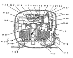
- the refrigerant compressor 1100 according to Embodiment 3 includes a sealed container 1101.
- the sealed container 1101 is filled with R600a as the refrigerant gas 1102, and mineral oil is stored as lubricating oil 1103 at the bottom of the sealed container 1101.
- the sealed container 1101 accommodates the electric element 1106 and the compression element 1107.
- the electric element 1106 includes a stator 1104 and a rotor 1105 that rotates with respect to the stator 1104.
- the compression element 1107 is driven by the electric element 1106 to compress the refrigerant.
- the compression element 1107 is a reciprocating mechanism and includes a crankshaft 1108, a cylinder block 1112, and a piston 1132.
- the crankshaft 1108 has a main shaft 1109 and an eccentric shaft 1110, and the base material is formed of an iron-based material such as gray cast iron.
- the main shaft 1109 is a cylindrical shaft component, the lower portion is press-fitted and fixed to the rotor 1105, and an oil supply pump 1120 communicating with the lubricating oil 1103 is provided at the lower end.
- the eccentric shaft 1110 is a cylindrical shaft component and is arranged eccentrically with respect to the main shaft 1109.
- the cylinder block 1112 is made of an iron-based material such as cast iron, for example, and has a cylinder bore 1113 and a main bearing 1111.
- the cylinder bore 1113 is integrally formed with the main bearing 1111, has a cylindrical shape, has an internal space, and has an end surface sealed with a valve plate 1139.
- the main bearing 1111 is a cylindrical bearing component, and is a journal bearing that rotatably supports the main shaft 1109 by an inner peripheral surface and supports a radial load of the main shaft 1109. For this reason, the inner peripheral surface of the main bearing 1111 and the outer peripheral surface of the main shaft 1109 face each other, and the main shaft 1109 slides with respect to the inner peripheral surface of the main bearing 1111. As described above, the portions that slide on the inner peripheral surface of the main bearing 1111 and the outer peripheral surface of the main shaft 1109 are sliding surfaces, and the main bearing 1111 and the main shaft 1109 having the sliding surfaces constitute a pair of sliding members. To do.
- One end of the piston 1132 is inserted into the internal space of the cylinder bore 1113 so as to be reciprocally movable by the rotation of the main shaft 1109. Thereby, a compression chamber 1134 surrounded by the cylinder bore 1113, the valve plate 1139, and the piston 1132 is formed.
- the inner peripheral surface of the cylinder bore 1113 and the outer peripheral surface of the piston 1132 face each other, and the piston 1132 slides relative to the cylinder bore 1113.
- the portions that slide on the inner peripheral surface of the cylinder bore 1113 and the outer peripheral surface of the piston 1132 are sliding surfaces, and the cylinder bore 1113 and the piston 1132 having the sliding surfaces constitute a pair of sliding members.
- a piston pin hole 1116 is provided at the other end of the piston 1132.
- the piston pin 1115 has a substantially cylindrical shape, is disposed in parallel with the eccentric shaft 1110, and is locked to the piston pin hole 1116 so as not to rotate.
- the connecting rod (connecting means) 1117 is made of an aluminum cast product, and is provided with an eccentric bearing 1119 at one end, and the piston 1132 is connected to the other end via a piston pin 1115. Accordingly, the connecting rod 1117 connects the eccentric shaft 1110 and the piston 1132 supported by the eccentric bearing 1119.
- the eccentric bearing 1119 is a cylindrical bearing component, and supports a radial load of the eccentric shaft 1110 by supporting a cylindrical eccentric shaft 1110 by an inner peripheral surface. For this reason, the inner peripheral surface of the eccentric bearing 1119 and the outer peripheral surface of the eccentric shaft 1110 face each other, and the eccentric shaft 1110 slides on the inner peripheral surface of the eccentric bearing 1119.
- the portions that slide on the inner peripheral surface of the eccentric bearing 1119 and the outer peripheral surface of the eccentric shaft 1110 are sliding surfaces, and the eccentric bearing 1119 and the eccentric shaft 1110 having this sliding surface are a pair of sliding members.
- the cylinder head 1140 is fixed to the side opposite to the cylinder bore 1113 side of the valve plate 1139, and forms a high-pressure chamber (not shown) by covering the discharge hole of the valve plate 1139.
- a suction tube (not shown) is fixed to the sealed container 1101 and connected to the low pressure side (not shown) of the refrigeration cycle, and guides the refrigerant gas 1102 from the refrigeration cycle into the sealed container 1101. Further, the suction muffler 1142 is sandwiched between the valve plate 1139 and the cylinder head 1140.
- the sliding surface of the main shaft 1109 of the crankshaft 1108 is composed of a base material 1150 and a film that covers the surface of the base material 1150.
- the base material 1150 is formed of an iron-based material such as gray cast iron (FC cast iron).
- the film is composed of a hard film such as an oxide film 1160 that covers the base material 1150 and a soft film such as a resin film 1170 that covers the hard film.
- the hard coating has a hardness equal to or greater than the hardness of the sliding surface of the opposing main bearing 1111 and is formed of a coating containing iron oxide as a main component (oxide coating 1160).
- the soft coating covers part or all of the hard coating and has a hardness smaller than the hardness of the sliding surface of the opposing main bearing 1111.
- the soft film is formed of a film containing a resin as a main component (resin film 1170) or the like, and the resin may contain a solid lubricant.
- the resin film 1170 contains, for example, polyamideimide (PAI) as a binder and molybdenum disulfide (MoS2) particles (not shown) as a solid lubricant.
- PAI polyamideimide
- MoS2 molybdenum disulfide
- the binder of the resin film 1170 is not limited to polyamideimide.
- a thermosetting resin that is excellent in oil resistance, heat resistance, refrigerant resistance, and organic agent resistance is used.
- examples of such a binder include an epoxy resin and a phenol resin.
- the solid lubricant contained in the resin film 1170 is not limited to molybdenum disulfide.
- a solid lubricant tetrafluoroethylene resin (PTFE) and graphite (C), or a mixture thereof is used.
- antimony trioxide Sb 2 O 3
- antimony trioxide captures the air and oxygen that have entered the resin film 1170 and is oxidized first. For this reason, the deterioration by the oxidation of the solid lubricant in the resin film 1170 can be suppressed, and the wear suppression effect by the solid lubricant can be maintained.
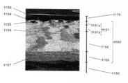
- the oxide film 1160 has a vertical dimension (film thickness) of about 3 ⁇ m.
- a protective film (resin film) for protecting the observation sample is formed on the resin film 1170.
- a direction parallel to the surface of the oxide film 1160 is referred to as a horizontal direction, and a direction orthogonal to the surface of the oxide film 1160 is referred to as a vertical direction.
- the oxide film 1160 has a first portion 1151, a second portion 1152, and a third portion 1153, and these portions are laminated in this order from the surface side to the substrate 1150 side.
- the first portion 1151 constitutes the surface of the oxide film 1160, is formed on the second portion 1152, and is formed of a microcrystalline structure.
- the first portion 1151 is composed of most ferric trioxide (Fe 2 O 3 ). It also contained silicon (Si) compounds.
- the first portion 1151 includes two portions (a first a portion 1151a and a first b portion 1151b) having different crystal densities.
- the first a portion 1151a is formed on the first b portion 1151b and constitutes the surface of the oxide film 1160.
- the crystal density of the first a portion 1151a is smaller than the crystal density of the first b portion 1151b.
- the first a portion 1151a contains a void portion 1158 (a portion that looks black in FIG. 10) and a needle-like tissue 1159 in some places.
- the acicular tissue 1159 is vertically long, for example, the length on the minor axis side in the horizontal direction is 100 nm or less, and the ratio (aspect ratio) obtained by dividing the diameter in the vertical direction by the diameter in the horizontal direction is 1 or more. 10 or less.
- the first b portion 1151b is a structure in which microcrystals 155 having a particle diameter of 100 nm or less are spread. In the first b portion 1151b, there are hardly any voids 1158 and needle-like structures 1159 as seen in the first a portion 1151a.
- the second portion 1152 is formed on the third portion 1153 and contains a number of vertically long columnar structures 1156 arranged in the same direction.
- the columnar texture 1156 has a vertical diameter of about 100 nm to 1 ⁇ m, a horizontal diameter of about 100 nm to 150 nm, and an aspect ratio of about 3 to 10.
- the second portion 1152 is composed of triiron tetroxide (Fe 3 O 4 ), and also contains a silicon (Si) compound.
- the third portion 1153 is formed on the base material 1150 and contains a horizontally long lamellar structure 1157.
- the lamellar structure 1157 has a vertical diameter of several tens of nm or less, a horizontal diameter of about several hundred nm, and an aspect ratio of 0.01 or more and 0.1 or less, which is long in the horizontal direction.
- the third portion 1153 is composed of triiron tetroxide (Fe 3 O 4 ), and includes a silicon (Si) compound and a silicon (Si) solid solution portion. It is out.
- the oxide film 1160 includes a first portion 1151, a second portion 1152, and a third portion 1153, which are stacked in this order.
- the structure and stacking order of the oxide film 1160 are not limited to this.
- the oxide film 1160 may be composed of a single layer of the first portion 1151.
- the oxide film 1160 may be constituted by two layers of the first part 1151 and the second part 1152 so that the first part 1151 forms the surface of the oxide film 1160.
- the oxide film 1160 may be constituted by two layers of the first part 1151 and the third part 1153 so that the first part 1151 forms the surface of the oxide film 1160.
- the oxide film 1160 may contain a composition other than the first portion 1151, the second portion 1152, and the third portion 1153.
- the oxide film 1160 is constituted by four layers of the first part 1151, the second part 1152, the first part 1151, and the third part 1153 so that the first part 1151 forms the surface of the oxide film 1160. May be.
- Such a structure and stacking order of the oxide film 1160 can be easily realized by adjusting various conditions.
- Typical conditions include a manufacturing method (forming method) of the oxide film 1160.
- a known method for oxidizing an iron-based material can be suitably used as a method for manufacturing the oxide film 1160, but is not limited thereto.
- Conditions in the manufacturing method are appropriately set according to conditions such as the type of the iron-based material forming the base material 1150, the surface state of the base material 1150 (polishing finish, etc.), the physical properties of the desired oxide film 1160, and the like.
- the oxide film 1160 is a mouse 1150 within a range of several hundred degrees C. (for example, 400 to 800 degrees C.) using a known oxidizing gas such as carbon dioxide (carbon dioxide gas) and a known oxidation facility. It is formed by oxidizing cast iron.
- a known oxidizing gas such as carbon dioxide (carbon dioxide gas) and a known oxidation facility. It is formed by oxidizing cast iron.
- a coating agent blended with the material of the resin film 1170 is applied to the crankshaft 1108 by spraying.
- a masking jig having an appropriate shape is attached in order to prevent the coating agent from adhering to an unnecessary place during application.
- a horse hair buff is more preferable than a nylon buff containing abrasive grains and a relatively hard steel buff.
- baking is performed at a temperature of 200 ° C. or higher and 250 ° C. or lower for about 30 minutes to 2 hours to evaporate all the diluent in the coating agent. Thereby, the resin film 1170 is completely fixed to the surface of the oxide film 1160.
- FIG. 11 is a graph showing the hardness in the depth direction of the main shaft 1109 and the main bearing 1111. The hardness is indicated by Vickers hardness.
- a nanoindentation device titanium dioxide manufactured by Sienta Omicron Co., Ltd. was used.
- a step was performed in which the indenter was pushed into the surface of the main shaft 1109 to maintain a state in which a load was applied for a certain period of time.
- the next step once the load is unloaded, the indenter is pushed into the surface of the main shaft 1109 with a load higher than the load in the step before unloading, and the state in which the load is loaded again is maintained for a certain period of time. did.
- the step of increasing the load stepwise was repeated 15 times.
- the load of each step was set so that the maximum load would be 1N.
- the hardness and depth of the oxide film 1160 of the main shaft 1109 and the base material 1150 were measured after each step.
- the hardness of the oxide film 1160 of the main shaft 1109 is equal to or higher than the hardness of the main bearing 1111 that is the counterpart sliding member.
- the hardness of the resin film 1170 of the main shaft 1109 is significantly smaller than the hardness of the oxide film 1160 and the base material 1150, it could not be measured with a nanoindentation apparatus. Therefore, the hardness of the resin film 1170 is estimated based on the result of the relative comparison by the wear test, and this hardness is indicated by a dotted line in FIG.
- the abrasion test of the resin film 1170 was performed by a ring-on-disk method.
- the ring used for the test was made of the same material as the main bearing 1111, and the disk was made of the same material as the main shaft 1109.
- the disk surface was provided with a resin film 1170 having a thickness of about 3 ⁇ m and made of PAI resin.
- the ring and disk While the ring and disk are immersed in oil, the ring is rotated at a rotational speed of 1 m / s for 1 hour while a load of 1000 N is applied to the film, and the ring is slid on the film. The state of the sliding surface of the coating and the ring surface is observed. As a result, the wear amount of the ring was almost zero, whereas the resin film 1170 of the disc was worn by about 1 to 2 ⁇ m. From this, it was determined that the hardness of the resin film 1170 is lower than the hardness of the main bearing 1111 in terms of the hardness index.
- Such hardness is one of the mechanical properties at or near the surface of an object such as a substance or material, and it is difficult to deform and damage the object when an external force is applied to the object. is there.
- the indentation hardness test method for example, the nanoindentation method mentioned above, the Vickers or Rockwell hardness method, etc.
- a wear test such as a ring-on-disk method is used for a measurement object that is difficult to measure by an indentation hardness test method, such as a resin film and a film such as a phosphate film.
- Electric power supplied from a commercial power supply (not shown) is supplied to the electric element 1106 via an external inverter drive circuit (not shown). Accordingly, the electric element 1106 is inverter-driven at a plurality of operating frequencies, and the rotor 1105 of the electric element 1106 rotates the crankshaft 1108. This operating frequency includes a rotational speed smaller than the frequency of the commercial power source.
- the eccentric motion of the eccentric shaft 1110 of the crankshaft 1108 is converted into a linear motion of the piston 1132 by the connecting rod 1117 and the piston pin 1115, and the piston 1132 reciprocates in the compression chamber 1134 in the cylinder bore 1113.
- the refrigerant gas introduced into the sealed container 1101 through the suction tube is sucked into the compression chamber 1134 from the suction muffler 1142, and further, the refrigerant gas is compressed in the compression chamber 1134 and discharged from the sealed container 1101.
- the lubricating oil 1103 is supplied from the oil pump 1120 to each sliding surface and lubricates the sliding surface. At the same time, the lubricating oil 1103 forms a seal between the piston 1132 and the cylinder bore 1113 to seal the compression chamber 1134.
- FIG. 12A shows the time series change of the refrigerant compressor input
- FIG. 12B shows the time series change of the coefficient of performance COP (Coefficient of Performance) of the refrigerant compressor.
- COP is a coefficient used as a measure of the energy consumption efficiency of a refrigerant compressor such as a refrigeration apparatus, and is a value obtained by dividing the refrigeration capacity (W) by the input (W).
- W refrigeration capacity
- input and COP were obtained when the refrigerant compressor was operated at a low speed at an operation frequency of 20 Hz.
- the conventional refrigerant compressor is provided with a hard coating on the sliding surface of the main shaft without providing a soft coating.
- the input immediately after the start of operation (hereinafter referred to as initial input) is the highest for both the refrigerant compressor of the present embodiment and the conventional refrigerant compressor.
- the input gradually decreases with the lapse of the subsequent operation time, and finally shows a constant value (hereinafter referred to as a steady input) that hardly changes.
- the refrigerant compressor of the present embodiment has a lower initial input than the conventional refrigerant compressor, and also has a shorter transition time from the initial input to the steady input.
- t1 of the refrigerant compressor of the present embodiment and the transition time t2 of the conventional refrigerant compressor t1 is about 1 ⁇ 2 of t2.
- coolant compressor of this Embodiment is stabilized and improved earlier than the conventional refrigerant
- the sliding surface of main shaft 1109 is covered with oxide film 1160 having a hardness equal to or higher than the hardness of main bearing 1111 and oxide film 1160, and A resin film 1170 having a hardness smaller than that of the bearing 1111 is provided.
- oxide film 1160 having a hardness equal to or higher than the hardness of main bearing 1111 and oxide film 1160
- a resin film 1170 having a hardness smaller than that of the bearing 1111 is provided.
- the solid lubricant such as molybdenum disulfide particles contained in the resin film 1170 will slide on the main bearing 1111. Move to the moving surface. Thereby, the coefficient of friction between the main shaft 1109 and the main bearing 1111 can be reduced, and the efficiency of the refrigerant compressor 1100 can be increased.
- the oxide film 1160 is an iron oxide, it is harder and chemically more stable than a conventional phosphate film.
- the first portion 1151 constituting the surface of the oxide film 1160 contains a silicon (Si) compound having a hardness higher than that of iron oxide. Therefore, the oxide film 1160 exhibits high wear resistance.
- the second portion 1152 and the third portion 1153 of the oxide film 1160 both contain a silicon (Si) compound and are located between the first portion 1151 and the substrate 1150. For this reason, the adhesive force with respect to the base material 1150 of the oxide film 1160 becomes strong. Moreover, the third portion 1153 has a higher silicon content than the second portion 1152. In this manner, the second portion 1152 and the third portion 1153 containing a silicon (Si) compound are stacked, and the third portion 1153 having a higher silicon content is in contact with the substrate 1150. Thereby, the adhesion of the oxide film 1160 is further strengthened.
- the proof stress of the oxide film 1160 is improved with respect to the load during sliding, and the wear resistance of the oxide film 1160 is further increased. Even if the first portion 1151 forming the surface of the oxide film 1160 is worn, the second portion 1152 and the third portion 1153 remain, so that the oxide film 1160 exhibits more excellent wear resistance. .
- the first portion 1151 has a microcrystalline structure, and a small gap 1158 is formed between these microcrystals, or minute irregularities are formed on the surface.
- a part of the resin film 1170 enters into the voids 1158 and minute irregularities on the surface, so that the adhesion force of the resin film 1170 to the oxide film 1160 is It will be powerful.
- the hard film and the soft film are provided on the sliding surface of the main shaft 1109, but the sliding surface on which the hard film and the soft film are provided is not limited to this. That is, the sliding surface of one sliding member of the pair of sliding members covers the hard coating having a hardness equal to or higher than the hardness of the sliding surface of the other sliding member, and covers the other It is only necessary to provide a soft film having a hardness lower than the hardness of the sliding surface of the sliding member.
- the sliding surface of the main bearing 1111 has a hardness lower than the hardness of the sliding surface of the main shaft 1109 that covers the hard coating that is equal to or higher than the hardness of the sliding surface of the main shaft 1109.
- a soft film may be provided.
- an eccentric shaft 1110 and an eccentric bearing 1119 may be used as a pair of sliding members, and a hard coating and a soft coating may be provided on one of them.
- a piston 1132 and a cylinder bore 1113 may be used as a pair of sliding members, and a hard coating and a soft coating may be provided on one of them.
- the pair of sliding members the crankshaft 107 and the thrust surface of the cylinder block 111 that supports the load of the crankshaft 107 in the axial direction thereof may be used, and a hard coating and a soft coating may be provided on one of them.
- a soft film and a hard film may be provided on all of them, or a soft film and a hard film may be provided on some of them. It may be provided.
- the oxide film 1160 is used as the hard film of the main shaft 1109, but the hard film is not limited to this as long as it has a hardness equal to or higher than the hardness of the sliding surface of the main bearing 1111.
- examples of the hard film of the main shaft 1109 include a compound layer, a mechanical strength improving layer, and a layer formed by a coating method.
- the hard film may be a film formed by a general quenching method and a method in which carbon or nitrogen is immersed in the surface layer. Further, the hard film may be a film formed by an oxidation treatment with water vapor and an oxidation treatment immersed in an aqueous solution of sodium hydroxide. Further, the hard film is formed by cold working, work hardening, solid solution strengthening, precipitation strengthening, dispersion strengthening and crystal grain refinement, and is a layer (machine) that suppresses the slip movement of dislocations and strengthens the base material 1150. Strength improvement layer). Further, the hard film may be a layer formed by a coating method such as plating, thermal spraying, PVD, or CVD.
- an iron-based material is used for the base material 1150 of the main shaft 1109.
- the base material 1150 may be an iron that can form a film having a hardness higher than that of the main bearing 1111. Materials other than the system can be used.
- the resin film 1170 is used as the soft film, but the present invention is not limited to this as long as the film has a hardness lower than the hardness of the opposed sliding surface.
- a film such as zinc plating or tin plating may be used as the soft film.
- the soft film is a film having a hardness smaller than the hardness of the opposed sliding surface
- the types of components and the number of layers constituting the soft film are not limited thereto.
- the soft film may be composed of a plurality of layers having different components.
- a reciprocating (reciprocating) refrigerant compressor is exemplified, but the refrigerant compressor may be of other types such as a rotary type, a scroll type, and a vibration type.
- the configuration provided with the hard coating and the soft coating having the above-described configuration on the sliding surface is not limited to the refrigerant compressor, and is similarly used in an apparatus having the sliding surface, and the same effect can be obtained thereby. It is done.
- a device having this sliding surface for example, a pump and a motor may be used.
- FIG. 13 is a schematic diagram illustrating a configuration of a refrigeration apparatus according to Embodiment 4. Here, only the outline of the basic configuration of the refrigeration apparatus will be described. Note that this refrigeration apparatus includes the refrigerant compressor 1100 according to Embodiment 3 as the refrigerant compressor 1300.
- the refrigeration apparatus includes a main body 1301, a partition wall 1307, and a refrigerant circuit 1309.
- the main body 1301 is composed of a heat-insulating box whose one surface is open and a door that opens and closes the opening.
- the partition wall 1307 partitions the inside of the main body 1301 into an article storage space 1303 and a machine room 1305.
- the refrigerant circuit 1309 is configured by connecting a refrigerant compressor 1300, a radiator 1313, a pressure reducing device 1315, and a heat absorber 1317 in an annular shape, and cools the storage space 1303.
- the heat absorber 1317 is disposed in a storage space 1303 provided with a blower (not shown). The cooling heat of the heat absorber 1317 is agitated so as to circulate in the storage space 1303 by the blower as indicated by an arrow, thereby cooling the storage space 1303.
- the refrigeration apparatus having the above configuration includes the refrigerant compressor 1100 according to Embodiment 3 as the refrigerant compressor 1300.
- this refrigerant compressor 1300 a hard coating having a hardness equal to or higher than the hardness of the sliding surface of the other sliding member on the sliding surface of one sliding member of the pair of sliding members, and a hard coating And a soft film having a hardness lower than the hardness of the sliding surface of the other sliding member is provided.
- the reduction of the operating efficiency of the refrigerant compressor 1300 is achieved by improving the wear resistance of the sliding portion by the hard film and improving the initial conformability by the soft film. Therefore, a refrigeration apparatus including such a refrigerant compressor 1300 can reduce power consumption, achieve energy saving, and improve reliability.
- the present invention can provide a refrigerant compressor and a refrigeration apparatus including the refrigerant compressor that reduce the reduction in efficiency, and thus can be widely applied to various devices using a refrigeration cycle.
- Refrigerant compressor 101 Sealed container 105: Electric element 106: Compression element 108: Main shaft (sliding member) 109: Eccentric shaft (sliding member) 112: Cylinder bore (sliding member) 114: Main bearing (sliding member) 115: Piston (sliding member) 120: Eccentric bearing (sliding member) 140: base material 141: soft film 142: base material 143: hard film 144: base material 145: soft film 146: base material 147: hard film 154: base material 160: oxide film (hard film) 200: Refrigerant compressor 213: Radiator 215: Pressure reducing device 217: Heat absorber 1100: Refrigerant compressor 1101: Sealed container 1106: Electric element 1107: Compression element 1109: Main shaft (sliding member) 1110: Eccentric shaft (sliding member) 1111: Main bearing (sliding member) 1113: Cylinder bore (sliding member) 1119: Eccentric bearing (sliding member
Landscapes
- Engineering & Computer Science (AREA)
- Mechanical Engineering (AREA)
- General Engineering & Computer Science (AREA)
- Physics & Mathematics (AREA)
- Thermal Sciences (AREA)
- Compressor (AREA)
Abstract
L'invention concerne un compresseur de réfrigérant qui comprend : un élément d'activation électrique ; un élément de compression actionné par l'élément d'activation électrique pour comprimer un réfrigérant et ayant une paire d'éléments coulissants se faisant face et se déplaçant l'un par rapport à l'autre ; et un récipient fermé destiné à contenir l'élément d'activation électrique et l'élément de compression. Un revêtement souple est disposé sur la surface coulissante de l'un des éléments de la paire d'éléments coulissants, et un revêtement dur ayant une dureté supérieure à celle du revêtement souple est disposé sur l'autre élément coulissant.
Applications Claiming Priority (4)
| Application Number | Priority Date | Filing Date | Title |
|---|---|---|---|
| JP2016225647A JP2020012374A (ja) | 2016-11-21 | 2016-11-21 | 冷媒圧縮機およびそれを用いた冷凍装置 |
| JP2016-225647 | 2016-11-21 | ||
| JP2016-226462 | 2016-11-22 | ||
| JP2016226462A JP2020012375A (ja) | 2016-11-22 | 2016-11-22 | 冷媒圧縮機およびそれを用いた冷凍装置 |
Publications (1)
| Publication Number | Publication Date |
|---|---|
| WO2018092854A1 true WO2018092854A1 (fr) | 2018-05-24 |
Family
ID=62145560
Family Applications (1)
| Application Number | Title | Priority Date | Filing Date |
|---|---|---|---|
| PCT/JP2017/041319 Ceased WO2018092854A1 (fr) | 2016-11-21 | 2017-11-16 | Compresseur de réfrigérant et dispositif de réfrigération l'utilisant |
Country Status (1)
| Country | Link |
|---|---|
| WO (1) | WO2018092854A1 (fr) |
Cited By (1)
| Publication number | Priority date | Publication date | Assignee | Title |
|---|---|---|---|---|
| EP3546613A4 (fr) * | 2016-11-28 | 2019-10-02 | Panasonic Intellectual Property Management Co., Ltd. | Film de revêtement d'oxyde formé sur une surface de substrat d'un corps fritté à base de fer, élément coulissant pourvu dudit film de revêtement d'oxyde et dispositif pourvu dudit élément coulissant |
Citations (5)
| Publication number | Priority date | Publication date | Assignee | Title |
|---|---|---|---|---|
| JPH0385389A (ja) * | 1989-08-30 | 1991-04-10 | Toyoda Mach Works Ltd | 多機能ポンプ |
| JPH06264884A (ja) * | 1993-03-12 | 1994-09-20 | Toshiba Corp | コンプレッサ |
| JPH08121361A (ja) * | 1994-10-31 | 1996-05-14 | Hitachi Ltd | スクリュウロータ及びスクリュウ式圧縮機並びにその製法 |
| JP2011021530A (ja) * | 2009-07-15 | 2011-02-03 | Hitachi Appliances Inc | 往復圧縮機 |
| WO2013125197A1 (fr) * | 2012-02-20 | 2013-08-29 | パナソニック株式会社 | Élément coulissant et compresseur pour fluide frigorigène qui utilise ce dernier, réfrigérateur et appareil de conditionnement d'air |
-
2017
- 2017-11-16 WO PCT/JP2017/041319 patent/WO2018092854A1/fr not_active Ceased
Patent Citations (5)
| Publication number | Priority date | Publication date | Assignee | Title |
|---|---|---|---|---|
| JPH0385389A (ja) * | 1989-08-30 | 1991-04-10 | Toyoda Mach Works Ltd | 多機能ポンプ |
| JPH06264884A (ja) * | 1993-03-12 | 1994-09-20 | Toshiba Corp | コンプレッサ |
| JPH08121361A (ja) * | 1994-10-31 | 1996-05-14 | Hitachi Ltd | スクリュウロータ及びスクリュウ式圧縮機並びにその製法 |
| JP2011021530A (ja) * | 2009-07-15 | 2011-02-03 | Hitachi Appliances Inc | 往復圧縮機 |
| WO2013125197A1 (fr) * | 2012-02-20 | 2013-08-29 | パナソニック株式会社 | Élément coulissant et compresseur pour fluide frigorigène qui utilise ce dernier, réfrigérateur et appareil de conditionnement d'air |
Cited By (1)
| Publication number | Priority date | Publication date | Assignee | Title |
|---|---|---|---|---|
| EP3546613A4 (fr) * | 2016-11-28 | 2019-10-02 | Panasonic Intellectual Property Management Co., Ltd. | Film de revêtement d'oxyde formé sur une surface de substrat d'un corps fritté à base de fer, élément coulissant pourvu dudit film de revêtement d'oxyde et dispositif pourvu dudit élément coulissant |
Similar Documents
| Publication | Publication Date | Title |
|---|---|---|
| KR100934843B1 (ko) | 습동부재용 조성물, 습동부재 및 유체기계 | |
| JP6948578B2 (ja) | 冷媒圧縮機およびそれを用いた冷凍装置 | |
| WO2020095903A1 (fr) | Compresseur frigorifique et appareil frigorifique l'utilisant | |
| EP3543529B1 (fr) | Compresseur réfrigérant et dispositif de réfrigération comprenant ce dernier | |
| US11959670B2 (en) | Refrigerant compressor and freezer including same | |
| JP2020012375A (ja) | 冷媒圧縮機およびそれを用いた冷凍装置 | |
| JP6761978B2 (ja) | 冷媒圧縮機およびそれを用いた冷凍装置 | |
| EP3348833B1 (fr) | Compresseur de réfrigérant et dispositif de réfrigération comprenant compresseur de réfrigérant | |
| JP2020012374A (ja) | 冷媒圧縮機およびそれを用いた冷凍装置 | |
| JP6041176B1 (ja) | 冷媒圧縮機およびそれを用いた冷凍装置 | |
| JP2017053341A (ja) | 冷媒圧縮機およびそれを用いた冷凍装置 |
Legal Events
| Date | Code | Title | Description |
|---|---|---|---|
| 121 | Ep: the epo has been informed by wipo that ep was designated in this application |
Ref document number: 17872111 Country of ref document: EP Kind code of ref document: A1 |
|
| NENP | Non-entry into the national phase |
Ref country code: DE |
|
| NENP | Non-entry into the national phase |
Ref country code: JP |
|
| 122 | Ep: pct application non-entry in european phase |
Ref document number: 17872111 Country of ref document: EP Kind code of ref document: A1 |