WO2018096639A1 - 画像処理装置、顕微鏡システム、画像処理方法、およびプログラム - Google Patents
画像処理装置、顕微鏡システム、画像処理方法、およびプログラム Download PDFInfo
- Publication number
- WO2018096639A1 WO2018096639A1 PCT/JP2016/084866 JP2016084866W WO2018096639A1 WO 2018096639 A1 WO2018096639 A1 WO 2018096639A1 JP 2016084866 W JP2016084866 W JP 2016084866W WO 2018096639 A1 WO2018096639 A1 WO 2018096639A1
- Authority
- WO
- WIPO (PCT)
- Prior art keywords
- image
- microscope
- enlarged
- microscope image
- processing apparatus
- Prior art date
- Legal status (The legal status is an assumption and is not a legal conclusion. Google has not performed a legal analysis and makes no representation as to the accuracy of the status listed.)
- Ceased
Links
Images













Classifications
-
- G—PHYSICS
- G06—COMPUTING OR CALCULATING; COUNTING
- G06T—IMAGE DATA PROCESSING OR GENERATION, IN GENERAL
- G06T7/00—Image analysis
- G06T7/0002—Inspection of images, e.g. flaw detection
- G06T7/0012—Biomedical image inspection
- G06T7/0014—Biomedical image inspection using an image reference approach
- G06T7/0016—Biomedical image inspection using an image reference approach involving temporal comparison
-
- G—PHYSICS
- G06—COMPUTING OR CALCULATING; COUNTING
- G06T—IMAGE DATA PROCESSING OR GENERATION, IN GENERAL
- G06T7/00—Image analysis
- G06T7/70—Determining position or orientation of objects or cameras
-
- G—PHYSICS
- G02—OPTICS
- G02B—OPTICAL ELEMENTS, SYSTEMS OR APPARATUS
- G02B21/00—Microscopes
- G02B21/36—Microscopes arranged for photographic purposes or projection purposes or digital imaging or video purposes including associated control and data processing arrangements
- G02B21/365—Control or image processing arrangements for digital or video microscopes
-
- G—PHYSICS
- G02—OPTICS
- G02B—OPTICAL ELEMENTS, SYSTEMS OR APPARATUS
- G02B21/00—Microscopes
- G02B21/36—Microscopes arranged for photographic purposes or projection purposes or digital imaging or video purposes including associated control and data processing arrangements
- G02B21/365—Control or image processing arrangements for digital or video microscopes
- G02B21/367—Control or image processing arrangements for digital or video microscopes providing an output produced by processing a plurality of individual source images, e.g. image tiling, montage, composite images, depth sectioning, image comparison
-
- G—PHYSICS
- G06—COMPUTING OR CALCULATING; COUNTING
- G06F—ELECTRIC DIGITAL DATA PROCESSING
- G06F18/00—Pattern recognition
- G06F18/20—Analysing
- G06F18/22—Matching criteria, e.g. proximity measures
-
- G—PHYSICS
- G06—COMPUTING OR CALCULATING; COUNTING
- G06T—IMAGE DATA PROCESSING OR GENERATION, IN GENERAL
- G06T3/00—Geometric image transformations in the plane of the image
- G06T3/20—Linear translation of whole images or parts thereof, e.g. panning
-
- G—PHYSICS
- G06—COMPUTING OR CALCULATING; COUNTING
- G06T—IMAGE DATA PROCESSING OR GENERATION, IN GENERAL
- G06T3/00—Geometric image transformations in the plane of the image
- G06T3/40—Scaling of whole images or parts thereof, e.g. expanding or contracting
-
- G—PHYSICS
- G06—COMPUTING OR CALCULATING; COUNTING
- G06T—IMAGE DATA PROCESSING OR GENERATION, IN GENERAL
- G06T3/00—Geometric image transformations in the plane of the image
- G06T3/60—Rotation of whole images or parts thereof
-
- G—PHYSICS
- G06—COMPUTING OR CALCULATING; COUNTING
- G06T—IMAGE DATA PROCESSING OR GENERATION, IN GENERAL
- G06T5/00—Image enhancement or restoration
- G06T5/50—Image enhancement or restoration using two or more images, e.g. averaging or subtraction
-
- G—PHYSICS
- G06—COMPUTING OR CALCULATING; COUNTING
- G06T—IMAGE DATA PROCESSING OR GENERATION, IN GENERAL
- G06T2207/00—Indexing scheme for image analysis or image enhancement
- G06T2207/10—Image acquisition modality
- G06T2207/10056—Microscopic image
-
- G—PHYSICS
- G06—COMPUTING OR CALCULATING; COUNTING
- G06T—IMAGE DATA PROCESSING OR GENERATION, IN GENERAL
- G06T2207/00—Indexing scheme for image analysis or image enhancement
- G06T2207/20—Special algorithmic details
- G06T2207/20212—Image combination
-
- G—PHYSICS
- G06—COMPUTING OR CALCULATING; COUNTING
- G06T—IMAGE DATA PROCESSING OR GENERATION, IN GENERAL
- G06T2207/00—Indexing scheme for image analysis or image enhancement
- G06T2207/30—Subject of image; Context of image processing
- G06T2207/30004—Biomedical image processing
- G06T2207/30024—Cell structures in vitro; Tissue sections in vitro
-
- H—ELECTRICITY
- H04—ELECTRIC COMMUNICATION TECHNIQUE
- H04N—PICTORIAL COMMUNICATION, e.g. TELEVISION
- H04N7/00—Television systems
- H04N7/18—Closed-circuit television [CCTV] systems, i.e. systems in which the video signal is not broadcast
- H04N7/183—Closed-circuit television [CCTV] systems, i.e. systems in which the video signal is not broadcast for receiving images from a single remote source
Definitions
- the present invention relates to an image processing apparatus, a microscope system, an image processing method, and a program.
- Patent Document 1 Japanese Patent Laid-Open No. 2015-208539
- the image processing apparatus includes a reception unit that receives designation of position information in at least a part of the first microscope image, and a part of the first microscope image based on the position information.
- An image generation unit that outputs a first enlarged image obtained by enlarging the area and a second enlarged image related to the first enlarged image in the second microscope image;
- an image processing method that accepts designation of position information in at least a part of the first microscope image, and a partial area of the first microscope image based on the position information. And outputting a first enlarged image obtained by enlarging the first enlarged image and a second enlarged image related to the first enlarged image in the second microscope image.
- a computer program that accepts designation of position information in at least a part of the first microscope image on the computer, and a part of the first microscope image based on the position information.
- a first enlarged image obtained by enlarging the region and a second enlarged image related to the first enlarged image in the second microscope image are output.
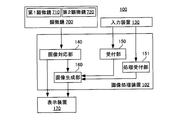
- FIG. 1 is a block diagram of a microscope system 100.
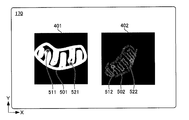
- FIG. The image displayed on the display apparatus 170 is shown.
- the image displayed on the display apparatus 170 is shown.
- 2 is a diagram illustrating a concept of processing in the image processing apparatus 101.
- FIG. 2 is a diagram illustrating a concept of processing in the image processing apparatus 101.
- FIG. 2 is a diagram illustrating a concept of processing in the image processing apparatus 101.
- FIG. 2 is a diagram illustrating a concept of processing in the image processing apparatus 101.
- FIG. The image displayed on the display apparatus 170 is shown.
- the image displayed on the display apparatus 170 is shown.
- 2 is a diagram illustrating a concept of processing in the image processing apparatus 101.
- FIG. 2 is a diagram illustrating a concept of processing in the image processing apparatus 101.
- FIG. 2 is a diagram illustrating a concept of processing in the image processing apparatus 101.
- FIG. 2 is a diagram illustrating a concept of processing in the image processing apparatus 101
- FIG. 3 is a flowchart illustrating a processing procedure in the image processing apparatus 101. It is a figure explaining the other example of step S102 of FIG. It is a figure explaining the further another example of step S102 of FIG. 1 is a block diagram of a microscope system 105. FIG. It is a figure explaining other combinations of a microscope picture. It is a figure explaining other combination of a microscope picture. A state where the first enlarged image 411 and the second enlarged image 412 are displayed on the display device 170 is shown. It is a figure explaining the other example using a time lapse image.
- FIG. 10 is a block diagram of a microscope system 100 including another image processing apparatus 102.
- FIG. 4 is a flowchart illustrating a procedure for executing processing in the image processing apparatus 102. It is a figure explaining the process which receives the scanning on the 1st microscope image 401 and the 2nd microscope image 402.
- FIG. 10 is a block diagram of another image processing apparatus 103. It is a figure explaining the process of the image processing apparatus. A state in which the superimposed image 414 is displayed is shown.
- 3 is a flowchart showing an operation procedure of the image processing apparatus 103. It is a figure explaining other operation
- FIG. 1 is a block diagram of a microscope system 100 including an image processing apparatus 101.
- the microscope system 100 includes a microscope 700, an input device 130, an image processing device 101, and a display device 170.
- the input device 130 is operated when an instruction from the user is input to the image processing device 101.
- an existing general-purpose input device such as a pointing device such as a mouse, a keyboard, or a touch panel is used.
- the input device 130 is used for input to the image processing apparatus 101, but an input device 130 installed for operating the first microscope 110 and the second microscope 120 may also be used.
- the display device 170 is a liquid crystal display panel or the like, and displays the display image output from the image processing device 101 in a state where the user can visually recognize the display image.
- the display device 170 may also be a display device provided for the first microscope 110, the second microscope 120, or the like for the purpose of displaying an image.
- the image processing apparatus 101 includes an image correspondence unit 140, a reception unit 150, and an image generation unit 160.
- the image processing apparatus 101 is configured by a general-purpose information processing apparatus controlled by a program that executes image processing to be described later.
- the image processing apparatus 101 processes the microscope image data acquired from the microscope 700 and generates an image to be displayed on the display device 170.
- the microscope 700 includes a first microscope 710 and a second microscope 720 that capture images of specimens using different microscope methods.
- the first microscope 710 and the second microscope 720 share at least part of the optical system in both microscopes (that is, at least part of the optical axes in both microscopes are coaxial).
- the first microscope 710 and the second microscope 720 may be optical systems in which the optical systems in both microscopes are independent.
- the first microscope 710 images a specimen by a SIM (Structured Illumination Microscope).
- the SIM illuminates the specimen with structured illumination having a periodic illumination pattern, and generates a super-resolution microscope image representing the microstructure of the specimen smaller than the illumination light wavelength based on interference fringes generated in the specimen image.
- This super-resolution microscope image is generated by reconstructing a plurality of images obtained by illuminating the specimen by changing the direction and position of the illumination pattern of structured illumination, respectively, by arithmetic processing.
- the expression “reconstruction” is hereinafter simply referred to as generation or imaging.
- the second microscope 720 images the specimen by STORM (Stochastic Optical Reconstruction Microscopy).
- STORM can reconstruct a fluorescent image (super-resolution microscope image) with a resolution higher than the wavelength of the illumination light by superimposing position information of fluorescent dyes detected with high accuracy from a plurality of fluorescent images.
- the expression “reconstruction” is hereinafter simply referred to as generation or imaging.
- the microscope 700 images the observation region including at least a part of the specimen with the first microscope 710, and generates the first microscope image data 401. Further, the microscope 700 captures an observation region including at least a part of the sample corresponding to the observation region captured by the first microscope 710 with the second microscope 720, and generates second microscope image data 402.
- the observation region of the second microscope 720 corresponding to the observation region of the first microscope 710 specifically refers to the specimen included in the imaging field of view of the first microscope 710 (that is, the region to be imaged). It is an imaging visual field of the second microscope 720 including at least a partial region. Therefore, the specimen image in the image captured by the second microscope 720 includes at least a part of the specimen image in the image captured by the first microscope 710.
- the first microscope image data 401 and the second microscope image data 402 are transmitted from the microscope 700 to the image processing apparatus 101.
- the first microscope image data 401 and the second microscope image data 402 are generated in a general-purpose format such as JPEG or BMP. Instead of this, it may be generated in a dedicated format that can be processed by the image processing apparatus 101. Since the image captured by the first microscope 710 is handled as data until it is displayed on the display device 170 (for example, processed as image data by the image processing device 101), hereinafter, the first microscope image data 401 is used. However, since the information indicated by the data is an image, for convenience of explanation, the same reference number is used to refer to the first microscope image 401. Similarly, the second microscope image data 402 is referred to as a second microscope image 402 by using the same reference numbers for convenience of explanation.
- FIG. 2 is a diagram showing a display screen of the display device 170.
- a first microscope image 401 and a second microscope image 402 at the time of acquisition are displayed on the image processing apparatus 101.
- the X axis and the Y axis are appropriately described in FIG. 2 and the subsequent drawings, these are for explaining the direction and do not mean a specific direction in the real space.
- the first microscope image 401 displayed on the left side in the figure includes a specimen image 501.
- the second microscope image 402 displayed on the right side in the drawing includes a specimen image 502 of the same specimen as the first microscope 710.
- the two specimen images 501 and 502 in both microscopic images have the magnification of the image (the size of the image).
- the orientation and position are different. That is, in the example of FIG. 2, the sample image 502 in the second microscope image 402 has a smaller dimension on the screen of the display device 170 than the sample image 501 in the first microscope image 401.
- the longitudinal direction of the specimen image 501 in the first microscope image 401 is substantially parallel to the X axis, whereas the specimen image 502 in the second microscope image 402 is inclined by about 45 ° from the X axis toward the Y axis. (Ie, leaning to the right). Furthermore, the specimen image 501 is located near the center of the first microscope image 401, while the specimen image 502 is located near the right end of the second microscope image 402.
- the first microscope image 401 and the second microscope image 402 are different in the size, inclination, and position of the specimen images 501 and 502 in each image. Therefore, even if the first microscope image 401 and the second microscope image 402 are displayed side by side on the display device 170, it is difficult for the user to compare and observe both images.
- FIG. 3 to 8 are diagrams for explaining the processing of the image corresponding unit 140.
- the image correspondence unit 140 performs processing for associating the first microscope image 401 and the second microscope image 402 as described below, for example.
- This associating process can be rephrased as a process of associating the pixel position, which is the two-dimensional coordinate position of the pixel constituting the first microscope image 401, with the pixel position, which is the two-dimensional coordinate position of the pixel constituting the second microscope image 402. it can.
- the associating process is performed.
- the process includes a process of specifying, in the second microscope image 402, a pixel having the same position on the microscope image as the pixel position in the first microscope image 401. Since the pixel position is a position in the first microscope image 401 and the second microscope image 402, it can also be called an image position.
- this associating process can be rephrased as a process of associating the first microscope image data 401 and the second microscope image data 402.
- the receiving unit 150 further receives from the user a designation of a position that is considered to correspond to a position designated in the first microscope image 401 in the second microscope image 402.
- the user designates in the second microscope image 402 a position that is considered to be the same part as the specimen part designated in the first microscope image 401.
- the image corresponding unit 140 displays the marker 512 at the designated position. In the example of FIG. 3, the position in the sample image 502 is designated.
- the user designates a position different from the marker 511 in the first microscope image 401 and the position designated in the first microscope image 401 in the second microscope image 402 (that is, a position different from the marker 511). ) (In other words, a position different from the marker 512) is input.
- the receiving unit 150 specifies the position in the first microscope image 401 and displays the marker 521, and specifies the position in the second microscope image 402 and displays the marker 522. indicate.
- the positions in the first microscope image 401 and the second microscope image 402 are designated, for example, when the user clicks the positions in the first microscope image 401 and the second microscope image 402 with a mouse, the positions are set.
- the location information to be specified is designated, and the reception unit 150 acquires the location information.
- 4 to 7 are diagrams illustrating the concept of processing executed by the image corresponding unit 140 after the position specified in FIG. 3 is specified.
- 4 to 8 show the first microscope image 401 and the second microscope image 402 as “images”, the image data processed inside the image processing apparatus 101 is shown for explanation. Thus, such an “image” is not generated or displayed on the display device 170.
- the image processing apparatus 101 handles the first microscope image 401 as data, hereinafter, it is also referred to as first microscope image data.
- the same reference number is used and the image is displayed. May be illustrated. The same applies to the second microscope image 402.
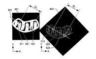
- FIG. 4 is a diagram for explaining processing of image data for aligning the orientation of the specimen image 501 in the first microscope image 401 and the specimen image 502 in the second microscope image 402.
- the image correspondence unit 140 generates data of a virtual straight line 601 that connects the markers 511 and 521 in the first microscope image 401.
- the image corresponding unit 140 generates data of a virtual straight line 602 that connects the markers 512 and 522 in the second microscope image 402.
- FIG. 5 is a diagram for explaining the next processing of FIG. 4 by the image corresponding unit 140.
- the image corresponding unit 140 displays the entire second microscope image 402 as shown by an arrow 611 in FIG.
- the second microscope image data 402 is processed so as to rotate from the state of FIG. 4 indicated by the dotted frame of 5 to the direction shown in FIG. 5 clockwise in FIG.
- the image correspondence unit 140 calculates a distance D 1 between the markers 511 and 521 of the first microscope image 401. Subsequently, the image corresponding unit 140 calculates a distance D 2 between the markers 512 and 522 of the second microscope image 402.
- FIG. 6 is a diagram for explaining the next processing of FIG. Since the relationship between the sizes of the distances D 2 and D 1 is D 2 ⁇ D 1 , when the sample image 502 (that is, the second microscope image 402) is multiplied by D 1 / D 2 , the sample image 501 as shown in FIG. That is, the size (magnification) coincides with (the first microscope image 401). Therefore, the image corresponding unit 140 processes the second microscope image data 402 so that the second microscope image 402 is multiplied by D 1 / D 2 .
- the image corresponding unit 140 displays the first microscope image 401 and the second microscope image in which the size, inclination, and position of the specimen image (that is, the first microscope image 401 and the second microscope image 402) are matched.
- the state displayed side by side on the screen of the apparatus 170 is shown.
- the image generation unit 160 matches the size, inclination, and position of the sample image 501 in the first microscope image 401 and the sample image 502 in the second microscope image 402 as illustrated in FIG. 7.
- the second microscope image 402 subjected to the image processing in this way only a portion having the same size as the first microscope image 401 is displayed on the display device 170.
- the specimen image 501 in the first microscope image 401 and the specimen image 502 in the second microscope image 402 have the same magnitude, inclination, and position. Therefore, the user can easily compare and observe the first microscope image 401 and the second microscope image 402.
- the image correspondence unit 140 processes the second microscope image data 402 so as to rotate, reduce, and further move the second microscope image 402, thereby obtaining the sample image 502 of the second microscope image 402.
- the size, orientation, and position of the sample were matched with the size, orientation, and position of the specimen image 501 of the first microscope image 401.
- the image corresponding unit 140 processes the first microscope image data 401 so as to rotate, enlarge, and move the first microscope image 401, and the size and direction of the specimen image 501 of the first microscope image 401.
- the position may be matched with the size, orientation, and position of the specimen image 502 of the second microscope image 402.
- FIG. 9 shows an image displayed on the display device 170 regarding the processing of the image generation unit 160.
- the specimen images of the first microscope image 401 and the second microscope image 402 are displayed in a state in which the sizes, orientations, and positions are aligned.
- designation of at least a part of position information in the first microscope image 401 is accepted.
- the image generation unit 160 displays a cursor 530 on the first microscope image 401 as shown in FIG. 9 by input from the user via the input device 130, for example, movement of the mouse. Furthermore, the reception unit 150 receives the position of a point designated by a user's mouse button pressing operation as position information (for example, the coordinates of the point). In FIG. 9, the user presses the mouse button at the position where the cursor 530 is displayed to specify a point. The position of the received point is displayed on the screen of the display device 170 by an X-shaped mark 531. Note that the accepting unit 150 may accept designation of a point by an operation such as depressing a return key, touching the display device 170 when the display device 170 is a touch panel, instead of depressing a mouse button.
- FIG. 10 is a diagram for explaining the processing of the image generation unit 160.
- the image generation unit 160 acquires position information (for example, point coordinates) of the point in the first microscope image 401 received by the reception unit 150 from the reception unit 150. Then, the image generation unit 160 specifies the first enlarged region 631 corresponding to the position of the point. More specifically, the image generation unit 160 expands a preset region including the point received by the reception unit 150 based on the position information of the point in the acquired first microscope image 401, that is, enlargement.
- the region 631 is specified.
- the first enlarged region 631 is a region surrounded by a circle with a preset radius 621 centered on the position of the mark 531.
- the receiving unit 150 may receive a designation using the position of the region in the first microscope image 401 as position information instead of the designation using the position of the point in the first microscope image 401 as the position information.
- a rectangle having a movement amount as a diagonal line is displayed by moving the mouse while dragging the mouse at a certain position, and the rectangle is displayed by the reception unit 150 by releasing the drag. May be accepted.
- the image generation unit 160 acquires information on the position of the designated rectangle (for example, the coordinates of the four vertices of the rectangle) from the reception unit 150, and is preset based on the information, including the designated rectangle.
- the specified area (for example, an area having a specified rectangular diagonal as a diameter) is specified as the first enlarged area 631.
- the receiving unit 150 may receive, as position information, coordinates of the first microscope image 401 (first microscope image data 401) that is directly input from the keyboard or the like as the input device 130.
- the coordinates of one point may be received so as to designate a point on the first microscope image 401, or the coordinates of a plurality of points (for example, a rectangular area) may be designated so as to designate an area on the first microscope image 401. If there are, the coordinates of four vertices) may be accepted.
- the image generation unit 160 acquires the received coordinates, and specifies the first enlarged region 631 including the points and regions corresponding to the coordinates. Further, the receiving unit 150 may receive a designation using the position of the first enlarged region 631 itself as position information. In this case, in the first microscope image 401, a circle having a movement amount as a diameter or a radius is displayed by moving the mouse while dragging at a certain position, and the circle is defined as a first enlarged region 631 by releasing the drag. It may be accepted. Then, the image generation unit 160 acquires information (for example, the center coordinates and radius of the circle) regarding the position of the designated circle (first enlarged region 631), and identifies the designated circle as the first enlarged region 631. . In any of the above cases, the designation of the region is not limited to a rectangle or a circle, and may be designated by another shape.
- the image generation unit 160 generates a first enlarged image 411 in which the first enlarged region 631 in the first microscope image 401 is enlarged.
- the enlargement magnification of the first enlarged image 411 may be a magnification set in advance in the image processing apparatus 101, or the image processing apparatus 101 may inquire the user after the position information is designated. It can be said that the first enlarged image 411 is an image displayed larger than the size when the first enlarged region 631 of the first microscope image 401 is displayed on the display device 170.
- the image generation unit 160 When generating the first enlarged image 411, if some of the pixels forming the image do not exist in the first microscope image 401 and the image is defective, the image generation unit 160 generates a complementary pixel.
- the missing pixels may be compensated. Since the first enlarged region 631 is at least a part of the first microscope image 401, it can be said that the first enlarged image 411 is an image obtained by enlarging at least a part of the first microscope image 401.
- FIG. 11 is a diagram for explaining the processing after FIG.
- the image generation unit 160 identifies a point in the second microscope image 402 corresponding to the point in the first microscope image 401 that has been designated by the reception unit 150. Specifically, the image generation unit 160 identifies the point of the position in the second microscope image 402 that is the same as the position of the point in the first microscope image 401 that has received the designation. In other words, the image generation unit 160 identifies in the second microscope image 402 a point having the same position on the microscope image as the position of the point in the first microscope image 401 that has received the designation. In other words, the image generation unit 160 identifies the pixel in the second microscope image 402 that is the same as the position of the pixel corresponding to the point in the first microscope image 401 that has received the designation.
- the image generation unit 160 specifies a circular region around the point specified in the second microscope image 402 and specifies the second enlarged region 632.
- the second enlarged region 632 has the same radius 622 as the first enlarged region 631.
- the image generation unit 160 enlarges the image of the second enlarged region 632 with respect to the second microscope image data 402 at the same magnification as the magnification of the first enlarged region 631, and generates the second enlarged image 412. .
- the second enlarged region 632 specified by the image generation unit 160 may not be set around the point (the point specified by the image generation unit 160) in the second microscope image 402, and the second enlarged image 412.
- the position where the second enlarged region 632 is set may be far from the center of the point (the point specified by the image generation unit 160) in the second microscope image 402 to the extent that there is no hindrance to the observation.
- the second enlarged image 412 is an enlarged image of a region including the point of the second microscopic image 402 corresponding to the point designated to be enlarged in the first microscopic image 401. 411.
- the second enlarged image 412 generated by the image generation unit 160 in relation to the first enlarged image 411 is not limited to the one corresponding to the position of each point, and may have some relationship. Good.
- the second enlarged region 632 is at least a part of the second microscope image 402, it can be said that the second enlarged image 412 is an image obtained by enlarging at least a part of the second microscope image 402.
- FIG. 12 is an example in which the first enlarged image 411 and the second enlarged image 412 are displayed on the display device 170.
- the image generation unit 160 superimposes the first enlarged image 411 on the first microscope image 401 and displays it on the display device 170.
- the center of the first enlarged image 411 coincides with the position of the point that is designated by the accepting unit 150 in the first microscope image 401. Therefore, the first enlarged image 411 displays the area around the point where the designation of the first microscope image 401 is accepted as if it is being magnified and observed with a magnifying glass. Since the entire image can be observed, an enlarged image can be observed with respect to the region that the user has focused on (that is, the region including the position specified in the first microscope image 401), so that the microscope image can be observed intuitively. Work can be carried out.
- the image generation unit 160 displays the second enlarged image 412 superimposed on the second microscope image 402.
- the center of the second enlarged image 412 coincides with the position of the point specified by the image generation unit 160 in the second microscope image 402. Therefore, the second magnified image 412 displays the area around the point specified in the second microscope image 402 as if it were magnified and observed with a magnifying glass, so that the user can view the entire second microscope image 402. Intuitive observation of a microscope image can be performed while looking down.
- the first microscopic image 401 (specimen image) and the second microscopic image 402 (specimen image) are displayed in advance with the size (magnification), orientation, and position matched.
- the first enlarged image 411 and the second enlarged image 412 are enlarged at the same magnification with respect to the displayed first microscope image 401 and second microscope image 402, respectively.
- the images of the first microscope image 401 and the second microscope image 402 are captured.
- the entire comparative observation can be easily performed. Furthermore, it is possible to easily carry out comparative observation on the region noted by the user in the first microscope image 401 and the second microscope image 402.
- the user designates the position of the point to be enlarged in the first microscope image 401, not only the first enlarged image 411 of the area including the position but also the second enlarged image 412 of the area including the corresponding point is displayed.
- the device 170 is displayed. Therefore, the first magnified image 411 and the second magnified image 412 can be easily compared and observed without the trouble of specifying the position of the point to be magnified in each of the first microscope image 401 and the second microscope image 402.
- the image generation unit 160 extracts a part of the second microscope image 402 that overlaps the first enlarged image 411.
- the first enlarged image 411 may be displayed hidden.
- the image generation unit 160 extracts a part of the first microscope image 401 that overlaps the second enlarged image 412.
- the second enlarged image 412 may be displayed hidden.
- the image generation unit 160 may fill a plain image.
- FIG. 13 is a flowchart showing a processing procedure in the image processing apparatus 101.
- the image processing apparatus 101 acquires a first microscope image 401 (first microscope image data) and a second microscope image 402 (second microscope image data) from the microscope 700 (S101).
- the image corresponding unit 140 uses the method illustrated in FIGS. 3 to 7 to perform the first microscope image 401 and the second microscope image 402 on the first microscope image 401 and the second microscope image 402.
- the association is executed (S102).
- the image association unit 140 matches the size, orientation, and position of the specimen images of the first microscope image 401 and the second microscope image 402 and displays them on the display device 170 as shown in FIG. S103).
- the image generation unit 160 specifies the second enlarged region 632 of the second microscope image 402 (S106).
- the first microscope image 401 and the second microscope image 402 have the same size, orientation, and position of the specimen image, as described with reference to FIG. 11, the first microscope input in step S104.
- the position of the point in the second microscope image 402 that is the same as the position of the point in the image 401 is specified as the position of the center of the second enlarged region 632.
- the image generation unit 160 generates a second enlarged image 412 in which the second enlarged region 632 in the second microscope image 402 is enlarged (S107).
- the image generation unit 160 displays the first microscope image 401 and the second microscope image 402, the first enlarged image 411, and the second enlarged image 412 side by side on the display device 170. (S108).
- a communication unit that can acquire a microscope image from the outside of the microscope system 100 may be provided in the image processing apparatus 101.
- the communication unit may acquire the first microscope image 401 or the second microscope image 402 from an external database or the like through the Internet, a dedicated line, etc., and use it for the image processing apparatus 101.
- step S102 of FIG. 13 instead of accepting designation of a position used for associating the first microscope image 401 and the second microscope image 402 from the user, they are included in the first microscope image 401 and the second microscope image 402.
- the image corresponding unit 140 may automatically extract a plurality of marker images and use the positions.
- a marker is introduced around the specimen or the specimen.
- existing markers such as gold fine particles and fluorescent labels can be used.
- the image correspondence unit 140 is a method similar to the method described with reference to FIGS. 3 to 7, and the positions of the plurality of marker images in the first microscope image 401 (position coordinates in the first microscope image 401). And the rotation amount, size ratio, and movement amount of the second microscope image 402 such that the positions of the plurality of marker images in the second microscope image 402 coincide with each other (position coordinates in the second microscope image 402). calculate.
- step S102 the user automatically designates the first microscope image 401 and the first microscope image 401 without specifying the position for association with the first microscope image 401 and the second microscope image 402. Since the two microscope images 402 can be associated with each other, the labor of comparative observation between the first microscope image 401 and the second microscope image 402 is reduced.
- the position of the marker introduced around the specimen and the specimen does not change when the first microscope image 401 and the second microscope image 402 are imaged, by using the marker image for association, Accurate association can be performed.
- the user may specify a plurality of markers in the first microscope image 401 and a plurality of markers in the second microscope image 402.
- the image association unit 140 may associate the microscope images with each other using morphological features appearing in both the first microscope image 401 and the second microscope image 402. For example, cell surface protrusion structures, intracellular mitochondrial shapes, cover glass scratches, and the like may be used as markers.
- the image correspondence unit 140 may automatically extract the images of these markers and execute the association between the microscopic images.
- the image correspondence unit 140 accepts designation of the positions of these marker images by the user. The association between the microscope images may be executed.
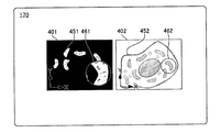
- FIG. 14 is a diagram for explaining another example of step S102 in FIG.
- a first microscope image 401 is an image obtained by SIM
- a second microscope image 402 is an image obtained by an electron microscope.
- sample images 451 and 452 appear as they are in the microscope image of the SIM and the microscope image of the electron microscope. Therefore, in step S102 of FIG. 13, the image correspondence unit 140 performs pattern matching between the first microscope image 401 by the SIM and the second microscope image 402 by the electron microscope, thereby obtaining the first microscope image 401 and the second microscope image 402. Associate.
- the image corresponding unit 140 instead of accepting designation of a plurality of positions in both microscope images from the user in step S102 of FIG. 13, uses the pattern of the first microscope image 401 and the second microscope image 402. Perform matching. In this case, the image corresponding unit 140 calculates the rotation amount, magnification, and position displacement amount of the second microscope image 402 with respect to the first microscope image 401, in which the similarity between the microscope images is the highest. Then, as shown in FIG. 8, the image corresponding unit 140 performs image processing on the second microscope image 402 (second microscope image data) based on these calculated values, and the first microscope image 401 and the second microscope image. 402 is associated.
- the microscope images can be easily associated with each other by pattern matching, and the labor for comparative observation between the microscope images is reduced.
- pattern matching a known method such as a normalized correlation method or a geometric shape pattern matching method is used. Pattern matching is paraphrased as template matching.
- compatible part 140 does not need to perform pattern matching using the whole image in each microscope image.
- the accepting unit 150 accepts designation from the user as an area for performing pattern matching for a partial area of the first microscope image 401, and the image correspondence unit 140 uses the second area and the second area in the designated first microscope image 401.
- the microscope image 402 may be pattern-matched, and the accepting unit 150 accepts designation of a part of the second microscope image 402 from the user, and the image corresponding unit 140 accepts the designated first microscope image.
- the region in 401 and the designated region in the second microscope image 402 may be pattern-matched.
- a foreign object such as dust
- texture such as a stain
- FIG. 15 is a diagram for explaining a modification of the pattern matching in FIG.
- the image corresponding unit 140 performs pattern matching between the first enlarged image 461 and the second microscope image 402 instead of the pattern matching between the first microscope image 401 and the second microscope image 402 described in FIG. Do.
- the image corresponding unit 140 receives an input of a position to be enlarged for pattern matching from the user via the input device 130 in step S102 of FIG.
- the image corresponding unit 140 performs pattern matching using a pattern included in the first enlarged image 461 at the position as shown in FIG.
- the pattern matching method is the same as described in FIG.
- the range of the first enlarged image 461 is narrower than that of the first microscope image 401.
- the possibility that dust or the like is included in the first enlarged image 461 is reduced, and the possibility of erroneous detection of pattern matching can be reduced.
- the pattern included in the first enlarged image 461 is searched for the second microscope image 402.
- the specification of the position to be enlarged in the second microscope image 402 may be received, and the pattern included in the enlarged image obtained by enlarging the area including the position may be pattern-matched with the first microscope image 401.
- the image association unit 140 sets the microscope 700 when the first microscope image 401 is captured and the setting of the microscope 700 when the second microscope image 402 is captured.
- Conditions may be acquired, and the first microscope image 401 and the second microscope image 402 may be associated with each other based on the conditions.
- the setting conditions include the imaging magnification of the microscope, stage coordinates, and the like.
- the image correspondence unit 140 may associate the microscope images using both the imaging magnification and the stage coordinates, or may associate using either one.
- the imaging magnification is a magnification at which an image of a specimen is imaged on an imaging surface of an imaging device (CCD, CMOS, etc.) of the microscope when the specimen on the stage is imaged with each microscope.
- the image correspondence unit 140 determines the magnification of the sample image 501 in the first microscope image 401 and the first microscope from the imaging magnification when the first microscope image 401 is captured and the imaging magnification when the second microscope image 402 is captured.
- the magnification of the sample image 502 in the image 401 can be associated. Thereby, for example, the size of the sample image 501 in the first microscope image 401 when displayed on the display device 170 and the size of the sample image 502 in the second microscope image 402 can be matched. Therefore, both comparative observations become easy.
- the stage coordinates are the coordinates of the stage on which the specimen is placed, which is acquired when the specimen is imaged with each microscope.
- the image correspondence unit 140 determines the position of the sample image 501 in the first microscope image 401 and the second microscope image 402 from the stage coordinates when the first microscope image 401 is captured and the stage coordinates when the second microscope image 402 is captured. Can be associated with the position of the sample image 502. Thereby, for example, the position of the specimen image 501 in the first microscope image 401 when displayed on the display device 170 and the position of the specimen image 502 in the second microscope image 402 can be matched. Therefore, both comparative observations become easy.
- step S103 of FIG. 13 the size, orientation, and position of the image are displayed based on the correspondence between the first microscope image 401 and the second microscope image 402.
- the second microscope image 402 may be omitted from displaying the image in the same size, orientation, and position.
- step S102 the method of associating the microscope images described with reference to FIGS. 3 to 7, the method of associating the microscope images described with reference to FIGS. 14 and 15, and the above-described imaging of the microscope images.
- the image generation unit 160 determines the size of each image specified in the association between the first microscope image 401 and the second microscope image 402. Based on the orientation and position, the second enlarged area is identified in step S106 in correspondence with the identification of the first enlarged area in step S105.
- FIG. 16 is a block diagram of a microscope system 105 using another microscope image
- FIG. 17 is a diagram illustrating a microscope image used in the microscope system 105.
- the microscope system 105 is different from the microscope system 100 in that the microscope 700 is a single unit.
- the same components as those in the microscope system 100 are denoted by the same reference numerals, and description thereof is omitted.
- the image association unit 140 acquires a group of microscope images captured at a plurality of focal planes from a single microscope 700.
- the image corresponding unit 140 generates stereoscopic microscope image data (stereoscopic microscope image) having three-dimensional luminance distribution information by synthesizing the microscope images (luminance distribution) of the microscope image group.
- the accepting unit 150 designates two plane microscope image data (planar microscope images) to be cut out from the stereoscopic microscope image data (stereoscopic microscope image) as planes parallel to each other as the first microscope image 401 and the second microscope image 402. Accept.
- the reception unit 150 receives the designation of the first microscope image 401 and the second microscope image 402 with the mouse by the user.
- the image correspondence unit 140 further associates the first microscope image 401 and the second microscope image 402 in step S102 of FIG.
- the image correspondence unit 140 performs the method of associating the microscope images described with reference to FIGS. 3 to 7, the method of associating the microscopes described with reference to FIGS. Any method of performing association using the setting information of the microscope may be used. Thereby, for example, even when the specimen moves with a time difference that occurs when different focal planes are imaged, it is possible to appropriately associate them. Therefore, even if the planar microscope images are cut out on different planes, the size, orientation, and position of the specimens of both microscope images are aligned, so that they can be comparatively observed easily.
- step S103 in FIG. 13 the operations after step S103 in FIG. 13 are performed. Specifically, the image corresponding unit 140 displays the first microscope image 401 and the second microscope image 402 on the display device 170 (S103 in FIG. 13).
- the image generation unit 160 specifies the first enlarged region 631 of the first microscope image 401 (S105 in FIG. 13). ), A first enlarged image 411 in which the first enlarged region 631 in the first microscope image 401 is enlarged is generated (S109 in FIG. 13).
- the image generation unit 160 identifies the second enlarged region 632 of the second microscope image 402 (S106 in FIG. 3), and expands the second enlarged region 432 of the second microscope image 402 as a second enlarged image 412. Generate (S107 in FIG. 13). Further, as described with reference to FIG. 12, the image generation unit 160 displays the first microscope image 401 and the second microscope image 402, the first enlarged image 411, and the second enlarged image 412 side by side on the display device 170. (S108 in FIG. 13).
- stereo microscope image data was generated from a group of microscope images acquired from a single microscope 700.
- stereo microscope image data may be generated by acquiring microscope images from a plurality of microscopes and synthesizing the plurality of microscope images.
- the direction of each plane from which the stereoscopic microscope image is cut out may be freely specified by the user via the input device 130.
- the first microscope image 401 and the second microscope image 402 planes parallel to each other in an arbitrary direction may be cut out from the stereoscopic microscope image data (stereoscopic microscope image). If there is no hindrance to the comparative observation, the first microscope image 401 and the second microscope image 402 may be cut out of planes that are not parallel to each other in the stereoscopic microscope image data (stereoscopic microscope image).
- the same objective lens is often used for detection of fluorescence intensity at each focal plane.
- the image correspondence unit 140 may omit the process of matching the size of the image.
- the first microscope image 401 and the second microscope image 402 may have the same orientation, size, and position. In this case, the association between the first microscope image 401 and the second microscope image 402 shown in FIGS. 3 to 7 in step S102 of FIG. 13 may be omitted.
- FIG. 18 is a diagram illustrating another combination of microscope images used in the microscope system 105 of FIG.
- the microscope image group 450 in FIG. 18 includes a plurality of microscope images obtained by photographing the observation region (imaging field of view of the microscope) at arbitrary elapsed times (so-called image group acquired by time-lapse photography).
- the image association unit 140 acquires a group of microscope images that have been time-lapse shot with a single microscope 700.
- the image groups in the time ranges different from each other in the microscope image group 450 are displayed in two columns.
- the image corresponding unit 140 receives the designation of the first microscope image 401 and the second microscope image 402 acquired from different time ranges in the microscope image group 450 via the input device 130 in step S102 of FIG. In other words, in this example, as the first microscope image 401 and the second microscope image 402, microscope images with different times taken are designated.
- the image correspondence unit 140 further associates the first microscope image 401 and the second microscope image 402 with the method described with reference to FIGS. As a result, even when the sample moves with the time difference of imaging, it is possible to appropriately associate.
- the image corresponding unit 140 displays the first microscope image 401 and the second microscope image 402 on the display device 170 in step S103 of FIG.
- the accepting unit 150 accepts designation of position information to be enlarged in the first microscope image 401 via the input device 130 in step S104 of FIG.
- step S105 in FIG. 13 the operations after step S105 in FIG. 13 are performed. Specifically, when position information is input from the user via the input device 130, the image generation unit 160 specifies the first enlarged region 631 of the first microscope image 401 (S105 in FIG. 13), and A first enlarged image 411 in which the first enlarged region 631 in the one microscope image 401 is enlarged is generated (S109 in FIG. 13).
- the image generation unit 160 will be described with reference to FIGS. 10 and 11 based on the size, direction, and position of each image specified in the association between the first microscope image 401 and the second microscope image 402. As described above, the position of the point of the second microscope image 402 corresponding to the position of the point of the first microscope image 401 designated by the user is specified (S106 in FIG. 3). Furthermore, the image generation unit 160 generates a second enlarged image 412 in which a region including the identified point of the second microscope image 402 is enlarged (S107 in FIG. 3).
- the image generation unit 160 displays the first microscope image 401 and the second microscope image 402, the first enlarged image 411, and the second enlarged image 412 side by side on the display device 170. (S108 in FIG. 13).
- the image generation unit 160 superimposes the first enlarged image 411 on the first microscope image 401 and also superimposes the second enlarged image 412 on the second microscope image 402 and displays it on the display device 170 (S108 in FIG. 13).
- the first enlarged image 411 and the first enlarged image 411 which are partial enlarged images of the first microscope image 401 and the second microscope image 402, which are selected from the microscope image group 450 generated by time-lapse photography and have different times of imaging, are used.
- Two enlarged images 412 can be displayed on the display device 170 for comparative observation. Therefore, comparative observation of time-lapse images can be easily performed.
- the image generation unit 160 displays the first microscope image 401 and the second microscope image 402 on the display device 170 over time.
- the first enlarged image 411 is switched corresponding to the first microscope image 401 displayed sequentially.
- the second enlarged image 412 is also switched along with the second microscope image 402 that is sequentially displayed. This makes it possible to efficiently compare and observe temporal changes in phenomena occurring in the specimen.
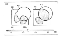
- the image generation unit 160 accepts switching of the first enlarged image 411 and the second enlarged image 412 displayed on the display device 170 from the user by operating the slider 551. Specifically, the image generation unit 160 determines the length of time-lapse shooting time represented by the image groups arranged in two rows in FIG. 18 (if the time lengths indicated by the two rows of image groups are the same, the time If one of the time lengths is different, the length of the bar 552 is displayed on the display device 170 as shown in FIG. The bar 552 indicates a range in which the user can move the slider 551. When the operation of the slider 551 is received via the input device 130, the image generation unit 160 specifies the time corresponding to the position from the position on the bar 552 of the slider 551.
- the image generation unit 160 specifies the first microscope image 401 and the second microscope image 402 corresponding to the specified time from the respective image groups, and the first enlarged image 411 and the second microscope image of the specified first microscope image 401. Displayed together with the second enlarged image 412 of 402. Thereby, the user can observe the respective temporal changes of the first enlarged image 411 and the second enlarged image 412 by operating the slider 551, and can further improve the efficiency of comparative observation.
- a microscope image that was time-lapse photographed with a single microscope was used, but instead, a microscope image was obtained from each of a plurality of microscopes, and the plurality of microscope images were photographed. It is good also as the microscope image imaged by the time lapse by arranging in order.
- the first microscope image 401 and the second microscope image 402 are acquired from an image obtained by observing one specimen in time order.
- the first microscopic image 401 and the second microscopic image 402 may not be included in the group of microscopic images taken in a series of time passages.
- the first microscopic image 401 is selected from a group of microscopic images obtained by applying reagent A to the sample and taking an image with time, and then applying reagent B to the sample and taking an image with time.
- the second microscope image 402 may be selected from the microscope image group.
- the same reagent is given to different specimens, and the first microscopic image 401 and the second microscopic image 402 are selected from the respective microscopic image groups obtained by imaging the respective specimens over time. Also good.
- the slider 551 in FIG. 19 specifies the first microscope image 401 and the second microscope image 402 from among images obtained by cutting out a plurality of planes in the stereoscopic microscope image data, as described with reference to FIG.
- the image generation unit 160 displays these microscopic images on the display device 170.
- the receiving unit 150 stores the position of the slider 551 in association with the position of the plane from which the stereoscopic microscope image data is cut out.
- the receiving unit 150 specifies the position of the plane from which the stereoscopic microscope image data is cut out from the received position of the slider 551, and the image generating unit 160.
- the image generation unit 160 displays a planar microscope image on the plane on the display device 170.
- FIG. 20 is a diagram for explaining another example using a time-lapse image.
- the time-lapse image described with reference to FIGS. 18 and 19 there are cases where the position or region of interest of the user moves. Therefore, in this example, it is detected to which position in the first microscopic image 401 and the second microscopic image 402 that the position that has been designated to be enlarged in the first microscopic image 401 has moved after that. .
- the pattern matching described with reference to FIGS. 14 and 15 can be used.
- the image corresponding unit 140 acquires a group of microscope images that are time-lapse shot with a single microscope 700.
- the image corresponding unit 140 receives designation of the first microscope image 401 and the second microscope image 402 acquired from different time ranges in the above-described microscope image group via the input device 130.
- the image processing apparatus 101 operates as follows instead of steps S102 to S107 in FIG.
- the receiving unit 150 receives from the input device 130 the designation of the position of the first microscope image 401 that the user wants to pay attention to, and the image handling unit 140 identifies the region 453 that includes the position.
- the image correspondence unit 140 uses the region 453, the image correspondence unit 140 performs pattern matching with a plurality of first microscope images 401 at times later than the currently displayed first microscope image 401.
- the image corresponding unit 140 enlarges each of the regions detected as having high similarity to the region 453 in the plurality of first microscope images 401 at a time later than the first microscope image 401, thereby One enlarged image 411 is generated.
- the image corresponding unit 140 further uses the region 453 to perform pattern matching with the currently displayed second microscope image 402 and a plurality of second microscope images 402 at the subsequent times, and the first microscope image 401 and the second microscope The image 402 is associated. Thereby, the image corresponding unit 140 enlarges each of the regions 454 detected as having a high similarity to the region 453 in the plurality of second microscope images 402, and generates a plurality of second enlarged images 412.
- the image generation unit 160 displays the first enlarged image 411 and the second enlarged image on the display device 170 over time. Thereby, even if the position and area which a user pays attention to have moved in the time lapse image, enlarged images obtained by enlarging the position and area can be easily compared.
- the first microscope image 401 and the first enlarged image 411 are not changed, and only the second microscope image 402 and the second enlarged image 412 are changed over time. It may be displayed.
- FIG. 21 is a block diagram of a microscope system 100 including another image processing apparatus 102.
- the image processing apparatus 102 has the same structure as the image processing apparatus 101 shown in FIG. Elements common to the image processing apparatus 101 are denoted by the same reference numerals, and redundant description is omitted.
- the image processing apparatus 102 is different from the image processing apparatus 101 in that in addition to the reception unit 150 that receives the position specified by the input device 130, the image processing apparatus 102 includes a processing reception unit 151 that similarly receives a display condition input from the input device 130.
- the display condition is a condition for changing the display on the display device 170 by processing the first enlarged image 411 once generated.
- the display conditions include a range enlarged by the first enlarged image 411, an image magnification, an image brightness, an image contrast, an image rotation, and an image inversion.
- FIG. 22 is a diagram illustrating a case where a range to be enlarged by the first enlarged image 411 is designated as the display condition.
- the user drags the outline of the first enlarged image 411 with the cursor 530 on the first enlarged image 411 displayed on the display device 170 to specify the changed size.
- the user can instruct the enlargement of the display area of the first enlarged image 411 by dragging the cursor 530 toward the outside in the radial direction of the first enlarged image 411.
- the user determines the size of the first enlarged image 411 after image processing by releasing the drag at a desired position.
- FIG. 23 is a diagram for explaining processing subsequent to FIG.
- the image generating unit 160 converts the initial first enlarged image 411 to the range of the first enlarged image 421 corresponding to the enlarged display range. Expanding. Accordingly, the image processing apparatus 102 enlarges the initial second enlarged image 412 to the same size as the enlarged first enlarged image 421, and generates an enlarged second enlarged image 422.
- the first microscope image 401 and the second microscope image 402 have the same size, orientation, and position, the first microscope image 401 (specimen image) and the second microscope image 402 (specimen image).
- the enlargement process is performed at the same position, the same magnification, and the same range. Thereby, the enlarged first enlarged image 421 and the enlarged second enlarged image 422 are juxtaposed.
- FIG. 24 is a flowchart showing a process execution procedure in the image processing apparatus 102.
- steps S101 to S108 are the same as FIG.
- the process accepting unit 151 inputs display conditions in this state.
- the presence or absence of is accepted (S121).
- the image generating unit 160 executes image processing under the display condition on the first enlarged image 411 (S122). In addition, the image generation unit 160 causes the image processing executed on the first enlarged image 411 to be reflected and executed on the second enlarged image 412 generated corresponding to the first enlarged image 411 (S123). ).
- the image generation unit 160 generates a first enlarged image 421 and a second enlarged image 422 after image processing (S124), and displays them on the display device 170 (S125). Thereby, the process performed when the process reception part 151 receives display conditions is completed.
- the image processing apparatus 102 can further perform image processing on the first enlarged image 411 and the second enlarged image 412 according to the input display conditions after the processing by the image generation unit 160 is once completed. Thereby, it is possible to make the first enlarged image 411 and the second enlarged image 412 after processing displayed on the display device 170 easier to see and further improve the efficiency of comparative observation.
- the image processing apparatus 102 also performs image processing equivalent to the first enlarged image 411 for the second enlarged image 412 when the display condition for the first enlarged image 411 is input. Thereby, since the trouble of designating the display conditions of the first enlarged image 411 and the second enlarged image 412 can be saved, both can be compared and observed efficiently.
- the designation method when the display condition is designated in step S121 is not limited to the method of operating the movement of the cursor on the first enlarged image 411.
- a menu listing the types of image processing and the parameter values as options may be displayed, and the contents designated by the menu may be selected.
- the actual size of the sample may be specified by a numerical value, or specified by the number of pixels on the display device 170, the magnification with respect to the size of the original area, or the like. May be.
- a plurality of first enlarged images 411 having different sizes may be displayed and selected from them.
- the process accepting unit 151 may accept a display condition other than the range enlarged in the first enlarged image 411 described in FIG. 23 as the display condition.
- the image generation unit 160 rotates the first enlarged image 411 and superimposes it on the first microscope image 401.
- the image generation unit 160 also rotates the second enlarged image 412 and superimposes it on the second microscope image 402.
- the image generation unit 160 makes the second enlarged image 412 the same angle as the first enlarged image 411. Rotate.
- the process accepting unit 151 may accept image magnification, image brightness, image contrast, and image inversion as further display conditions. Regardless of which display condition is accepted, the image generation unit 160 generates a first enlarged image 411 and a second enlarged image 412 after image processing according to the display condition, and the first microscope image 401 and the second microscope image 402. Are displayed on the display device 170 in a superimposed manner. Thereby, since the trouble of designating each of the processing of the first enlarged image 411 and the second enlarged image 412 can be saved, both can be compared and observed efficiently.
- the receiving unit 150 may receive an instruction to move the first enlarged image 411.
- the reception unit 150 receives the movement, and the direction and amount of movement are received by the image generation unit.
- the image generation unit 160 moves the first enlarged region 631 in the first microscope image 401 by the movement direction and the movement amount received by the receiving unit 150, and enlarges the first enlarged region 631 after the movement. 411 is generated. Further, the image generation unit 160 moves the second enlarged region 632 in the second microscope image 402 by the movement direction and the movement amount received by the receiving unit 150, and expands the second enlarged region 632 after the movement.
- the process accepting unit 151 may accept a change in the position where the first enlarged image 411 is displayed.
- the process accepting unit 151 accepts the movement and generates an image of the moving direction and the moving amount.
- the image generation unit 160 displays the first enlarged image 411 at the moved position with the movement direction and movement amount received by the processing reception unit 151, and the second enlarged image 412 also moves at the same movement direction and movement amount. To display. Thereby, on the display device 170, the second enlarged image 412 is also moved and displayed in synchronization with the movement of the first enlarged image 411.
- the second enlarged image 412 also moves together in response to an instruction to move the first enlarged image 411, the user moves the first enlarged image 411 and the second enlarged image 412 to a place where the user can easily see them, and easily compares and observes both. can do.
- FIG. 25 and FIG. 26 are diagrams for describing processing for accepting scanning on the first microscope image 401 and the second microscope image 402 instead of accepting the display condition in step S121 of FIG.
- the user when comparatively observing the first enlarged image 411 and the second enlarged image 412, the user can instruct the processing reception unit 151 in the scanning mode.
- the scanning mode the position at which scanning starts, the direction of scanning, and the position at which scanning ends are set by default, but may be specified by the user via the input device 130.
- the image generation unit 160 scans the first microscope image 401 along the scanning direction from the start point of the first microscope image 401, and sequentially generates and displays the first enlarged image 411 including the scanning position.
- FIG. 25 shows the first enlarged image 411 and the second enlarged image at the starting point
- FIG. 26 shows the first enlarged image 411 and the second enlarged image in the middle of the scanning.
- the image generation unit 160 sequentially generates and displays second enlarged images 412 at corresponding positions of the second microscope image 402 in synchronization with the scanning of the first microscope image 401.
- the scanning mode described with reference to FIGS. 25 and 26 can also be used for comparative observation of a plurality of well samples arranged two-dimensionally on a well plate. For a plurality of wells, the amount, concentration, type, and time elapsed since administration of the drug are different from each other.
- the image corresponding unit 140 captures a first microscope image 401 obtained by imaging a specimen of a specific well and a plurality of specimens obtained by imaging a plurality of well samples different from the specific well.
- the second microscopic image 402 is acquired.
- the reception unit 150 receives designation of the position of the point to be enlarged in the first microscope image 401, and the image generation unit 160 generates a first enlarged image 411 in which the region including the point in the first microscope image 401 is enlarged.
- the receiving unit 150 may receive designation of the position of the area of the first microscope image 401 instead of designation of the position of the point of the first microscope image 401.
- the image generation unit 160 specifies a point in each of the plurality of second microscope images 402 corresponding to the point in the first microscope image 401 for which the designation is received by the reception unit 150. Specifically, the image generation unit 160 has the same position (second microscope) as the point position (position coordinates in the first microscope image 401) in the first microscope image 401 that has received the designation. A point of position coordinates in the image 402 is specified. The image generation unit 160 further generates a plurality of second enlarged images 412 obtained by enlarging a region including the point of the plurality of second microscope images 402, and displays the plurality of second enlarged images 412 together with the first enlarged image 411. The information is sequentially displayed on the device 170.
- each of the first microscope image 401 and each of the plurality of second microscope images 402 may be specified using the pattern matching described with reference to FIGS. 14 and 15.
- the image generation unit 160 starts scanning based on the input from the user or the default setting, as described with reference to FIGS. 25 and 26.
- the direction of scanning and the position at which scanning ends are specified, and the second enlarged image 412 of the well corresponding to the position on the scanning is sequentially displayed.
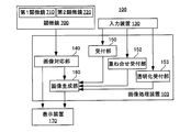
- FIG. 27 is a block diagram of another image processing apparatus 103.
- the image processing apparatus 103 has the same configuration as the image processing apparatus 101 shown in FIG. Therefore, the same reference numerals are assigned to the common configurations, and duplicate descriptions are omitted.
- the image processing apparatus 103 further includes a transparency receiving unit 152 and an overlay receiving unit 153 that receive an instruction from the input device 130.
- the transparency accepting unit 152 accepts a transparency instruction from the user input through the input device 130.
- the overlay receiving unit 153 receives an image overlay instruction from the user input through the input device 130.
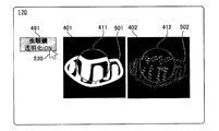
- FIG. 28 is a diagram for explaining the processing of the image processing apparatus 103.
- the image corresponding unit 140 displays the image on the display device 170 before the transparency instruction is input.
- a first enlarged image 411 and a second enlarged image 412 are displayed so as to overlap the first microscope image 401 and the second microscope image 402, respectively.
- a button 491 that supports transparency is further displayed.
- the image generation unit 160 that has acquired the instruction through the transparency reception unit 152 uses the cursor 530 operated by a pointing device such as a mouse to perform the first enlarged image 411 and the second enlarged image. Which of the images 412 is to be made transparent is selected. In the illustrated example, the first enlarged image 411 is selected and made transparent.
- transparency means translucency so that the content of the 1st expansion image 411 can be understood and the foundation
- the image processing apparatus 103 displays a slider 551 for adjusting the transmittance on the display device 170 so that the user can set the transmittance.
- the overlay receiving unit 153 receives an instruction when the user inputs an instruction for overlapping through the input device 130.
- the image generation unit 160 executes an overlay process for generating a superimposed image 414 in which the first enlarged image 411 and the second enlarged image 412 are overlaid. .
- the overlay receiving unit 153 moves the first enlarged image 411 by dragging the cursor 530 on the first enlarged image 411 and superimposes it on the second enlarged image 412. Judge that there was. Instead of moving the first enlarged image 411 by dragging, a superimposing instruction may be received by a button, a menu item, or the like. When a superimposition instruction is received by a button, menu item, or the like, the superposition image may be displayed at one of the first enlarged image 411 and the second enlarged image 412, or the first enlarged image 411 and The superimposed image may be displayed at a position different from any position of the second enlarged image 412.
- FIG. 29 shows a state in which the superimposed image 414 is displayed.
- the image generation unit 160 uses the first enlarged image 411 that has been previously transparentized as an upper layer in the region where the first enlarged image 411 and the second enlarged image 412 overlap each other, and the second enlarged image that has not been made transparent.
- the superimposing process with 412 as the background is executed. Thereby, it becomes easy to grasp the difference between the first enlarged image 411 and the second enlarged image 412. Therefore, the efficiency of comparative observation between the first microscope image 401 and the second microscope image 402 is improved.
- the image generation unit 160 may be configured to replace the enlarged image to be transparent and the enlarged image to be used as a background according to a user instruction.
- one of the first enlarged image 411 and the second enlarged image 412 may be subjected to image processing so as to have a color, brightness, or the like different from the other image.
- image processing is performed so that one image of the first enlarged image 411 and the second enlarged image 412 has a different color from the other image
- one image of the first enlarged image 411 and the second enlarged image 412 is changed to the other image.
- Image processing may be performed so that the color tone is different from that of the first image. This makes it easier to compare the first enlarged image 411 and the second enlarged image.
- FIG. 30 is a flowchart showing the operation procedure of the image processing apparatus 103.
- steps S101 to S108 are the same as those in FIG.
- the transparency receiving unit 152 makes the transparency in this state. Is received (S131).
- the image generating unit 160 performs transparency on the first enlarged image 411, for example (S132).
- the overlay receiving unit 153 waits while monitoring the presence / absence of an overlay instruction (S133: NO).
- the image generating unit 160 When the overlay receiving unit 153 receives an overlay instruction (S133: YES), the image generating unit 160 generates the superimposed image 414 by superimposing the first enlarged image 411 and the second enlarged image 412 (S134). . The image generation unit 160 causes the display device 170 to display the superimposed image 414 generated on the second microscope image 402 (S135). Thus, the image processing by the image processing apparatus 103 is completed.
- FIG. 31 is a diagram for explaining still another operation of the image processing apparatus 101.
- a first microscope image 401, a second microscope image 402, a first enlarged image 411, and a second enlarged image 412 are displayed as in FIG.
- steps S105 to S108 in FIG. 13 are repeated, and the first magnified image 411 and the second magnified image corresponding to the position are displayed on the display device 170.
- An image 412 is displayed.
- the user sequentially observes the first enlarged image 411 and the second enlarged image 412, but then wants to observe the first enlarged image 411 and the second enlarged image 412 at a specific position that has been compared and observed before.
- the image generating unit 160 displays the first enlarged image 411 and the second enlarged image 412 on the display device. 170, and a marker 475 is displayed at each position of the first microscope image 401.
- the first enlarged image 411 and the second enlarged image 412 are stored in the image processing apparatus 101 in association with the respective positions.
- the image generation unit 160 displays the first enlarged image 411 and the second enlarged image 412 stored for the position corresponding to the marker 475 on the display device 170. To do. Note that the image generation unit 160 may automatically display the first enlarged image 411 and the second enlarged image 412 sequentially for the plurality of markers 475 based on an instruction from the user.
- the marker 475 may be displayed at a point corresponding to the point designated by the user in the first microscope image 401 in the second microscope image 402, or on both the first microscope image 401 and the second microscope image 402. May be displayed.
- the image generation unit 160 may display the first enlarged image 411 separately on the display device 170 without being superimposed on the first microscope image 401, or the second enlarged image.
- the image 412 may be displayed separately on the display device 170 without being superimposed on the second microscope image 402.
- the image generation unit 160 also places the first enlarged image at a position different from the position designated to be enlarged in the first microscope image 401. 411 may be superimposed.
- the image generation unit 160 performs the second enlargement at a position different from the designated position in the second microscope image 402.
- the image 412 may be superimposed.
- first microscope image 401 and the second microscope image 402 obtained by the SIM, the STORM, and the electron microscope images obtained by other microscope methods are used as the first microscope image 401 and the second microscope image 402.
- the microscopic image 401 and the second microscopic image 402 may be used.
- a stereoscopic fluorescence microscope, an epifluorescence microscope, a confocal microscope, a STED (Stimulated Emission Depletion) microscope, a PALM (PhotoActivated Localization Microscopy), an Expansion Microscopy, an atomic force microscope or the like may be used.
- images processed under different conditions in the same microscope method may be used as the first microscope image 401 and the second microscope image.
- super-resolution images having different conditions set at the time of reconstruction may be used as the first microscope image and the second microscope image.
- the image correspondence unit 140 associates the microscopic images described in FIGS. 3 to 7 with the microscopic images described in FIGS. 14 and 15.
- the first microscope image 401 and the second microscope image 402 may be associated with each other using any one of a method of associating and a method of using a setting condition of a microscope at the time of capturing a microscope image.
- the first microscope image 401 and the second microscope image 402 are images obtained by imaging the same kind of specimen and different specimens or different kinds of specimens. There may be.
- At least a part of the first microscope image 401 designated by the receiving unit 150 and at least a part of the second microscope image 402 corresponding to the part are at the same position.
- the point on the first microscope image 401 whose designation is accepted by the accepting unit 150 and the point on the second microscope image 402 identified by the image generating unit 160 may not be at the same position on the microscope image.
- the first enlarged image obtained by enlarging the region including the point in the first microscope image 401 whose designation is received by the receiving unit 150 and the region including the point in the second microscope image 402 specified by the image generating unit 160 are enlarged.
- the points in the first microscope image 401 that have been designated and the points in the second microscope image 402 that are specified by the image generation unit 160 to an extent that does not hinder the comparison. May be separated from each other on the microscope image.
- the image generation unit 160 may perform luminance conversion that distributes the luminance values of the first enlarged image 411 and the second enlarged image 412 in a specific range.
- the image generation unit 160 preferably performs separate luminance conversion so that the brightness distributions of the first enlarged image 411 and the second enlarged image 412 are suitable.
- the image The generation unit 160 performs luminance conversion so that the distribution spreads over the entire 256 gradations.
- the luminance of each pixel is converted so that the luminance value of the pixel having a high luminance value among the luminance values of each pixel of the first enlarged image 411 is higher (brighter).
- the luminance value in the second enlarged image 412 in other words, the luminance value of each pixel of the second enlarged image 412
- the image generation unit 160 sets the luminance of each pixel so that the luminance value of the pixel having the low luminance value is lower (darker) among the pixels of the second enlarged image 412 so that the distribution spreads over the entire 256 gradations. Convert.
- the second magnified image 412 is obtained by enlarging the position of the second microscope image 402 corresponding to the position where the first magnified image 411 is generated by being designated to be magnified by the first microscope image 401. Therefore, it can be said that it is related to the first enlarged image 411.
- the second enlarged image generated by the image generation unit 160 in relation to the first enlarged image 411 is not limited to one corresponding to each position, and may have some relationship.
Landscapes
- Engineering & Computer Science (AREA)
- Physics & Mathematics (AREA)
- General Physics & Mathematics (AREA)
- Theoretical Computer Science (AREA)
- Computer Vision & Pattern Recognition (AREA)
- Multimedia (AREA)
- Data Mining & Analysis (AREA)
- Optics & Photonics (AREA)
- Analytical Chemistry (AREA)
- Chemical & Material Sciences (AREA)
- General Engineering & Computer Science (AREA)
- Radiology & Medical Imaging (AREA)
- Evolutionary Biology (AREA)
- Health & Medical Sciences (AREA)
- General Health & Medical Sciences (AREA)
- Medical Informatics (AREA)
- Nuclear Medicine, Radiotherapy & Molecular Imaging (AREA)
- Evolutionary Computation (AREA)
- Quality & Reliability (AREA)
- Bioinformatics & Computational Biology (AREA)
- Bioinformatics & Cheminformatics (AREA)
- Artificial Intelligence (AREA)
- Life Sciences & Earth Sciences (AREA)
- Microscoopes, Condenser (AREA)
- Closed-Circuit Television Systems (AREA)
Priority Applications (6)
| Application Number | Priority Date | Filing Date | Title |
|---|---|---|---|
| PCT/JP2016/084866 WO2018096639A1 (ja) | 2016-11-24 | 2016-11-24 | 画像処理装置、顕微鏡システム、画像処理方法、およびプログラム |
| JP2018552342A JP6766883B2 (ja) | 2016-11-24 | 2016-11-24 | 画像処理装置、顕微鏡システム、画像処理方法、およびプログラム |
| EP16922420.1A EP3547674B1 (de) | 2016-11-24 | 2016-11-24 | Bildverarbeitungsvorrichtung, mikroskopsystem, bildverarbeitungsverfahren und programm |
| US16/463,864 US11010914B2 (en) | 2016-11-24 | 2016-11-24 | Image processing device, microscope system, image processing method, and program |
| CN202111502788.2A CN114219779B (zh) | 2016-11-24 | 2016-11-24 | 图像处理装置 |
| CN201680091040.9A CN109983766B (zh) | 2016-11-24 | 2016-11-24 | 图像处理装置、显微镜系统、图像处理方法、及程序 |
Applications Claiming Priority (1)
| Application Number | Priority Date | Filing Date | Title |
|---|---|---|---|
| PCT/JP2016/084866 WO2018096639A1 (ja) | 2016-11-24 | 2016-11-24 | 画像処理装置、顕微鏡システム、画像処理方法、およびプログラム |
Publications (1)
| Publication Number | Publication Date |
|---|---|
| WO2018096639A1 true WO2018096639A1 (ja) | 2018-05-31 |
Family
ID=62195083
Family Applications (1)
| Application Number | Title | Priority Date | Filing Date |
|---|---|---|---|
| PCT/JP2016/084866 Ceased WO2018096639A1 (ja) | 2016-11-24 | 2016-11-24 | 画像処理装置、顕微鏡システム、画像処理方法、およびプログラム |
Country Status (5)
| Country | Link |
|---|---|
| US (1) | US11010914B2 (de) |
| EP (1) | EP3547674B1 (de) |
| JP (1) | JP6766883B2 (de) |
| CN (2) | CN114219779B (de) |
| WO (1) | WO2018096639A1 (de) |
Cited By (2)
| Publication number | Priority date | Publication date | Assignee | Title |
|---|---|---|---|---|
| WO2021140591A1 (ja) * | 2020-01-08 | 2021-07-15 | オリンパス株式会社 | 画像処理装置、顕微鏡システムおよび画像処理方法 |
| CN113395483A (zh) * | 2020-03-12 | 2021-09-14 | 平湖莱顿光学仪器制造有限公司 | 一种用于呈现多个显微子视频信息的方法与设备 |
Families Citing this family (5)
| Publication number | Priority date | Publication date | Assignee | Title |
|---|---|---|---|---|
| WO2021059430A1 (ja) * | 2019-09-26 | 2021-04-01 | オリンパス株式会社 | 画像処理装置、撮像装置、画像処理方法、プログラム、及び記録媒体 |
| CN113496463B (zh) * | 2020-03-19 | 2024-05-31 | 深圳华大生命科学研究院 | 图像重构方法、系统、电子装置及存储介质 |
| DE102021100444A1 (de) * | 2021-01-12 | 2022-07-14 | Carl Zeiss Microscopy Gmbh | Mikroskopiesystem und verfahren zum bewerten von bildverarbeitungsergebnissen |
| EP4057047A1 (de) * | 2021-03-09 | 2022-09-14 | Leica Instruments (Singapore) Pte. Ltd. | Mikroskopisches system und entsprechendes system, verfahren und computerprogramm |
| CN115953344B (zh) * | 2023-03-08 | 2023-05-30 | 上海聚跃检测技术有限公司 | 图像处理方法、装置、电子设备及存储介质 |
Citations (9)
| Publication number | Priority date | Publication date | Assignee | Title |
|---|---|---|---|---|
| JP2005148584A (ja) * | 2003-11-19 | 2005-06-09 | Olympus Corp | 共焦点レーザ顕微鏡 |
| JP2006220904A (ja) * | 2005-02-10 | 2006-08-24 | Olympus Corp | 顕微鏡写真装置および顕微鏡写真装置制御方法 |
| JP2008093254A (ja) * | 2006-10-13 | 2008-04-24 | Fujifilm Corp | 画像処理装置 |
| JP2011125568A (ja) * | 2009-12-18 | 2011-06-30 | Canon Inc | 画像処理装置、画像処理方法、プログラム及び画像処理システム |
| JP2011142974A (ja) * | 2010-01-13 | 2011-07-28 | Fujifilm Corp | 医用画像表示装置および方法、並びにプログラム |
| WO2012169344A1 (ja) * | 2011-06-10 | 2012-12-13 | 株式会社日立メディコ | 画像診断支援装置、及び方法 |
| JP2013061433A (ja) * | 2011-09-12 | 2013-04-04 | Olympus Corp | タイムラプス観察方法、及び、それに用いられるタイムラプス観察装置 |
| WO2014013720A1 (ja) * | 2012-07-19 | 2014-01-23 | 株式会社ニコン | 構造化照明顕微鏡装置 |
| JP2015208539A (ja) | 2014-04-28 | 2015-11-24 | 富士通株式会社 | 画像表示装置、画像表示方法及びプログラム |
Family Cites Families (11)
| Publication number | Priority date | Publication date | Assignee | Title |
|---|---|---|---|---|
| JP2006049155A (ja) * | 2004-08-05 | 2006-02-16 | Keyence Corp | 3次元画像生成装置、3次元画像生成方法、3次元画像生成プログラムおよびコンピュータで読み取り可能な記録媒体又は記録した機器 |
| US8249315B2 (en) * | 2006-05-22 | 2012-08-21 | Upmc | System and method for improved viewing and navigation of digital images |
| JP4936867B2 (ja) * | 2006-12-05 | 2012-05-23 | 株式会社キーエンス | 拡大画像観察装置、拡大画像観察方法 |
| JP5835680B2 (ja) * | 2007-11-05 | 2015-12-24 | 株式会社東芝 | 画像位置合わせ装置 |
| JP5152077B2 (ja) * | 2009-04-01 | 2013-02-27 | ソニー株式会社 | 生体像提示装置、生体像提示方法及びプログラム並びに生体像提示システム |
| EP2450936B1 (de) * | 2010-11-03 | 2013-03-13 | Carl Zeiss NTS Ltd. | Mikroskopsystem, Verfahren zum Betreiben eines Ladungsträger-Mikroskops |
| JP2012118448A (ja) * | 2010-12-03 | 2012-06-21 | Sony Corp | 画像処理方法、画像処理装置及び画像処理プログラム |
| JP2014130221A (ja) * | 2012-12-28 | 2014-07-10 | Canon Inc | 画像処理装置、その制御方法、画像処理システム、及びプログラム |
| WO2014106916A1 (ja) * | 2013-01-04 | 2014-07-10 | 富士フイルム株式会社 | 画像処理装置、撮像装置、プログラム及び画像処理方法 |
| JP6476041B2 (ja) * | 2015-03-31 | 2019-02-27 | 株式会社Aze | 医用画像診断装置、その制御方法、及びプログラム |
| DE102017109021B4 (de) * | 2016-05-11 | 2022-10-27 | Carl Zeiss Meditec Ag | System für das stereoskopische Visualisieren eines Objektbereichs sowie Objektbereich-Visualisierungsverfahren |
-
2016
- 2016-11-24 US US16/463,864 patent/US11010914B2/en active Active
- 2016-11-24 EP EP16922420.1A patent/EP3547674B1/de active Active
- 2016-11-24 JP JP2018552342A patent/JP6766883B2/ja active Active
- 2016-11-24 CN CN202111502788.2A patent/CN114219779B/zh active Active
- 2016-11-24 CN CN201680091040.9A patent/CN109983766B/zh active Active
- 2016-11-24 WO PCT/JP2016/084866 patent/WO2018096639A1/ja not_active Ceased
Patent Citations (9)
| Publication number | Priority date | Publication date | Assignee | Title |
|---|---|---|---|---|
| JP2005148584A (ja) * | 2003-11-19 | 2005-06-09 | Olympus Corp | 共焦点レーザ顕微鏡 |
| JP2006220904A (ja) * | 2005-02-10 | 2006-08-24 | Olympus Corp | 顕微鏡写真装置および顕微鏡写真装置制御方法 |
| JP2008093254A (ja) * | 2006-10-13 | 2008-04-24 | Fujifilm Corp | 画像処理装置 |
| JP2011125568A (ja) * | 2009-12-18 | 2011-06-30 | Canon Inc | 画像処理装置、画像処理方法、プログラム及び画像処理システム |
| JP2011142974A (ja) * | 2010-01-13 | 2011-07-28 | Fujifilm Corp | 医用画像表示装置および方法、並びにプログラム |
| WO2012169344A1 (ja) * | 2011-06-10 | 2012-12-13 | 株式会社日立メディコ | 画像診断支援装置、及び方法 |
| JP2013061433A (ja) * | 2011-09-12 | 2013-04-04 | Olympus Corp | タイムラプス観察方法、及び、それに用いられるタイムラプス観察装置 |
| WO2014013720A1 (ja) * | 2012-07-19 | 2014-01-23 | 株式会社ニコン | 構造化照明顕微鏡装置 |
| JP2015208539A (ja) | 2014-04-28 | 2015-11-24 | 富士通株式会社 | 画像表示装置、画像表示方法及びプログラム |
Cited By (3)
| Publication number | Priority date | Publication date | Assignee | Title |
|---|---|---|---|---|
| WO2021140591A1 (ja) * | 2020-01-08 | 2021-07-15 | オリンパス株式会社 | 画像処理装置、顕微鏡システムおよび画像処理方法 |
| CN113395483A (zh) * | 2020-03-12 | 2021-09-14 | 平湖莱顿光学仪器制造有限公司 | 一种用于呈现多个显微子视频信息的方法与设备 |
| CN113395483B (zh) * | 2020-03-12 | 2023-07-18 | 平湖莱顿光学仪器制造有限公司 | 一种用于呈现多个显微子视频信息的方法与设备 |
Also Published As
| Publication number | Publication date |
|---|---|
| EP3547674A1 (de) | 2019-10-02 |
| US11010914B2 (en) | 2021-05-18 |
| US20200074669A1 (en) | 2020-03-05 |
| EP3547674A4 (de) | 2020-06-17 |
| CN109983766B (zh) | 2021-12-31 |
| EP3547674B1 (de) | 2024-06-19 |
| JP6766883B2 (ja) | 2020-10-14 |
| CN109983766A (zh) | 2019-07-05 |
| JPWO2018096639A1 (ja) | 2019-10-17 |
| CN114219779A (zh) | 2022-03-22 |
| CN114219779B (zh) | 2025-01-07 |
Similar Documents
| Publication | Publication Date | Title |
|---|---|---|
| JP6766883B2 (ja) | 画像処理装置、顕微鏡システム、画像処理方法、およびプログラム | |
| JP4667944B2 (ja) | 画像作成装置 | |
| JP5447516B2 (ja) | 画像処理装置、画像処理方法、プログラム、および、顕微鏡 | |
| US11222400B2 (en) | Image processing device, microscope system, image processing method, and computer program for displaying magnified images from different observation directions | |
| JP6147079B2 (ja) | 顕微鏡システム、貼り合わせ領域の決定方法、及び、プログラム | |
| JP6698867B2 (ja) | 荷電粒子線装置および試料観察方法 | |
| TW200809698A (en) | A method and system for obtaining multiple views of an object for real-time video output | |
| JP2014222321A (ja) | 顕微鏡システム、貼り合わせ領域の決定方法、及び、プログラム | |
| CN109525762A (zh) | 大幅面图像获取方法及设备 | |
| JP6480713B2 (ja) | 顕微鏡システム | |
| WO2014006964A1 (ja) | 情報処理装置、情報処理方法、プログラム及び顕微鏡システム | |
| US10429631B2 (en) | Image-aquisition system | |
| CN108513031A (zh) | 细胞观察系统 | |
| JP2009258187A (ja) | 光学顕微鏡装置及び光学顕微鏡用データ処理装置 | |
| JP2009224476A (ja) | 欠陥関連性表示装置、基板検査装置、および欠陥関連性表示方法 | |
| JP4885439B2 (ja) | カラー画像取得方法及び共焦点レーザ顕微鏡 | |
| CN112955806B (zh) | 用于对样本区域成像的显微镜系统和相应的方法 | |
| JP2020191257A (ja) | 画像処理方法および透過電子顕微鏡 | |
| US20260010279A1 (en) | Observation Assistance Device | |
| CN121359236A (zh) | 观察辅助装置 |
Legal Events
| Date | Code | Title | Description |
|---|---|---|---|
| 121 | Ep: the epo has been informed by wipo that ep was designated in this application |
Ref document number: 16922420 Country of ref document: EP Kind code of ref document: A1 |
|
| ENP | Entry into the national phase |
Ref document number: 2018552342 Country of ref document: JP Kind code of ref document: A |
|
| NENP | Non-entry into the national phase |
Ref country code: DE |
|
| ENP | Entry into the national phase |
Ref document number: 2016922420 Country of ref document: EP Effective date: 20190624 |