WO2018096681A1 - Contenant d'emballage d'aliment et procédé de fabrication de celui-ci - Google Patents
Contenant d'emballage d'aliment et procédé de fabrication de celui-ci Download PDFInfo
- Publication number
- WO2018096681A1 WO2018096681A1 PCT/JP2016/085209 JP2016085209W WO2018096681A1 WO 2018096681 A1 WO2018096681 A1 WO 2018096681A1 JP 2016085209 W JP2016085209 W JP 2016085209W WO 2018096681 A1 WO2018096681 A1 WO 2018096681A1
- Authority
- WO
- WIPO (PCT)
- Prior art keywords
- packaging container
- food packaging
- cut
- lid
- thickness
- Prior art date
- Legal status (The legal status is an assumption and is not a legal conclusion. Google has not performed a legal analysis and makes no representation as to the accuracy of the status listed.)
- Ceased
Links
Images







Classifications
-
- B—PERFORMING OPERATIONS; TRANSPORTING
- B65—CONVEYING; PACKING; STORING; HANDLING THIN OR FILAMENTARY MATERIAL
- B65D—CONTAINERS FOR STORAGE OR TRANSPORT OF ARTICLES OR MATERIALS, e.g. BAGS, BARRELS, BOTTLES, BOXES, CANS, CARTONS, CRATES, DRUMS, JARS, TANKS, HOPPERS, FORWARDING CONTAINERS; ACCESSORIES, CLOSURES, OR FITTINGS THEREFOR; PACKAGING ELEMENTS; PACKAGES
- B65D81/00—Containers, packaging elements, or packages, for contents presenting particular transport or storage problems, or adapted to be used for non-packaging purposes after removal of contents
- B65D81/34—Containers, packaging elements, or packages, for contents presenting particular transport or storage problems, or adapted to be used for non-packaging purposes after removal of contents for packaging foodstuffs or other articles intended to be cooked or heated within the package
Definitions
- the present invention relates to the structure of a food packaging container manufactured by thermoforming a plastic sheet.
- Patent Document 1 discloses a top-seal type packaging container, and this packaging container is composed of a container body that contains foodstuffs and a lid that covers the mouth of the container body.
- the cover part is comprised from the film material and the label for peeling piled up on the film material so that the hole formed in this film material may be covered.
- the label is configured to heat shrink, and the packaging container is naturally pierced by heating to allow vapor to escape.
- JP 2014-43276 paragraphs [0106], [0107], FIG. 18)
- lid or container body that can be kept in a closed state (sealing) before use and can be partially opened (opening) during use. desired.
- an object of the present invention is to provide a food packaging container that can be perforated as a plastic molded product, and a method for producing the food packaging container.
- the food packaging container of the present invention is a plastic molded product, and is provided with a flat portion that is flat and has a thickness of 150 ⁇ m or more, and a half-cut portion that is formed in the flat portion.
- the thickness of the half-cut portion satisfies the following condition.
- the food packaging container of the present invention may have a container body into which a food product is put, and may be provided with a lid attached to the container body.
- the lid may be detachably attached or may be attached by thermal bonding.
- the flat portion is provided on at least one of the lid and the container body.
- the food packaging container is not limited to a single resin layer, and may be configured using a laminated material in which a film layer or the like is stacked on a base material.
- the method for producing a food packaging container of the present invention has a straightness of 0.1 / 100 L attached to the slide while independently controlling the parallelism by independently driving three or more shafts supporting the slide of the press machine.
- the above-mentioned cutting blade is put in a sheet material to form the half-cut portion.
- straightness represents the tolerance of the linearity of the cutting edge.
- 0.1 / 100L indicates that the allowable error range is 0.1 mm when the cutting edge extends 100 mm in a straight line, and the same allowable error range when the cutting edge extends in an arc shape.
- an operation for attaching a label or the like to close a hole and a facility therefor are unnecessary, so that the manufacturing cost can be reduced.
- the label is unnecessary, it is not possible for the sticking position to shift and foreign matter to enter the inside through the hole, and the foodstuff can be appropriately protected from the outside of the container.
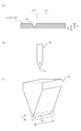
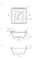
- FIG. 6 An enlarged plan view showing another configuration example of the half cut portion of the food packaging container of FIG. FIG. 2 is a cross-sectional view of the food packaging container taken along line AA in FIG. (A) is an enlarged view of a cross section of a flat portion along the line BB in FIG. 1, (b) is a view showing a blade forming a half-cut portion of (a), (c) It is the perspective view which expanded the blade edge
- (A) And (b) is sectional drawing which shows the other structural example of the fitting structure of the packaging container for foodstuffs of 1st Embodiment of this invention.
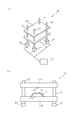
- (A) is a schematic perspective view of the press machine which manufactures the food packaging container of 1st Embodiment of this invention
- (b) is a partial front view of the press machine of (a). It is sectional drawing for demonstrating the usage method of the food packaging container of 1st Embodiment of this invention. It is a top view of the packaging container for foodstuffs of 2nd Embodiment of this invention.
- (A) is a cross-sectional view of the food packaging container along the line CC in FIG.
- (b) is a cross-sectional view showing a state in which the opening portion of the food packaging container of (a) is opened
- (C) is a fragmentary sectional view which shows the other structural example of the cover body of (a). It is an enlarged view of a section around a half cut part of a 2nd embodiment of the present invention.
- (A) And (b) is sectional drawing which shows the other structural example of the operation part of the packaging container for foodstuffs of 2nd Embodiment of this invention. It is sectional drawing for demonstrating the usage method of the food packaging container of 2nd Embodiment of this invention.
- FIG. 4 It is sectional drawing which shows the state which opened the opening part of the packaging container for foodstuffs of (a). It is a schematic perspective view which shows the experiment example of the packaging container for foodstuffs of this invention.
- A) And (b) is the figure which expanded the cross section of the test piece used for the experiment of FIG.
- FIG. 1A is a plan view showing a food packaging container 1 according to the first embodiment of the present invention
- FIG. 2 is a cross-sectional view of the food packaging container 1 along the line AA in FIG. It is.
- the food packaging container 1 includes a container body 10 and a lid 20 that is detachably attached to the container body 10.
- the container main body 10 includes a bottom portion 11, a side surface portion 12 that rises from the periphery of the bottom portion 11, and a flange portion (hereinafter referred to as a main body flange portion 13) that extends outward from the upper end portion of the side surface portion 12. Yes.
- the upper end portion of the side surface portion 12 forms a mouth, and the lid body 20 is attached to the container body 10 so as to close the mouth.
- the lid 20 includes a top surface portion 21, a fitting portion 22 that is provided around the top surface portion 21 and fits into the mouth of the container body 10, and a flange portion that extends outward from the fitting portion 22 to form an edge ( Hereinafter, it is referred to as a lid flange portion 23).
- the top surface portion 21 is formed as a circular region in plan view.
- the top surface portion 21 is formed to be flat throughout, but a part thereof protrudes upward or a part of the top surface part 21 is depressed downward, so that a flat part and a convex part or a concave part are formed. And may be mixed.
- the flat region is referred to as a flat portion 30.
- the lid 20 is provided with an unsealing portion 310 so that a hole is opened by using the flat portion 30 so that a part of the lid 20 is raised or pushed into the bottom of the container body 10.
- FIG. 1B is an enlarged plan view showing the opening part 310.
- the opening portion 310 is provided as a circular region at the center of the flat portion 30, and the opening portion 310 includes a non-cutting portion 311 in which a part of the periphery of the opening portion 310 is seamlessly connected to the surrounding flat portion.
- FIG. 1B illustrates the non-cut portion 311 with a two-dot chain line. Further, the remaining peripheral edge is detachably connected to the surrounding flat portion via the half-cut portion 320, and FIG. 1B represents the half-cut portion 320 with a solid line.
- the half-cut portion 320 includes a cutting edge 61 of the cutting blade 60 shown in FIG. It is a portion having a thickness thinner than that of the periphery, which is stopped halfway so as not to penetrate the flat portion 30 (flat portion) and is formed with a cut 321.
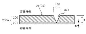
- the thickness t1 of the flat portion 30 and the thickness t2 of the half cut portion 320 are set in the following ranges (1) and (2).
- the thickness t2 is the thickness of the connected portion remaining in the half cut part 320, and is a value measured by the following method.
- the flat portion 30 including the half cut portion 320 is cut with a cutter blade, the cross section of the half cut portion 320 is observed with an optical microscope or the like, and the thickness at the cut portion is measured.
- Such measurement is performed at a plurality of locations of the half-cut portion 320, for example, at three locations, and an average is obtained from the measured values to obtain the thickness t2 of the half-cut portion 320.
- the cut 321 is formed as a straight line in a C shape in plan view, but as shown in FIG. 1 (c), a plurality of cuts 321 and non-cut portions are formed. 315 may be alternately arranged around the opening 310.
- the non-notch portion 315 is provided between two notches 321 adjacent to each other and connects the opening portion 310 and the flat portion around the notch portion 321, is formed without the notch, and is formed so as to be cuttable. Yes.
- the inclined portion 24 extends outward from the periphery of the top surface portion 21 and constitutes a slope that gradually falls from the flat portion 30.
- the fitting portion 22 includes a horizontal portion 22 ⁇ / b> A that extends outward from the lower end of the inclined portion 24, and a folded portion 22 ⁇ / b> B that extends upward from the end and meets the inner surface of the container body 10.
- the lid 20 is not limited to the convex shape that forms the highest portion of the central flat portion 30 as described above, and the flat portion 30 and its surroundings may be changed to other shapes.
- the outer body 231 extends downward from the end of the lid flange 23 as shown in FIG.
- An outer fitting type structure that holds the end of the flange portion 13 is used, or the entire inside of the lid flange portion 23 is configured as a top surface portion 21 (flat portion 30) as shown in FIG.
- An internal / external fitting type structure in which the lid flange portion 23 covers the main body flange portion 13 from the inside to the outside may be used.
- the material of the container body 10 and the lid 20 is not limited, but polyolefin resin, polystyrene resin, or polyester resin can be used.
- the food packaging container 1 of the present embodiment softens a sheet material made of polystyrene, polypropylene (PP), PET, a mixed resin, or the like as a plastic molded product by heat, and further vacuum-forms or pressure-forms it with a mold.
- the food packaging container 1 is transparent and has a haze of 15% or less, preferably 10% or less, more preferably 7% or less as the degree of cloudiness.
- the food packaging container 1 is not limited to having transparency, and may be configured to be opaque.
- the lid 20 and the container body 10 may be integrally configured via a hinge portion.
- Half cut part 320 is formed by the process of processing a plastic molded product after the above-mentioned forming process. In the processing step, it is desirable that the cut 321 is formed by the cutting blade 60 as the half-cut portion 320 and further has the same depth over the entire length.
- a blade having a straightness of preferably within 0.05 / 100L, more preferably within 0.01 / 100L is used.
- straightness will be described with reference to FIG. 3C.
- a cylinder indicated by a two-dot chain line with the cutting edge 61 extending in a straight line as a central axis in the design represents an extension of an allowable error range, and the manufactured cutting edge 61 Is located on or in this surface.
- the range is defined by extending a circular region having a diameter ( ⁇ ) of 0.1 mm and extending the length (L) by 100 mm in a direction perpendicular to the region.
- a cutting blade 60 having a cutting edge extending in an arc shape is used.
- the cutting edge 61 extends in an arc shape, it means that the cutting edge 61 is in a cylinder, and the range is a straight line in which the cutting edge 61 extended in an arc shape in the design is converted into a straight line and the straight line is used as a center axis.
- Length (L) Straightness also represents the tolerance of the cutting edge parallel to the sheet to be cut.
- a 3D scanner can be used for the measurement of such a cutting blade.
- the press machine 50 In the machining process, the press machine maintains the level of the blade edge 61, and a high-precision machine with four-axis independent control is used as the press machine.
- the press machine 50 includes a slide 51A, four shafts 52 that support the slide 51A, four drive units 53 that drive each shaft 52, and a control unit 54.
- the shaft 52 is composed of a ball screw
- the drive unit 53 is composed of a servo motor
- the servo motor rotates the ball screw by the control unit 54.
- Such driving of the shaft 52 is performed independently.
- the number of shafts 52 that support the slide 51A is not limited to four.
- the press machine 50 may include three or more shafts 52, and the control unit 54 may control each shaft 52 individually so that the slide 51A is held horizontally.
- the cutting blade 60 is attached to the slide 51A with a straightness within 0.1 / 100L.
- the cutting blade 60 is C-shaped with a cutting edge 61 extending in an arc shape, and the tip shown in FIG. 3B is formed with a sharp point at an angle ⁇ of 30 ° to 60 °.
- a single blade may be used instead of the double-edged cutting blade 60 shown in FIG.
- the cutting blade 60 is made of a tungsten carbide / cobalt alloy as a cemented carbide. Further, in the press machine 50, the bolster bed plate 51B holds the mold 51C.
- the cutting blade 60 has a high cutting edge linearity accuracy, and uses a carbide blade manufactured by Finetech Co., Ltd. (trade name; Filey blade, cutting edge linearity; 0.003 / 100 L). it can.
- a press machine 50 that can control the parallelism and the bottom dead center with high accuracy is desirable, and it is preferable to use a processing machine (trade name; ZENFormer, 4-axis independent control) manufactured by Electric Discharge Precision Processing Laboratory Co., Ltd. it can.
- the lid 20 is attached in a state where the food product is placed in the food packaging container 1. At this time, the lid 20 is fixed by fitting the fitting portion 22 of the lid 20 into the mouth of the container body 10. The movement of the opening part 310 of the lid 20 is restricted by being connected to the peripheral flat part via the half-cut part 320. In this state, the upper part of the food product is covered with the lid 20 without any gap.
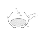
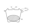
- the half-cut part 320 is cut and the opening part 310 is pushed into the container to open the hole 40 as shown in FIG. 6, for example. Steam generated in the process of heating the food product 80 exits from the hole 40.
- the lid 20 includes the half-cut portion 320 that leaves a predetermined thickness t2 for punching. Unlike the hole which penetrated the lid
- the hole 40 can be easily opened partially only by cutting the connecting portion remaining in the half-cut portion 320.
- the lid 20 can be detachably attached to the container body 10 by the fitting portion 22. Thereby, after taking out a part of heated foodstuff 80 outside, the foodstuff 80 can be covered with the cover body 20 repeatedly.
- FIG. 7 is a plan view of the food packaging container 2 according to the second embodiment of the present invention
- FIG. 8A is a cross-sectional view of the food packaging container 2 taken along the line CC of FIG.
- the food packaging container 2 is composed of a container main body 10A and a lid 20A.
- the lid 20A is a fitting portion. 22 is not provided.
- the lid 20A is configured to be fixed by overlapping the container body 10A and the peripheral portion.
- symbol is used for the same or similar structure as the structure of the food packaging container 1 of 1st Embodiment, and those description is abbreviate
- the flange portions of the container body 10A and the lid body 20A (hereinafter referred to as the body flange portion 13A and the lid flange portion 23A) are formed on a flat surface extending outward so that they can overlap each other.
- the lid 20A is attached to the container main body 10A by being thermally bonded by the sealing machine in the overlapped state.
- the width w of the main body flange portion 13A and the lid flange portion 23A is preferably 3 mm or more.
- the lid body 20A and the container body 10A may be made of a laminated material made up of a plurality of layers in addition to molding and manufacturing the base material 200 made up of a single layer shown in FIG. .
- a laminated material 200 ⁇ / b> A in which a film layer 201 is superimposed on the inside of a base material 200 may be used.
- the film layer 201 functions such as a gas barrier layer, a moisture-proof layer, and a heat seal layer can be added to the substrate 200.
- the weight of the polyolefin resin is desirably 70% or more of the weight of the resin in the entire laminated material.
- the cut 321 of the half cut part 320 reaches the film layer 201, and the thickness t2 of the half cut part 320 is the thickness of the portion remaining in the film layer 201, which is the above (2). Is set in the range.
- the half-cut portion 320 may be formed without making the cut 321 in the film layer 201, or the cut 321 cuts the film layer 201 from the inside of the container to connect only the base 200.
- the half cut part 320 may be configured to remain.
- the cut 321 may cut the gas barrier layer or the like.
- the lid 20A includes a protruding portion 25 protruding upward from the peripheral edge of the flat flat portion 30 at the center, as shown in FIG.
- the projecting portion 25 is provided around the flat portion 30 except for the front side, and these projecting portions 25 are connected to surround the flat portion 30.
- the top portions 251 constituting the highest portion of the projecting portion 25 are configured to have the same height, and slopes extending outward from the top portions 251 extend to the lid flange portion 23A.
- a label application surface 26 is formed on the front side of the flat portion 30.
- the lid 20 ⁇ / b> A may be configured by omitting the label attaching surface 26, or may be provided with a protruding portion 25 so as to surround the entire flat portion 30.
- the operation part 27 for facilitating the hole opening at the time of opening is provided integrally with the area inside the half cut part 320, that is, the flat part 30.
- the operation portion 27 protrudes upward, and its height h is set so as not to exceed the height H of the protruding portion 25.
- the height h from the flat part 30 of the operation part 27 is preferably 5 mm or more.
- the operation unit 27 includes a pair of opposing surfaces 271A and 271B, and is configured so that it can be picked.
- the lid 20A includes an embedded portion 28 that is close to the opening portion 310 and is recessed toward the bottom side of the container body 10A.
- the opening portion 310 is configured to be able to rotate about the non-cutting portion 311 indicated by a two-dot chain line in FIG. 7, and the embedded portion 28 is opened in the direction indicated by the arrow D in FIG. It is provided in the direction in which 310 is rotated, and the operation unit 27 can be inserted.
- the embedding part 28 is configured by selecting a size and a depth so that the operation part 27 can be fitted. As shown in FIG. 8B, the embedding unit 28 can maintain a state where the operation unit 27 is rotated 180 degrees after the operation unit 27 is picked and the hole 40 is opened.
- FIG. 8C is a cross-sectional view showing a modified example of the structure for fixing the operation unit 27, and shows a state in which the operation unit 27 is rotated by 180 degrees.
- the lid 20A may be configured such that a shallow bottom portion 28A for inserting the peripheral region of the opening portion 310 is provided adjacent to the embedded portion 28, and the operation portion 27 is accommodated in the embedded portion 28 and the shallow bottom portion 28A.
- the operation unit 27 is not limited to a configuration that functions as a knob.
- the operation unit 27 is formed in a button shape so that the half-cut unit 320 can be easily cut by pressing. May be.
- the container body 10A and the lid body 20A of the second embodiment are also half-cut into the flat portion 30 using a press machine 50 provided with a cutting blade 60 after molding a resin sheet material.
- the part 320 can be formed and manufactured.
- the protrusion 25, the operation part 27, the embedding part 28, etc. are formed by molding integrally with the flat part 30 at the time of molding, but the protrusion 25, the operation part 27, the embedding part 28, etc. are omitted for food.
- the packaging container 2 may be manufactured.
- the container body 10A and the lid 20A are made of a laminated material having a base material 200 and a heat-sealing seal layer, and the laminated material is mainly made of polypropylene, the outermost layer provided on the outermost side.
- the difference (T1 ⁇ T2) between the melting point T1 of the sealing layer and the melting point T2 of the sealing layer is preferably 10 ° C. or more and less than 50 ° C.
- the lid 20A is attached in a state where the food product is placed in the container body 10A. At this time, the lid body 20A is fixed by joining with the sealing machine in a state where the main body flange portion 13A and the lid flange portion 23A are overlapped.
- the opening part 310 of the lid 20A is connected to the peripheral flat part via the half-cut part 320, so that the movement is restricted. In this state, the upper part of the food product is covered with the lid 20A without any gap.
- the lid 20A When heating food contained in the food packaging container 2 with a microwave oven, the lid 20A is attached to the container body 10A and sealed and placed on the table of the microwave oven. During the process of heating the food product, the pressure inside the food packaging container 2 gradually increases. This pressure acts on the half-cut portion 320 that is weakly formed with the cut 321 in the structure of the food packaging container 2, and the remaining connected portion is cut. Thereby, as shown in FIG. 11, the unsealing part 310 rises from the initial position indicated by the broken line to the high position indicated by the solid line while being pushed by the steam. A hole 40 can be opened in the middle of heating to allow steam to escape. Note that, before heating, the hole 40 may be formed by cutting the half-cut portion 320 as in the first embodiment.
- the main body flange portion 13 ⁇ / b> A and the lid flange portion 23 ⁇ / b> A are heat-sealed, so that the sealing performance can be improved as compared with the first embodiment. Furthermore, since a gas barrier layer can be provided to the food packaging container 2, the sealing property can be further enhanced.
- FIG. 12A and 12B show a food packaging container 3 according to a third embodiment of the present invention, in which FIG. 12A is a plan view and FIG. 12B is a cross-sectional view taken along line EE of FIG.
- the food packaging container 3 is composed of a container body 10B and a lid 20B.
- the unsealing part 310 is a container body 10B. Is provided.
- the container main body 10 ⁇ / b> B is configured as a flat portion 30 while the central region of the bottom portion 11 ⁇ / b> B is provided at a position higher than the peripheral region of the landing.
- the half cut part 320 is formed in the flat part 30 of the bottom part 11B.
- the central region is configured with the thickness t1 of (1) above, and the half-cut portion 320 is formed as a portion leaving the thickness t2 of (2) above.
- symbol is used for the same or similar structure as the food packaging container 1 of said 1st Embodiment, and those description is abbreviate
- the half cut part 320 provided in the bottom part 11B is cut, the opening part 310 is wound as shown in FIG. 12 (c), and the hole 40 is partially opened in the container body 10B. Can do.
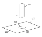
- test condition As shown in FIG. 13, using the test piece 100 provided with a C-shaped half-cut portion 320, the opening degree (opening property) and closing condition (sealing property) of the opening part 310 defined by the half-cut part 320 I confirmed.
- the test piece 100 was manufactured by forming a half-cut portion 320 on a rectangular base material 200 made of plastic using a press machine controlled independently by four axes.
- the cutting blade 60 uses a carbide blade (Finetech Co., Ltd., trade name; Filey blade, linearity of the blade edge; 0.003 / 100 L), and the press machine 50 is a processing machine (Discharge Corporation). Precision Processing Laboratory, trade name: ZENFormer, 4-axis independent control) was used.
- opening portion 310 the opening method of the opening portion 310
- the thickness t2 of the half-cut portion 320 is measured by cutting the test piece 100 and using a cross section of the half-cut portion 320 with an optical microscope (manufactured by KEYENCE; VHX-2000) and a lens (manufactured by KEYENCE; VH-Z100UR). And observed at a magnification of 400 times, and the thickness of the cut portion was measured. The thickness was measured at three locations of the half-cut portion 320, and the average was obtained from each value and handled as the thickness t2 of the half-cut portion 320.
- the half-cut portion 320 has a shape lacking a part of the circumference having a radius of 10 mm in a plan view, and is continuous and has a total length of 47 mm.
- a measuring device manufactured by Instron, electromechanical testing systems, model number 5565
- the end 91 (diameter ⁇ 12 mm) of the movable part 90 is applied to a flat area (opening part 310) inside the half-cut part 320 at a compression speed of 200 mm / Press with min.
- a measurement is complete
- the measuring device measured the maximum value of the peak at that time as opening strength (hereinafter referred to as opening strength) [kg].
- the substrate 200 is made of polypropylene and has a higher melting point on the outside of the container than on the inside of the container, and the overall thickness t1 is 300 ⁇ m.
- the half-cut portion 320 is formed by inserting the cutting blade 60 from the outside of the container, and the thickness t2 is 15 ⁇ m.
- the unsealing strength was 1.7 [kg].
- the opening part 310 whose movement is restricted by the half-cut part 320 can be easily opened, and the state where the movement is restricted by the half-cut part 320 can be stably maintained.
- the overall evaluation of Experimental Example 1 is good ( ⁇ ).
- Experimental Example 2 uses the same specimen 100 as Experimental Example 1, but the opening method is different.
- the unsealing method pressurization of the unsealing portion 310 by the movable portion 90 from the outside of the container was performed as “push” to move the unsealing portion 310 to the inside of the container.
- the opening strength of Experimental Example 2 was 1.7 [kg].
- the opening part 310 whose movement is restricted by the half-cut part 320 can be easily opened, and the state where the movement is restricted by the half-cut part 320 can be stably maintained.
- the overall evaluation of Experimental Example 2 is good ( ⁇ ). From Experimental Example 1 and Experimental Example 2, it was found that handling was not affected by the difference in the opening method.
- Experimental Examples 3 and 4 use the same base material 200 as Experimental Example 1, but the arrangement of the half-cut portions 320 is different.
- the half-cut portion 320 is formed by inserting the cutting blade 60 from the inside of the container, and the thickness t2 is 15 ⁇ m, which is the same as in Experimental Examples 1 and 2. It is.
- the opening method of Experimental Example 3 is “pull”, and the opening method of Experimental Example 4 is “push”.
- the opening strengths of Experimental Example 3 and Experimental Example 4 were 1.7 [kg].
- the opening part 310 whose movement is restricted by the half-cut part 320 can be easily opened, and the state where the movement is restricted by the half-cut part 320 can be stably maintained.
- the comprehensive evaluation of Experimental Example 3 and Experimental Example 4 is good ( ⁇ ). From Experimental Example 1 to Experimental Example 4, it was found that there is no influence on handling depending on whether the surface on which the half-cut portion 320 is provided is the front side or the back side.
- Experimental Example 5 uses the same substrate 200 as Experimental Example 1, but the thickness t2 of the half-cut portion 320 is different. In Experimental Example 5, the thickness t2 is 5 ⁇ m.
- the opening strength of Experimental Example 5 was 0.8 [kg].
- the opening part 310 whose movement is restricted by the half-cut part 320 can be opened more easily than the experimental example 1, but the function of fixing the opening part 310 by the half-cut part 320 is lowered.
- the overall evaluation of Experimental Example 5 is acceptable ( ⁇ ). From Experimental Example 5, it was found that the remaining thickness dimension at the notch was reduced, but there was no significant effect when used for food packaging containers.
- Experimental Example 6 uses the same substrate 200 as Experimental Example 1, but the thickness t2 of the half-cut portion 320 is different. In Experimental Example 6, the thickness t2 is 20 ⁇ m.
- the surface on which the half-cut portion 320 is provided and the opening method are the same as in Experimental Example 1.
- the opening strength of Experimental Example 6 was 2.3 [kg]. Compared with Experimental Example 1, it is necessary to increase the force in the operation of the opening part 310 when making a hole, but the function of fixing the opening part 310 by the half-cut part 320 is enhanced.
- the overall evaluation of Experimental Example 6 is acceptable ( ⁇ ). From Experimental Example 6, it was found that the remaining thickness dimension at the notch was increased, but there was no significant influence when used in a food packaging container.
- Experimental Example 7 utilized a substrate 200 different from Experimental Example 1.
- the base material 200 of Experimental Example 7 is the same as that of Experimental Example 1 as a material, but the entire thickness t1 is 250 ⁇ m.
- the surface on which the half-cut portion 320 is provided, its thickness t2, and the opening method are the same as in Experimental Example 1.
- the opening strength of Experimental Example 7 was 1.7 [kg].
- the opening part 310 whose movement is restricted by the half-cut part 320 can be easily opened, and the state where the movement is restricted by the half-cut part 320 can be stably maintained.
- the overall evaluation of Experimental Example 7 is good ( ⁇ ). From Experimental Example 1 and Experimental Example 7, it was found that there is no influence on the handling due to the difference in the total thickness t1 of the base material 200.
- Experimental Example 8 utilized a substrate 200 different from Experimental Example 1.
- the base material 200 of Experimental Example 8 used a laminated material in which a low-density polyethylene film layer (50 ⁇ m) was provided inside an polypropylene (250 ⁇ m) via an adhesive.
- the thickness t2 of the half cut part 320 is 30 ⁇ m.
- the surface on which the half-cut portion 320 is provided and the opening method are the same as in Experimental Example 1.
- the opening strength of Experimental Example 8 was 3.2 [kg]. Compared with Experimental Example 1, it is necessary to increase the force in the operation of the opening part 310 when making a hole, but the function of fixing the opening part 310 by the half-cut part 320 is enhanced.
- the overall evaluation of Experimental Example 8 is acceptable ( ⁇ ). From Experimental Example 8, it was found that the laminate material was used and the remaining thickness dimension at the notch 321 was increased, but there was no significant influence when used for a food packaging container.
- Experimental Example 9 utilized a substrate 200 different from Experimental Example 1.
- the base material 200 of Experimental Example 9 is made of A-PET and has a thickness t1 of 300 ⁇ m.
- the thickness t2 of the half-cut portion 320, the surface on which the half-cut portion 320 is provided, and the opening method are the same as in Experimental Example 1.
- the opening strength of Experimental Example 9 was 2.5 [kg]. Compared with Experimental Example 1, it is necessary to increase the force in the operation of the opening part 310 when making a hole, but the function of fixing the opening part 310 by the half-cut part 320 is enhanced.
- the overall evaluation of Experimental Example 9 is good ( ⁇ ). From Experimental Example 9, it was found that the difference in the material constituting the substrate 200 had no significant effect when used in a food packaging container.
- Comparative Example 1 uses the same base material 200 as Experimental Example 1, but the thickness t2 of the half-cut portion 320 is different. In Comparative Example 1, the thickness t2 is 0.5 ⁇ m. The opening strength of Comparative Example 1 was 0.1 [kg]. Although it can open very easily compared with Experimental example 1, the function to fix the opening part 310 by the half cut part 320 is inferior. The overall evaluation of Comparative Example 1 is not possible (NG). From Comparative Example 1, the remaining thickness dimension at the notch 321 is 1 ⁇ m or more.
- Comparative Example 2 uses the same base material 200 as Experimental Example 1, but the thickness t2 of the half-cut portion 320 is different. In Comparative Example 2, the thickness t2 is 55 ⁇ m. The opening strength of Comparative Example 2 was 5.2 [kg]. Compared with Experimental Example 1, a large force is required for the operation of the opening part 310 when making a hole. The comprehensive evaluation of Comparative Example 2 is not possible (NG). From Comparative Example 2, the remaining thickness dimension at the notch 321 is preferably 50 ⁇ m or less.
- Table 1 below shows the structure and thicknesses t1 and t2, the blade insertion direction, and the opening method of the base material in the above experimental example.
- Table 2 shows the unsealing strength, unsealing property, sealing property, and comprehensive evaluation of Experimental Examples 1-9 and Comparative Examples 1-2.
- the unsealing property and the sealing property of the unsealing part 310 are half the structure of the flat part 30 (single layer, laminated material) and its thickness t1. It depends on the thickness t2 of the cut part 320.
- the thickness t2 of the half-cut portion 320 is not less than 1 ⁇ m and not more than 50 ⁇ m in the above (2), preferably in the following (3), and more preferably in the range of (4).
- the present invention can be configured without being limited to the above description and illustrated examples.
- the size and shape of the opening portion are not limited to one, and a plurality of opening portions may be provided.
- the material constituting the food packaging container is not limited to the above, and a laminated material in which a resin sheet having a hole and a resin film provided with a half-cut portion 320 overlap each other may be used.
- a region surrounded by the half-cut portion and a hole region are arranged in the thickness direction.
- a laminated body is molded to produce a lid body or a container body, and when used, the remaining connection portion is cut at the half-cut portion 320, and for example, the opening portion 310 of the film is pushed into the hole of the sheet and opened. it can.
Landscapes
- Engineering & Computer Science (AREA)
- Life Sciences & Earth Sciences (AREA)
- Food Science & Technology (AREA)
- Mechanical Engineering (AREA)
- Perforating, Stamping-Out Or Severing By Means Other Than Cutting (AREA)
- Package Specialized In Special Use (AREA)
- Packages (AREA)
Abstract
L'invention concerne un contenant d'emballage d'aliment se présentant sous la forme d'un produit moulé en plastique et dans lequel un trou peut être réalisé. Le contenant est pourvu d'un corps de contenant comportant une ouverture sur le dessus, et d'un corps de couvercle pour couvrir l'ouverture du corps de contenant. Le corps de couvercle est pourvu d'une section plate (30) d'une épaisseur t1 de 150 µm ou plus épaisse et d'une partie de demi-coupe de perçage de trou (320) formée sur la section plate (30). L'épaisseur t2 de la partie de demi-coupe (320) vérifie une condition de (1 µm ≤ épaisseur t2 de la partie de demi-coupe 320 ≤ 50 µm). La partie de demi-coupe (320) est formée en avançant une lame de coupe de haute précision formée sur un coulisseau dans un matériau en feuille tout en réalisant une commande de parallélisme par entraînement indépendant de trois arbres ou plus supportant un coulisseau d'une presse mécanique.
Priority Applications (2)
| Application Number | Priority Date | Filing Date | Title |
|---|---|---|---|
| JP2018552374A JP7364332B2 (ja) | 2016-11-28 | 2016-11-28 | 食品用包装容器の蓋体及び容器本体、並びにこれらの製造方法 |
| PCT/JP2016/085209 WO2018096681A1 (fr) | 2016-11-28 | 2016-11-28 | Contenant d'emballage d'aliment et procédé de fabrication de celui-ci |
Applications Claiming Priority (1)
| Application Number | Priority Date | Filing Date | Title |
|---|---|---|---|
| PCT/JP2016/085209 WO2018096681A1 (fr) | 2016-11-28 | 2016-11-28 | Contenant d'emballage d'aliment et procédé de fabrication de celui-ci |
Publications (1)
| Publication Number | Publication Date |
|---|---|
| WO2018096681A1 true WO2018096681A1 (fr) | 2018-05-31 |
Family
ID=62194951
Family Applications (1)
| Application Number | Title | Priority Date | Filing Date |
|---|---|---|---|
| PCT/JP2016/085209 Ceased WO2018096681A1 (fr) | 2016-11-28 | 2016-11-28 | Contenant d'emballage d'aliment et procédé de fabrication de celui-ci |
Country Status (2)
| Country | Link |
|---|---|
| JP (1) | JP7364332B2 (fr) |
| WO (1) | WO2018096681A1 (fr) |
Cited By (1)
| Publication number | Priority date | Publication date | Assignee | Title |
|---|---|---|---|---|
| JP2021098255A (ja) * | 2019-12-23 | 2021-07-01 | Agc株式会社 | 切断方法、切断装置および積層体 |
Citations (4)
| Publication number | Priority date | Publication date | Assignee | Title |
|---|---|---|---|---|
| JPH0178550U (fr) * | 1987-11-17 | 1989-05-26 | ||
| JPH1179260A (ja) * | 1997-07-17 | 1999-03-23 | Toyo Alum Kk | 内圧開放可能な包装材 |
| WO1999061346A1 (fr) * | 1998-05-27 | 1999-12-02 | Morinaga Milk Industry Co., Ltd. | Materiau d'emballage et contenant destine a conditionner des boissons et des aliments |
| US20140110403A1 (en) * | 2011-05-26 | 2014-04-24 | Amcor Flexibles Transpac B.V.B.A. | Hermetically closed package to be heated in a microwave oven |
Family Cites Families (7)
| Publication number | Priority date | Publication date | Assignee | Title |
|---|---|---|---|---|
| JPS58151594U (ja) * | 1982-04-01 | 1983-10-11 | 六甲バタ−株式会社 | ゲル状食品用合成樹脂製カツプ容器 |
| US4460103A (en) | 1982-07-19 | 1984-07-17 | Alvex Development Corp. | Cover for drink containers |
| JPH0966937A (ja) * | 1995-08-31 | 1997-03-11 | Mitsubishi Plastics Ind Ltd | プラスチック蓋 |
| JPH11147559A (ja) * | 1997-11-11 | 1999-06-02 | Dainippon Printing Co Ltd | 蓋材及びそれを用いた容器 |
| JP4843875B2 (ja) | 2001-03-16 | 2011-12-21 | 大日本印刷株式会社 | 易開封性蓋材およびその製造方法 |
| JP2011173618A (ja) | 2010-02-24 | 2011-09-08 | Osaka Sealing Printing Co Ltd | 包装用フィルム材及び収容容器 |
| JP6532127B2 (ja) | 2014-12-25 | 2019-06-19 | 株式会社放電精密加工研究所 | 電動プレス加工機 |
-
2016
- 2016-11-28 JP JP2018552374A patent/JP7364332B2/ja active Active
- 2016-11-28 WO PCT/JP2016/085209 patent/WO2018096681A1/fr not_active Ceased
Patent Citations (4)
| Publication number | Priority date | Publication date | Assignee | Title |
|---|---|---|---|---|
| JPH0178550U (fr) * | 1987-11-17 | 1989-05-26 | ||
| JPH1179260A (ja) * | 1997-07-17 | 1999-03-23 | Toyo Alum Kk | 内圧開放可能な包装材 |
| WO1999061346A1 (fr) * | 1998-05-27 | 1999-12-02 | Morinaga Milk Industry Co., Ltd. | Materiau d'emballage et contenant destine a conditionner des boissons et des aliments |
| US20140110403A1 (en) * | 2011-05-26 | 2014-04-24 | Amcor Flexibles Transpac B.V.B.A. | Hermetically closed package to be heated in a microwave oven |
Cited By (3)
| Publication number | Priority date | Publication date | Assignee | Title |
|---|---|---|---|---|
| JP2021098255A (ja) * | 2019-12-23 | 2021-07-01 | Agc株式会社 | 切断方法、切断装置および積層体 |
| JP7081581B2 (ja) | 2019-12-23 | 2022-06-07 | Agc株式会社 | 切断方法、切断装置および積層体 |
| TWI797518B (zh) * | 2019-12-23 | 2023-04-01 | 日商Agc股份有限公司 | 切斷方法及切斷裝置 |
Also Published As
| Publication number | Publication date |
|---|---|
| JP7364332B2 (ja) | 2023-10-18 |
| JPWO2018096681A1 (ja) | 2019-06-24 |
Similar Documents
| Publication | Publication Date | Title |
|---|---|---|
| JP2017520488A (ja) | ダイカット蓋および関連付けられた容器および方法 | |
| EP3962820B1 (fr) | Récipient doté d'une couche externe en carton et d'une fine couche interne en feuille plastique | |
| KR20160084435A (ko) | 용기 본체, 용기 및 용기의 제조 방법 | |
| RU2763229C2 (ru) | Устройство и способ изготовления пакетов со сварным швом по периметру | |
| JP2015048095A (ja) | 容器封止構造およびインナーシール材 | |
| WO2020056702A1 (fr) | Emballage de contenant en papier et son procédé de fabrication | |
| JP7364332B2 (ja) | 食品用包装容器の蓋体及び容器本体、並びにこれらの製造方法 | |
| JP2025170148A (ja) | ブランク材、紙製容器および蓋材付き紙製容器 | |
| US10850422B2 (en) | Cutting system, and a method for cutting a web or sheet of material | |
| JP7771594B2 (ja) | トレー容器用ブランク及びトレー容器 | |
| JP6822405B2 (ja) | 紙容器の製造方法 | |
| JP7593137B2 (ja) | 紙製容器および蓋材付き紙製容器 | |
| JP2005298067A (ja) | 基板材料にプラスチックホイルを貼付するためのシーリングユニット | |
| JP6626317B2 (ja) | スパウト付きガゼット袋およびその製造方法 | |
| JP7472740B2 (ja) | トレー容器 | |
| JP7360632B2 (ja) | ブランク材、紙製容器および蓋材付き紙製容器 | |
| KR20190050290A (ko) | 포장체 및 그 제조 방법 | |
| JP2004345686A (ja) | 易開封容器 | |
| JP7456318B2 (ja) | トレー容器 | |
| JP7655088B2 (ja) | 紙製容器、蓋材付き紙製容器およびブランク材 | |
| JP2994864B2 (ja) | 易開封性密封容器 | |
| CA3130702A1 (fr) | Enveloppe pelable a l'epreuve des enfants | |
| JP7437801B2 (ja) | プラスチック容器、及び、プラスチック容器の製造方法 | |
| JP7582017B2 (ja) | ブランク材、紙製容器および蓋材付き紙製容器 | |
| JPS60193836A (ja) | 開口容易な蓋の製造方法 |
Legal Events
| Date | Code | Title | Description |
|---|---|---|---|
| 121 | Ep: the epo has been informed by wipo that ep was designated in this application |
Ref document number: 16922366 Country of ref document: EP Kind code of ref document: A1 |
|
| ENP | Entry into the national phase |
Ref document number: 2018552374 Country of ref document: JP Kind code of ref document: A |
|
| NENP | Non-entry into the national phase |
Ref country code: DE |
|
| 122 | Ep: pct application non-entry in european phase |
Ref document number: 16922366 Country of ref document: EP Kind code of ref document: A1 |