WO2018096687A1 - Ensemble tête d'encre - Google Patents
Ensemble tête d'encre Download PDFInfo
- Publication number
- WO2018096687A1 WO2018096687A1 PCT/JP2016/085229 JP2016085229W WO2018096687A1 WO 2018096687 A1 WO2018096687 A1 WO 2018096687A1 JP 2016085229 W JP2016085229 W JP 2016085229W WO 2018096687 A1 WO2018096687 A1 WO 2018096687A1
- Authority
- WO
- WIPO (PCT)
- Prior art keywords
- ink
- cap
- ink head
- tank
- moisturizing
- Prior art date
- Legal status (The legal status is an assumption and is not a legal conclusion. Google has not performed a legal analysis and makes no representation as to the accuracy of the status listed.)
- Ceased
Links
Images


Classifications
-
- B—PERFORMING OPERATIONS; TRANSPORTING
- B41—PRINTING; LINING MACHINES; TYPEWRITERS; STAMPS
- B41J—TYPEWRITERS; SELECTIVE PRINTING MECHANISMS, i.e. MECHANISMS PRINTING OTHERWISE THAN FROM A FORME; CORRECTION OF TYPOGRAPHICAL ERRORS
- B41J2/00—Typewriters or selective printing mechanisms characterised by the printing or marking process for which they are designed
- B41J2/005—Typewriters or selective printing mechanisms characterised by the printing or marking process for which they are designed characterised by bringing liquid or particles selectively into contact with a printing material
- B41J2/01—Ink jet
- B41J2/135—Nozzles
- B41J2/165—Prevention or detection of nozzle clogging, e.g. cleaning, capping or moistening for nozzles
Definitions
- This application relates to the ink head assembly.
- ink jet printer apparatuses such as ink jet printers and ink jet plotters using an ink jet recording method are known.
- the ink jet recording method prints on a recording medium by ejecting ink, which has been formed into fine droplets, from a nozzle hole of a head toward a recording medium such as paper.
- Inkjet printers are also required to increase the printing speed, but the printing speed is slow in the method of printing by scanning an ink head (also called an inkjet head) in the width direction of the recording medium.
- an ink jet which uses a fixed ink head in which a plurality of nozzle holes are arranged in the width direction of the recording medium and simultaneously prints the lines in the width direction of the recording medium to increase the printing speed.
- Type printer device For example, an ink jet printer apparatus that performs printing on a continuous printing sheet, which is a recording medium, using a fixed ink head has been put to practical use as a line printer apparatus.
- the ink head is divided into several parts and combined to form an ink head assembly. ing. Specifically, the printing paper is divided into a plurality of areas in the width direction, and a small ink head is prepared for each divided area to share printing.
- the ink head assembly is formed by arranging a plurality of ink heads, for example, in a staggered manner in two rows on a frame at a position facing the printing paper.
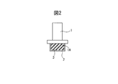
- the ink head 1 is provided with a cap 2 that prevents the ink from drying when not in use and covers the nozzle surface 1 ⁇ / b> A of the ink head 1 to keep the ink moisturized.
- the cap 2 that covers the nozzle surface 1A of the ink head 1 is obstructed during printing, and is retracted, and is then placed over the ink head 1 at the end of printing.
- the ink of the ink jet printer is often water-based ink, and the moisture retaining pad 3 is made of a porous material that is a water-absorbing member, and the sealing liquid is lubricated.
- the moisturizing pad 3 since the moisturizing pad 3 directly hits the nozzle surface 1A, it is possible to prevent the ink from drying from the moment it hits, but a mechanism for constantly moistening the moisturizing pad 3 so as not to dry is necessary.
- the mechanism of constantly moistening with the sealing liquid so that the moisturizing pad of the comparative technique does not dry is provided with a sealing liquid reservoir beside the moisturizing pad provided in the cap, and the sealing liquid is transferred from the sealing liquid reservoir to the moisturizing pad. It was a simple structure to supply. For this reason, the ink drying prevention device that supplies the sealing liquid to the moisture retaining pad of the comparative technique has a problem that the sealing liquid is not sufficiently supplied in the long term and is not highly reliable for industrial use.
- an object of the present application is to provide an ink head assembly including a reliable ink drying prevention device capable of supplying a sealing liquid to a moisture retention pad for preventing drying of the ink head for a long period of time.
- an ink tank that supplies ink to the ink head, a cap that covers the nozzle surface of the ink head when not printing, and a nozzle surface that is disposed in the cap and covers the nozzle surface when the cap is covered by the nozzle surface
- a water-absorbing moisture-retaining pad that touches the nozzle surface
- a liquid level adjusting device that raises the liquid level of the ink stored in the ink tank by a predetermined height above the inner bottom of the cap when the cap is placed on the nozzle surface.
- the cap that covers the nozzle surface of the ink head during non-printing, the water-absorbing moisture-retaining pad that is disposed in the cap and contacts the nozzle surface when the cap is placed on the nozzle surface, and the cap So that the level of the moisturizing liquid tank that stores the moisturizing liquid to be supplied into the cap and the level of the moisturizing liquid that accumulates in the cap is higher than the inner bottom of the cap by a predetermined height.
- An ink head assembly including a moisturizing liquid supply device that supplies moisturizing liquid to a cap is provided.
- an ink head assembly including a highly reliable ink drying prevention device capable of supplying a sealing liquid to a moisture retaining pad for preventing drying of the ink head for a long period of time is provided.
- FIG. 1 is a side view showing a state in which a cap for drying prevention is attached to an ink head assembly of a comparative technique.
- FIG. 2 is a side view including a partial cross section in a state in which a drying prevention cap having a moisture retention pad is attached to an ink head assembly of a comparative technique.
- FIG. 3A is a side cross-sectional view showing a state in which a moisture retention pad built-in cap is in contact with the ink head.
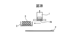
- FIG. 3B is a side cross-sectional view illustrating a state in which the cap with a moisturizing pad is retracted from the ink head.
- FIG. 3C is a side cross-sectional view illustrating a state where the ink head performs printing in a state in which the cap with a moisturizing pad is retracted from the ink head.
- FIG. 4 is a partial perspective view showing a moisturizing pad retracting mechanism in an inkjet line printer.
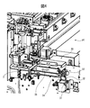
- FIG. 5 is a partial perspective view showing a state in which the ink head lifting mechanism in the inkjet line printer has lifted the ink head.
- FIG. 6 is a partial perspective view showing a state in which the ink head lifting mechanism in the inkjet line printer lowers the ink head.
- FIG. 7A is a schematic diagram illustrating a first example of the first form of the disclosed ink head assembly.
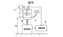
- FIG. 7B is a schematic diagram illustrating a modification of the first example of the first mode of the disclosed ink head assembly.
- FIG. 8 is a partial perspective view showing a specific structure of the first form of the disclosed ink head assembly in an inkjet line printer.
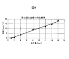
- FIG. 9 is a graph showing the liquid level difference between the liquid level of the cap and the liquid level of the ink tank and the measurement result of the flow rate.
- FIG. 10A is a schematic diagram illustrating a second example of the first form of the disclosed ink head assembly.
- FIG. 10B is a schematic diagram illustrating a modification of the second embodiment of the first form of the disclosed ink head assembly.
- FIG. 11 is a schematic view showing a first example of the second mode of the disclosed ink head assembly.
- FIG. 12A is a partially enlarged perspective view illustrating an example of connection between the cap and the moisturizing liquid supply pipe illustrated in FIG. 11.
- 12B is a cross-sectional view taken along line AA in FIG. 12A.
- FIG. 13 is a partial perspective view showing a specific structure of the first example of the second form of the disclosed ink head assembly in an inkjet line printer.
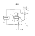
- FIG. 14 is a schematic view showing a second embodiment of the second form of the disclosed ink head assembly.
- an inkjet line printer that performs printing on continuous paper will be described as an example of a printing apparatus equipped with an ink head assembly.
- a printing apparatus that can be equipped with the ink head assembly according to the present application is an inkjet printing apparatus. It is not limited to a line printer of the type. Further, what is to be printed is not limited to continuous paper, but may be cut paper, cardboard, cloth, or the like.
- FIGS. 3A to 3C Before explaining the disclosed inkjet assembly, an example of the operation of a cap incorporating a moisture retention pad in a general inkjet line printer will be described with reference to FIGS. 3A to 3C.
- a device that covers the ink head when the printer is not printing and retracts the cap when printing will be described with reference to FIGS.
- the ink used by the ink jet type line printer is water-based ink will be described.
- FIG. 3A shows a state in which the moisturizing pad 3 arranged on the cap 2 is in contact with the nozzle surface 1A of the ink head 1.
- a moisturizing liquid 7 (which may be ink), which will be described later, is accumulated on the inner bottom of the cap 2, and the moisturizing pad 3 is moistened. Since the ink nozzle 1N provided on the nozzle surface 1A of the ink head 1 is in contact with the moisturizing pad 3, drying of the ink is prevented.
- a symbol P indicates a sheet to be printed (printed) by the ink head 1.
- FIG. 3B shows the operation of the ink head 1 and the cap 2 when the ink head 1 shifts to a printing state.
- the ink head 1 is slightly raised from the position shown in FIG. 3A, and then the cap 2 is moved to the retracted position. Then, with the cap 2 retracted to the retracted position, as shown in FIG. 3C, the ink head 1 is lowered to the position of the sheet P, and ink is ejected from the nozzles 1N, whereby printing is performed on the sheet P. .
- FIG. 4 shows the moisture retention pad retracting device 30 in the inkjet line printer PT.
- the first pulley 33 rotates due to the movement of the first belt 32 stretched around the drive shaft (not shown) of the motor 31.
- the second pulley 34 provided coaxially with the first pulley 33 rotates, and the second belt 35 stretched over the second pulley 34 moves to move the cap 2 in the retracted position. Move up.
- the motor 31 may be reversed.
- the moisturizing pad retracting device 30 in the line printer PT described in FIG. 4 moves the cap 2 in the horizontal direction to retract to the retracted position, but the retracted position of the cap 2 is as shown in FIG. It may be directly under the ink head.
- printer PT shown in FIG. 5 five ink heads 1 are mounted on the ink head assembly ASSY. Since the five ink heads 1 have attachment portions to the base plate 41, they cannot be arranged in a line in a straight line, but are arranged in two lines in a staggered manner.
- the printer PT is provided with an ink head lifting device 40 in the ink head assembly ASSY. When the printer PT is not printing, the ink head assembly ASSY is pulled up by the ink head lifting device 40, and the sheet is removed from directly below the ink head assembly ASSY.
- the moisturizing pad 3 is disposed directly below the five ink heads 1 corresponding to the five ink heads 1 and exposed when the paper is removed from directly below the ink head assembly ASSY. In this state, when the ink head assembly ASSY is lowered by the ink head lifting / lowering device 40, as shown in FIG. 6, the moisturizing pad 3 comes into contact with each ink head 1, and the ink head 1 is prevented from drying.
- the ink head assembly ASSY in the line printer PT shown in FIG. 6 is an example different from the ink head assembly ASSY in the line printer PT shown in FIG. 5, and the number of ink heads 1 is four.
- FIG. 7A discloses the main part of the first embodiment of the ink head assembly ASSY 1 of the first form to be disclosed, and shows a non-printing state of the printer.
- the printer mounting the ink head assembly ASSY1 is not shown, but the installation surface G of the printer is shown.
- the ink head assembly ASSY 1 of the first embodiment includes an ink tank 4 that supplies ink 5 to the ink head 1 of the printer, and a cap 2 that covers the nozzle surface 1A of the ink head 1 when the printer is in a non-printing state.
- FIG. 7A shows the non-printing state of the printer as described above, so that the cap 2 is put on the nozzle surface 1A of the ink head 1.
- a porous moisturizing pad 3 is provided inside the cap 2 as a pad having water absorbability that comes into contact with the nozzle surface 1A when the cap 2 is put on the nozzle surface 1A.
- the height H2 of the bottom surface 2B of the cap 2 from the printer installation surface G when it is placed on the nozzle surface 1A is constant and is a known value. Further, it is assumed that the ink 5 is accumulated in the cap 2 from the bottom surface 2B to the position of the height h2.
- the tube 14 is connected to the bottom of the ink tank 4, and the other end of the tube 14 is connected to the top of the ink head 1.
- Ink 5 can be supplied.
- the tube 14 is formed of a flexible material because the ink tank 4 moves up and down as will be described later.
- the ink 5 is stored in the ink tank 4 by a predetermined height h4.
- the height (liquid level) h4 of the ink 5 in the ink tank 4 is a liquid level sensor 11 provided on the inner wall surface of the ink tank 4.
- the detected value of the liquid level is sent to the control device 50.
- the ink tank 4 is connected to the ink supply source 13 by an ink supplement pipe 17 having a pump 12.
- the control device 50 When the liquid level h4 of the ink 5 in the ink tank 4 becomes low, the control device 50 operates the pump 12 to inject the ink stored in the ink supply source 13 into the ink tank 4.
- Reference numeral 15 denotes an atmosphere opening port of the ink tank 4.
- the liquid level T of the ink 5 in the ink tank 4 (height from the printer installation surface G (H4 + h4)) is the level C of the ink 5 accumulated in the cap 2 (height from the printer installation surface G (H2 + h2)). )),
- the ink 5 flows through the tube 14 to the cap 2.
- the wall thickness of the cap 2 and the ink tank 4 is not considered.
- the ink 5 that has flowed into the cap 2 soaks into the moisturizing pad 3, and excess ink 5 passes through the moisturizing pad 3 and accumulates on the inner bottom of the cap 2. As shown in FIG.
- the cap 2 has a moisturizing liquid having a viscosity lower than that of the ink 5 and the ink 5.
- the liquid level difference H is large, the distribution of the ink 5 is increased and the viscosity is increased. Will be damaged. In addition, useless ink 5 is consumed, and the running cost increases. Therefore, it is better that the liquid level difference H is small.
- the liquid level difference H is negative, that is, the liquid level T of the ink tank 4 is lower than the liquid level C of the ink 5 accumulated in the cap 2, the nozzle of the ink head 1 sucks the liquid of the moisturizing pad 3, This liquid enters a siphon state where it flows into the ink tank 4.
- the moisturizing pad 3 may become dirty due to the dirt of the ink head 1 being moved. In this case, the nozzle of the ink head 1 sucks the dirt, so the liquid level difference H should not be negative.
- the liquid level difference H should be larger than 1 mm.
- the liquid level difference H is preferably about 2 mm considering that the accuracy is about 0.5 mm.
- the liquid level difference H may be smaller than 2 mm, but the apparatus cost increases.
- the liquid level difference H is 2 mm, the liquid volume is 1 mL / H from the graph of FIG. 9, and no adverse effect is exerted on the liquid volume of about 100 mL in the cap 2, and the ink consumption affects the running cost. It's not about.
- an elevating device 10B capable of changing the height H4 of the ink tank 4 from the printer installation surface G is provided as the liquid level adjusting device 10 on the bottom surface of the ink tank 4.
- the liquid level sensor 11 that detects the liquid level T of the ink 5 in the ink tank 4 is provided on the inner wall surface of the ink tank 4, and the detected value is input to the control device 50.
- the control device 50 performs opening / closing control of the pump 12 and raising / lowering control of the ink tank 4 by the lifting / lowering device 10 ⁇ / b> B, whereby the liquid level T of the ink 5 in the ink tank 4 and the liquid level C of the ink 5 accumulated in the cap 2.
- the liquid level difference H can always be maintained at about 2 mm. Since the ink tank 4 moves up and down, the tube 14 is formed of a flexible material so that it can follow the movement of the ink tank 4.
- FIG. 7B shows a modification of the first embodiment of the ink head assembly ASSY1 of the first mode of disclosure, and a part of the first embodiment is described.
- the position of the liquid level sensor 11 is different from that of the first embodiment.
- the liquid level sensor 11 is provided on the inner wall surface of the ink tank 4, but in the modification of the first embodiment, a float switch is used as the liquid level sensor 11.
- the float switch for example, a float switch manufactured by Watty Corporation can be used, and the liquid level T of the ink 5 is detected at the position of the float. Since the other structure is the same as that of the first embodiment, further explanation is omitted.
- various types such as an electrode type, an ultrasonic type, and a capacitance type can be used as the liquid level sensor.
- FIG. 8 is a partial perspective view showing a specific structural example of the ink head assembly ASSY1 of the first embodiment in the ink jet type line printer.
- the ink tank 4 is a tank different from a main tank (not shown) that supplies ink for printing to the ink head 1, and is a sub tank. 4 may be described.
- a symbol T indicates the liquid level of the ink in the sub tank 4.
- Five tubes 14 are connected to the sub tank 4, and each of the five tubes 14 is connected to the ink head 1.
- the sub tank 4 is moved up and down by the sub tank lifting device 10B so that when the cap (not shown) is put on the ink head 1, the ink level difference is about 2 mm.
- the ink tank 4 does not have an ink replenishment tube, and when the ink in the ink tank 4 is reduced, the ink is added or the ink tank 4 is replaced.
- FIG. 10A shows a second embodiment of the ink head assembly ASSY1 according to the first form of the disclosure.
- the height H2 of the bottom surface 2B of the cap 2 from the printer installation surface G when it is placed on the nozzle surface 1A is constant and is a known value, as in the first embodiment.
- the ink tank 4 is provided in parallel with the cap 2 when it is put on the nozzle surface 1A, and the height H4 from the installation surface G of the printer is constant, which is known. It is the value of and does not change.
- the liquid level T of the ink 5 in the ink tank 4 is a predetermined value than the liquid level C of the ink 5 accumulated in the cap 2 when it is put on the nozzle surface 1A.
- the ink tank 4 is arranged so as to be higher only.
- the other end of the tube 14 connected to the bottom surface of the second embodiment of the first embodiment of the ink head assembly ASSY 1 is connected to the top of the ink head 1 so that the ink 5 can be supplied to the ink head 1. . Since the position of the ink tank 4 is fixed, the material forming the tube 14 may not be a flexible material.
- the ink tank 4 is provided with an ink inflow amount adjusting device 10A as the liquid level adjusting device 10, and the amount of ink 5 in the ink tank 4 is adjusted by the ink inflow amount adjusting device 10A.
- the ink inflow adjustment device 10 ⁇ / b> A includes an ink supplement pipe 17 that connects the ink tank 4 and the ink supply source 13, and an electromagnetic opening / closing valve 18 that is provided in the middle of the ink supplement pipe 17. When the electromagnetic opening / closing valve 18 is opened, the ink stored in the ink supply source 13 is injected into the ink tank 4.
- Reference numeral 15 denotes an atmosphere opening port of the ink tank 4.
- the liquid level T indicating the height of the ink 5 in the ink tank 4 is detected by a liquid level sensor (float switch) 11 provided on the ceiling surface of the ink tank T, and the detected value of the liquid level is sent to the control device 50. Sent out.
- the control device 50 takes into account the height of the ink tank 4 from the printer installation surface G and the height from the bottom surface of the ink tank 4 to the liquid level sensor 11, and the printer 5 installation surface of the ink 5 in the ink tank 4. The height from G is calculated. Then, the control device 50 determines the liquid level T, which is the height of the ink 5 in the ink tank 4 from the printer installation surface G, and the height liquid level of the ink 5 accumulated in the cap 2 from the printer installation surface G.
- the electromagnetic on-off valve 18 is controlled to open and close so that the difference H from C is about 2 mm.
- FIG. 10B shows a modification of the second embodiment of the ink head assembly ASSY1 according to the first mode of disclosure, and shows a part of the second embodiment.
- the position of the liquid level sensor 11 is different from that of the second embodiment.
- the liquid level sensor 11 is provided on the ceiling surface of the ink tank 4 to detect the liquid level T of the ink 5.
- the liquid level sensor 11 is It is provided on the inner wall surface of the ink tank 4. Since the other structure is the same as that of the second embodiment, further explanation is omitted.
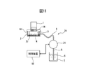
- FIG. 11 shows a first example of the ink head assembly ASSY2 of the second mode of disclosure.
- the first embodiment of the ink head assembly ASSY 2 of the second form there is a cap 2 that covers the nozzle surface 1A of the ink head 1 during non-printing, and the cap 2 has a porous contact with the nozzle surface 1A.
- the moisturizing pad 3 is arranged.
- the ink head assembly ASSY2, which is the first embodiment of the second mode, is provided with a moisturizing liquid supply device 20 that prevents ink from drying on the nozzle surface 1A of the ink head 1 during non-printing.
- the moisturizing liquid supply device 20 includes a moisturizing liquid supply pipe 8 that connects the moisturizing liquid tank 6 that stores the moisturizing liquid 7 and the cap 2, and the moisturizing liquid supply pipe 8 includes the moisturizing liquid in the moisturizing liquid tank 6.
- a pump 21 is provided for taking 7 into and out of the cap 2.
- the moisturizing liquid supply pipe 8 provided between the pump 21 and the moisturizing liquid tank 6 may not be a flexible member, but the moisturizing liquid supply pipe 8 provided between the pump 21 and the cap 2 may be a cap. Since 2 moves, it is formed of a flexible member.
- a tip portion located inside the cap 2 of the moisturizing liquid supply pipe 8 opens in the vicinity of the inner bottom 2 b of the cap 2. It is assumed that the pump 21 can measure the flow rate of the moisturizing liquid 7 flowing through the moisturizing liquid supply pipe 8.
- the moisturizing liquid supply device 20 shown in FIG. 11 is advantageous when the moisturizing liquid tank 6 is located at a position lower than the position of the cap 2 when the cap 2 is placed on the nozzle surface 1A.
- the moisturizing liquid supply device 20 is configured so that when the cap 2 is placed on the nozzle surface 1A, the liquid level N of the moisturizing liquid 7 accumulated in the cap 2 is higher than the inner bottom 2b of the cap 2 by a predetermined height.
- the moisturizing liquid 7 is supplied to the cap 2 by the pump 21.
- the liquid level N of the moisturizing liquid 7 accumulated in the cap 2 can be estimated from the flow rate of the moisturizing liquid 7 supplied to the cap 2.
- 11 shows an example in which the pump 21 is driven by the control device 50, but the control device 50 may not be provided as long as the pump 21 includes the control device.
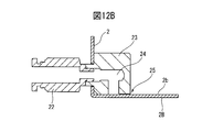
- FIG. 12A shows an example of the connection between the cap 2 and the moisturizing liquid supply pipe 8 shown in FIG. 11, and the moisturizing pad is removed.
- FIG. 12B shows a cross section taken along line AA of FIG. 12A.
- a tube joint 22 and an elbow 23 are provided at a connection portion between the cap 2 and the moisturizing liquid supply pipe 8.
- the tube joint 22 is fitted and connected to the elbow 23.
- the elbow 23 is attached to the inner side surface of the cap 2, and a hole 24 that bends at a right angle is provided inside. There is a slight gap 25 between the surface of the elbow 23 where the hole 24 opens and the bottom surface of the cap 2 through which the moisturizing liquid flows.
- the tube joint 22 and the elbow 23 may be made of metal.
- the moisturizing liquid 7 can be formed by adding a preservative or a surfactant to water.
- the viscosity of the moisturizing liquid is increased by getting wet with ink leaking from the ink head 1, and the viscosity of the moisturizing liquid is further increased because it is dried from the upper surface.
- the ink has a higher viscosity than water and has a viscosity of 4 mPa ⁇ s or more. Further, the viscosity increases by drying, but the moisturizing liquid 7 has a low viscosity of 1 mPa ⁇ s close to that of water. The liquid 7 is absorbed, and an increase in viscosity can be prevented.
- the moisturizing liquid 7 contained in the moisturizing liquid tank 6 is pumped up by the pump 21, injected into the cap 2, and then returned to the moisturizing liquid tank 6 after a predetermined time.
- the pumping and discharging operation of the moisturizing liquid 7 from the moisturizing liquid tank 6 is periodically repeated to maintain the inside of the cap 2 at a low viscosity.
- the moisturizing liquid tank 6 containing the moisturizing liquid 7 is periodically replaced as a consumable item. Thereby, drying of the ink in the nozzle 1N of the ink head 1 can be prevented for a long time.
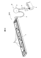
- FIG. 13 shows a specific structure of the moisturizing liquid supply device 20 attached to the ASSY 2 of the first embodiment of the second form of the disclosed ink head assembly in an inkjet line printer.
- the cap 2 is a large one on which five moisturizing pads 3 can be placed on the bottom surface, and the common bottom surface is connected to the moisturizing liquid tank 6 via the pump 21 by the moisturizing liquid supply pipe 8.
- the number of caps 2 can be reduced to one.
- FIG. 14 shows a second embodiment of ASSY2 of the ink head assembly of the second mode of disclosure.
- the second embodiment of the ink head assembly ASSY 2 of the second form there is a cap 2 that covers the nozzle surface 1A of the ink head 1 during non-printing, and the cap 2 has a porous contact with the nozzle surface 1A.
- a moisturizing pad 3 is arranged.
- the ink head assembly ASSY2, which is the first embodiment of the second mode, is provided with a moisturizing liquid supply device 20A that prevents ink from drying on the nozzle surface 1A of the ink head 1 during non-printing.
- the position of the moisturizing liquid tank 6 for storing the moisturizing liquid 7 is higher than the position of the cap 2 when the nozzle surface 1A of the ink head 1 is covered. Therefore, a first electromagnetic opening / closing valve 26 is provided in the middle of the moisturizing liquid supply pipe 8 that connects the moisturizing liquid tank 6 and the cap 2.
- a moisturizing liquid discharge pipe 9 for discharging the moisturizing liquid 7 is provided on the bottom surface of the cap 2, and a second electromagnetic opening / closing valve 27 is provided in the middle of the moisturizing liquid discharge pipe 9.
- the moisturizing liquid 7 flowing out from the cap 2 when the second electromagnetic opening / closing valve 27 is opened is recovered in the moisturizing liquid recovery tank 28.
- the moisturizing liquid supply pipe 8 and the moisturizing liquid discharge pipe 9 are formed of flexible members because the cap 2 moves.
- a liquid level sensor 11 is provided on the side surface of the cap 2 to detect the liquid level of the moisturizing liquid 7 in the cap 2.
- the liquid level of the moisturizing liquid 7 detected by the liquid level sensor 11 is output to the control device 50, and the control apparatus 50 makes the liquid level of the moisturizing liquid in the cap 2 appropriate by the output from the liquid level sensor 11.
- the first electromagnetic opening / closing valve 26 is opened / closed.
- the moisturizing liquid 7 contained in the moisturizing liquid tank 6 is pumped by the pump 21 and injected into the cap 2, and a predetermined time later. The work of returning to the moisturizing liquid tank 6 was periodically repeated.
- the control device 50 periodically opens the second electromagnetic on-off valve 27 to collect the moisturizing liquid 7 in the cap 2 in the moisturizing liquid collection tank 28, and then the second The electromagnetic on / off valve 27 may be closed and the first electromagnetic on / off valve 26 may be opened.
- the moisturizing liquid 7 in the cap 2 can be maintained to have a low viscosity.
- the moisturizing liquid tank 6 containing the moisturizing liquid 7 and the moisturizing liquid recovery tank 28 are periodically replaced as consumables.
- the moisturizing pad built in the cap that covers the nozzle surface of the ink head during non-printing can be maintained in an appropriate state for a long period of time. You can continue printing. Further, the ink head assembly of the present application is not limited to the disclosed embodiments.
Landscapes
- Ink Jet (AREA)
Abstract
La présente invention porte sur un ensemble tête d'encre dans lequel une surface de buse d'une tête d'encre est recouverte d'un capuchon pour empêcher le séchage de l'encre pendant une période de non-impression d'un appareil d'impression. Le capuchon possède un tampon poreux retenant l'humidité et disposé à l'intérieur de celui-ci, ledit tampon entrant en contact avec la surface de buse lorsque la surface de buse est recouverte du capuchon. Un liquide d'étanchéité, destiné à tremper une partie inférieure du tampon retenant l'humidité, est accumulé dans le fond interne du capuchon. Une différence de niveaux, entre le niveau de liquide d'un réservoir d'encre qui fournit de l'encre à la tête d'encre par rapport à une surface d'installation de l'appareil d'impression et le niveau du liquide d'étanchéité par rapport à la surface d'installation de l'appareil d'impression, est établie entre 0 à 2 mm de façon à empêcher de façon permanente le séchage de l'encre dans la surface de buse de la tête d'encre.
Priority Applications (1)
| Application Number | Priority Date | Filing Date | Title |
|---|---|---|---|
| PCT/JP2016/085229 WO2018096687A1 (fr) | 2016-11-28 | 2016-11-28 | Ensemble tête d'encre |
Applications Claiming Priority (1)
| Application Number | Priority Date | Filing Date | Title |
|---|---|---|---|
| PCT/JP2016/085229 WO2018096687A1 (fr) | 2016-11-28 | 2016-11-28 | Ensemble tête d'encre |
Publications (1)
| Publication Number | Publication Date |
|---|---|
| WO2018096687A1 true WO2018096687A1 (fr) | 2018-05-31 |
Family
ID=62195691
Family Applications (1)
| Application Number | Title | Priority Date | Filing Date |
|---|---|---|---|
| PCT/JP2016/085229 Ceased WO2018096687A1 (fr) | 2016-11-28 | 2016-11-28 | Ensemble tête d'encre |
Country Status (1)
| Country | Link |
|---|---|
| WO (1) | WO2018096687A1 (fr) |
Cited By (2)
| Publication number | Priority date | Publication date | Assignee | Title |
|---|---|---|---|---|
| CN115871339A (zh) * | 2021-09-30 | 2023-03-31 | 苏州锐发打印技术有限公司 | 喷墨打印头保湿装置及方法 |
| US20230241892A1 (en) * | 2022-01-31 | 2023-08-03 | Jun Ichinowatari | Liquid discharge apparatus |
Citations (7)
| Publication number | Priority date | Publication date | Assignee | Title |
|---|---|---|---|---|
| JP2002160378A (ja) * | 2000-11-24 | 2002-06-04 | Fuji Xerox Co Ltd | インク乾燥防止装置、インクジェット記録ヘッド保管容器、インクジェット記録装置及びシール液体供給方法 |
| JP2004209897A (ja) * | 2003-01-08 | 2004-07-29 | Ricoh Co Ltd | インクジェット記録装置 |
| JP2010000709A (ja) * | 2008-06-20 | 2010-01-07 | Riso Kagaku Corp | インクジェット記録装置 |
| JP2010120266A (ja) * | 2008-11-19 | 2010-06-03 | Ricoh Co Ltd | 画像形成装置 |
| JP2012121334A (ja) * | 2012-03-29 | 2012-06-28 | Seiko Epson Corp | 流体噴射装置 |
| JP2012158071A (ja) * | 2011-01-31 | 2012-08-23 | Brother Industries Ltd | 液体吐出装置 |
| JP2014180861A (ja) * | 2013-03-21 | 2014-09-29 | Fujifilm Corp | 液体吐出装置及び液体吐出ヘッドの保湿方法 |
-
2016
- 2016-11-28 WO PCT/JP2016/085229 patent/WO2018096687A1/fr not_active Ceased
Patent Citations (7)
| Publication number | Priority date | Publication date | Assignee | Title |
|---|---|---|---|---|
| JP2002160378A (ja) * | 2000-11-24 | 2002-06-04 | Fuji Xerox Co Ltd | インク乾燥防止装置、インクジェット記録ヘッド保管容器、インクジェット記録装置及びシール液体供給方法 |
| JP2004209897A (ja) * | 2003-01-08 | 2004-07-29 | Ricoh Co Ltd | インクジェット記録装置 |
| JP2010000709A (ja) * | 2008-06-20 | 2010-01-07 | Riso Kagaku Corp | インクジェット記録装置 |
| JP2010120266A (ja) * | 2008-11-19 | 2010-06-03 | Ricoh Co Ltd | 画像形成装置 |
| JP2012158071A (ja) * | 2011-01-31 | 2012-08-23 | Brother Industries Ltd | 液体吐出装置 |
| JP2012121334A (ja) * | 2012-03-29 | 2012-06-28 | Seiko Epson Corp | 流体噴射装置 |
| JP2014180861A (ja) * | 2013-03-21 | 2014-09-29 | Fujifilm Corp | 液体吐出装置及び液体吐出ヘッドの保湿方法 |
Cited By (3)
| Publication number | Priority date | Publication date | Assignee | Title |
|---|---|---|---|---|
| CN115871339A (zh) * | 2021-09-30 | 2023-03-31 | 苏州锐发打印技术有限公司 | 喷墨打印头保湿装置及方法 |
| US20230241892A1 (en) * | 2022-01-31 | 2023-08-03 | Jun Ichinowatari | Liquid discharge apparatus |
| US12202269B2 (en) * | 2022-01-31 | 2025-01-21 | Ricoh Company, Ltd. | Liquid discharge apparatus |
Similar Documents
| Publication | Publication Date | Title |
|---|---|---|
| JP5269929B2 (ja) | ノズル面清掃装置及びインクジェット記録装置 | |
| JP5277506B2 (ja) | インクジェット記録ヘッド、インク貯留装置 | |
| US20090109257A1 (en) | Fluid ejecting apparatus | |
| JP5889159B2 (ja) | インクジェットヘッドの清掃装置及び清掃方法、並びにインクジェット記録装置 | |
| KR20100081555A (ko) | 잉크젯 프린터의 노즐 캡핑장치 | |
| JP4070996B2 (ja) | インクジェット記録装置 | |
| US8870315B2 (en) | Image forming apparatus feeding ink in coping with change of ink viscosity and control method for same | |
| EP2465683A1 (fr) | Appareil d'éjection de liquide et programme de stockage de support de stockage | |
| JP2013031962A (ja) | ノズル面清掃装置 | |
| JP6044078B2 (ja) | 印刷装置、及び、湿潤液供給方法 | |
| JP2018154078A (ja) | インクジェット記録装置 | |
| JP2010162791A (ja) | 画像形成装置 | |
| JP5168031B2 (ja) | 液体吐出装置及びこれを備えた画像形成装置 | |
| JP2015231729A (ja) | インクジェットプリンター | |
| WO2018096687A1 (fr) | Ensemble tête d'encre | |
| JP6167730B2 (ja) | 画像形成装置 | |
| US8814321B2 (en) | Liquid ejection apparatus | |
| US20220297441A1 (en) | Printing device and back pressure control method | |
| JP2013159007A (ja) | 印刷装置、及び、ワイピング方法 | |
| JP2015112758A (ja) | 液体噴射装置、及び液体充填方法 | |
| JP2011088345A (ja) | 液体噴射装置 | |
| JP6722559B2 (ja) | インクジェットプリンタのクリーニング部およびインクジェットプリンタ | |
| JP6847982B2 (ja) | 液体吐出ヘッド及び液体吐出装置 | |
| JP2015098134A (ja) | 画像形成装置 | |
| JP2024128935A (ja) | 保湿装置およびインクジェットプリンタ |
Legal Events
| Date | Code | Title | Description |
|---|---|---|---|
| 121 | Ep: the epo has been informed by wipo that ep was designated in this application |
Ref document number: 16922474 Country of ref document: EP Kind code of ref document: A1 |
|
| NENP | Non-entry into the national phase |
Ref country code: DE |
|
| 122 | Ep: pct application non-entry in european phase |
Ref document number: 16922474 Country of ref document: EP Kind code of ref document: A1 |
|
| NENP | Non-entry into the national phase |
Ref country code: JP |