WO2018096763A1 - 顕微鏡装置及び制御方法 - Google Patents
顕微鏡装置及び制御方法 Download PDFInfo
- Publication number
- WO2018096763A1 WO2018096763A1 PCT/JP2017/032403 JP2017032403W WO2018096763A1 WO 2018096763 A1 WO2018096763 A1 WO 2018096763A1 JP 2017032403 W JP2017032403 W JP 2017032403W WO 2018096763 A1 WO2018096763 A1 WO 2018096763A1
- Authority
- WO
- WIPO (PCT)
- Prior art keywords
- unit
- front lens
- microscope
- optical axis
- microscope unit
- Prior art date
- Legal status (The legal status is an assumption and is not a legal conclusion. Google has not performed a legal analysis and makes no representation as to the accuracy of the status listed.)
- Ceased
Links
Images



Classifications
-
- A—HUMAN NECESSITIES
- A61—MEDICAL OR VETERINARY SCIENCE; HYGIENE
- A61B—DIAGNOSIS; SURGERY; IDENTIFICATION
- A61B3/00—Apparatus for testing the eyes; Instruments for examining the eyes
- A61B3/10—Objective types, i.e. instruments for examining the eyes independent of the patients' perceptions or reactions
- A61B3/14—Arrangements specially adapted for eye photography
-
- A—HUMAN NECESSITIES
- A61—MEDICAL OR VETERINARY SCIENCE; HYGIENE
- A61B—DIAGNOSIS; SURGERY; IDENTIFICATION
- A61B3/00—Apparatus for testing the eyes; Instruments for examining the eyes
- A61B3/0075—Apparatus for testing the eyes; Instruments for examining the eyes provided with adjusting devices, e.g. operated by control lever
-
- A—HUMAN NECESSITIES
- A61—MEDICAL OR VETERINARY SCIENCE; HYGIENE
- A61B—DIAGNOSIS; SURGERY; IDENTIFICATION
- A61B3/00—Apparatus for testing the eyes; Instruments for examining the eyes
- A61B3/10—Objective types, i.e. instruments for examining the eyes independent of the patients' perceptions or reactions
- A61B3/13—Ophthalmic microscopes
-
- A—HUMAN NECESSITIES
- A61—MEDICAL OR VETERINARY SCIENCE; HYGIENE
- A61B—DIAGNOSIS; SURGERY; IDENTIFICATION
- A61B90/00—Instruments, implements or accessories specially adapted for surgery or diagnosis and not covered by any of the groups A61B1/00 - A61B50/00, e.g. for luxation treatment or for protecting wound edges
- A61B90/20—Surgical microscopes characterised by non-optical aspects
- A61B90/25—Supports therefor
-
- A—HUMAN NECESSITIES
- A61—MEDICAL OR VETERINARY SCIENCE; HYGIENE
- A61F—FILTERS IMPLANTABLE INTO BLOOD VESSELS; PROSTHESES; DEVICES PROVIDING PATENCY TO, OR PREVENTING COLLAPSING OF, TUBULAR STRUCTURES OF THE BODY, e.g. STENTS; ORTHOPAEDIC, NURSING OR CONTRACEPTIVE DEVICES; FOMENTATION; TREATMENT OR PROTECTION OF EYES OR EARS; BANDAGES, DRESSINGS OR ABSORBENT PADS; FIRST-AID KITS
- A61F9/00—Methods or devices for treatment of the eyes; Devices for putting in contact-lenses; Devices to correct squinting; Apparatus to guide the blind; Protective devices for the eyes, carried on the body or in the hand
- A61F9/007—Methods or devices for eye surgery
-
- G—PHYSICS
- G02—OPTICS
- G02B—OPTICAL ELEMENTS, SYSTEMS OR APPARATUS
- G02B21/00—Microscopes
- G02B21/36—Microscopes arranged for photographic purposes or projection purposes or digital imaging or video purposes including associated control and data processing arrangements
-
- A—HUMAN NECESSITIES
- A61—MEDICAL OR VETERINARY SCIENCE; HYGIENE
- A61B—DIAGNOSIS; SURGERY; IDENTIFICATION
- A61B2505/00—Evaluating, monitoring or diagnosing in the context of a particular type of medical care
- A61B2505/05—Surgical care
Definitions
- the present disclosure relates to a microscope apparatus and a control method.
- a microscope apparatus for ophthalmic surgery (hereinafter also simply referred to as a microscope apparatus) is known as an apparatus for providing a magnified image of a patient's eye (eye to be examined) to an operator and enabling a fine treatment.
- the microscope apparatus includes a microscope unit having an observation optical system for magnifying and observing an eye to be examined, which is held by an arm unit (holding unit).
- an anterior segment anterior part from the lens of the eye to be examined
- a posterior segment a part behind the crystalline lens of the eye to be examined
- It may be necessary to appropriately switch between the observation for example, observation of the fundus (retina)
- a microscope apparatus that can insert and remove the front lens between the microscope unit and the eye to be examined and on the optical axis of the microscope unit has been developed.
- the front lens is removed from the optical axis of the microscope unit, and when observing the posterior segment, the front lens is inserted on the optical axis of the microscope unit.
- optical axis the description means the optical axis of the microscope unit of the microscope apparatus unless otherwise specified.
- Patent Document 1 discloses a pre-lens insertion / extraction unit that is configured separately from the microscope unit and is used by being attached to an operating table, for example.
- Patent Documents 2 and 3 disclose a front lens insertion / extraction unit that is attached to a microscope unit and configured integrally with the microscope unit.
- the present disclosure proposes a new and improved microscope apparatus and control method capable of performing ophthalmic surgery more smoothly.
- a microscope unit that images the eye to be inspected by an imaging device for magnifying the eye to be examined, a holding unit that holds the microscope unit, and a front part for observing the posterior eye part of the eye to be examined
- a pre-lens insertion / removal unit for inserting / removing a mounting lens on the optical axis of the microscope unit; and the front lens when the front lens is inserted on the optical axis of the microscope unit by the front lens inserting / extracting unit
- a control device that performs AF control to adjust the focus of the microscope unit to the image formation position of the image of the posterior eye unit.
- a microscope unit that images the eye to be inspected by an imaging device, a holding unit that holds the microscope unit, and a posterior eye part of the eye to be inspected
- a pre-lens insertion / extraction unit for inserting / removing the pre-lens on the optical axis of the microscope unit, and a microscope device, the processor is used to enlarge and observe the eye to be inspected by the front lens insertion / extraction unit.
- the posterior segment of the posterior segment is formed by the front lens.
- AF control for adjusting the focus of the microscope unit to the image formation position is performed. Therefore, since it is not necessary to manually perform the focusing operation associated with the insertion of the front lens, the operation can be performed more smoothly.
- the vertical direction is defined as the z-axis direction.
- the z-axis direction is also referred to as the vertical direction.
- the two directions orthogonal to each other are also referred to as an x-axis direction and a y-axis direction, respectively.
- a direction parallel to the xy plane is also referred to as a horizontal direction.
- the observation target part in the observation of the eye to be examined, is switched between the anterior eye part and the posterior eye part.
- the observation target part of the posterior eye part is the fundus (retina) Will be described as an example.
- the present disclosure is not limited to such an example, and the observation target part of the posterior eye part may be another part such as a vitreous body.
- FIG. 1 is a diagram illustrating a schematic configuration of the microscope apparatus according to the first embodiment.
- a microscope apparatus 10 includes a microscope unit 110 for magnifying and observing an eye 401 to be examined, an arm unit 120 (holding unit 120) that holds the microscope unit 110, and a microscope unit.
- the patient usually lies on the operating table with his eyes (that is, the eye 401 to be examined) facing directly above.
- the microscope unit 110 is disposed immediately above the subject eye 401 so that the optical axis thereof is substantially parallel to the vertical direction, and the subject eye 401 is observed by the microscope unit 110.
- the microscope apparatus 10 will be described on the assumption that the microscope unit 110 is arranged in such a state with respect to the eye to be examined 401 and the optical axis of the microscope unit 110 is substantially parallel to the vertical direction.
- the microscope unit 110 includes a housing 111, an image sensor 112 provided in the housing 111, an optical system 113 provided in the housing 111, and an objective lens 114.
- FIG. 1 for the sake of explanation, a state of a cross section obtained by cutting the microscope unit 110 along a plane passing through the optical axis is schematically illustrated.
- the housing 111 has a substantially cylindrical shape with one end opened.
- the casing 111 is arranged so that the opening is directed downward, and the objective lens 114 is fitted into the opening.
- the image sensor 112 is disposed at a bottomed portion corresponding to the upper end of the casing 111.
- an optical system 113 is disposed in front of the image sensor 112.
- the microscope unit 110 When observing the eye 401 to be examined, the microscope unit 110 is disposed immediately above the eye to be examined 401 such that the objective lens 114 faces the eye to be examined 401.
- a light source and an optical system (illumination optical system) (not shown) are provided inside the housing 111, and illumination light is irradiated from the light source to the eye to be examined 401 through the objective lens 114 during observation.
- Reflected light (observation light) of the illumination light from the eye 401 to be examined enters the housing 111 through the objective lens 114.
- the observation light that has entered the housing 111 passes through the optical system 113 and is collected on the image sensor 112.
- the optical system 113 is configured by combining a plurality of lenses including a zoom lens and a focus lens, and the optical characteristics thereof are designed so that the observation light is imaged on the light receiving surface of the image sensor 112.
- the configuration of the optical system 113 is not limited to the illustrated example, and the configuration may be arbitrary as long as the optical system 113 has optical characteristics such that the observation light is imaged on the light receiving surface of the image sensor 112.
- the image sensor 112 receives the observation light and performs photoelectric conversion to generate a signal corresponding to the observation light, that is, an image signal corresponding to the observation image.
- the image sensor 112 transmits the generated image signal to the control device 140.
- the imaging device various known imaging devices such as a CMOS (Complementary Metal Oxide Semiconductor) image sensor or a CCD (Charge Coupled Device) image sensor may be used.
- the microscope unit 110 is an electronic imaging type microscope unit that electronically captures an image with the imaging element 112.
- a display device (not shown) can be visually recognized by an operator, such as a wall of an operating room.
- An image captured by the microscope unit 110 is displayed on the display device under the control of the control device 140 installed at the place. The surgeon performs various treatments on the eye 401 while observing the eye 401 via the image displayed on the display device.
- the microscope unit 110 is provided with a drive mechanism (not shown) that moves the zoom lens and the focus lens of the optical system 113 along the optical axis. By appropriately moving the zoom lens and the focus lens by the drive mechanism under the control of the control device 140, the magnification of the captured image and the focal length at the time of imaging can be adjusted.
- the microscope unit 110 has an AF (Auto Focus) function and is configured to be able to automatically adjust the focal length.
- the configuration of the microscope unit 110 is not limited to that described above, and the microscope unit 110 may have the same configuration as a general electronic imaging microscope unit.
- the microscope unit 110 includes an AE.
- the holding unit 120 includes a stand 121 extending in the vertical direction, and a linear motion mechanism 122 that holds the microscope unit 110 and can move on the stand 121 along the stand 121.
- the base end of the stand 121 is fixed to, for example, an operating table on which a patient lies, a floor surface of an operating room, or the like.
- a linear motion mechanism 122 is provided near the tip of the stand 121, and the microscope unit 110 is held by the linear motion mechanism 122. That is, the holding unit 120 has a function of holding the microscope unit 110 movably in the vertical direction, that is, in the optical axis direction of the microscope unit 110 when observing the eye to be examined 401 by the linear motion mechanism 122.
- the linear motion mechanism 122 is provided with an actuator, and when the actuator is driven by the control from the control device 140, the linear motion mechanism 122 moves in the vertical direction.
- the front lens insertion / extraction unit 130 includes a front lens 131, a front lens holding member 132 that holds the front lens 131 at the tip, and a base end of the front lens holding member 132 and the microscope unit 110. And a rotating shaft portion 133 that supports the front lens holding member 132 so as to be rotatable with respect to the microscope unit 110 with the base end of the front lens holding member 132 as a base point.
- the rotating shaft portion is a general term for members constituting the rotating shaft for convenience.
- the rotating shaft portion can be configured by a bearing and a shaft that is rotatably inserted into the bearing.
- the front lens 131 is inserted between the microscope unit 110 and the eye 401 to be examined on the optical axis of the microscope unit 110 when observing the posterior eye unit (as described above, the fundus is used here as an example). Is done.
- the optical characteristics of the front lens 131 are such that, when the front lens 131 is disposed at a predetermined distance from the eye to be examined 401, a fundus image of the eye to be examined 401 can be formed at a predetermined position on the optical axis.
- the design fundus image formation position by the front lens 131 on the optical axis is also referred to as a design fundus image position 403.
- the position of the fundus image formed by the front lens 131 coincides with the design fundus image position 403 (that is, a position at a predetermined distance from the eye 401 to be examined). Also called.
- the head lens 131 When the head lens 131 is used, the head lens 131 is arranged at the designed head lens position so that the imaging position of the fundus image by the head lens 131 coincides with the designed fundus image position 403. The In this state, if the microscope unit 110 is focused on the designed fundus image position 403, a clear image of the fundus is observed. In the first embodiment, as will be described later, the arrangement and focusing processing of the front lens 131 can be automatically executed by the control device 140.
- the front lens holding member 132 is configured as a multi-link structure in which ends of a plurality of links are sequentially connected.
- the front lens 131 is held at the tip of the front lens holding member 132.
- the base end of the front lens holding member 132 is connected to the outer wall of the casing 111 of the microscope unit 110 via the rotation shaft unit 133.
- the front lens holding member 132 can be rotated with respect to the microscope unit 110 around the base end thereof by the rotation shaft unit 133.
- insertion / extraction of the front lens 131 on the optical axis is realized (in FIG. 1, the front lens 131 is inserted on the optical axis). Is shown).
- the rotary shaft 133 is provided with an actuator, and when the actuator is driven by the control from the control device 140, the rotation operation of the front lens holding member 132, that is, the optical axis of the front lens 131 is performed. Up / down insertion is performed.
- the front lens insertion / extraction unit 130 has a distance in the optical axis direction between the microscope unit 110 and the front lens 131 when the front lens 131 is inserted on the optical axis. It is comprised so that it may become a fixed value. That is, the length of the front lens holding member 132 is fixed.
- the control device 140 includes, for example, a processor such as a CPU (Central Processing Unit) or a DSP (Digital Signal Processor), or a control board on which these processors and a storage element such as a memory are mounted. Each function in the control device 140 is realized by a processor constituting the control device 140 executing arithmetic processing according to a predetermined program.
- a processor constituting the control device 140 executing arithmetic processing according to a predetermined program.
- FIG. 1 for the sake of convenience, an arrow indicating the connection between the controller 140 and the stand 121 of the holding unit 120 is shown in FIG.
- the control device 140 and each member of the microscope apparatus 10 are connected so as to be able to exchange various types of information by various known communication methods, wired or wireless.
- the control device 140 has a function of controlling the operation of the microscope apparatus 10. Specifically, the control device 140 has a function of adjusting the magnification and the focal length of the microscope unit 110 by appropriately operating the optical system 113 of the microscope unit 110. The control device 140 has a function of performing various image processing on the image signal acquired by the microscope unit 110 and causing the display device to display an image based on the processed image signal. That is, the control device 140 also functions as a CCU (Camera Control Unit).
- CCU Cara Control Unit
- control device 140 has a function of controlling the operation of the holding unit 120. Specifically, the control device 140 appropriately operates the linear movement mechanism 122 of the holding unit 120 to move the microscope unit 110 in the optical axis direction.
- control device 140 has a function of controlling the operation of the front lens insertion / extraction unit 130. Specifically, the control device 140 operates the rotating shaft unit 133 to rotate the front lens holding member 132 with respect to the microscope unit 110, thereby executing insertion / extraction of the front lens 131 on the optical axis.
- the control of the microscope unit 110, the holding unit 120, the front lens insertion / extraction unit 130, and the display device by the control device 140 described above is performed according to an instruction input by an operator, for example.
- the microscope apparatus 10 is provided with an input device such as a foot switch and a touch panel (not shown).
- the control device 140 changes the above-described configurations. Operate according to the instruction input. For example, when observing the anterior segment, the operator places the microscope unit 110 at a free position on the optical axis within the working distance (WD: Working Distance) range by inputting an instruction via the input device. Is possible.
- the microscope apparatus 10 shifts from a state in which the anterior segment is observed to a state in which the posterior segment is observed.
- the front lens 131 is removed from the optical axis by the front lens insertion / extraction unit 130, and the focus of the microscope part 110 is the anterior eye part of the eye 401 to be examined which is the observation target part.
- the front lens 131 When shifting to the state of observing the posterior eye portion, the front lens 131 is inserted on the optical axis by the front lens insertion / removal unit 130 in this state. At this time, as described above, the front lens 131 is configured to form a fundus image at a predetermined design fundus image position 403 when the front lens 131 is arranged at a predetermined design front lens position. In order to clearly observe the fundus image, the position of the front lens 131 in the optical axis direction is adjusted, and the focal length is adjusted so that the focus of the microscope unit 110 matches the design fundus image position 403. There is a need to.
- this focusing process is automatically performed under the control of the control device 140.
- an existing general microscope apparatus such as the techniques described in Patent Documents 1 to 3 described above, such a focusing process is performed manually. Therefore, the complicated operation hinders the smooth execution of the operation. It was.
- the focusing process is automatically performed as described above, a smoother operation can be realized.
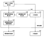
- FIG. 2 is a functional block diagram illustrating an example of a functional configuration of functions related to the focusing process of the control device 140 according to the first embodiment.
- functions related to the focusing process among the functions of the control device 140 are conceptually illustrated as blocks.
- FIG. 2 for the sake of explanation, as a functional block other than the control device 140, a front lens insertion / extraction detection unit 151, a microscope unit moving unit 152, and an AF driving unit 153 are illustrated together. First, these functions will be described.
- the front lens insertion / extraction detection unit 151 has a function of detecting insertion / extraction of the front lens 131 on the optical axis by the front lens insertion / extraction unit 130.
- the microscope apparatus 10 is equipped with a detection device for detecting insertion / removal of the front lens 131 on the optical axis, and the front lens insertion / extraction detection unit 151 includes: It is comprised by such a detection apparatus.
- the detection device constituting the front lens insertion / extraction detection unit 151 may be any device as long as it can detect the insertion / extraction of the front lens 131 on the optical axis, and its specific type is not limited.
- an encoder that detects the rotation angle may be provided on the rotary shaft 133 of the front lens insertion / extraction unit 130, and the encoder may function as the front lens insertion / extraction detection unit 151.
- the detected value of the rotation angle of the rotary shaft 133 by the encoder represents the rotation angle of the front lens holding member 132, and can indicate the position of the front lens 131. Therefore, the rotation angle is detected. By doing so, the insertion / extraction of the front lens 131 on the optical axis can also be detected.
- a sensor for detecting an object existing on the optical axis of the microscope unit 110 may be provided, and the sensor may function as the front lens insertion / extraction detection unit 151.
- the pre-lens insertion / extraction detection unit 151 includes information indicating that the detected pre-lens 131 has been inserted on the optical axis or information indicating that the pre-lens 131 has been removed from the optical axis. To the microscope unit movement amount calculation unit 141 and the AF control unit 143.
- the microscope unit moving unit 152 has a function of moving the microscope unit 110 in the optical axis direction under the control of the microscope unit moving unit drive control unit 142 of the control device 140 described later.
- the microscope unit moving unit 152 includes the linear motion mechanism 122 shown in FIG.
- the AF driving unit 153 has a function of executing an operation related to the AF function in the microscope unit 110 under the control of the AF control unit 143 of the control device 140 described later.
- the AF driving unit 153 is configured by a driving mechanism that is provided in the microscope unit 110 and that moves the focus lens of the optical system 113 on the optical axis, which has been described with reference to FIG.
- the control device 140 includes, as its function, a microscope unit movement amount calculation unit 141, a microscope unit movement unit drive control unit 142, an AF control unit 143, and a microscope unit position calculation unit 144. . These functions are realized when the processor of the control device 140 executes arithmetic processing according to a predetermined program.
- the microscope unit movement amount calculation unit 141 uses the information indicating that the front lens 131 is inserted on the optical axis as a trigger from the front lens insertion / extraction detection unit 151, and triggers the front lens 131 before the design.
- the amount of movement of the microscope unit 110 in the optical axis direction from the current position (that is, the position when the front lens 131 is inserted on the optical axis) such as the position of the mounting lens position is calculated.
- the microscope apparatus 10 since the distance between the microscope unit 110 and the front lens 131 in the optical axis direction is fixed, the front lens can be obtained by moving the microscope unit 110 in the optical axis direction. 131 can also be moved in the optical axis direction.
- the microscope unit movement amount calculation unit 141 receives information from the microscope unit position calculation unit 144 regarding the position of the microscope unit 110 in the optical axis direction with respect to the eye 401 when the front lens 131 is inserted.
- information about the position of the microscope unit 110 in the optical axis direction with respect to the eye to be examined 401 when the front lens 131 is inserted is simply abbreviated as “position information of the microscope unit 110”.
- position information of the microscope unit 110 Provided.
- the distance from the eye 401 to be examined at the designed pre-lens position and the distance in the vertical direction between the microscope unit 110 and the pre-lens 131 are determined in advance. Information about these values is input to the device 140 in advance.
- the microscope unit movement amount calculation unit 141 is configured to move the head lens 131 to the design head lens position based on the information about these values and the position information of the microscope unit 110, in the optical axis direction of the microscope unit 110. The amount of movement at can be calculated.
- the microscope unit movement amount calculation unit 141 provides the information about the calculated movement amount of the microscope unit 110 in the optical axis direction to the microscope unit movement unit drive control unit 142.
- the microscope unit movement unit drive control unit 142 moves the microscope unit 110 by the movement amount. Then, the microscope unit moving unit 152 is operated (specifically, the actuator of the linear motion mechanism 122 of the holding unit 120 is operated). Accordingly, the front lens 131 is moved in the optical axis direction to the design front lens position.
- the AF control unit 143 performs control related to the AF function in the microscope unit 110.
- the AF control unit calculates the amount of movement of the focus lens of the optical system 113 so that a predetermined position is focused according to a predetermined method related to AF. Then, the operation of the AF driving unit 153 is controlled to move the focus lens by the calculated movement amount, thereby executing the AF operation.
- the AF method is not limited, and either an active method or a passive method may be used. When the passive method is used, various known methods such as a phase difference detection method and a contrast method may be applied.
- the AF control unit 143 When observing the anterior segment of the eye 401 to be examined, the AF control unit 143 causes the microscope unit 110 to perform an AF operation so that the anterior segment is in focus. At this time, the AF control unit 143 provides the microscope position calculation unit 144 with information on the focal length of the microscope unit 110 when observing the anterior segment of the eye 401 to be examined.
- the AF control unit 143 forms a fundus image by the front lens 131.
- the microscope unit 110 is caused to perform an AF operation so that the position is in focus.
- the AF control unit 143 waits for the front lens 131 to be moved to the design pre-lens position by the microscope unit moving unit drive control unit 142, and then executes the AF operation.
- the front lens 131 is moved to the design front lens position by the microscope unit moving unit drive control unit 142.
- the imaging position of the fundus image by the front lens 131 should match the design fundus image position 403, ideally, in the microscope unit 110, the focus is on the design fundus image position 403. If the focus is adjusted so that it fits, a clear fundus image should be obtained, and there is no need to perform the AF operation.
- the fundus of the front lens 131 after the movement due to factors such as an alignment error when the front lens 131 moves and individual differences in characteristics (size, optical characteristics, etc.) of the eye 401 to be examined.
- the image formation position of the image may slightly shift from the designed fundus image position 403. Therefore, as described above, it is necessary to execute the AF operation by the AF control unit 143 so that the focal position of the true fundus image is focused.
- the AF control unit 143 performs the AF operation over the entire adjustable range of the focal length.
- the AF operation may be executed with the vicinity of the designed fundus image position 403 as a focusing target. Thereby, focusing can be performed efficiently, and the focusing process can be executed in a shorter time.
- the AF control unit 143 is provided with position information of the microscope unit 110 from the microscope unit position calculation unit 144.
- the distance from the design eye fundus image position 403 from the eye 401 to be examined is determined in advance. In the first embodiment, information about the value is input to the control device 140 in advance. .
- the AF control unit 143 focuses on the vicinity of the designed fundus image position 403 based on the information about the distance value of the designed fundus image position 403 from the eye 401 to be examined and the position information of the microscope unit 110. The action can be executed.
- the microscope position calculation unit 144 inserts the front lens 131 based on information about the focal length of the microscope unit 110 when the anterior eye part of the eye 401 to be examined is provided from the AF control unit 143.
- the position in the optical axis direction of the microscope unit 110 with respect to the eye to be examined 401 at the time point is calculated. Specifically, since the structure of the microscope unit 110 is known, if the focal length of the microscope unit 110 is known when observing the anterior segment of the eye 401 to be examined, the WD of the microscope unit 110 with respect to the anterior segment is known. That is, the position of the microscope unit 110 in the optical axis direction with respect to the eye 401 to be examined can be calculated.
- Parameters for the structure of the microscope unit 110 are input in advance to the control device 140, and the microscope unit position calculation unit 144 is configured to observe the parameters and the anterior segment of the eye 401 to be examined. Based on the information about the focal length 110, the position of the microscope unit 110 in the optical axis direction with respect to the eye 401 when the front lens 131 is inserted can be calculated.
- the microscope unit position calculation unit 144 obtains information about the position of the microscope unit 110 in the optical axis direction with respect to the subject eye 401 at the time when the calculated front lens 131 is inserted, and the microscope unit movement amount calculation unit 141 and the AF control unit. 143.
- the focal length adjustment function in the control device 140 has been described above. As described above, according to the first embodiment, when the front lens 131 is inserted on the optical axis, the focusing process for clearly observing the fundus image is automatically performed by the control device 140. Executed. Therefore, since it is not necessary to perform the focusing process manually, the medical staff is freed from complicated work and the efficiency of the operation can be further improved.
- the control device 140 may automatically perform a focusing process for clearly obtaining an image of the anterior segment. In this case, the control device 140 returns the position of the front lens 131 in the optical axis direction and the focal length of the microscope unit 110 to the state before the front lens 131 is inserted on the optical axis.
- the microscope unit moving unit 152 and the AF driving unit 153 may be operated by the microscope unit moving unit driving control unit 142 and the AF control unit 143, respectively.
- the focusing process is automatically performed when the front lens 131 is inserted on the optical axis.
- the first embodiment is not limited to this example.
- another process for clearly obtaining a fundus image may be further automatically performed.
- the microscope unit 110 has an AE function
- the control device 140 causes the fundus imaged by the front lens 131 by the AE function.
- the exposure of the microscope unit 110 may be adjusted according to the brightness of the image.
- the observation image becomes an inverted image in which the top, bottom, left and right are reversed.
- the control device 140 may automatically perform a process of converting the reverse image into a normal image.
- the conversion process may be performed together with the image processing performed on the image signal acquired by the microscope unit 110. Note that these exposure adjustments and image conversions may also be automatically performed when the front lens 131 is removed from the optical axis.
- the holding unit 120 is configured by the stand 121 and the linear motion mechanism 122.
- the first embodiment is not limited to such an example.
- maintenance part 120 should just be able to move the microscope part 110 to an optical axis direction
- the structure may be arbitrary.
- the holding unit 120 may be configured as a multi-link structure in which a plurality of links are sequentially connected via a plurality of rotating shaft portions. If the multi-link structure is configured to have at least 6 degrees of freedom with respect to the movement of the front-end microscope unit 110, the microscope unit 110 can be held at an arbitrary position and posture within the movable range of the multi-link structure. Therefore, the configuration of the holding unit 120 shown in the figure can be substituted.
- the microscope unit position calculation unit 144 calculates the position of the microscope unit 110 in the optical axis direction with respect to the subject eye 401 when the front lens 131 is inserted.
- the said position of the microscope part 110 was calculated based on the information about the focal distance of the microscope part 110 in observing an eye part
- 1st Embodiment is not limited to this example.
- the method by which the microscope unit position calculation unit 144 calculates the position of the microscope unit 110 is not limited, and any method may be applied as this method.
- the microscope apparatus 10 may be provided with a distance sensor that detects the distance of the object on the optical axis from the microscope unit 110. In this case, the microscope unit position calculation unit 144 can calculate the position of the microscope unit 110 based on the detection value by the distance sensor.
- the microscope unit 110 is an electronic imaging type microscope unit, but the first embodiment is not limited to such an example.
- the microscope unit 110 may be an optical microscope unit that magnifies and observes the surgical unit through the optical system when the operator directly looks into the microscope unit from the eyepiece unit.
- the AF function method mounted on the microscope unit 110 is limited to the active method, it is possible to execute an automatic focusing process similar to the case of the electronic imaging type microscope unit. is there.
- the electronic imaging microscope device 10 can enjoy the following advantages as compared with a microscope device (hereinafter also referred to as an optical microscope device) including an optical microscope unit.
- a microscope device hereinafter also referred to as an optical microscope device
- the electronic imaging type microscope apparatus 10 since the adjustable range of the focal length is large, the WD changeable range of the microscope unit 110 can also be increased, and the microscope unit 110 having a high degree of freedom during observation can be arranged. It becomes possible.
- functions such as an AE function and an electronic zoom function can be mounted, so that the convenience for the operator can be further improved.
- the microscope unit 110 can be configured more compactly, the entire microscope apparatus 10 can be reduced in size. In view of these advantages, it can be said that the electronic imaging microscope apparatus 10 is preferably used.
- the AF function in the microscope unit 110 is used.
- an electronic imaging microscope unit such as the microscope unit 110 includes an optical microscope unit. Compared to, many have an AF function. Therefore, by using the electronic imaging microscope unit 110, it is possible to execute the focusing process according to the first embodiment without providing an additional configuration and function for AF. Also in this respect, in the first embodiment, it can be said that it is preferable to use the electronic imaging microscope unit 110 rather than the optical microscope unit.
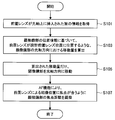
- FIG. 3 is a flowchart illustrating an example of a processing procedure of a control method of the microscope apparatus 10 relating to the focusing process according to the first embodiment.
- each process shown in FIG. 3 corresponds to each process executed by the control device 140 shown in FIG. 2, and the processor constituting the control device 140 executes arithmetic processing according to a predetermined program.
- Each process shown in 3 may be executed.
- the details of each process shown in FIG. 3 have already been described when the function of the control device 140 is described. Therefore, in the description of the process procedure of the following control method, only the outline of each process is described. Detailed description is omitted.
- step S101 information indicating that the front lens 131 has been inserted on the optical axis is acquired.
- the process in step S101 is a process in which information indicating that the front lens 131 has been inserted on the optical axis is input from the front lens insertion / extraction detection unit 151 to the control device 140 described with reference to FIG. It corresponds to.
- step S103 based on the positional information of the microscope unit 110, the amount of movement of the microscope unit 110 in the optical axis direction such that the front lens 131 is positioned at the design front lens position is calculated (step S103).
- the processing in step S103 corresponds to the processing executed by the microscope unit movement amount calculation unit 141 shown in FIG.
- step S105 the microscope unit 110 is moved in the optical axis direction by the calculated movement amount.
- the processing in step S105 corresponds to the processing executed by the microscope unit moving unit drive control unit 142 shown in FIG.
- step S107 the focal length of the microscope unit 110 is adjusted by the AF function so that the image forming position by the front lens 131 is in focus.
- the process in step S107 corresponds to the process executed by the AF control unit 143 shown in FIG.
- the distance between the microscope unit 110 and the front lens 131 in the optical axis direction is fixed to a constant value.
- the first embodiment is not limited to such an example.
- the microscope apparatus 10 may be configured such that the distance between the microscope unit 110 and the front lens 131 in the optical axis direction is variable.
- the distance between the microscope unit 110 and the front lens 131 in the optical axis direction is constant as in the configuration example described above, the distance between the front lens 131 and the eye 401 to be examined is adjusted to a predetermined value.
- the WD of the microscope unit 110 during fundus observation is constant.
- the distance between the microscope unit 110 and the front lens 131 in the optical axis direction is variable, even if the distance between the front lens 131 and the eye 401 to be examined is adjusted to a predetermined value.
- the WD of the microscope unit 110 can be changed by appropriately adjusting the distance in the optical axis direction between the microscope unit 110 and the front lens 131.
- such a microscope apparatus in which the distance between the microscope unit 110 and the front lens 131 in the optical axis direction is variable and a control method of the microscope apparatus will be described. .
- the electronic imaging microscope unit 110 has a feature that the WD can be changed relatively freely. Therefore, in ophthalmic surgery using the microscope apparatus 10, there may be a demand for performing an operation while freely changing the WD of the microscope unit 110 by utilizing this feature depending on the situation of the operation.
- the WD of the microscope unit 110 can be freely changed during observation of the anterior segment, but the WD becomes constant during observation of the fundus.
- the WD of the microscope unit 110 can be freely changed even during fundus observation, so that it is possible to meet the above demand and further improve the convenience of the surgeon. .
- a smooth operation is realized as in the above-described configuration example, and an effect of further improving the convenience for the operator can be obtained.
- the front lens insertion / extraction unit has substantially the same configuration as the front lens insertion / extraction unit 130 shown in FIG. 1, but the position of the front lens 131 relative to the microscope unit 110 in the optical axis direction. Is configured to be changeable.
- the front lens insertion / extraction unit has a configuration in which the front lens 131 is held at the front end of the front lens holding member, similarly to the front lens insertion / extraction unit 130 shown in FIG. .
- the front lens holding member has substantially the same configuration as that of the front lens holding member 132 shown in FIG. 1, but a plurality of links are connected to each other by a rotary shaft portion so as to be rotatable.
- the rotary shaft portion is provided with an actuator.
- the actuator When the actuator is driven by control from the control device 240 described later, the angle between the links constituting the front lens holding member is changed, and the microscope portion 110 is changed.
- the position of the front lens 131 in the optical axis direction that is, the distance between the microscope unit 110 and the front lens 131 can be changed.
- a control device 240 is provided instead of the control device 140 shown in FIG.
- the configuration and function of the control device 240 are the same as those of the control device 140 except for the focusing process when the front lens 131 is inserted and removed.
- the function regarding the focusing process in the control apparatus 240 which concerns on this modification which is a difference with the control apparatus 140 is demonstrated in detail.
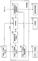
- FIG. 4 is a functional block diagram illustrating an example of a functional configuration of functions related to the focusing process of the control device 240 according to a modification of the first embodiment.
- functions related to the focusing process are conceptually illustrated as blocks.
- a front lens insertion / extraction detection unit 151, a microscope unit moving unit 152, an AF driving unit 153, and a front lens moving unit 154 are also illustrated as functional blocks other than the control device 240. ing. Among these, the functions of the front lens insertion / extraction detection unit 151, the microscope unit moving unit 152, and the AF driving unit 153 are the same as those shown in FIG. However, in the present modification, the front lens insertion / extraction detection unit 151 has information that the detected front lens 131 has been inserted on the optical axis or information that the front lens 131 has been removed from the optical axis. Is provided to the front lens movement amount calculation unit 241 and the AF control unit 143 of the control device 240 described later.
- the front lens moving unit 154 has a function of moving the front lens 131 in the optical axis direction under the control of the front lens moving unit drive control unit 242 of the control device 240 described later.
- the pre-lens moving unit 154 is configured by a rotating shaft that forms the pre-lens holding member described above.
- control device 240 functions as a front lens movement amount calculation unit 241, a front lens movement unit drive control unit 242, a microscope unit movement unit drive control unit 142, and an AF control unit 143. And a microscope unit position calculation unit 144. These functions are realized by the processor of the control device 240 executing arithmetic processing according to a predetermined program.
- the pre-lens movement amount calculation unit 241 is designed by using the pre-lens 131 as a trigger when information indicating that the pre-lens 131 has been inserted on the optical axis is transmitted from the pre-lens insertion / extraction detection unit 151.
- the amount of movement of the front lens 131 in the optical axis direction from the current position that is, the position when the front lens 131 is inserted on the optical axis
- the position of the front lens is calculated.
- the position information of the microscope unit 110 is provided from the microscope unit position calculation unit 144 to the front lens movement amount calculation unit 241.
- the initial position of the front lens 131 in the optical axis direction with respect to the microscope unit 110 at the time when the front lens 131 is inserted on the optical axis is a predetermined position. Configured to be.
- the values of the distance of the designed pre-lens position from the eye 401 to be examined and the initial position of the pre-lens 131 in the optical axis direction are determined in advance, and in this modification, the controller 240 is preliminarily determined. Information about these values is entered.
- the pre-lens movement amount calculation unit 241 moves the pre-lens 131 to the design pre-lens position based on the information about these values and the position information of the microscope unit 110. The amount of movement in the optical axis direction is calculated.
- the pre-lens movement amount calculation unit 241 provides information about the calculated movement amount of the front lens 131 in the optical axis direction to the pre-lens movement unit drive control unit 242.
- the front lens movement unit drive control unit 242 moves the front lens 131 by the movement amount.
- the pre-lens moving unit 154 is operated so as to move (specifically, an actuator provided on a rotary shaft portion constituting a front lens holding member of the pre-lens insertion / extraction unit is operated). Accordingly, the front lens 131 is moved in the optical axis direction to the design front lens position.
- the microscope unit 110 is movable in the optical axis direction in accordance with an instruction input by the operator during fundus observation.
- the front lens moving unit drive control unit 242 is provided with information on the amount of movement of the microscope unit 110 from the microscope unit moving unit drive control unit 142, and the front lens moving unit drive control unit 242. 242 is based on the information and the position information of the microscope unit 110 provided from the microscope unit position calculation unit 144, even if the microscope unit 110 is moved, the head lens 131 is positioned at the design head lens position. Then, the front lens moving unit 154 is operated so as to continue.
- the function of the AF control unit 143 is substantially the same as the function in FIG. That is, when observing the anterior segment of the eye 401 to be examined, the AF control unit 143 causes the microscope unit 110 to perform an AF operation so that the anterior segment is in focus. At this time, the AF control unit 143 provides the microscope position calculation unit 144 with information about the focal length of the microscope unit 110 when observing the anterior segment of the eye 401 to be examined.
- the AF control unit 143 forms a fundus image by the front lens 131.
- the microscope unit 110 is caused to perform an AF operation so that the position is in focus.
- the AF control unit 143 waits for the front lens moving unit drive control unit 242 to move the front lens 131 to the design front lens position, and then executes the AF operation.
- the focal point is set so that the designed fundus image position 403 is in focus. If the alignment is performed, a clear fundus image should be obtained, and it is not necessary to perform the AF operation.
- the image formation position of the fundus image by the moved front lens 131 is slightly shifted from the design fundus image position 403 due to various factors. Therefore, as described above, it is necessary to execute the AF operation by the AF control unit 143 so that the focal position of the true fundus image is focused.
- the AF control unit 143 is provided with position information of the microscope unit 110 from the microscope unit position calculation unit 144. Therefore, the AF control unit 143 determines the information from the microscope unit 110 to the designed fundus image position 403 based on the information and the information about the distance from the eye 401 to be examined which is the pre-designed lens position input to the control device 240 in advance. The distance can be grasped, and the AF operation can be executed with the vicinity of the design fundus image position 403 as a focusing target. Thereby, focusing can be performed efficiently, and the focusing process can be executed in a shorter time.
- the microscope unit 110 can move in the optical axis direction in accordance with an instruction input by the operator during fundus observation.
- the AF control unit 143 continues to cause the AF driving unit 153 to perform an AF operation for focusing on the imaging position of the fundus image by the front lens 131.
- the AF control unit 143 is provided with information about the amount of movement of the microscope unit 110 from the microscope unit moving unit drive control unit 142, and the AF control unit 143 receives the information.
- the AF operation is designed by calculating the distance in the vertical direction between the microscope unit 110 and the design fundus image position 403 as needed based on the position information of the microscope unit 110 provided from the microscope unit position calculation unit 144.
- the vicinity of the fundus image position 403 can be continuously executed as a focus target.
- the function of the microscope unit moving unit drive control unit 142 is substantially the same as the function in FIG.
- the microscope unit moving unit drive control unit 142 does not automatically move the microscope unit 110 during fundus observation, but operates the microscope unit moving unit 152 according to an instruction input by the operator ( Specifically, the actuator of the linear motion mechanism 122 of the holding unit 120 is operated), and the microscope unit 110 is moved in the optical axis direction by an amount according to the instruction input.
- the microscope unit 110 can be freely positioned on the optical axis within the WD range by an instruction input by the operator not only when observing the anterior segment but also when observing the fundus.
- the microscope unit moving unit drive control unit 142 displays information about the amount of movement of the microscope unit 110 as information about the front lens moving unit drive control unit 242 and the AF. Provided to the control unit 143.
- the function of the microscope unit position calculation unit 144 is substantially the same as the function in FIG. 2 described above.
- the microscope unit position calculation unit 144 is based on the information about the focal length of the microscope unit 110 when observing the anterior segment of the eye 401 provided from the AF control unit 143.
- the position in the optical axis direction of the microscope unit 110 with respect to the eye to be examined 401 at the time when is inserted is calculated.
- the microscope unit position calculation unit 144 obtains information about the position in the optical axis direction of the microscope unit 110 with respect to the subject eye 401 at the time when the calculated front lens 131 is inserted, and the front lens movement amount calculation unit 241 and AF control. Part 143.
- the function related to the focusing process of the control device 240 has been described above.
- the focusing process when the front lens 131 is inserted on the optical axis is automatically performed as in the configuration example described above. Therefore, a smoother operation can be realized.
- the microscope unit at the time of observing the anterior eye unit Depending on the position of 110 in the optical axis direction, the front lens 131 may not be able to be moved to the design front lens position at the position of the microscope unit 110.
- the pre-lens moving unit drive control unit 242 moves the pre-lens 131 to the designed pre-lens position via the microscope unit moving unit drive control unit 142 to move the microscope unit moving unit 152.
- the microscope unit 110 By operating the microscope unit 110, the microscope unit 110 is appropriately moved in the optical axis direction to a predetermined position where the movable position of the front lens 131 in the optical axis direction relative to the microscope unit 110 is included in the movable range. Also good.
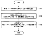
- FIG. 5 is a flowchart illustrating an example of a processing procedure of the control method of the microscope apparatus related to the focusing process according to a modification of the first embodiment.
- Each process shown in FIG. 5 corresponds to each process executed by the control device 240 shown in FIG. 4, and the processor constituting the control device 240 executes arithmetic processing according to a predetermined program.
- Each process shown in FIG. Since the details of each process shown in FIG. 5 have already been described when the function of the control device 240 is described, the following description of the processing procedure of the control method will only give an overview of each process. Detailed description is omitted.
- Step S201 information indicating that the front lens 131 has been inserted on the optical axis is acquired.
- the process in step S201 is the same as the process in step S101 shown in FIG.
- step S203 based on the positional information of the microscope unit 110, the amount of movement of the front lens 131 in the optical axis direction so that the front lens 131 is positioned at the design front lens position is calculated (step S203).
- the processing in step S203 corresponds to the processing executed by the front lens movement amount calculation unit 241 shown in FIG.
- step S205 the front lens 131 is moved in the optical axis direction by the calculated movement amount.
- the processing in step S205 corresponds to the processing executed by the front lens moving unit drive control unit 242 shown in FIG.
- step S207 when there is an instruction input from the surgeon, the microscope unit 110 is moved in the optical axis direction according to the instruction input (step S207).
- the processing in step S207 corresponds to the processing executed by the microscope unit moving unit drive control unit 142 shown in FIG. If there is no instruction input from the operator, step S207 is skipped.
- the focal length of the microscope unit 110 is adjusted by the AF function so that the image forming position by the front lens 131 is in focus (step S209).
- the microscope unit 110 is moving in accordance with an instruction input from the surgeon in step S207, the focal length of the microscope unit 110 can be adjusted based on information about the amount of movement of the microscope unit 110.
- the process in step S209 corresponds to the process executed by the AF control unit 143 shown in FIG.
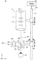
- FIG. 6 is a diagram illustrating a schematic configuration of a microscope apparatus according to the second embodiment.
- a microscope apparatus 30 includes a microscope unit 110 for magnifying and observing an eye 401 to be examined, an arm unit 120 (holding unit 120) that holds the microscope unit 110, and a microscope unit.
- a pre-lens insertion / extraction unit 330 that inserts / extracts the pre-lens on the optical axis 110, and a controller 340 that integrally controls the operation of the microscope apparatus 30.
- the microscope unit 110 is arranged directly above the eye 401 so that the optical axis thereof is substantially parallel to the vertical direction. The device 30 will be described.
- the configurations and functions of the microscope unit 110 and the holding unit 120 are the same as the configurations and functions of these members in the first embodiment, detailed descriptions thereof are omitted here. However, as will be described later, in the second embodiment, since the light source 332 of illumination light is provided in the front lens insertion / extraction unit 330, the light source is not provided in the microscope unit 110.
- the front lens insertion / removal unit 330 includes a front lens 331, an illumination light source 332, an illumination optical system 333, a half mirror 334, the front lens 331, a light source 332, an illumination optical system 333, and a half mirror 334. Is disposed between the base end of the front lens holding member 338 and the stand 121 of the holding unit 120, and the front lens holding member 338 is connected to the front lens. And a rotation shaft portion 339 that supports the stand 121 so as to be rotatable about the vertical direction as a rotation axis with the base end of the holding member 338 as a base point.
- the front lens insertion / removal unit 330 is attached to the stand 121 and configured separately from the microscope unit 110.
- the front lens 331 has the same configuration and function as the front lens 131 in the first embodiment.
- the light source 332 is, for example, an LED (Light Emitting Diode) or an LD (Laser Diode), and emits light having a predetermined intensity and a predetermined wavelength under the control of the control device 340.
- LED Light Emitting Diode
- LD Laser Diode
- the illumination optical system 333 has a function of guiding the emitted light from the light source 332 to the outside and adjusting the characteristics of the emitted light to desired characteristics suitable for fundus observation.
- one lens is shown as the illumination optical system 333 for convenience, but the illumination optical system 333 is configured by a plurality of lenses or a combination of lenses and various other optical elements. May be.
- the half mirror 334 directs the traveling direction of the emitted light from the light source 332 that has passed through the illumination optical system 333 downward, and the emitted light in a state where the front lens 331 is inserted on the optical axis of the microscope unit 110. Is made to coincide with the optical axis of the microscope unit 110.
- the front lens holding member 338 is mainly composed of three members (a first member 335, a second member 336, and a third member 337).
- the first member 335 and the second member 336 have hollow cylindrical shapes having different sizes.
- the first member 335 having a large diameter is disposed so that its central axis is substantially parallel to the vertical direction. Both ends of the first member 335 are opened, and the front lens 331 is fitted into the lower opening.
- the second member 336 having a small diameter is disposed so that the central axis thereof is substantially parallel to the horizontal direction, and the first member has one end abutting against the side wall of the first member 335.
- a second member 336 is positioned with respect to 335.
- An opening is provided at a contact portion of the side wall of the first member 335 with the second member 336, and the inside of the first member 335 and the second member 336 is interposed through the opening. Communicate. The other end of the second member 336 is bottomed. As described above, the first member 335 and the second member 336 are combined to form one housing.
- the casing has a cylinder with a smaller diameter (that is, the second member 336) with respect to the side surface of the cylinder with a larger diameter (that is, the first member 335), and the central axis thereof is substantially the same as the side surface. It has the shape connected so that it may become perpendicular
- the light source 332 is disposed at the bottomed portion of one end of the second member 336 in the casing, and the illumination optical system 333 is disposed at the rear stage of the light source 332 inside the second member 336.
- a half mirror 334 is disposed at a position corresponding to the intersection of the central axis of the first member 335 and the central axis of the second member 336.
- the half mirror 334 has the front lens 131 inserted on the optical axis of the microscope unit 110 so that the traveling direction of the emitted light from the light source 332 that has passed through the illumination optical system 333 is directed downward.
- FIG. 6 With this configuration, in a state where the front lens 131 is inserted, the emitted light (that is, illumination light) from the light source 332 directed downward by the half mirror 334 passes through the front lens 331 and is covered. The light enters the optometry 401.
- the optical path of the illumination light is schematically indicated by an arrow. Reflected light (that is, observation light) of the illumination light from the eye 401 to be inspected passes through the front lens 331 and the half mirror 334, is directed upward, and is incident on the microscope unit 110.
- the third member 337 of the front lens holding member 338 is a long member, one end of which is fixed to the side of the first member 335 opposite to the side where the second member 336 exists. Connected to. The other end of the third member 337 is rotatably held by the rotating shaft portion 339 with respect to the stand 121 with the vertical direction as the rotating shaft direction.
- the side connected to the stand 121 that is, the side on which the third member 337 is located
- the opposite side that is, the first side
- the side on which the second member 336 is located is also referred to as the tip side.
- the third member 337 is rotated with respect to the stand 121 via the rotation shaft portion 339 with the vertical direction as the rotation axis direction, so that the housing made up of the first member 335 and the second member 336 and the inside thereof Both of these members (that is, the entire front lens insertion / removal unit 330) rotate with the vertical direction as the rotation axis direction.
- the insertion and removal of the front lens 331 on the optical axis of the microscope unit 110 is realized (FIG. 6 illustrates the state where the front lens 331 is inserted on the optical axis).
- the rotation shaft portion 339 is provided with an actuator.
- the rotation shaft portion 339 operates to rotate the front lens insertion / removal unit 330, that is, the front.
- the mounting lens 331 is inserted into and removed from the optical axis.
- the position of the rotating shaft portion 339 in the vertical direction (that is, the position of the front lens insertion / extraction unit 330 in the vertical direction) can be moved manually or electrically via an actuator or the like.
- the height of the eye 401 to be examined from the upper surface of the operating table when the patient lies on the operating table the size of the eye 401 to be examined, etc.
- the mounting lens 331 is inserted on the optical axis, the image formation position of the fundus image by the front lens 331 coincides with the design fundus image position 403 (that is, the front lens 331 is positioned at the design front lens position).
- the position of the front lens insertion / removal unit 330 in the vertical direction can be adjusted.
- the movement of the front lens insertion / removal unit 330 in the vertical direction is performed electrically, the movement may also be executed by control from the control device 340.
- the control device 340 includes, for example, a processor such as a CPU or DSP, or a control board on which these processors and storage elements such as a memory are mounted. Each function in the control device 340 is realized by a processor constituting the control device 340 executing arithmetic processing according to a predetermined program.
- a processor constituting the control device 340 executing arithmetic processing according to a predetermined program.
- FIG. 6 for the sake of convenience, an arrow indicating the connection between the control device 340 and the stand 121 of the holding unit 120 is shown in FIG. 6.
- the control device 340 and each member of the microscope device 30 are connected so as to be able to exchange various types of information using various known wired or wireless communication methods.
- control device 340 control of the operation of the microscope unit 110 (for example, adjustment of magnification, focal length, etc.), display control of an image photographed by the microscope unit 110, operation of the holding unit 120 (for example, the linear motion mechanism 122).
- the control of (operation) is the same as those functions of the control device 140 in the first embodiment.
- the control device 340 has a function of controlling the operation of the front lens insertion / extraction unit 330. Specifically, the control device 340 operates the rotation shaft portion 339 and rotates the front lens holding member 338 of the front lens insertion / extraction unit 330 with respect to the microscope unit 110, thereby causing the light of the front lens 331. Execute insertion / removal on the axis.
- the control device 340 controls the microscope unit 110, the holding unit 120, the front lens insertion / extraction unit 330, and the display device (not shown) that displays a captured image by the microscope unit 110, for example, according to an instruction input by an operator. Is called.
- the microscope apparatus 30 is provided with an input device such as a foot switch and a touch panel (not shown), and the controller 340 performs the above-described configuration by inputting various instructions via the input device. Operate according to the instruction input.
- the front lens 331 in order to obtain a clear fundus image, according to the insertion of the front lens 331 on the optical axis by the front lens insertion / extraction unit 330. It is necessary to perform the focusing process of the microscope unit 110. In the second embodiment, when the front lens 331 is inserted on the optical axis, this focusing process is automatically performed under the control of the control device 340.
- FIG. 7 is a functional block diagram illustrating an example of a functional configuration of functions related to the focusing process of the control device 340 according to the second embodiment.
- functions related to the focusing process among the functions of the control device 340 are conceptually illustrated as blocks.
- a front lens insertion / extraction detection unit 151 As a functional block other than the control device 340, a front lens insertion / extraction detection unit 151, a microscope unit moving unit 152, and an AF driving unit 153 are illustrated together. Since these functions are the same as those in the first embodiment shown in FIG. 2, the description thereof is omitted here.
- the pre-lens insertion / extraction detection unit 151 indicates that the detected pre-lens 331 has been inserted on the optical axis or that the pre-lens 331 has been removed from the optical axis. Is provided to the AF control unit 143 of the control device 340 described later.
- the control device 340 includes a microscope unit moving unit drive control unit 142, an AF control unit 143, and a microscope unit position calculating unit 144 as its functions. These functions are realized by the processor of the control device 340 executing arithmetic processing according to a predetermined program.
- the function of the AF control unit 143 is substantially the same as the function in the first embodiment shown in FIG. That is, when observing the anterior segment of the eye 401 to be examined, the AF control unit 143 causes the microscope unit 110 to perform an AF operation so that the anterior segment is in focus. At this time, the AF control unit 143 provides the microscope position calculation unit 144 with information about the focal length of the microscope unit 110 when observing the anterior segment of the eye 401 to be examined.
- the AF control unit 143 forms a fundus image by the front lens 331.
- the microscope unit 110 is caused to perform an AF operation so that the position is in focus.
- a process of moving the pre-lens 131 to the design pre-lens position in the optical axis direction is executed.
- the AF control unit 143 has to wait without performing the AF operation until the processing is completed.
- the front lens 331 is optically moved by the front lens insertion / removal unit 330.
- the pre-lens 331 is already positioned at the design pre-lens position. Therefore, unlike the first embodiment, there is no need to perform processing for moving the front lens 331 in the optical axis direction, and immediately after the front lens 331 is inserted on the optical axis, the AF control unit 143 is immediately inserted. The control of the AF operation by can be executed. Therefore, the focusing process related to the insertion of the front lens 331 on the optical axis can be performed more smoothly in a shorter time than in the first embodiment.
- the front lens 331 is located at the design front lens position when the front lens 331 is inserted on the optical axis as described above, ideally, in the microscope unit 110, If focusing is performed so that the design fundus image position 403 is focused, a clear fundus image should be obtained, and it is not necessary to perform AF operation. However, in actuality, for example, due to factors such as changes in the posture of the patient, the image formation position of the fundus image by the front lens 331 after insertion on the optical axis may be slightly shifted from the design fundus image position 403. is there. Therefore, as described above, it is necessary to execute the AF operation by the AF control unit 143 so that the focal position of the true fundus image is focused.
- the AF control unit 143 is provided with position information of the microscope unit 110 from the microscope unit position calculation unit 144. Therefore, the AF control unit 143 inserts the front lens 331 on the optical axis based on the information and the information about the distance from the eye 401 to be examined at the design front lens position input in advance to the control device 340. The distance from the microscope unit 110 to the design fundus image position 403 at the time can be grasped. Using this information, the AF control unit 143 can execute an AF operation with the vicinity of the designed fundus image position 403 as a focusing target, as in the first embodiment. Thereby, focusing can be performed efficiently, and the focusing process can be executed in a shorter time.
- the microscope unit 110 is movable in accordance with an instruction input by the operator during fundus observation.
- the AF control unit 143 focuses the AF drive unit 153 on the fundus image forming position by the front lens 331, as in the modification of the first embodiment.
- the AF operation for matching is continued to be executed. Thereby, even when the microscope unit 110 is moved, a clear fundus image is always taken by the microscope unit 110.
- the AF control unit 143 is provided with information about the amount of movement of the microscope unit 110 from the microscope unit moving unit drive control unit 142, and the AF control unit 143 receives the information.
- the AF operation is designed by calculating the distance in the vertical direction between the microscope unit 110 and the design fundus image position 403 as needed based on the position information of the microscope unit 110 provided from the microscope unit position calculation unit 144.
- the vicinity of the fundus image position 403 can be continuously executed as a focus target.
- the function of the microscope unit moving unit drive control unit 142 is substantially the same as the function in the first embodiment described above. However, in the second embodiment, as in the modification of the first embodiment, the microscope unit moving unit drive control unit 142 does not automatically move the microscope unit 110 at the time of fundus observation.
- the microscope unit moving unit 152 is operated according to an instruction input by the person (specifically, the actuator of the linear motion mechanism 122 of the holding unit 120 is operated), and the microscope unit 110 is moved by an amount according to the instruction input.
- the microscope unit 110 can be freely moved on the optical axis within the range of the WD by an instruction input by the operator not only when observing the anterior segment but also when observing the fundus. It is possible to arrange at various positions.
- the microscope unit moving unit drive control unit 142 provides the AF control unit 143 with information on the amount of movement of the microscope unit 110.
- the function of the microscope unit position calculation unit 144 is substantially the same as the function in the first embodiment described above.
- the microscope unit position calculation unit 144 is based on the information about the focal length of the microscope unit 110 when observing the anterior segment of the eye 401 provided from the AF control unit 143.
- the position in the optical axis direction of the microscope unit 110 with respect to the eye to be examined 401 at the time when is inserted is calculated.
- the microscope unit position calculation unit 144 provides the AF control unit 143 with information about the position of the microscope unit 110 in the optical axis direction with respect to the eye to be examined 401 when the calculated front lens 331 is inserted.
- the function related to the focusing process of the control device 340 has been described above.
- the focusing process when the front lens 331 is inserted on the optical axis is automatically performed. Therefore, a smoother operation can be realized.
- the WD of the microscope unit 110 can be freely changed not only when observing the anterior segment but also when observing the fundus. It becomes possible. Therefore, the convenience for the surgeon can be further improved.
- the front lens 331 is inserted on the optical axis by the front lens insertion / extraction unit 330, the front lens 331 is already positioned at the design front lens position.
- the AF control unit 143 When the front lens 331 is inserted on the optical axis, the AF operation by the AF control unit 143 is performed immediately. The control can be performed. Therefore, the focusing process related to the insertion of the front lens 331 on the optical axis can be performed more smoothly in a shorter time than in the first embodiment.
- the microscope device in general, in an electronic imaging microscope device, the microscope device is small and lightweight for reasons such as downsizing the microscope device and securing the field of view of an operator who views the display device. It is desirable to be.
- the microscope unit 110 in the first embodiment, is mounted with the front lens insertion / extraction unit 130, the light source, and the illumination optical system, so that the microscope unit 110 is increased in size and weight. Is concerned.
- the front lens insertion / extraction unit 330 is configured separately from the microscope unit 110. Further, the light source 332 and the illumination optical system 333 are mounted on the front lens insertion / extraction unit 330, and these configurations are not mounted on the microscope unit 110. Therefore, according to the second embodiment, the microscope unit 110 can be reduced in size.
- the light source 332 and the illumination optical system 333 are not mounted on the microscope unit 110 in the second embodiment.
- both the microscope unit 110 and the front lens insertion / removal unit 330 are provided. These configurations may be mounted on the device.
- characteristics required for illumination light when observing the anterior segment and when observing the fundus oculi are due to different observation target parts and the presence of a front lens. May be different. Therefore, in a microscope apparatus, it may be required to provide a plurality of light sources. In this case, in the first embodiment, if a plurality of light sources are mounted on the microscope unit 110, there is a concern that the microscope unit 110 will be enlarged. On the other hand, if the number of light sources to be mounted is limited in order to reduce the size of the microscope unit 110, it becomes difficult to achieve both clear observation of the anterior segment and the fundus.
- the light source 332 and the illumination optical system 333 are mounted on the front lens insertion / extraction unit 330, and the illumination light with these configurations is used only when the fundus is observed. Is irradiated. Therefore, in the second embodiment, the microscope unit 110 is equipped with a light source and illumination optical system suitable for anterior eye observation, and the front lens insertion / extraction unit 330 is equipped with a light source 332 and illumination optics suitable for fundus observation. By mounting the system 333, it is possible to switch the illumination light by the observation target part without increasing the size of the microscope unit 110 more than necessary. As described above, when there is a demand for switching the illumination light depending on the observation target part while keeping the microscope unit 110 small, in the second embodiment, the microscope unit 110 also includes a light source and an illumination optical system. May be installed.
- the rotary shaft portion 339 of the front lens insertion / extraction unit 330 is configured such that its position in the vertical direction can be moved manually or electrically via an actuator or the like. Can be done.
- the position of the front lens insertion / removal unit 330 in the vertical direction before surgery that is, the light of the front lens 331 when the front lens 331 is inserted on the optical axis.
- the second embodiment is not limited to such an example.
- the control device 340 causes the pre-lens 331 to be positioned at the design pre-lens position according to an instruction input by the operator when the pre-lens 331 is inserted on the optical axis.
- the rotary shaft portion 339 that is, the front lens insertion / extraction unit 330 may be moved in the vertical direction. As described above, the movement of the front lens insertion / removal unit 330 in the vertical direction is not only performed in advance, but may be performed according to an instruction input by the operator when observing the fundus as necessary.
- FIG. 8 is a flowchart illustrating an example of a processing procedure of a control method of the microscope apparatus 30 relating to the focusing process according to the second embodiment.
- each process shown in FIG. 8 corresponds to each process executed by the control device 340 shown in FIG. 7, and the processor constituting the control device 340 executes arithmetic processing according to a predetermined program.
- Each process shown in FIG. 8 The details of each process shown in FIG. 8 have already been described when the function of the control device 340 is described. Therefore, in the description of the process procedure of the following control method, only the outline of each process is described. Detailed description is omitted.
- step S301 information indicating that the front lens 331 has been inserted on the optical axis is acquired.
- the process in step S301 is the same process as the process in step S101 of the control method according to the first embodiment shown in FIG.
- step S303 when there is an instruction input from the surgeon, the microscope unit 110 is moved in the optical axis direction according to the instruction input (step S303).
- the processing in step S303 corresponds to the processing executed by the microscope unit moving unit drive control unit 142 shown in FIG. If there is no instruction input from the surgeon, the step S303 is skipped.
- the focal length of the microscope unit 110 is adjusted by the AF function so that the image forming position by the front lens 131 is in focus (step S305).
- the microscope unit 110 is moving in accordance with an instruction input from the operator in step S303, the focal length of the microscope unit 110 can be adjusted based on the information about the movement amount of the microscope unit 110.
- the processing in step S305 corresponds to the processing executed by the AF control unit 143 shown in FIG.
- the configurations in the embodiments described above may be combined within a possible range.
- various configurations described as modifications in (1-2. Functional configuration of control device) exposure adjustment and image conversion processing when the front lens 131 is inserted on the optical axis, The focal length and the like are restored to the original state when the mounting lens 131 is removed from the optical axis, the microscope unit position calculation unit 144 obtains the positional information of the microscope unit 110, the type of the microscope unit, and the like).
- the present invention may be applied to the microscope apparatus 30 according to the embodiment.
- the front lens is inserted on the optical axis of the microscope unit by the front lens insertion / extraction unit, the AF of the microscope unit is focused on the image formation position of the image of the rear eye unit by the front lens.
- a control device for performing the control Comprising Microscope device.
- the front lens When the front lens is inserted on the optical axis of the microscope unit by the front lens insertion / extraction unit, the front lens is placed at a predetermined design front lens position whose distance from the eye to be examined is a predetermined distance.
- the pre-lens is arranged such that The microscope apparatus according to (1) above.
- the control device focuses on the vicinity of the designed rear eye image position, which is an image forming position of the rear eye image by the front lens when the front lens is arranged at the designed front lens position.
- the AF control is performed as an object to be matched.
- the front lens insertion / extraction unit is interposed between the front lens, a front lens holding member that holds the front lens at a distal end, a proximal end of the front lens holding member, and the microscope unit.
- a rotating shaft portion that rotatably supports the front lens holding member with respect to the microscope portion with a base end of the front lens holding member as a base point.
- the microscope apparatus according to (2) or (3).
- the holding unit has a microscope unit moving unit that moves the microscope unit in the optical axis direction of the microscope unit, When the front lens is inserted on the optical axis of the microscope unit, the distance between the microscope unit and the front lens in the optical axis direction of the microscope unit is constant.
- the control unit moves the microscope unit in the optical axis direction of the microscope unit by the microscope unit moving unit.
- the microscope apparatus according to (4) above.
- the pre-lens insertion / extraction unit has a variable length of the pre-lens holding member, so that when the pre-lens is inserted on the optical axis of the microscope unit, the microscope unit and the pre-lens unit are inserted.
- the distance between the lens and the microscope unit in the optical axis direction can be changed,
- the control device operates the front lens holding member to move the front lens with respect to the microscope unit.
- the position of the front lens in the optical axis direction of the microscope unit is adjusted so that the front lens is positioned at the designed pre-lens position.
- the microscope apparatus according to (4) above.
- the front lens insertion / extraction unit is interposed between the front lens, a front lens holding member that holds the front lens at a distal end, and a base end of the front lens holding member and the holding portion.
- a rotating shaft portion that rotatably supports the front lens holding member with respect to the holding portion with a base end of the front lens holding member as a base point.
- the rotating shaft portion is configured to be movable on the holding portion, The position of the front lens in the optical axis direction of the microscope unit is adjusted by moving the rotary shaft portion on the holding portion and moving the front lens holding member by the control from the control device.
- the front lens insertion / extraction unit is provided with a light source that emits illumination light to the eye to be examined.
- the control device is configured such that when the front lens is inserted on the optical axis of the microscope unit by the front lens insertion / extraction unit, an exposure is imaged on the microscope unit by the front lens. AE control to adjust the exposure according to the brightness of the image of The microscope apparatus according to any one of (1) to (9). (11) The control device is configured to adjust an up / down / left / right direction of an image of the posterior eye portion formed by the front lens when the front lens is inserted on the optical axis of the microscope unit by the front lens insertion / extraction unit. Convert the reverse image to be inverted to the normal image, The microscope apparatus according to any one of (1) to (10).
- a microscope unit that images the eye to be inspected by an imaging device for magnifying the subject eye, a holding unit that holds the microscope unit, and a front lens for observing the posterior eye part of the eye to be inspected
- the processor focuses the microscope unit on the imaging position of the image of the posterior eye unit by the front lens. AF control to match Control method.
- Microscope apparatus 110 Microscope part 111 Housing
- Optical system 114 Objective lens 120 Holding part (arm part) 121 Stand 122 Linear motion mechanism 130, 330 Pre-lens insertion / extraction unit 131, 331 Pre-lens 132 Pre-lens holding member 133 Rotating shaft part 140, 240, 340 Controller 141 Microscope part movement amount calculation part 142 Microscope part movement part drive Control unit 143 AF control unit 144 Microscope unit position calculation unit 151 Pre-lens insertion / extraction detection unit 152 Microscope unit movement unit 153 AF drive unit 154 Pre-lens movement unit 241 Pre-lens movement amount calculation unit 242 Pre-lens movement unit drive control Section 332 Light source 333 Illumination optical system 334 Half mirror 335 First member 336 Second member 337 Third member 338 Pre-lens holding member 339 Rotating shaft 401 Eye to be examined 403 Designed fundus image position
Landscapes
- Health & Medical Sciences (AREA)
- Life Sciences & Earth Sciences (AREA)
- Surgery (AREA)
- Engineering & Computer Science (AREA)
- Biomedical Technology (AREA)
- Animal Behavior & Ethology (AREA)
- General Health & Medical Sciences (AREA)
- Heart & Thoracic Surgery (AREA)
- Veterinary Medicine (AREA)
- Public Health (AREA)
- Ophthalmology & Optometry (AREA)
- Physics & Mathematics (AREA)
- Molecular Biology (AREA)
- Medical Informatics (AREA)
- Biophysics (AREA)
- Nuclear Medicine, Radiotherapy & Molecular Imaging (AREA)
- Oral & Maxillofacial Surgery (AREA)
- Pathology (AREA)
- Vascular Medicine (AREA)
- General Physics & Mathematics (AREA)
- Multimedia (AREA)
- Optics & Photonics (AREA)
- Chemical & Material Sciences (AREA)
- Analytical Chemistry (AREA)
- Microscoopes, Condenser (AREA)
- Eye Examination Apparatus (AREA)
- Focusing (AREA)
- Mounting And Adjusting Of Optical Elements (AREA)
- Automatic Focus Adjustment (AREA)
Abstract
被検眼を拡大観察するために撮像素子によって前記被検眼を撮影する顕微鏡部と、前記顕微鏡部を保持する保持部と、前記被検眼の後眼部を観察するための前置レンズを前記顕微鏡部の光軸上に挿抜する前置レンズ挿抜ユニットと、前記前置レンズ挿抜ユニットによって前記前置レンズが前記顕微鏡部の光軸上に挿入された際に、前記前置レンズによる前記後眼部の像の結像位置に前記顕微鏡部の焦点を合わせるAF制御を行う制御装置と、を備える、顕微鏡装置を提供する。
Description
本開示は、顕微鏡装置及び制御方法に関する。
患者の眼(被検眼)の拡大像を術者に対して提供し、微細な処置を可能にするための装置として、眼科手術用顕微鏡装置(以下、単に顕微鏡装置ともいう)が知られている。顕微鏡装置は、被検眼を拡大観察するための観察光学系を有する顕微鏡部が、アーム部(保持部)によって保持されて構成される。
ここで、眼科手術では、手術中に、前眼部(被検眼の水晶体から前側の部分)の観察(例えば、水晶体の観察)と、後眼部(被検眼の水晶体よりも後ろ側の部分)の観察(例えば、眼底(網膜)の観察)と、を適宜切り替える必要が生じる場合がある。そのため、顕微鏡装置においても、これに対応して、顕微鏡部と被検眼との間であって当該顕微鏡部の光軸上に、前置レンズを挿抜可能なものが開発されている。前眼部を観察する際には前置レンズが顕微鏡部の光軸上から抜去され、後眼部を観察する際には前置レンズが顕微鏡部の光軸上に挿入される。なお、以下の説明において、単に「光軸」と記載した場合には、特に断りがない限り、当該記載は、顕微鏡装置の顕微鏡部の光軸のことを意味する。
例えば、特許文献1には、顕微鏡部とは別体に構成され、例えば手術台に取り付けられて用いられる前置レンズ挿抜ユニットが開示されている。また、例えば、特許文献2、3には、顕微鏡部に取り付けられることで、当該顕微鏡部と一体的に構成される前置レンズ挿抜ユニットが開示されている。
ここで、前置レンズが光軸上から抜去され、前眼部を観察しているときには、顕微鏡部の焦点は観察対象である前眼部に合っている。この状態で前置レンズが光軸上に挿入された場合には、そのままでは焦点の合った明瞭な後眼部の像が得られないため、焦点合わせを行う必要がある。特許文献1~3に記載の技術においても、例えば、顕微鏡部の位置を光軸方向に移動させたり(特許文献2)、他のレンズを更に光軸上に挿入したり(特許文献3)といった、焦点合わせのための作業が生じ得る。
特許文献1~3に記載の技術において、かかる焦点合わせのための作業は、人手で行われている。従って、その煩雑な作業は、術者や助手等の医療スタッフにとって大きな負担となっていた。また、当該作業により手術が中断されれば、円滑な手術が妨げられることとなり、手術時間の増加につながる。
そこで、本開示では、眼科手術をより円滑に行うことが可能な、新規かつ改良された顕微鏡装置及び制御方法を提案する。
本開示によれば、被検眼を拡大観察するために撮像素子によって前記被検眼を撮影する顕微鏡部と、前記顕微鏡部を保持する保持部と、前記被検眼の後眼部を観察するための前置レンズを前記顕微鏡部の光軸上に挿抜する前置レンズ挿抜ユニットと、前記前置レンズ挿抜ユニットによって前記前置レンズが前記顕微鏡部の光軸上に挿入された際に、前記前置レンズによる前記後眼部の像の結像位置に前記顕微鏡部の焦点を合わせるAF制御を行う制御装置と、を備える、顕微鏡装置が提供される。
また、本開示によれば、被検眼を拡大観察するために撮像素子によって前記被検眼を撮影する顕微鏡部と、前記顕微鏡部を保持する保持部と、前記被検眼の後眼部を観察するための前置レンズを前記顕微鏡部の光軸上に挿抜する前置レンズ挿抜ユニットと、備える顕微鏡装置を用いて、前記被検眼を拡大観察する際に、プロセッサが、前記前置レンズ挿抜ユニットによって前記前置レンズが前記顕微鏡部の光軸上に挿入された際に、前記前置レンズによる前記後眼部の像の結像位置に前記顕微鏡部の焦点を合わせるAF制御を行う、制御方法が提供される。
本開示によれば、眼科手術用の顕微鏡装置において、被検眼の後眼部を観察するための前置レンズが顕微鏡部の光軸上に挿入された際に、当該前置レンズによる後眼部の像の結像位置に顕微鏡部の焦点を合わせるAF制御が行われる。従って、前置レンズの挿入に伴う焦点合わせのための作業を人手で行う必要がないため、手術をより円滑に行うことが可能になる。
以上説明したように本開示によれば、眼科手術をより円滑に行うことが可能になる。なお、上記の効果は必ずしも限定的なものではなく、上記の効果とともに、又は上記の効果に代えて、本明細書に示されたいずれかの効果、又は本明細書から把握され得る他の効果が奏されてもよい。
以下に添付図面を参照しながら、本開示の好適な実施形態について詳細に説明する。なお、本明細書及び図面において、実質的に同一の機能構成を有する構成要素については、同一の符号を付することにより重複説明を省略する。
なお、本明細書に示す各図面では、説明のため、一部の構成部材の大きさを誇張して表現している場合がある。各図面において図示される各部材の相対的な大きさは、必ずしも実際の部材間における大小関係を正確に表現するものではない。
また、以下の説明では、鉛直方向をz軸方向と定義する。z軸方向のことを上下方向とも呼称する。また、z軸方向と直交する面内(水平面内)において、互いに直交する2方向のことを、それぞれx軸方向及びy軸方向とも呼称する。x-y平面と平行な方向のことを水平方向とも呼称する。
また、本開示では、被検眼の観察において、その観察対象部位が前眼部と後眼部とで切り替えられるが、以下の説明では、後眼部の観察対象部位が眼底(網膜)である場合を例に挙げて説明する。ただし、本開示はかかる例に限定されず、後眼部の観察対象部位は、例えば硝子体等他の部位であってもよい。
なお、説明は以下の順序で行うものとする。
1.第1の実施形態
1-1.顕微鏡装置の構成
1-2.制御装置の機能構成
1-3.制御方法
1-4.変形例
1-4-1.顕微鏡装置の構成
1-4-2.制御装置の機能構成
1-4-3.制御方法
2.第2の実施形態
2-1.顕微鏡装置の構成
2-2.制御装置の機能構成
2-3.制御方法
3.補足
1.第1の実施形態
1-1.顕微鏡装置の構成
1-2.制御装置の機能構成
1-3.制御方法
1-4.変形例
1-4-1.顕微鏡装置の構成
1-4-2.制御装置の機能構成
1-4-3.制御方法
2.第2の実施形態
2-1.顕微鏡装置の構成
2-2.制御装置の機能構成
2-3.制御方法
3.補足
(1.第1の実施形態)
(1-1.顕微鏡装置の構成)
図1を参照して、第1の実施形態に係る顕微鏡装置の構成について説明する。図1は、第1の実施形態に係る顕微鏡装置の概略構成を示す図である。
(1-1.顕微鏡装置の構成)
図1を参照して、第1の実施形態に係る顕微鏡装置の構成について説明する。図1は、第1の実施形態に係る顕微鏡装置の概略構成を示す図である。
図1を参照すると、第1の実施形態に係る顕微鏡装置10は、被検眼401を拡大観察するための顕微鏡部110と、顕微鏡部110を保持するアーム部120(保持部120)と、顕微鏡部110の光軸上に前置レンズを挿抜する前置レンズ挿抜ユニット130と、顕微鏡装置10の動作を統合的に制御する制御装置140と、を備える。
ここで、眼科手術時には、通常、患者が、手術台の上に、その眼(すなわち、被検眼401)が直上を向くように仰臥する。そして、顕微鏡部110が、その光軸が略鉛直方向と平行となるように被検眼401の直上に配置され、当該顕微鏡部110によって被検眼401が観察される。以下では、被検眼401に対してかかる状態で顕微鏡部110が配置されており、顕微鏡部110の光軸が鉛直方向と略平行になっているものとして、顕微鏡装置10についての説明を行う。
顕微鏡部110は、筐体111と、当該筐体111内に設けられる撮像素子112と、当該筐体111内に設けられる光学系113と、対物レンズ114と、を有する。図1では、説明のため、顕微鏡部110を光軸を通る平面で切断した断面の様子を概略的に図示している。
筐体111は、一端が開口された略円筒形状を有する。筐体111は、当該開口部が下方を向くように配置され、その開口部には対物レンズ114が嵌め込まれる。筐体111の上端に当たる有底の部位に撮像素子112が配設される。また、撮像素子112の前段には、光学系113が配設される。
被検眼401の観察時には、顕微鏡部110は、当該被検眼401の直上において、対物レンズ114が当該被検眼401と対向するように配置される。筐体111の内部には、図示しない光源及び光学系(照明光学系)が設けられており、観察時には、当該光源から対物レンズ114越しに被検眼401に対して照明光が照射される。当該照明光の被検眼401からの反射光(観察光)が、対物レンズ114を介して筐体111内に入射する。筐体111内に入射した観察光は、光学系113を通過して、撮像素子112に集光される。
光学系113は、ズームレンズ及びフォーカスレンズを含む複数のレンズが組み合わされて構成され、その光学特性は、観察光を撮像素子112の受光面上に結像するように設計されている。光学系113の構成は図示する例に限定されず、観察光を撮像素子112の受光面上に結像するような光学特性を有すれば、その構成は任意であってよい。
撮像素子112は、観察光を受光して光電変換することにより、観察光に対応した信号、すなわち観察像に対応した画像信号を生成する。撮像素子112は、生成した画像信号を制御装置140に送信する。撮像素子としては、CMOS(Complementary Metal Oxide Semiconductor)イメージセンサ又はCCD(Charge Coupled Device)イメージセンサ等、各種の公知の撮像素子が用いられてよい。
このように、顕微鏡部110は、撮像素子112によって電子的に画像を撮影する、電子撮像式の顕微鏡部である。電子撮像式の顕微鏡部110を備える顕微鏡装置10(以下、電子撮像式の顕微鏡装置10ともいう)を用いた手術では、図示しない表示装置が、例えば手術室の壁面等、術者によって視認され得る場所に設置され、制御装置140からの制御により、当該表示装置に顕微鏡部110による撮像画像が映し出される。術者は、当該表示装置に映し出された画像を介して被検眼401を観察しながら、当該被検眼401に対して各種の処置を行う。
顕微鏡部110には、その光学系113のズームレンズ及びフォーカスレンズを光軸に沿って移動させる駆動機構(図示せず)が設けられる。制御装置140からの制御により当該駆動機構によってズームレンズ及びフォーカスレンズが適宜移動されることにより、撮像画像の倍率及び撮像時の焦点距離が調整され得る。第1の実施形態では、顕微鏡部110は、AF(Auto Focus)機能を有し、この焦点距離の調整を自動で行うことが可能に構成される。
なお、顕微鏡部110の構成は以上説明したものに限定されず、顕微鏡部110は、一般的な電子撮像式の顕微鏡部と同様の構成を有してよい、例えば、顕微鏡部110には、AE(Auto Exposure)機能や電子ズーム機能等、一般的に電子撮像式の顕微鏡部に備えられ得る各種の機能が搭載され得る。
保持部120は、鉛直方向に延伸するスタンド121、及び顕微鏡部110を保持するとともにスタンド121上を当該スタンド121に沿って移動可能な直動機構122と、を有する。図示は省略しているが、スタンド121の基端は、例えば患者が仰臥している手術台や、手術室の床面等に固定されている。スタンド121の先端近傍に直動機構122が設けられており、当該直動機構122によって顕微鏡部110が保持される。つまり、保持部120は、直動機構122によって、顕微鏡部110を、鉛直方向、すなわち、被検眼401の観察時における当該顕微鏡部110の光軸方向に移動可能に保持する機能を有する。直動機構122には、アクチュエータが設けられており、制御装置140からの制御により当該アクチュエータが駆動されることにより、直動機構122が鉛直方向に移動する。
前置レンズ挿抜ユニット130は、前置レンズ131と、当該前置レンズ131を先端で保持する前置レンズ保持部材132と、前置レンズ保持部材132の基端と顕微鏡部110との間に介設され、当該前置レンズ保持部材132を当該前置レンズ保持部材132の基端を基点として顕微鏡部110に対して回動可能に支持する回転軸部133と、を有する。ここで、回転軸部とは、回転軸を構成する部材を便宜的に総称したものである。例えば、回転軸部は、軸受、及び当該軸受に回動可能に挿通されるシャフト等によって構成され得る。
前置レンズ131は、後眼部(上述したように、ここでは一例として眼底とする)を観察する際に、顕微鏡部110と被検眼401との間において当該顕微鏡部110の光軸上に挿入される。前置レンズ131は、自身が被検眼401から所定の距離に配置された際に、当該被検眼401の眼底像を当該光軸上の所定の位置に結像し得るように、その光学特性が設計されている。以下では、光軸上におけるこの前置レンズ131による設計上の眼底像の結像位置のことを、設計眼底像位置403ともいう。また、前置レンズ131による眼底像の結像位置がこの設計眼底像位置403に一致している状態における(すなわち、上記被検眼401から所定の距離の位置)のことを、設計前置レンズ位置ともいう。
前置レンズ131が使用される際には、前置レンズ131による眼底像の結像位置がこの設計眼底像位置403に一致するように、当該前置レンズ131が設計前置レンズ位置に配置される。この状態で、設計眼底像位置403に顕微鏡部110の焦点を合わせれば、眼底の明瞭な像が観察されることとなる。第1の実施形態では、後述するように、この前置レンズ131の配置、及び焦点合わせの処理が、制御装置140によって自動的に実行され得る。
前置レンズ保持部材132は、複数のリンクの端同士が順次連結された、多リンク構造体として構成される。前置レンズ保持部材132の先端には、前置レンズ131が保持される。また、前置レンズ保持部材132の基端は、回転軸部133を介して、顕微鏡部110の筐体111の外壁に接続される。
かかる構成により、前置レンズ保持部材132は、回転軸部133によって、その基端を基点として顕微鏡部110に対して回動可能である。前置レンズ保持部材132が顕微鏡部110に対して回動することにより、前置レンズ131の光軸上への挿抜が実現される(図1では、前置レンズ131が光軸上に挿入された様子を図示している)。回転軸部133には、アクチュエータが設けられており、制御装置140からの制御によって当該アクチュエータが駆動されることにより、かかる前置レンズ保持部材132の回動動作、すなわち前置レンズ131の光軸上への挿抜が実行される。
なお、図1に示す構成例では、前置レンズ挿抜ユニット130は、前置レンズ131が光軸上に挿入された場合に、顕微鏡部110と当該前置レンズ131との光軸方向における距離が一定の値になるように構成されている。つまり、前置レンズ保持部材132は、その長さが固定されている。
制御装置140は、例えばCPU(Central Processing Unit)やDSP(Digital Signal Processor)等のプロセッサ、又はこれらのプロセッサとメモリ等の記憶素子がともに搭載された制御基板等によって構成される。制御装置140を構成するプロセッサが所定のプログラムに従って演算処理を実行することにより、制御装置140における各機能が実現される。なお、図1では、図面が煩雑になることを避けるために、便宜的に、制御装置140と保持部120のスタンド121との間に両者の接続を示す矢印を記載しているが、実際には、制御装置140と顕微鏡装置10の各部材とが、有線又は無線の各種の公知の通信方式によって、各種の情報をやり取り可能に接続されている。
制御装置140は、顕微鏡装置10の動作を制御する機能を有する。具体的には、制御装置140は、顕微鏡部110の光学系113を適宜動作させ、顕微鏡部110の倍率及び焦点距離を調整する機能を有する。また、制御装置140は、顕微鏡部110によって取得された画像信号に対して各種の画像処理を施し、処理後の画像信号に基づく画像を上記表示装置に表示させる機能を有する。つまり、制御装置140は、CCU(Camera Control Unit)としても機能する。
また、制御装置140は、保持部120の動作を制御する機能を有する。具体的には、制御装置140は、保持部120の直動機構122を適宜動作させ、顕微鏡部110を光軸方向に移動させる。
また、制御装置140は、前置レンズ挿抜ユニット130の動作を制御する機能を有する。具体的には、制御装置140は、回転軸部133を動作させ、前置レンズ保持部材132を顕微鏡部110に対して回動させることにより、前置レンズ131の光軸上への挿抜を実行させる。
上述した制御装置140による顕微鏡部110、保持部120、前置レンズ挿抜ユニット130、及び表示装置の制御は、例えば術者による指示入力に従って行われる。顕微鏡装置10には、図示しないフットスイッチやタッチパネル等の入力装置が設けられており、術者が当該入力装置を介して各種の指示入力を行うことにより、制御装置140が上記の各構成を当該指示入力に従って動作させる。例えば、前眼部の観察時には、術者は、当該入力装置を介した指示入力により、顕微鏡部110を、その作動距離(WD:Working Distance)の範囲において、光軸上において自由な位置に配置することが可能である。
ここで、顕微鏡装置10において、前眼部を観察している状態から、後眼部を観察する状態に移行する場合について考える。前眼部を観察している状態では、前置レンズ挿抜ユニット130によって前置レンズ131が光軸上から抜去されており、顕微鏡部110の焦点は観察対象部位である被検眼401の前眼部に合っている。
後眼部を観察する状態に移行する際には、この状態で、前置レンズ挿抜ユニット130によって前置レンズ131が光軸上に挿入される。この際、上述したように、前置レンズ131は、所定の設計前置レンズ位置に配置された際に、所定の設計眼底像位置403に眼底像を結像し得るように構成されているため、当該眼底像を明瞭に観察するためには、前置レンズ131の光軸方向における位置を調整するとともに、顕微鏡部110の焦点が当該設計眼底像位置403に合うように、その焦点距離を調整する必要がある。
第1の実施形態では、前置レンズ131が光軸上に挿入された際に、制御装置140からの制御により、この焦点合わせ処理が自動的に行われる。上述した特許文献1~3に記載の技術のような既存の一般的な顕微鏡装置では、かかる焦点合わせ処理は人手で行われていたため、その煩雑な作業が手術の円滑な実行の妨げになっていた。これに対して、第1の実施形態によれば、上記のようにかかる焦点合わせ処理が自動的に行われるため、より円滑な手術が実現され得る。
以下、制御装置140における、この焦点合わせ処理に関する機能について詳細に説明する。
(1-2.制御装置の機能構成)
図2を参照して、第1の実施形態に係る制御装置140における焦点合わせ処理に関する機能について説明する。図2は、第1の実施形態に係る制御装置140の焦点合わせ処理に関する機能の機能構成の一例を示す機能ブロック図である。図2では、制御装置140の機能のうち、焦点合わせ処理に関する機能を概念的にブロックとして図示している。
図2を参照して、第1の実施形態に係る制御装置140における焦点合わせ処理に関する機能について説明する。図2は、第1の実施形態に係る制御装置140の焦点合わせ処理に関する機能の機能構成の一例を示す機能ブロック図である。図2では、制御装置140の機能のうち、焦点合わせ処理に関する機能を概念的にブロックとして図示している。
また、図2では、説明のため、制御装置140以外の機能ブロックとして、前置レンズ挿抜検出部151、顕微鏡部移動部152、及びAF駆動部153を併せて図示している。まず、これらの機能について説明する。
前置レンズ挿抜検出部151は、前置レンズ挿抜ユニット130による前置レンズ131の光軸上への挿抜を検出する機能を有する。図1では図示を省略していたが、顕微鏡装置10には、前置レンズ131の光軸上への挿抜を検出するための検出装置が搭載されており、前置レンズ挿抜検出部151は、かかる検出装置によって構成される。
前置レンズ挿抜検出部151を構成する検出装置は、前置レンズ131の光軸上への挿抜を検出し得るものであればよく、その具体的な種類は限定されない。例えば、前置レンズ挿抜ユニット130の回転軸部133に、その回転角度を検出するエンコーダが設けられてよく、当該エンコーダが前置レンズ挿抜検出部151として機能してよい。当該エンコーダによる回転軸部133の回転角度の検出値は、前置レンズ保持部材132の回動角度を表すものであり、前置レンズ131の位置を示し得るものであるから、当該回転角度を検出することにより、前置レンズ131の光軸上への挿抜も検出され得る。また、例えば、顕微鏡部110の光軸上に存在する物体を検出するセンサが設けられてよく、当該センサが前置レンズ挿抜検出部151として機能してよい。
前置レンズ挿抜検出部151は、検出した前置レンズ131が光軸上に挿入された旨の情報、又は前置レンズ131が光軸上から抜去された旨の情報を、後述する制御装置140の顕微鏡部移動量算出部141及びAF制御部143に提供する。
顕微鏡部移動部152は、後述する制御装置140の顕微鏡部移動部駆動制御部142からの制御により、顕微鏡部110を光軸方向に移動させる機能を有する。顕微鏡部移動部152は、図1に示す直動機構122によって構成される。
AF駆動部153は、後述する制御装置140のAF制御部143からの制御により、顕微鏡部110におけるAF機能に係る動作を実行する機能を有する。AF駆動部153は、図1を参照して説明した、顕微鏡部110に設けられる、光学系113のフォーカスレンズを光軸上で移動させる駆動機構によって構成される。
次に、制御装置140の機能について説明する。図2を参照すると、制御装置140は、その機能として、顕微鏡部移動量算出部141と、顕微鏡部移動部駆動制御部142と、AF制御部143と、顕微鏡部位置算出部144と、を有する。制御装置140のプロセッサが所定のプログラムに従って演算処理を実行することにより、これらの機能が実現される。
顕微鏡部移動量算出部141は、前置レンズ挿抜検出部151から、前置レンズ131が光軸上に挿入された旨の情報が送信されたことをトリガとして、当該前置レンズ131が設計前置レンズ位置に位置するような、現在の位置(すなわち、前置レンズ131が光軸上に挿入された時点での位置)からの顕微鏡部110の光軸方向における移動量を算出する。上述したように、顕微鏡装置10では、顕微鏡部110と前置レンズ131との光軸方向における距離は一定に固定されているため、顕微鏡部110を光軸方向に移動させれば、前置レンズ131も光軸方向に移動させることができる。
後述するように、顕微鏡部移動量算出部141には、顕微鏡部位置算出部144から、前置レンズ131が挿入された時点での被検眼401に対する顕微鏡部110の光軸方向における位置についての情報(以下、この「前置レンズ131が挿入された時点での被検眼401に対する顕微鏡部110の光軸方向における位置についての情報」を、単に、「顕微鏡部110の位置情報」とも略記する)が提供される。また、設計前置レンズ位置の被検眼401からの距離、及び顕微鏡部110と前置レンズ131との鉛直方向における距離は、予めその値が定められるものであり、第1の実施形態では、制御装置140に、事前にこれらの値についての情報が入力されている。顕微鏡部移動量算出部141は、これらの値についての情報、及び顕微鏡部110の位置情報に基づいて、前置レンズ131を設計前置レンズ位置まで移動させるための、顕微鏡部110の光軸方向における移動量を算出することができる。
顕微鏡部移動量算出部141は、算出した顕微鏡部110の光軸方向における移動量についての情報を、顕微鏡部移動部駆動制御部142に提供する。
顕微鏡部移動部駆動制御部142は、顕微鏡部移動量算出部141によって算出された顕微鏡部110の光軸方向における移動量についての情報に基づいて、当該移動量だけ顕微鏡部110が移動するように、顕微鏡部移動部152を動作させる(具体的には、保持部120の直動機構122のアクチュエータを動作させる)。これにより、設計前置レンズ位置まで、前置レンズ131が光軸方向に移動される。
AF制御部143は、顕微鏡部110におけるAF機能に係る制御を行う。AF制御部は、AFに係る所定の方式に従って、所定の位置に焦点が合うような光学系113のフォーカスレンズの移動量を算出する。そして、AF駆動部153の動作を制御して、算出した当該移動量だけ当該フォーカスレンズを移動させることにより、AF動作を実行させる。第1の実施形態では、このAFの方式は限定されず、アクティブ方式及びパッシブ方式のいずれの方式が用いられてもよい。また、パッシブ方式が用いられる場合においては、例えば位相差検出方式やコントラスト方式等、各種の公知の方式が適用されてよい。
被検眼401の前眼部を観察している際には、AF制御部143は、当該前眼部に焦点が合うように、顕微鏡部110にAF動作を行わせる。なお、この際、AF制御部143は、被検眼401の前眼部を観察している際における顕微鏡部110の焦点距離についての情報を、顕微鏡部位置算出部144に提供する。
一方、前置レンズ挿抜検出部151から、前置レンズ131が光軸上に挿入された旨の情報が送信された場合には、AF制御部143は、前置レンズ131による眼底像の結像位置に焦点が合うように、顕微鏡部110にAF動作を行わせる。この際、AF制御部143は、顕微鏡部移動部駆動制御部142によって前置レンズ131が設計前置レンズ位置まで移動されるのを待ってから、AF動作を実行させる。
ここで、第1の実施形態では、上述したように、顕微鏡部移動部駆動制御部142によって、設計前置レンズ位置まで前置レンズ131が移動される。このとき、前置レンズ131による眼底像の結像位置は設計眼底像位置403に一致しているはずであるから、理想的には、顕微鏡部110においては、当該設計眼底像位置403に焦点が合うように焦点合わせを行えば明瞭な眼底像が得られるはずであり、AF動作を行う必要はない。しかしながら、実際には、前置レンズ131の移動時における位置合わせの誤差や、被検眼401の特性(大きさ、光学特性等)の個人差等の要因により、移動後の前置レンズ131による眼底像の結像位置は、設計眼底像位置403から僅かにずれてしまうことがある。従って、上記のように、真の眼底像の結像位置に焦点が合うように、AF制御部143によってAF動作を実行させる必要があるのである。
なお、このとき、この真の眼底像の結像位置は、設計眼底像位置403の近傍に存在し得るため、AF制御部143は、焦点距離の調整可能範囲の全域に渡ってAF動作を実行させなくてもよく、設計眼底像位置403近傍を焦点合わせの対象としてAF動作を実行させればよい。これにより、効率良く焦点合わせを行うことができ、焦点合わせ処理をより短時間で実行することが可能となる。後述するように、AF制御部143には、顕微鏡部位置算出部144から、顕微鏡部110の位置情報が提供される。また、設計眼底像位置403の被検眼401からの距離は、予めその値が定められるものであり、第1の実施形態では、制御装置140に、事前にその値についての情報が入力されている。AF制御部143は、当該設計眼底像位置403の被検眼401からの距離の値についての情報、及び顕微鏡部110の位置情報に基づいて、設計眼底像位置403近傍を焦点合わせの対象としたAF動作を実行させることができる。
顕微鏡部位置算出部144は、AF制御部143から提供される、被検眼401の前眼部を観察している際における顕微鏡部110の焦点距離についての情報に基づいて、前置レンズ131が挿入された時点での被検眼401に対する顕微鏡部110の光軸方向における位置を算出する。具体的には、顕微鏡部110の構造は既知であるから、被検眼401の前眼部を観察している際における顕微鏡部110の焦点距離が分かれば、当該前眼部に対する顕微鏡部110のWD、すなわち被検眼401に対する顕微鏡部110の光軸方向における位置を算出することができる。制御装置140には、事前に顕微鏡部110の構造についてのパラメータが入力されており、顕微鏡部位置算出部144は、当該パラメータ、及び被検眼401の前眼部を観察している際における顕微鏡部110の焦点距離についての情報に基づいて、前置レンズ131が挿入された時点での被検眼401に対する顕微鏡部110の光軸方向における位置を算出することができる。
顕微鏡部位置算出部144は、算出した前置レンズ131が挿入された時点での被検眼401に対する顕微鏡部110の光軸方向における位置についての情報を、顕微鏡部移動量算出部141及びAF制御部143に提供する。
以上、制御装置140における焦点距離の調整機能について説明した。以上説明したように、第1の実施形態によれば、前置レンズ131が光軸上に挿入された場合に、眼底像を明瞭に観察するための焦点合わせ処理が、制御装置140によって自動で実行される。従って、焦点合わせ処理を人手で行う必要がないため、医療スタッフが煩雑な作業から解放されるとともに、手術の効率をより向上させることが可能となる。
なお、以上の説明では、前置レンズ131が光軸上に挿入された場合について説明したが、顕微鏡装置10においては、前置レンズ131が光軸上から抜去された場合においても、同様に、制御装置140によって、前眼部の像を明瞭に得るための焦点合わせ処理が自動で行われてもよい。この場合には、制御装置140は、前置レンズ131が光軸上に挿入される前の状態に、前置レンズ131の光軸方向の位置、及び顕微鏡部110の焦点距離を戻すように、顕微鏡部移動部駆動制御部142及びAF制御部143によって、顕微鏡部移動部152及びAF駆動部153をそれぞれ動作させればよい。
また、以上の説明では、前置レンズ131が光軸上に挿入された際に、焦点合わせ処理が自動で行われていたが、第1の実施形態はかかる例に限定されない。第1の実施形態では、焦点合わせ処理に加えて、眼底像を明瞭に得るための他の処理が、自動的に更に行われてもよい。例えば、顕微鏡部110がAE機能を有する場合であれば、前置レンズ131が光軸上に挿入された場合に、制御装置140は、当該AE機能によって、前置レンズ131によって結像された眼底像の明度に応じて、顕微鏡部110の露出を調整してもよい。また、前置レンズ131が光軸上に挿入されると、観察像が、上下左右が逆転した逆像となることが知られている。従って、前置レンズ131が光軸上に挿入された場合に、制御装置140は、この逆像を正像に変換する処理を自動で行ってもよい。当該変換処理は、顕微鏡部110によって取得された画像信号に対する画像処理を行う際に、併せて実行されてよい。なお、これらの露出の調整及び像の変換についても、前置レンズ131が光軸上から抜去された場合において、元の状態に戻す処理が自動で行われてよい。
また、以上の説明では、保持部120は、スタンド121及び直動機構122によって構成されていたが、第1の実施形態はかかる例に限定されない。第1の実施形態では、保持部120は、顕微鏡部110を光軸方向に移動可能であればよく、その構成は任意であってよい。例えば、保持部120は、複数のリンクが複数の回転軸部を介して順次接続された、多リンク構造体として構成されてよい。当該多リンク構造体を、先端の顕微鏡部110の動きについて少なくとも6自由度を有するように構成すれば、顕微鏡部110を、当該多リンク構造体の可動範囲において任意の位置及び姿勢に保持可能となるため、図示する保持部120の構成に代替させることができる。
また、以上の説明では、顕微鏡部位置算出部144は、前置レンズ131が挿入された時点での被検眼401に対する顕微鏡部110の光軸方向における位置を算出する際に、被検眼401の前眼部を観察している際における顕微鏡部110の焦点距離についての情報に基づいて顕微鏡部110の当該位置を算出していたが、第1の実施形態はかかる例に限定されない。第1の実施形態では、顕微鏡部位置算出部144が顕微鏡部110の当該位置を算出する方法は限定されず、この方法としては任意の方法が適用されてよい。例えば、顕微鏡装置10に、光軸上の物体の顕微鏡部110からの距離を検出する距離センサが設けられてもよい。この場合、顕微鏡部位置算出部144は、当該距離センサによる検出値に基づいて、顕微鏡部110の当該位置を算出することができる。
また、以上の説明では、顕微鏡部110は、電子撮像式の顕微鏡部であったが、第1の実施形態はかかる例に限定されない。第1の実施形態では、顕微鏡部110は、術者が接眼部から直接顕微鏡部を覗き込むことによってその光学系を介して術部を拡大観察する光学式の顕微鏡部であってもよい。この場合には、顕微鏡部110に搭載されるAF機能の方式はアクティブ方式に限定されるものの、電子撮像式の顕微鏡部の場合と同様の、自動での焦点合わせ処理を実行することが可能である。
ただし、電子撮像式の顕微鏡装置10では、光学式の顕微鏡部を備える顕微鏡装置(以下、光学式の顕微鏡装置ともいう)に比べて、以下の利点を享受することができる。例えば、電子撮像式の顕微鏡装置10では、焦点距離の調整可能範囲が大きいため、顕微鏡部110のWDの変更可能範囲も大きくすることができ、観察時において自由度の高い顕微鏡部110の配置が可能になる。また、AF機能に加えて、AE機能、及び電子ズーム機能等の機能を搭載可能であるため、術者の利便性をより向上させることができる。更に、顕微鏡部110をより小型に構成可能であるため、顕微鏡装置10全体を小型化することができる。これらの利点を考慮するならば、電子撮像式の顕微鏡装置10が用いられることが好ましいと言える。
また、第1の実施形態に係る焦点合わせ処理では、顕微鏡部110におけるAF機能が利用されるが、一般的に、顕微鏡部110のような電子撮像式の顕微鏡部には、光学式の顕微鏡部に比べて、AF機能が搭載されているものが多い。従って、電子撮像式の顕微鏡部110を用いることにより、AFのための追加的な構成及び機能を設けることなく、第1の実施形態に係る焦点合わせ処理を実行することが可能になる。この点においても、第1の実施形態においては、光学式の顕微鏡部よりも電子撮像式の顕微鏡部110を用いる方が好ましいと言える。
(1-3.制御方法)
図3を参照して、以上説明した制御装置140によって行われる、第1の実施形態に係る焦点合わせ処理に関する顕微鏡装置10の制御方法の処理手順について説明する。図3は、第1の実施形態に係る焦点合わせ処理に関する顕微鏡装置10の制御方法の処理手順の一例を示すフロー図である。なお、図3に示す各処理は、図2に示す制御装置140によって実行される各処理に対応しており、制御装置140を構成するプロセッサが所定のプログラムに従って演算処理を実行することにより、図3に示す各処理が実行され得る。図3に示す各処理の詳細については、制御装置140の機能について説明する際に既に上述しているため、以下の制御方法の処理手順についての説明では、各処理の概要を述べるに留め、その詳細な説明は省略する。
図3を参照して、以上説明した制御装置140によって行われる、第1の実施形態に係る焦点合わせ処理に関する顕微鏡装置10の制御方法の処理手順について説明する。図3は、第1の実施形態に係る焦点合わせ処理に関する顕微鏡装置10の制御方法の処理手順の一例を示すフロー図である。なお、図3に示す各処理は、図2に示す制御装置140によって実行される各処理に対応しており、制御装置140を構成するプロセッサが所定のプログラムに従って演算処理を実行することにより、図3に示す各処理が実行され得る。図3に示す各処理の詳細については、制御装置140の機能について説明する際に既に上述しているため、以下の制御方法の処理手順についての説明では、各処理の概要を述べるに留め、その詳細な説明は省略する。
図3を参照すると、第1の実施形態に係る焦点合わせ処理に関する顕微鏡装置10の制御方法では、まず、前置レンズ131が光軸上に挿入された旨の情報が取得される(ステップS101)。ステップS101における処理は、図3を参照して説明した、前置レンズ挿抜検出部151から制御装置140に対して、前置レンズ131が光軸上に挿入された旨の情報が入力される処理に対応している。
次に、顕微鏡部110の位置情報に基づいて、前置レンズ131が設計前置レンズ位置に位置するような、顕微鏡部110の光軸方向における移動量が算出される(ステップS103)。ステップS103における処理は、図3に示す顕微鏡部移動量算出部141によって実行される処理に対応している。
次に、算出された移動量だけ、顕微鏡部110が光軸方向に移動される(ステップS105)。ステップS105における処理は、図3に示す顕微鏡部移動部駆動制御部142によって実行される処理に対応している。
次に、AF機能により、前置レンズ131による結像位置に焦点が合うように顕微鏡部110の焦点距離が調整される(ステップS107)。ステップS107における処理は、図3に示すAF制御部143によって実行される処理に対応している。
以上、第1の実施形態に係る焦点距離の調整機能に関する顕微鏡装置10の制御方法の処理手順について説明した。
(1-4.変形例)
以上説明した構成例では、顕微鏡部110と前置レンズ131との光軸方向における距離は一定の値に固定されていた。ただし、第1の実施形態はかかる例に限定されない。顕微鏡装置10は、顕微鏡部110と前置レンズ131との光軸方向における距離が可変であるように構成されてもよい。
以上説明した構成例では、顕微鏡部110と前置レンズ131との光軸方向における距離は一定の値に固定されていた。ただし、第1の実施形態はかかる例に限定されない。顕微鏡装置10は、顕微鏡部110と前置レンズ131との光軸方向における距離が可変であるように構成されてもよい。
上述した構成例のように、顕微鏡部110と前置レンズ131との光軸方向における距離が一定である場合には、前置レンズ131と被検眼401との距離が所定の値に調整されることにより、眼底観察時における顕微鏡部110のWDは一定となる。これに対して、顕微鏡部110と前置レンズ131との光軸方向における距離が可変であれば、前置レンズ131と被検眼401との距離が所定の値に調整された場合であっても、当該顕微鏡部110と前置レンズ131との光軸方向における距離を適宜調整することにより、当該顕微鏡部110のWDを変更することが可能となる。ここでは、第1の実施形態の一変形例として、このような、顕微鏡部110と前置レンズ131との光軸方向における距離が可変である顕微鏡装置、及び当該顕微鏡装置の制御方法について説明する。
ここで、上述したように、電子撮像式の顕微鏡部110には、WDを比較的自由に変更できるという特徴がある。従って、顕微鏡装置10を用いた眼科手術においては、手術の状況によっては、この特徴を活かして、顕微鏡部110のWDを自由に変更しながら手術を行いたいという需要が存在し得る。この点について、上述した構成例では、前眼部の観察時には顕微鏡部110のWDを自由に変更することができるものの、眼底観察時にはそのWDは一定になってしまう。これに対して、本変形例では、眼底観察時にも顕微鏡部110のWDを自由に変更することが可能になることから、上記の需要に応え、術者の利便性をより向上させることができる。このように、本変形例によれば、上述した構成例と同様に円滑な手術が実現されるとともに、術者の利便性をより向上させる効果が得られる。
(1-4-1.顕微鏡装置の構成)
本変形例に係る顕微鏡装置の構成は、図1を参照して説明した顕微鏡装置10と略同様であるため、ここでは重複する構成についてはその詳細な説明を省略する。ただし、本変形例に係る顕微鏡装置においては、前置レンズ挿抜ユニット130の構成、及び制御装置140の機能が、顕微鏡装置10と異なる。
本変形例に係る顕微鏡装置の構成は、図1を参照して説明した顕微鏡装置10と略同様であるため、ここでは重複する構成についてはその詳細な説明を省略する。ただし、本変形例に係る顕微鏡装置においては、前置レンズ挿抜ユニット130の構成、及び制御装置140の機能が、顕微鏡装置10と異なる。
具体的には、本変形例に係る前置レンズ挿抜ユニットは、図1に示す前置レンズ挿抜ユニット130と略同様の構成を有するが、顕微鏡部110に対する前置レンズ131の光軸方向における位置を変更可能に構成される。具体的には、本変形例では、前置レンズ挿抜ユニットは、図1に示す前置レンズ挿抜ユニット130と同様に、前置レンズ保持部材の先端に前置レンズ131が保持された構成を有する。ただし、当該前置レンズ保持部材は、図1に示す前置レンズ保持部材132と略同様の構成を有するものの、その複数のリンクが回転軸部によって互いに回動可能に連結されて構成される。当該回転軸部にはアクチュエータが設けられており、後述する制御装置240からの制御によって当該アクチュエータが駆動されることにより、前置レンズ保持部材を構成するリンク間の角度が変更され、顕微鏡部110に対する前置レンズ131の光軸方向における位置、すなわち顕微鏡部110と前置レンズ131との距離が変更され得る。
また、本変形例では、図1に示す制御装置140に代えて、制御装置240が設けられる。制御装置240の構成及び機能について、前置レンズ131の挿抜時における焦点合わせ処理に関するもの以外は、制御装置140と同様である。以下では、制御装置140との相違点である、本変形例に係る制御装置240における焦点合わせ処理に関する機能について詳細に説明する。
(1-4-2.制御装置の機能構成)
図4を参照して、第1の実施形態の一変形例に係る制御装置240の焦点合わせ処理に関する機能について説明する。図4は、第1の実施形態の一変形例に係る制御装置240の焦点合わせ処理に関する機能の機能構成の一例を示す機能ブロック図である。図4では、制御装置240の機能のうち、焦点合わせ処理に関する機能を概念的にブロックとして図示している。
図4を参照して、第1の実施形態の一変形例に係る制御装置240の焦点合わせ処理に関する機能について説明する。図4は、第1の実施形態の一変形例に係る制御装置240の焦点合わせ処理に関する機能の機能構成の一例を示す機能ブロック図である。図4では、制御装置240の機能のうち、焦点合わせ処理に関する機能を概念的にブロックとして図示している。
また、図4では、説明のため、制御装置240以外の機能ブロックとして、前置レンズ挿抜検出部151、顕微鏡部移動部152、AF駆動部153、及び前置レンズ移動部154を併せて図示している。これらのうち、前置レンズ挿抜検出部151、顕微鏡部移動部152、及びAF駆動部153の機能は、図2に示すこれらの機能と同様であるため、ここではその説明を省略する。ただし、本変形例では、前置レンズ挿抜検出部151は、検出した前置レンズ131が光軸上に挿入された旨の情報、又は前置レンズ131が光軸上から抜去された旨の情報を、後述する制御装置240の前置レンズ移動量算出部241及びAF制御部143に提供する。
前置レンズ移動部154は、後述する制御装置240の前置レンズ移動部駆動制御部242からの制御により、前置レンズ131を光軸方向に移動させる機能を有する。前置レンズ移動部154は、上述した前置レンズ保持部材を構成する回転軸部によって構成される。
図4を参照すると、制御装置240は、その機能として、前置レンズ移動量算出部241と、前置レンズ移動部駆動制御部242と、顕微鏡部移動部駆動制御部142と、AF制御部143と、顕微鏡部位置算出部144と、を有する。制御装置240のプロセッサが所定のプログラムに従って演算処理を実行することにより、これらの機能が実現される。
前置レンズ移動量算出部241は、前置レンズ挿抜検出部151から、前置レンズ131が光軸上に挿入された旨の情報が送信されたことをトリガとして、当該前置レンズ131が設計前置レンズ位置に位置するような、現在の位置(すなわち、前置レンズ131が光軸上に挿入された時点での位置)からの前置レンズ131の光軸方向における移動量を算出する。
後述するように、前置レンズ移動量算出部241には、顕微鏡部位置算出部144から、顕微鏡部110の位置情報が提供される。また、本変形例に係る前置レンズ挿抜ユニットは、前置レンズ131が光軸上に挿入された状態に時点における顕微鏡部110に対する当該前置レンズ131の光軸方向における初期位置が所定の位置になるように構成される。設計前置レンズ位置の被検眼401からの距離、及びかかる前置レンズ131の光軸方向における初期位置は、予めその値が定められるものであり、本変形例では、制御装置240に、事前にこれらの値についての情報が入力されている。前置レンズ移動量算出部241は、これらの値についての情報、及び顕微鏡部110の位置情報に基づいて、前置レンズ131を設計前置レンズ位置まで移動させるための、当該前置レンズ131の光軸方向における移動量を算出する。
前置レンズ移動量算出部241は、算出した前置レンズ131の光軸方向における移動量についての情報を、前置レンズ移動部駆動制御部242に提供する。
前置レンズ移動部駆動制御部242は、前置レンズ移動量算出部241によって算出された前置レンズ131の光軸方向における移動量についての情報に基づいて、当該移動量だけ前置レンズ131が移動するように、前置レンズ移動部154を動作させる(具体的には、前置レンズ挿抜ユニットの前置レンズ保持部材を構成する回転軸部に設けられるアクチュエータを動作させる)。これにより、設計前置レンズ位置まで、前置レンズ131が光軸方向に移動される。
ここで、本変形例では、後述するように、眼底観察時において、顕微鏡部110が、術者による指示入力に従って光軸方向に移動可能である。後述するように、前置レンズ移動部駆動制御部242には、顕微鏡部移動部駆動制御部142から、顕微鏡部110の移動量についての情報が提供されており、前置レンズ移動部駆動制御部242は、当該情報、及び顕微鏡部位置算出部144から提供される顕微鏡部110の位置情報に基づいて、顕微鏡部110が移動した場合であっても前置レンズ131が設計前置レンズ位置に位置し続けるように、前置レンズ移動部154を動作させる。
AF制御部143の機能は、上述した図2における当該機能と略同様である。すなわち、被検眼401の前眼部を観察している際には、AF制御部143は、当該前眼部に焦点が合うように、顕微鏡部110にAF動作を行わせる。この際、AF制御部143は、被検眼401の前眼部を観察している際における顕微鏡部110の焦点距離についての情報を、顕微鏡部位置算出部144に提供する。
一方、前置レンズ挿抜検出部151から、前置レンズ131が光軸上に挿入された旨の情報が送信された場合には、AF制御部143は、前置レンズ131による眼底像の結像位置に焦点が合うように、顕微鏡部110にAF動作を行わせる。この際、AF制御部143は、前置レンズ移動部駆動制御部242によって前置レンズ131が設計前置レンズ位置まで移動されるのを待ってから、AF動作を実行させる。
前置レンズ移動部駆動制御部242によって前置レンズ131が設計前置レンズ位置まで移動されているため、理想的には、顕微鏡部110においては、設計眼底像位置403に焦点が合うように焦点合わせを行えば明瞭な眼底像が得られるはずであり、AF動作を行う必要はない。しかしながら、上述した制御装置140の場合と同様に、実際には、種々の要因により、移動後の前置レンズ131による眼底像の結像位置は、設計眼底像位置403から僅かにずれてしまうことがあるため、上記のように、真の眼底像の結像位置に焦点が合うように、AF制御部143によってAF動作を実行させる必要がある。
なお、このとき、制御装置140の場合と同様に、AF制御部143には、顕微鏡部位置算出部144から顕微鏡部110の位置情報が提供されている。従って、AF制御部143は、当該情報、及び予め制御装置240に入力される設計前置レンズ位置の被検眼401からの距離についての情報に基づいて、顕微鏡部110から設計眼底像位置403までの距離を把握し、当該設計眼底像位置403近傍を焦点合わせの対象としてAF動作を実行させることができる。これにより、効率良く焦点合わせを行うことができ、焦点合わせ処理をより短時間で実行することが可能となる。
また、本変形例では、後述するように、眼底観察時において、顕微鏡部110が、術者による指示入力に従って光軸方向に移動可能である。かかる顕微鏡部110の移動が生じた場合には、AF制御部143は、AF駆動部153に、前置レンズ131による眼底像の結像位置に焦点を合わせるためのAF動作を実行させ続ける。これにより、顕微鏡部110が移動した場合であっても、顕微鏡部110によって明瞭な眼底像が常に撮影されることとなる。なお、この際、後述するように、AF制御部143には、顕微鏡部移動部駆動制御部142から、顕微鏡部110の移動量についての情報が提供されており、AF制御部143は、当該情報、及び顕微鏡部位置算出部144から提供される顕微鏡部110の位置情報に基づいて、顕微鏡部110と設計眼底像位置403との鉛直方向における距離を随時算出することにより、当該AF動作を、設計眼底像位置403近傍を焦点合わせの対象として実行させ続けることができる。
顕微鏡部移動部駆動制御部142の機能は、上述した図2における当該機能と略同様である。ただし、本変形例では、顕微鏡部移動部駆動制御部142は、眼底観察時において、自動的に顕微鏡部110を移動させるのではなく、術者による指示入力に従って顕微鏡部移動部152を動作させ(具体的には、保持部120の直動機構122のアクチュエータを動作させ)、当該指示入力に従った量だけ顕微鏡部110を光軸方向において移動させる。このように、本変形例では、前眼部の観察時だけでなく、眼底観察時においても、術者による指示入力によって、顕微鏡部110を、そのWDの範囲において、光軸上において自由な位置に配置することが可能である。術者による指示入力に従って顕微鏡部110を移動させた際には、顕微鏡部移動部駆動制御部142は、その顕微鏡部110の移動量についての情報を、前置レンズ移動部駆動制御部242及びAF制御部143に提供する。
顕微鏡部位置算出部144の機能は、上述した図2における当該機能と略同様である。すなわち、顕微鏡部位置算出部144は、AF制御部143から提供される、被検眼401の前眼部を観察している際における顕微鏡部110の焦点距離についての情報に基づいて、前置レンズ131が挿入された時点での被検眼401に対する顕微鏡部110の光軸方向における位置を算出する。顕微鏡部位置算出部144は、算出した前置レンズ131が挿入された時点での被検眼401に対する顕微鏡部110の光軸方向における位置についての情報を、前置レンズ移動量算出部241及びAF制御部143に提供する。
以上、制御装置240の焦点合わせ処理に関する機能について説明した。以上説明したように、本変形例によれば、上述した構成例と同様に、前置レンズ131が光軸上に挿入された場合における焦点合わせ処理が自動で行われる。従って、より円滑な手術が実現され得る。また、本変形例によれば、前眼部の観察時だけでなく、眼底観察時においても顕微鏡部110のWDを自由に変更することが可能になる。従って、術者の利便性をより向上させることができる。
なお、前置レンズ131が光軸上に挿入され、前置レンズ移動部駆動制御部242によって前置レンズ131が設計前置レンズ位置まで移動される際に、前眼部の観察時における顕微鏡部110の光軸方向における位置によっては、その顕微鏡部110の位置では、前置レンズ131を当該設計前置レンズ位置まで移動させることができない場合がある。例えば、前眼部の観察時において、顕微鏡部110のWDが小さく、顕微鏡部110の対物レンズよりも上方に設計前置レンズ位置が存在している場合や、前眼部の観察時において、顕微鏡部110のWDが大きく、顕微鏡部110に対する前置レンズ131の光軸方向における移動可能距離よりも顕微鏡部110から遠くに、設計前置レンズ位置が存在する場合である。このような場合には、前置レンズ移動部駆動制御部242は、前置レンズ131を設計前置レンズ位置まで移動させるために、顕微鏡部移動部駆動制御部142を介して顕微鏡部移動部152を動作させることにより、顕微鏡部110に対する前置レンズ131の光軸方向における移動可能範囲に設計前置レンズ位置が含まれるような所定の位置まで、顕微鏡部110を光軸方向に適宜移動させてもよい。
(1-4-3.制御方法)
図5を参照して、以上説明した制御装置240によって行われる、第1の実施形態の一変形例に係る焦点合わせ処理に関する顕微鏡装置の制御方法の処理手順について説明する。図5は、第1の実施形態の一変形例に係る焦点合わせ処理に関する顕微鏡装置の制御方法の処理手順の一例を示すフロー図である。なお、図5に示す各処理は、図4に示す制御装置240によって実行される各処理に対応しており、制御装置240を構成するプロセッサが所定のプログラムに従って演算処理を実行することにより、図5に示す各処理が実行され得る。図5に示す各処理の詳細については、制御装置240の機能について説明する際に既に上述しているため、以下の制御方法の処理手順についての説明では、各処理の概要を述べるに留め、その詳細な説明は省略する。
図5を参照して、以上説明した制御装置240によって行われる、第1の実施形態の一変形例に係る焦点合わせ処理に関する顕微鏡装置の制御方法の処理手順について説明する。図5は、第1の実施形態の一変形例に係る焦点合わせ処理に関する顕微鏡装置の制御方法の処理手順の一例を示すフロー図である。なお、図5に示す各処理は、図4に示す制御装置240によって実行される各処理に対応しており、制御装置240を構成するプロセッサが所定のプログラムに従って演算処理を実行することにより、図5に示す各処理が実行され得る。図5に示す各処理の詳細については、制御装置240の機能について説明する際に既に上述しているため、以下の制御方法の処理手順についての説明では、各処理の概要を述べるに留め、その詳細な説明は省略する。
図5を参照すると、第1の実施形態の一変形例に係る焦点合わせ処理に関する顕微鏡装置の制御方法では、まず、前置レンズ131が光軸上に挿入された旨の情報が取得される(ステップS201)。ステップS201における処理は、図3に示すステップS101における処理と同様の処理である。
次に、顕微鏡部110の位置情報に基づいて、前置レンズ131が設計前置レンズ位置に位置するような、前置レンズ131の光軸方向における移動量が算出される(ステップS203)。ステップS203における処理は、図5に示す前置レンズ移動量算出部241によって実行される処理に対応している。
次に、算出された移動量だけ、前置レンズ131が光軸方向に移動される(ステップS205)。ステップS205における処理は、図5に示す前置レンズ移動部駆動制御部242によって実行される処理に対応している。
次に、術者からの指示入力があった場合には、当該指示入力に従って、顕微鏡部110が光軸方向に移動される(ステップS207)。ステップS207における処理は、図5に示す顕微鏡部移動部駆動制御部142によって実行される処理に対応している。なお、術者からの指示入力がない場合には、当該ステップS207はスキップされる。
次に、AF機能により、前置レンズ131による結像位置に焦点が合うように顕微鏡部110の焦点距離が調整される(ステップS209)。この際、ステップS207で術者からの指示入力に従って顕微鏡部110が移動している場合には、その顕微鏡部110の移動量についての情報に基づいて、顕微鏡部110の焦点距離が調整され得る。ステップS209における処理は、図5に示すAF制御部143によって実行される処理に対応している。
以上、第1の実施形態の一変形例に係る焦点合わせ処理に関する顕微鏡装置の制御方法の処理手順について説明した。
(2.第2の実施形態)
(2-1.顕微鏡装置の構成)
図6を参照して、第2の実施形態に係る顕微鏡装置の構成について説明する。図6は、第2の実施形態に係る顕微鏡装置の概略構成を示す図である。
(2-1.顕微鏡装置の構成)
図6を参照して、第2の実施形態に係る顕微鏡装置の構成について説明する。図6は、第2の実施形態に係る顕微鏡装置の概略構成を示す図である。
図6を参照すると、第2の実施形態に係る顕微鏡装置30は、被検眼401を拡大観察するための顕微鏡部110と、顕微鏡部110を保持するアーム部120(保持部120)と、顕微鏡部110の光軸上に前置レンズを挿抜する前置レンズ挿抜ユニット330と、顕微鏡装置30の動作を統合的に制御する制御装置340と、を備える。なお、図6においても、図1に示す顕微鏡装置10と同様に、顕微鏡部110が、その光軸が略鉛直方向と平行となるように被検眼401の直上に配置されているものとして、顕微鏡装置30についての説明を行う。
顕微鏡部110及び保持部120の構成及び機能は、第1の実施形態におけるこれらの部材の構成及び機能と同様であるため、ここではその詳細な説明を省略する。ただし、後述するように、第2の実施形態では、前置レンズ挿抜ユニット330に照明光の光源332が設けられるため、顕微鏡部110には当該光源は設けられない。
前置レンズ挿抜ユニット330は、前置レンズ331と、照明光の光源332と、照明光学系333と、ハーフミラー334と、これら前置レンズ331、光源332、照明光学系333、及びハーフミラー334を先端側で保持する前置レンズ保持部材338と、前置レンズ保持部材338の基端と保持部120のスタンド121との間に介設され、当該前置レンズ保持部材338を当該前置レンズ保持部材338の基端を基点としてスタンド121に対して鉛直方向を回転軸として回動可能に支持する回転軸部339と、を有する。このように、第2の実施形態では、前置レンズ挿抜ユニット330は、スタンド121に取り付けられており、顕微鏡部110とは別体に構成される。
前置レンズ331は、第1の実施形態における前置レンズ131と同様の構成及び機能を有する。
光源332は、例えばLED(Light Emitting Diode)又はLD(Laser Diode)であり、制御装置340からの制御により、所定の強度及び所定の波長の光を出射する。
照明光学系333は、光源332からの出射光を外部まで導光するとともに、当該出射光の特性を眼底の観察に適した所望の特性に調整する機能を有する。図示する例では、便宜的に、照明光学系333として1つのレンズを示しているが、照明光学系333は、複数のレンズによって構成されたり、レンズ及び他の各種の光学素子が組み合わされて構成されてもよい。
ハーフミラー334は、照明光学系333を通過してきた光源332からの出射光の進行方向を下方に向けるとともに、前置レンズ331が顕微鏡部110の光軸上に挿入されている状態において当該出射光の光軸を当該顕微鏡部110の光軸と一致させる。
前置レンズ保持部材338は、主に3つの部材(第1の部材335、第2の部材336、及び第3の部材337)から構成される。第1の部材335及び第2の部材336は、互いに大きさの異なる中空の円筒形形状を有する。径の大きな第1の部材335は、その中心軸が鉛直方向と略平行になるように配置される。第1の部材335は、その両端が開口されており、下方の開口部に前置レンズ331が嵌め込まれる。
径の小さな第2の部材336は、その中心軸が水平方向と略平行になるように配置されており、その一端が第1の部材335の側壁に当接されるように、第1の部材335に対して第2の部材336が位置する。第1の部材335の側壁の、第2の部材336との当接部位には、開口部が設けられており、当該開口部を介して第1の部材335と第2の部材336の内部が連通している。第2の部材336の他端は有底である。このように、第1の部材335及び第2の部材336は、組み合わされることにより、1つの筐体を構成する。つまり、当該筐体は、径の大きな円筒(すなわち、第1の部材335)の側面に対して、径のより小さな円筒(すなわち、第2の部材336)が、その中心軸が当該側面と略垂直になるように接続された形状を有する。
当該筐体内の第2の部材336の一端の有底の部分に、光源332が配設され、第2の部材336の内部において当該光源332の後段に照明光学系333が配設される。当該筐体内の第1の部材335の内部において、第1の部材335の中心軸と第2の部材336の中心軸との交点に対応する位置に、ハーフミラー334が配置される。当該ハーフミラー334は、照明光学系333を通過してきた光源332からの出射光の進行方向を下方に向けるように、かつ前置レンズ131が顕微鏡部110の光軸上に挿入されている状態で当該出射光の光軸を当該顕微鏡部110の光軸と一致させるように配置される。かかる構成により、前置レンズ131が挿入されている状態においては、ハーフミラー334によって下方に向けられた光源332からの出射光(すなわち、照明光)は、前置レンズ331を通過して、被検眼401に入射することとなる。図6では、この照明光の光路を模擬的に矢印で示している。当該照明光の被検眼401からの反射光(すなわち、観察光)は、前置レンズ331及びハーフミラー334を通過して、そのまま上方に向かい、顕微鏡部110に入射する。
前置レンズ保持部材338の第3の部材337は、長尺の部材であり、その一端が第1の部材335の側面の、第2の部材336が存在する側とは逆側に、固定的に接続される。第3の部材337の他端は、回転軸部339によって、スタンド121に対して鉛直方向を回転軸方向として回動可能に保持される。なお、本明細書では、前置レンズ保持部材338において、スタンド121に接続される側(すなわち、第3の部材337が位置する側)を基端側とも記載し、その逆側(すなわち、第2の部材336が位置する側)を先端側とも記載する。
第3の部材337が回転軸部339を介してスタンド121に対して鉛直方向を回転軸方向として回動することにより、第1の部材335及び第2の部材336からなる筐体、及びその内部の部材がともに(すなわち、前置レンズ挿抜ユニット330の全体が)、鉛直方向を回転軸方向として回動することとなる。かかる回動動作により、前置レンズ331の顕微鏡部110の光軸上への挿抜が実現される(図6では、前置レンズ331が光軸上に挿入された様子を図示している)。
回転軸部339には、アクチュエータが設けられており、制御装置340からの制御によって当該アクチュエータが駆動されることにより、回転軸部339が動作し、前置レンズ挿抜ユニット330の回動、すなわち前置レンズ331の光軸上への挿抜が実行される。
なお、第2の実施形態では、回転軸部339の鉛直方向における位置(すなわち、前置レンズ挿抜ユニット330の鉛直方向における位置)が、手動で、又はアクチュエータ等を介して電動で、移動可能に構成され得る。例えば、手術前に、手術台の高さ、手術台上に患者が仰臥した際の当該手術台の上面からの被検眼401の高さ、及び被検眼401の大きさ等を考慮して、前置レンズ331が光軸上に挿入された際に、当該前置レンズ331による眼底像の結像位置が設計眼底像位置403に一致するように(すなわち、前置レンズ331が設計前置レンズ位置に位置するように)、前置レンズ挿抜ユニット330の鉛直方向における位置が調整され得る。前置レンズ挿抜ユニット330の鉛直方向への移動が、電動で行われる場合には、当該移動も、制御装置340からの制御により実行されてよい。
制御装置340は、例えばCPUやDSP等のプロセッサ、又はこれらのプロセッサとメモリ等の記憶素子がともに搭載された制御基板等によって構成される。制御装置340を構成するプロセッサが所定のプログラムに従って演算処理を実行することにより、制御装置340における各機能が実現される。なお、図6では、図面が煩雑になることを避けるために、便宜的に、制御装置340と保持部120のスタンド121との間に両者の接続を示す矢印を記載しているが、実際には、制御装置340と顕微鏡装置30の各部材とが、有線又は無線の各種の公知の通信方式によって、各種の情報をやり取り可能に接続されている。
制御装置340の機能について、顕微鏡部110の動作(例えば、倍率、焦点距離等の調整)の制御、顕微鏡部110によって撮影された画像の表示制御、保持部120の動作(例えば、直動機構122の動作)の制御については、第1の実施形態における制御装置140のこれらの機能と同様である。
第1の実施形態とは異なる機能として、制御装置340は、前置レンズ挿抜ユニット330の動作を制御する機能を有する。具体的には、制御装置340は、回転軸部339を動作させ、前置レンズ挿抜ユニット330の前置レンズ保持部材338を顕微鏡部110に対して回動させることにより、前置レンズ331の光軸上への挿抜を実行する。
上述した制御装置340による顕微鏡部110、保持部120、前置レンズ挿抜ユニット330、及び顕微鏡部110による撮像画像を表示する表示装置(図示せず)の制御は、例えば術者による指示入力に従って行われる。顕微鏡装置30には、図示しないフットスイッチやタッチパネル等の入力装置が設けられており、術者が当該入力装置を介して各種の指示入力を行うことにより、制御装置340が上記の各構成を当該指示入力に従って動作させる。
ここで、第2の実施形態においても、第1の実施形態と同様に、明瞭な眼底像を得るために、前置レンズ挿抜ユニット330による前置レンズ331の光軸上への挿入に応じて、顕微鏡部110の焦点合わせ処理を行う必要がある。第2の実施形態では、前置レンズ331が光軸上に挿入された際に、制御装置340からの制御により、この焦点合わせ処理が自動で行われる。
以下、制御装置340における、この焦点合わせ処理に関する機能について詳細に説明する。
(2-2.制御装置の機能構成)
図7を参照して、第2の実施形態に係る制御装置340における焦点合わせ処理に関する機能について説明する。図7は、第2の実施形態に係る制御装置340の焦点合わせ処理に関する機能の機能構成の一例を示す機能ブロック図である。図7では、制御装置340の機能のうち、焦点合わせ処理に関する機能を概念的にブロックとして図示している。
図7を参照して、第2の実施形態に係る制御装置340における焦点合わせ処理に関する機能について説明する。図7は、第2の実施形態に係る制御装置340の焦点合わせ処理に関する機能の機能構成の一例を示す機能ブロック図である。図7では、制御装置340の機能のうち、焦点合わせ処理に関する機能を概念的にブロックとして図示している。
また、図7では、説明のため、制御装置340以外の機能ブロックとして、前置レンズ挿抜検出部151、顕微鏡部移動部152、及びAF駆動部153を併せて図示している。これらの機能は、図2に示す第1の実施形態におけるこれらの機能と同様であるため、ここではその説明を省略する。ただし、第2の実施形態では、前置レンズ挿抜検出部151は、検出した前置レンズ331が光軸上に挿入された旨の情報、又は前置レンズ331が光軸上から抜去された旨の情報を、後述する制御装置340のAF制御部143に提供する。
図7を参照すると、制御装置340は、その機能として、顕微鏡部移動部駆動制御部142と、AF制御部143と、顕微鏡部位置算出部144と、を有する。制御装置340のプロセッサが所定のプログラムに従って演算処理を実行することにより、これらの機能が実現される。
AF制御部143の機能は、上述した図2に示す第1の実施形態における当該機能と略同様である。すなわち、被検眼401の前眼部を観察している際には、AF制御部143は、当該前眼部に焦点が合うように、顕微鏡部110にAF動作を行わせる。この際、AF制御部143は、被検眼401の前眼部を観察している際における顕微鏡部110の焦点距離についての情報を、顕微鏡部位置算出部144に提供する。
一方、前置レンズ挿抜検出部151から、前置レンズ331が光軸上に挿入された旨の情報が送信された場合には、AF制御部143は、前置レンズ331による眼底像の結像位置に焦点が合うように、顕微鏡部110にAF動作を行わせる。ここで、上述した第1の実施形態では、前置レンズ131が光軸上に挿入された後、当該前置レンズ131を設計前置レンズ位置まで光軸方向に移動させる処理が実行されるため、AF制御部143は、当該処理が終わるまでは、AF動作を行わせることなく待機する必要があった。これに対して、第2の実施形態では、上述したように、前置レンズ挿抜ユニット330の鉛直方向における位置が予め調整されているため、前置レンズ挿抜ユニット330によって前置レンズ331が光軸上に挿入された時点で、当該前置レンズ331が既に設計前置レンズ位置に位置することとなる。従って、第1の実施形態とは異なり、前置レンズ331を光軸方向に移動させる処理を行う必要がなく、当該前置レンズ331が光軸上に挿入されたら、即座に、AF制御部143によるAF動作の制御が実行され得る。よって、第1の実施形態よりも、前置レンズ331の光軸上への挿入に係る焦点合わせ処理を、より短時間で、より円滑に行うことが可能になる。
なお、上記のように前置レンズ331が光軸上に挿入された時点で、当該前置レンズ331が設計前置レンズ位置に位置しているため、理想的には、顕微鏡部110においては、設計眼底像位置403に焦点が合うように焦点合わせを行えば明瞭な眼底像が得られるはずであり、AF動作を行う必要はない。しかしながら、実際には、例えば患者の体勢の変化等の要因により、光軸上に挿入後の前置レンズ331による眼底像の結像位置は、設計眼底像位置403から僅かにずれてしまう恐れがある。従って、上記のように、真の眼底像の結像位置に焦点が合うように、AF制御部143によってAF動作を実行させる必要がある。
なお、このとき、制御装置140の場合と同様に、AF制御部143には、顕微鏡部位置算出部144から顕微鏡部110の位置情報が提供されている。従って、AF制御部143は、当該情報、及び予め制御装置340に入力される設計前置レンズ位置の被検眼401からの距離についての情報に基づいて、前置レンズ331が光軸上に挿入された時点での顕微鏡部110から設計眼底像位置403までの距離を把握することができる。AF制御部143は、この情報を用いて、第1の実施形態と同様に、設計眼底像位置403近傍を焦点合わせの対象としてAF動作を実行させることができる。これにより、効率良く焦点合わせを行うことができ、焦点合わせ処理をより短時間で実行することが可能となる。
また、第2の実施形態では、後述するように、眼底観察時において、顕微鏡部110が、術者による指示入力に従って移動可能である。かかる顕微鏡部110の移動が生じた場合には、AF制御部143は、第1の実施形態の変形例と同様に、AF駆動部153に、前置レンズ331による眼底像の結像位置に焦点を合わせるためのAF動作を実行させ続ける。これにより、顕微鏡部110が移動した場合であっても、顕微鏡部110によって明瞭な眼底像が常に撮影されることとなる。なお、この際、後述するように、AF制御部143には、顕微鏡部移動部駆動制御部142から、顕微鏡部110の移動量についての情報が提供されており、AF制御部143は、当該情報、及び顕微鏡部位置算出部144から提供される顕微鏡部110の位置情報に基づいて、顕微鏡部110と設計眼底像位置403との鉛直方向における距離を随時算出することにより、当該AF動作を、設計眼底像位置403近傍を焦点合わせの対象として実行させ続けることができる。
顕微鏡部移動部駆動制御部142の機能は、上述した第1の実施形態における当該機能と略同様である。ただし、第2の実施形態では、第1の実施形態の変形例と同様に、顕微鏡部移動部駆動制御部142は、眼底観察時において、自動的に顕微鏡部110を移動させるのではなく、術者による指示入力に従って顕微鏡部移動部152を動作させ(具体的には、保持部120の直動機構122のアクチュエータを動作させ)、当該指示入力に従った量だけ顕微鏡部110を移動させる。このように、第2の実施形態では、前眼部の観察時だけでなく、眼底観察時においても、術者による指示入力によって、顕微鏡部110を、そのWDの範囲において、光軸上において自由な位置に配置することが可能である。術者による指示入力に従って顕微鏡部110を移動させた際には、顕微鏡部移動部駆動制御部142は、その顕微鏡部110の移動量についての情報を、AF制御部143に提供する。
顕微鏡部位置算出部144の機能は、上述した第1の実施形態における当該機能と略同様である。すなわち、顕微鏡部位置算出部144は、AF制御部143から提供される、被検眼401の前眼部を観察している際における顕微鏡部110の焦点距離についての情報に基づいて、前置レンズ331が挿入された時点での被検眼401に対する顕微鏡部110の光軸方向における位置を算出する。顕微鏡部位置算出部144は、算出した前置レンズ331が挿入された時点での被検眼401に対する顕微鏡部110の光軸方向における位置についての情報を、AF制御部143に提供する。
以上、制御装置340の焦点合わせ処理に関する機能について説明した。以上説明したように、第2の実施形態によれば、第1の実施形態と同様に、前置レンズ331が光軸上に挿入された場合における焦点合わせ処理が自動で行われる。従って、より円滑な手術が実現され得る。また、第2の実施形態によれば、第1の実施形態の変形例と同様に、前眼部の観察時だけでなく、眼底観察時においても顕微鏡部110のWDを自由に変更することが可能になる。従って、術者の利便性をより向上させることができる。更に、第2の実施形態によれば、前置レンズ挿抜ユニット330によって前置レンズ331が光軸上に挿入された時点で、当該前置レンズ331が既に設計前置レンズ位置に位置しているため、前置レンズ331を光軸方向に移動させ、その位置を調整する処理を行う必要がなく、当該前置レンズ331が光軸上に挿入されたら、即座に、AF制御部143によるAF動作の制御が実行され得る。従って、第1の実施形態よりも、前置レンズ331の光軸上への挿入に係る焦点合わせ処理を、より短時間で、より円滑に行うことが可能になる。
ここで、一般的に、電子撮像式の顕微鏡装置においては、顕微鏡装置を小型化するため、及び表示装置を見る術者の視界を確保するため等の理由により、その顕微鏡には小型、軽量であることが望まれる。かかる事情に対して、第1の実施形態においては、顕微鏡部110に、前置レンズ挿抜ユニット130、並びに光源及び照明光学系が搭載されるため、当該顕微鏡部110が大型化、重量化することが懸念される。一方、第2の実施形態においては、上述したように、前置レンズ挿抜ユニット330は、顕微鏡部110とは別体に構成される。また、当該前置レンズ挿抜ユニット330に、光源332及び照明光学系333が搭載され、顕微鏡部110にはこれらの構成が搭載されない。従って、第2の実施形態によれば、顕微鏡部110の小型化を図ることが可能となる。
ただし、上記では第2の実施形態では顕微鏡部110に光源332及び照明光学系333が搭載されないとしたが、下記の事情が存在する場合においては、顕微鏡部110及び前置レンズ挿抜ユニット330の双方にこれらの構成が搭載されてもよい。一般的に、顕微鏡装置においては、観察対象部位が違うこと、及び前置レンズが介されること等により、前眼部を観察する際と、眼底を観察する際とでは、照明光に求められる特性が異なる場合がある。従って、顕微鏡装置においては、光源を複数設けることが求められることがある。この場合、第1の実施形態においては、顕微鏡部110に複数の光源が搭載されることとなれば、当該顕微鏡部110が大型化することが懸念される。一方、あくまで顕微鏡部110を小型化するために搭載する光源の数を制限すれば、前眼部及び眼底についての明瞭な観察を両立させることが困難になる。
これに対して、第2の実施形態によれば、前置レンズ挿抜ユニット330に光源332及び照明光学系333が搭載されており、これらの構成による照明光は、眼底観察時にのみ、被検眼401に照射される。従って、第2の実施形態では、顕微鏡部110に、前眼部の観察に適した光源及び照明光学系を搭載し、前置レンズ挿抜ユニット330に、眼底の観察に適した光源332及び照明光学系333を搭載することにより、顕微鏡部110を必要以上に大型化させることなく、観察対象部位による照明光の切り替えを行うことが可能となる。このように、顕微鏡部110を小型に保ちつつ、観察対象部位による照明光の切り替えを行いたいという需要がある場合においては、第2の実施形態において、顕微鏡部110にも光源及び照明光学系が搭載されてよい。
なお、上述したように、第2の実施形態では、前置レンズ挿抜ユニット330の回転軸部339は、その鉛直方向における位置が、手動で、又はアクチュエータ等を介して電動で、移動可能に構成され得る。上記の説明では、かかる機能を用いて、手術前に予め前置レンズ挿抜ユニット330の鉛直方向における位置、すなわち、前置レンズ331が光軸上に挿入された際における当該前置レンズ331の光軸上における位置が調整されるとしたが、第2の実施形態はかかる例に限定されない。例えば、事前に調整をしたにもかかわらず、種々の原因により、前置レンズ331が光軸上に挿入された際に、前置レンズ331の光軸上における位置が設計前置レンズ位置からずれてしまっている事態も考えられる。かかる事態が生じた場合には、制御装置340は、前置レンズ331が光軸上に挿入された際に、術者により指示入力に従って、前置レンズ331が設計前置レンズ位置に位置するように、回転軸部339、すなわち前置レンズ挿抜ユニット330を鉛直方向に移動させてもよい。このように、前置レンズ挿抜ユニット330の鉛直方向への移動は、事前に行われるだけでなく、必要に応じて、眼底観察時に、術者による指示入力に従って行われてもよい。
(2-3.制御方法)
図8を参照して、以上説明した制御装置340によって行われる、第2の実施形態に係る焦点合わせ処理に関する顕微鏡装置30の制御方法の処理手順について説明する。図8は、第2の実施形態に係る焦点合わせ処理に関する顕微鏡装置30の制御方法の処理手順の一例を示すフロー図である。なお、図8に示す各処理は、図7に示す制御装置340によって実行される各処理に対応しており、制御装置340を構成するプロセッサが所定のプログラムに従って演算処理を実行することにより、図8に示す各処理が実行され得る。図8に示す各処理の詳細については、制御装置340の機能について説明する際に既に上述しているため、以下の制御方法の処理手順についての説明では、各処理の概要を述べるに留め、その詳細な説明は省略する。
図8を参照して、以上説明した制御装置340によって行われる、第2の実施形態に係る焦点合わせ処理に関する顕微鏡装置30の制御方法の処理手順について説明する。図8は、第2の実施形態に係る焦点合わせ処理に関する顕微鏡装置30の制御方法の処理手順の一例を示すフロー図である。なお、図8に示す各処理は、図7に示す制御装置340によって実行される各処理に対応しており、制御装置340を構成するプロセッサが所定のプログラムに従って演算処理を実行することにより、図8に示す各処理が実行され得る。図8に示す各処理の詳細については、制御装置340の機能について説明する際に既に上述しているため、以下の制御方法の処理手順についての説明では、各処理の概要を述べるに留め、その詳細な説明は省略する。
図8を参照すると、第2の実施形態に係る焦点合わせ処理に関する顕微鏡装置30の制御方法では、まず、前置レンズ331が光軸上に挿入された旨の情報が取得される(ステップS301)。ステップS301における処理は、図3に示す第1の実施形態に係る制御方法のステップS101における処理と同様の処理である。
次に、術者からの指示入力があった場合には、当該指示入力に従って、顕微鏡部110が光軸方向に移動される(ステップS303)。ステップS303における処理は、図7に示す顕微鏡部移動部駆動制御部142によって実行される処理に対応している。なお、術者からの指示入力がない場合には、当該ステップS303はスキップされる。
次に、AF機能により、前置レンズ131による結像位置に焦点が合うように顕微鏡部110の焦点距離が調整される(ステップS305)。この際、ステップS303で術者からの指示入力に従って顕微鏡部110が移動している場合には、その顕微鏡部110の移動量についての情報に基づいて、顕微鏡部110の焦点距離が調整され得る。ステップS305における処理は、図7に示すAF制御部143によって実行される処理に対応している。
以上、第2の実施形態に係る焦点合わせ処理に関する顕微鏡装置30の制御方法の処理手順について説明した。
(3.補足)
以上、添付図面を参照しながら本開示の好適な実施形態について詳細に説明したが、本開示の技術的範囲はかかる例に限定されない。本開示の技術分野における通常の知識を有する者であれば、請求の範囲に記載された技術的思想の範疇内において、各種の変更例または修正例に想到し得ることは明らかであり、これらについても、当然に本開示の技術的範囲に属するものと了解される。
以上、添付図面を参照しながら本開示の好適な実施形態について詳細に説明したが、本開示の技術的範囲はかかる例に限定されない。本開示の技術分野における通常の知識を有する者であれば、請求の範囲に記載された技術的思想の範疇内において、各種の変更例または修正例に想到し得ることは明らかであり、これらについても、当然に本開示の技術的範囲に属するものと了解される。
例えば、以上説明した各実施形態における各構成は、互いに可能な範囲で組み合わされてよい。例えば、上記(1-2.制御装置の機能構成)で変形例として記載した各種の構成(前置レンズ131の光軸上への挿入時に露光の調整及び像の変換処理を行うことや、前置レンズ131の光軸上からの抜去時に焦点距離等を元の状態に戻すこと、顕微鏡部位置算出部144による顕微鏡部110の位置情報の取得方法、顕微鏡部の種類等)は、第2の実施形態に係る顕微鏡装置30において適用されてもよい。
また、本明細書に記載された効果は、あくまで説明的又は例示的なものであって限定的なものではない。つまり、本開示に係る技術は、上記の効果とともに、又は上記の効果に代えて、本明細書の記載から当業者には明らかな他の効果を奏し得る。
なお、以下のような構成も本開示の技術的範囲に属する。
(1)
被検眼を拡大観察するために撮像素子によって前記被検眼を撮影する顕微鏡部と、
前記顕微鏡部を保持する保持部と、
前記被検眼の後眼部を観察するための前置レンズを前記顕微鏡部の光軸上に挿抜する前置レンズ挿抜ユニットと、
前記前置レンズ挿抜ユニットによって前記前置レンズが前記顕微鏡部の光軸上に挿入された際に、前記前置レンズによる前記後眼部の像の結像位置に前記顕微鏡部の焦点を合わせるAF制御を行う制御装置と、
を備える、
顕微鏡装置。
(2)
前記前置レンズ挿抜ユニットによって前記前置レンズが前記顕微鏡部の光軸上に挿入された際に、前記被検眼との距離が所定の距離である所定の設計前置レンズ位置に前記前置レンズが位置するように、前記前置レンズが配置される、
前記(1)に記載の顕微鏡装置。
(3)
前記制御装置は、前記前置レンズが前記設計前置レンズ位置に配置された場合における前記前置レンズによる前記後眼部の像の結像位置である設計後眼部像位置の近傍を、焦点合わせの対象として、前記AF制御を行う、
前記(2)に記載の顕微鏡装置。
(4)
前記前置レンズ挿抜ユニットは、前記前置レンズと、前記前置レンズを先端で保持する前置レンズ保持部材と、前記前置レンズ保持部材の基端と前記顕微鏡部との間に介設され、前記前置レンズ保持部材を前記前置レンズ保持部材の基端を基点として前記顕微鏡部に対して回動可能に支持する回転軸部と、を有する、
前記(2)又は(3)に記載の顕微鏡装置。
(5)
前記保持部は、前記顕微鏡部を前記顕微鏡部の光軸方向に移動させる顕微鏡部移動部を有し、
前記前置レンズ挿抜ユニットは、前記前置レンズが前記顕微鏡部の光軸上に挿入された際に、前記顕微鏡部と前記前置レンズとの前記顕微鏡部の光軸方向における距離が一定になるように構成され、
前記前置レンズ挿抜ユニットによって前記前置レンズが前記顕微鏡部の光軸上に挿入された際に、前記制御装置は、前記顕微鏡部移動部によって前記顕微鏡部を前記顕微鏡部の光軸方向に移動させることにより、前記前置レンズが前記設計前置レンズ位置に位置するように、前記前置レンズの前記顕微鏡部の光軸方向における位置を調整する、
前記(4)に記載の顕微鏡装置。
(6)
前記前置レンズ挿抜ユニットは、前記前置レンズ保持部材の長さが可変であることにより、前記前置レンズが前記顕微鏡部の光軸上に挿入された際に、前記顕微鏡部と前記前置レンズとの前記顕微鏡部の光軸方向における距離を変更可能に構成され、
前記前置レンズ挿抜ユニットによって前記前置レンズが前記顕微鏡部の光軸上に挿入された際に、前記制御装置は、前記前置レンズ保持部材を動作させ、前記顕微鏡部に対する前記前置レンズの前記顕微鏡部の光軸方向における距離を変更することにより、前記前置レンズが前記設計前置レンズ位置に位置するように、前記前置レンズの前記顕微鏡部の光軸方向における位置を調整する、
前記(4)に記載の顕微鏡装置。
(7)
前記前置レンズ挿抜ユニットは、前記前置レンズと、前記前置レンズを先端で保持する前置レンズ保持部材と、前記前置レンズ保持部材の基端と前記保持部との間に介設され、前記前置レンズ保持部材を前記前置レンズ保持部材の基端を基点として前記保持部に対して回動可能に支持する回転軸部と、を有する、
前記(2)又は(3)に記載の顕微鏡装置。
(8)
前記回転軸部は、前記保持部上を移動可能に構成され、
前記制御装置からの制御によって前記回転軸部が前記保持部上を移動し、前記前置レンズ保持部材が移動されることにより、前記前置レンズの前記顕微鏡部の光軸方向における位置が調整される、
前記(7)に記載の顕微鏡装置。
(9)
前記前置レンズ挿抜ユニットに、前記被検眼への照明光を出射する光源が設けられる、
前記(7)又は(8)に記載の顕微鏡装置。
(10)
前記制御装置は、前記前置レンズ挿抜ユニットによって前記前置レンズが前記顕微鏡部の光軸上に挿入された際に、前記顕微鏡部に露出を前記前置レンズによって結像された前記後眼部の像の明度に応じた露出に調整するAE制御を行う、
前記(1)~(9)のいずれか1項に記載の顕微鏡装置。
(11)
前記制御装置は、前記前置レンズ挿抜ユニットによって前記前置レンズが前記顕微鏡部の光軸上に挿入された際に、前記前置レンズによって結像された前記後眼部の像の上下左右を反転させる逆像から正像への変換処理を行う、
前記(1)~(10)のいずれか1項に記載の顕微鏡装置。
(12)
被検眼を拡大観察するために撮像素子によって前記被検眼を撮影する顕微鏡部と、前記顕微鏡部を保持する保持部と、前記被検眼の後眼部を観察するための前置レンズを前記顕微鏡部の光軸上に挿抜する前置レンズ挿抜ユニットと、備える顕微鏡装置を用いて、前記被検眼を拡大観察する際に、
プロセッサが、前記前置レンズ挿抜ユニットによって前記前置レンズが前記顕微鏡部の光軸上に挿入された際に、前記前置レンズによる前記後眼部の像の結像位置に前記顕微鏡部の焦点を合わせるAF制御を行う、
制御方法。
(1)
被検眼を拡大観察するために撮像素子によって前記被検眼を撮影する顕微鏡部と、
前記顕微鏡部を保持する保持部と、
前記被検眼の後眼部を観察するための前置レンズを前記顕微鏡部の光軸上に挿抜する前置レンズ挿抜ユニットと、
前記前置レンズ挿抜ユニットによって前記前置レンズが前記顕微鏡部の光軸上に挿入された際に、前記前置レンズによる前記後眼部の像の結像位置に前記顕微鏡部の焦点を合わせるAF制御を行う制御装置と、
を備える、
顕微鏡装置。
(2)
前記前置レンズ挿抜ユニットによって前記前置レンズが前記顕微鏡部の光軸上に挿入された際に、前記被検眼との距離が所定の距離である所定の設計前置レンズ位置に前記前置レンズが位置するように、前記前置レンズが配置される、
前記(1)に記載の顕微鏡装置。
(3)
前記制御装置は、前記前置レンズが前記設計前置レンズ位置に配置された場合における前記前置レンズによる前記後眼部の像の結像位置である設計後眼部像位置の近傍を、焦点合わせの対象として、前記AF制御を行う、
前記(2)に記載の顕微鏡装置。
(4)
前記前置レンズ挿抜ユニットは、前記前置レンズと、前記前置レンズを先端で保持する前置レンズ保持部材と、前記前置レンズ保持部材の基端と前記顕微鏡部との間に介設され、前記前置レンズ保持部材を前記前置レンズ保持部材の基端を基点として前記顕微鏡部に対して回動可能に支持する回転軸部と、を有する、
前記(2)又は(3)に記載の顕微鏡装置。
(5)
前記保持部は、前記顕微鏡部を前記顕微鏡部の光軸方向に移動させる顕微鏡部移動部を有し、
前記前置レンズ挿抜ユニットは、前記前置レンズが前記顕微鏡部の光軸上に挿入された際に、前記顕微鏡部と前記前置レンズとの前記顕微鏡部の光軸方向における距離が一定になるように構成され、
前記前置レンズ挿抜ユニットによって前記前置レンズが前記顕微鏡部の光軸上に挿入された際に、前記制御装置は、前記顕微鏡部移動部によって前記顕微鏡部を前記顕微鏡部の光軸方向に移動させることにより、前記前置レンズが前記設計前置レンズ位置に位置するように、前記前置レンズの前記顕微鏡部の光軸方向における位置を調整する、
前記(4)に記載の顕微鏡装置。
(6)
前記前置レンズ挿抜ユニットは、前記前置レンズ保持部材の長さが可変であることにより、前記前置レンズが前記顕微鏡部の光軸上に挿入された際に、前記顕微鏡部と前記前置レンズとの前記顕微鏡部の光軸方向における距離を変更可能に構成され、
前記前置レンズ挿抜ユニットによって前記前置レンズが前記顕微鏡部の光軸上に挿入された際に、前記制御装置は、前記前置レンズ保持部材を動作させ、前記顕微鏡部に対する前記前置レンズの前記顕微鏡部の光軸方向における距離を変更することにより、前記前置レンズが前記設計前置レンズ位置に位置するように、前記前置レンズの前記顕微鏡部の光軸方向における位置を調整する、
前記(4)に記載の顕微鏡装置。
(7)
前記前置レンズ挿抜ユニットは、前記前置レンズと、前記前置レンズを先端で保持する前置レンズ保持部材と、前記前置レンズ保持部材の基端と前記保持部との間に介設され、前記前置レンズ保持部材を前記前置レンズ保持部材の基端を基点として前記保持部に対して回動可能に支持する回転軸部と、を有する、
前記(2)又は(3)に記載の顕微鏡装置。
(8)
前記回転軸部は、前記保持部上を移動可能に構成され、
前記制御装置からの制御によって前記回転軸部が前記保持部上を移動し、前記前置レンズ保持部材が移動されることにより、前記前置レンズの前記顕微鏡部の光軸方向における位置が調整される、
前記(7)に記載の顕微鏡装置。
(9)
前記前置レンズ挿抜ユニットに、前記被検眼への照明光を出射する光源が設けられる、
前記(7)又は(8)に記載の顕微鏡装置。
(10)
前記制御装置は、前記前置レンズ挿抜ユニットによって前記前置レンズが前記顕微鏡部の光軸上に挿入された際に、前記顕微鏡部に露出を前記前置レンズによって結像された前記後眼部の像の明度に応じた露出に調整するAE制御を行う、
前記(1)~(9)のいずれか1項に記載の顕微鏡装置。
(11)
前記制御装置は、前記前置レンズ挿抜ユニットによって前記前置レンズが前記顕微鏡部の光軸上に挿入された際に、前記前置レンズによって結像された前記後眼部の像の上下左右を反転させる逆像から正像への変換処理を行う、
前記(1)~(10)のいずれか1項に記載の顕微鏡装置。
(12)
被検眼を拡大観察するために撮像素子によって前記被検眼を撮影する顕微鏡部と、前記顕微鏡部を保持する保持部と、前記被検眼の後眼部を観察するための前置レンズを前記顕微鏡部の光軸上に挿抜する前置レンズ挿抜ユニットと、備える顕微鏡装置を用いて、前記被検眼を拡大観察する際に、
プロセッサが、前記前置レンズ挿抜ユニットによって前記前置レンズが前記顕微鏡部の光軸上に挿入された際に、前記前置レンズによる前記後眼部の像の結像位置に前記顕微鏡部の焦点を合わせるAF制御を行う、
制御方法。
10、30 顕微鏡装置
110 顕微鏡部
111 筐体
112 撮像素子
113 光学系
114 対物レンズ
120 保持部(アーム部)
121 スタンド
122 直動機構
130、330 前置レンズ挿抜ユニット
131、331 前置レンズ
132 前置レンズ保持部材
133 回転軸部
140、240、340 制御装置
141 顕微鏡部移動量算出部
142 顕微鏡部移動部駆動制御部
143 AF制御部
144 顕微鏡部位置算出部
151 前置レンズ挿抜検出部
152 顕微鏡部移動部
153 AF駆動部
154 前置レンズ移動部
241 前置レンズ移動量算出部
242 前置レンズ移動部駆動制御部
332 光源
333 照明光学系
334 ハーフミラー
335 第1の部材
336 第2の部材
337 第3の部材
338 前置レンズ保持部材
339 回転軸部
401 被検眼
403 設計眼底像位置
110 顕微鏡部
111 筐体
112 撮像素子
113 光学系
114 対物レンズ
120 保持部(アーム部)
121 スタンド
122 直動機構
130、330 前置レンズ挿抜ユニット
131、331 前置レンズ
132 前置レンズ保持部材
133 回転軸部
140、240、340 制御装置
141 顕微鏡部移動量算出部
142 顕微鏡部移動部駆動制御部
143 AF制御部
144 顕微鏡部位置算出部
151 前置レンズ挿抜検出部
152 顕微鏡部移動部
153 AF駆動部
154 前置レンズ移動部
241 前置レンズ移動量算出部
242 前置レンズ移動部駆動制御部
332 光源
333 照明光学系
334 ハーフミラー
335 第1の部材
336 第2の部材
337 第3の部材
338 前置レンズ保持部材
339 回転軸部
401 被検眼
403 設計眼底像位置
Claims (12)
- 被検眼を拡大観察するために撮像素子によって前記被検眼を撮影する顕微鏡部と、
前記顕微鏡部を保持する保持部と、
前記被検眼の後眼部を観察するための前置レンズを前記顕微鏡部の光軸上に挿抜する前置レンズ挿抜ユニットと、
前記前置レンズ挿抜ユニットによって前記前置レンズが前記顕微鏡部の光軸上に挿入された際に、前記前置レンズによる前記後眼部の像の結像位置に前記顕微鏡部の焦点を合わせるAF制御を行う制御装置と、
を備える、
顕微鏡装置。 - 前記前置レンズ挿抜ユニットによって前記前置レンズが前記顕微鏡部の光軸上に挿入された際に、前記被検眼との距離が所定の距離である所定の設計前置レンズ位置に前記前置レンズが位置するように、前記前置レンズが配置される、
請求項1に記載の顕微鏡装置。 - 前記制御装置は、前記前置レンズが前記設計前置レンズ位置に配置された場合における前記前置レンズによる前記後眼部の像の結像位置である設計後眼部像位置の近傍を、焦点合わせの対象として、前記AF制御を行う、
請求項2に記載の顕微鏡装置。 - 前記前置レンズ挿抜ユニットは、前記前置レンズと、前記前置レンズを先端で保持する前置レンズ保持部材と、前記前置レンズ保持部材の基端と前記顕微鏡部との間に介設され、前記前置レンズ保持部材を前記前置レンズ保持部材の基端を基点として前記顕微鏡部に対して回動可能に支持する回転軸部と、を有する、
請求項2に記載の顕微鏡装置。 - 前記保持部は、前記顕微鏡部を前記顕微鏡部の光軸方向に移動させる顕微鏡部移動部を有し、
前記前置レンズ挿抜ユニットは、前記前置レンズが前記顕微鏡部の光軸上に挿入された際に、前記顕微鏡部と前記前置レンズとの前記顕微鏡部の光軸方向における距離が一定になるように構成され、
前記前置レンズ挿抜ユニットによって前記前置レンズが前記顕微鏡部の光軸上に挿入された際に、前記制御装置は、前記顕微鏡部移動部によって前記顕微鏡部を前記顕微鏡部の光軸方向に移動させることにより、前記前置レンズが前記設計前置レンズ位置に位置するように、前記前置レンズの前記顕微鏡部の光軸方向における位置を調整する、
請求項4に記載の顕微鏡装置。 - 前記前置レンズ挿抜ユニットは、前記前置レンズ保持部材の長さが可変であることにより、前記前置レンズが前記顕微鏡部の光軸上に挿入された際に、前記顕微鏡部と前記前置レンズとの前記顕微鏡部の光軸方向における距離を変更可能に構成され、
前記前置レンズ挿抜ユニットによって前記前置レンズが前記顕微鏡部の光軸上に挿入された際に、前記制御装置は、前記前置レンズ保持部材を動作させ、前記顕微鏡部に対する前記前置レンズの前記顕微鏡部の光軸方向における距離を変更することにより、前記前置レンズが前記設計前置レンズ位置に位置するように、前記前置レンズの前記顕微鏡部の光軸方向における位置を調整する、
請求項4に記載の顕微鏡装置。 - 前記前置レンズ挿抜ユニットは、前記前置レンズと、前記前置レンズを先端で保持する前置レンズ保持部材と、前記前置レンズ保持部材の基端と前記保持部との間に介設され、前記前置レンズ保持部材を前記前置レンズ保持部材の基端を基点として前記保持部に対して回動可能に支持する回転軸部と、を有する、
請求項2に記載の顕微鏡装置。 - 前記回転軸部は、前記保持部上を移動可能に構成され、
前記制御装置からの制御によって前記回転軸部が前記保持部上を移動し、前記前置レンズ保持部材が移動されることにより、前記前置レンズの前記顕微鏡部の光軸方向における位置が調整される、
請求項7に記載の顕微鏡装置。 - 前記前置レンズ挿抜ユニットに、前記被検眼への照明光を出射する光源が設けられる、
請求項7に記載の顕微鏡装置。 - 前記制御装置は、前記前置レンズ挿抜ユニットによって前記前置レンズが前記顕微鏡部の光軸上に挿入された際に、前記顕微鏡部に露出を前記前置レンズによって結像された前記後眼部の像の明度に応じた露出に調整するAE制御を行う、
請求項1に記載の顕微鏡装置。 - 前記制御装置は、前記前置レンズ挿抜ユニットによって前記前置レンズが前記顕微鏡部の光軸上に挿入された際に、前記前置レンズによって結像された前記後眼部の像の上下左右を反転させる逆像から正像への変換処理を行う、
請求項1に記載の顕微鏡装置。 - 被検眼を拡大観察するために撮像素子によって前記被検眼を撮影する顕微鏡部と、前記顕微鏡部を保持する保持部と、前記被検眼の後眼部を観察するための前置レンズを前記顕微鏡部の光軸上に挿抜する前置レンズ挿抜ユニットと、備える顕微鏡装置を用いて、前記被検眼を拡大観察する際に、
プロセッサが、前記前置レンズ挿抜ユニットによって前記前置レンズが前記顕微鏡部の光軸上に挿入された際に、前記前置レンズによる前記後眼部の像の結像位置に前記顕微鏡部の焦点を合わせるAF制御を行う、
制御方法。
Priority Applications (4)
| Application Number | Priority Date | Filing Date | Title |
|---|---|---|---|
| CN201780071054.9A CN109963496B (zh) | 2016-11-22 | 2017-09-08 | 显微镜装置和控制方法 |
| EP17873303.6A EP3524136A4 (en) | 2016-11-22 | 2017-09-08 | MICROSCOPY APPARATUS AND CONTROL METHOD |
| JP2018552423A JP6975168B2 (ja) | 2016-11-22 | 2017-09-08 | 顕微鏡システム及び制御方法 |
| US16/349,299 US11160451B2 (en) | 2016-11-22 | 2017-09-08 | Apparatus, method, program, and system |
Applications Claiming Priority (2)
| Application Number | Priority Date | Filing Date | Title |
|---|---|---|---|
| JP2016-226651 | 2016-11-22 | ||
| JP2016226651 | 2016-11-22 |
Publications (1)
| Publication Number | Publication Date |
|---|---|
| WO2018096763A1 true WO2018096763A1 (ja) | 2018-05-31 |
Family
ID=62195887
Family Applications (1)
| Application Number | Title | Priority Date | Filing Date |
|---|---|---|---|
| PCT/JP2017/032403 Ceased WO2018096763A1 (ja) | 2016-11-22 | 2017-09-08 | 顕微鏡装置及び制御方法 |
Country Status (5)
| Country | Link |
|---|---|
| US (1) | US11160451B2 (ja) |
| EP (1) | EP3524136A4 (ja) |
| JP (1) | JP6975168B2 (ja) |
| CN (1) | CN109963496B (ja) |
| WO (1) | WO2018096763A1 (ja) |
Cited By (2)
| Publication number | Priority date | Publication date | Assignee | Title |
|---|---|---|---|---|
| WO2020170866A1 (ja) * | 2019-02-20 | 2020-08-27 | ソニー株式会社 | 制御装置、眼科用顕微鏡システム、眼科用顕微鏡及び画像処理装置 |
| JP2023519572A (ja) * | 2020-03-30 | 2023-05-11 | アルコン インコーポレイティド | 患者のアイレベルの自動化のための方法及びシステム |
Families Citing this family (5)
| Publication number | Priority date | Publication date | Assignee | Title |
|---|---|---|---|---|
| EP3381399B1 (en) * | 2017-03-27 | 2022-03-16 | Leica Microsystems K.K. | Method for controlling the movement of a vitreoretinal viewing system in an ophthalmic surgical microscope, microscope and motion controller for a microscope |
| US11045089B2 (en) * | 2017-05-19 | 2021-06-29 | Alcon Inc. | Automatic lens to cornea standoff control for non-contact visualization |
| CN111012303A (zh) * | 2020-01-03 | 2020-04-17 | 重庆康华瑞明科技股份有限公司 | 眼科裂隙灯附加角膜投影装置 |
| US11819274B2 (en) * | 2020-12-09 | 2023-11-21 | Alcon Inc. | Non-contact wide angle retina viewing system |
| WO2022182836A1 (en) * | 2021-02-24 | 2022-09-01 | Vicarious Surgical Inc. | System and method for autofocusing of a camera assembly of a surgical robotic system |
Citations (3)
| Publication number | Priority date | Publication date | Assignee | Title |
|---|---|---|---|---|
| JP2006247399A (ja) * | 2005-03-11 | 2006-09-21 | Carl Zeiss Surgical Gmbh | 焦点ずれ型眼手術用顕微鏡 |
| JP2008093433A (ja) * | 2006-10-07 | 2008-04-24 | Carl Zeiss Surgical Gmbh | 眼科用手術顕微鏡システム |
| US20130070076A1 (en) * | 2011-09-15 | 2013-03-21 | Leica Microsystems (Schweiz) Ag | Autofocusing method and device for a microscope |
Family Cites Families (12)
| Publication number | Priority date | Publication date | Assignee | Title |
|---|---|---|---|---|
| US5793524A (en) | 1997-08-04 | 1998-08-11 | Luloh; K. Peter | Device for non-contact wide-angle viewing of fundus during vitrectomy |
| JP4554027B2 (ja) * | 2000-03-31 | 2010-09-29 | 株式会社トプコン | 眼科装置 |
| JP4068371B2 (ja) * | 2001-06-13 | 2008-03-26 | 株式会社トプコン | 手術用顕微鏡 |
| CN100388044C (zh) | 2002-03-26 | 2008-05-14 | 株式会社拓普康 | 手术用显微镜 |
| JP2009095518A (ja) | 2007-10-18 | 2009-05-07 | Topcon Corp | 細隙灯顕微鏡 |
| DE102008011608A1 (de) | 2008-02-28 | 2009-09-03 | Carl Zeiss Surgical Gmbh | Vorsatzeinrichtung für eine optische Beobachtungseinrichtung |
| JP5341386B2 (ja) * | 2008-04-24 | 2013-11-13 | キヤノン株式会社 | 眼科撮影装置 |
| JP6143436B2 (ja) | 2012-11-09 | 2017-06-07 | キヤノン株式会社 | 眼科装置、制御方法よびプログラム |
| JP6173169B2 (ja) | 2012-11-26 | 2017-08-02 | キヤノン株式会社 | 眼科装置及び眼科装置の制御方法 |
| JP2015033472A (ja) | 2013-08-08 | 2015-02-19 | 株式会社トプコン | 眼科撮影装置 |
| JP2015221090A (ja) | 2014-05-22 | 2015-12-10 | キヤノン株式会社 | 眼科装置及びその制御方法 |
| US10258232B2 (en) | 2014-09-14 | 2019-04-16 | Retivue Llc | Wide field fundus camera |
-
2017
- 2017-09-08 CN CN201780071054.9A patent/CN109963496B/zh active Active
- 2017-09-08 US US16/349,299 patent/US11160451B2/en active Active
- 2017-09-08 JP JP2018552423A patent/JP6975168B2/ja active Active
- 2017-09-08 EP EP17873303.6A patent/EP3524136A4/en active Pending
- 2017-09-08 WO PCT/JP2017/032403 patent/WO2018096763A1/ja not_active Ceased
Patent Citations (3)
| Publication number | Priority date | Publication date | Assignee | Title |
|---|---|---|---|---|
| JP2006247399A (ja) * | 2005-03-11 | 2006-09-21 | Carl Zeiss Surgical Gmbh | 焦点ずれ型眼手術用顕微鏡 |
| JP2008093433A (ja) * | 2006-10-07 | 2008-04-24 | Carl Zeiss Surgical Gmbh | 眼科用手術顕微鏡システム |
| US20130070076A1 (en) * | 2011-09-15 | 2013-03-21 | Leica Microsystems (Schweiz) Ag | Autofocusing method and device for a microscope |
Non-Patent Citations (1)
| Title |
|---|
| See also references of EP3524136A4 * |
Cited By (4)
| Publication number | Priority date | Publication date | Assignee | Title |
|---|---|---|---|---|
| WO2020170866A1 (ja) * | 2019-02-20 | 2020-08-27 | ソニー株式会社 | 制御装置、眼科用顕微鏡システム、眼科用顕微鏡及び画像処理装置 |
| US12329458B2 (en) | 2019-02-20 | 2025-06-17 | Sony Group Corporation | Control device, ophthalmic microscope system, ophthalmic microscope, and image processing apparatus |
| JP2023519572A (ja) * | 2020-03-30 | 2023-05-11 | アルコン インコーポレイティド | 患者のアイレベルの自動化のための方法及びシステム |
| JP7791831B2 (ja) | 2020-03-30 | 2025-12-24 | アルコン インコーポレイティド | 眼科手術システム、手術用顕微鏡及び患者のアイレベルを決定する方法 |
Also Published As
| Publication number | Publication date |
|---|---|
| CN109963496B (zh) | 2022-04-29 |
| EP3524136A1 (en) | 2019-08-14 |
| CN109963496A (zh) | 2019-07-02 |
| US11160451B2 (en) | 2021-11-02 |
| JP6975168B2 (ja) | 2021-12-01 |
| US20200178795A1 (en) | 2020-06-11 |
| JPWO2018096763A1 (ja) | 2019-10-17 |
| EP3524136A4 (en) | 2019-11-20 |
Similar Documents
| Publication | Publication Date | Title |
|---|---|---|
| JP6975168B2 (ja) | 顕微鏡システム及び制御方法 | |
| JP6848785B2 (ja) | 手術システム、制御方法、及び制御装置 | |
| US12329458B2 (en) | Control device, ophthalmic microscope system, ophthalmic microscope, and image processing apparatus | |
| JP2008093433A (ja) | 眼科用手術顕微鏡システム | |
| WO2019087904A1 (ja) | 手術アームシステム及び手術アーム制御システム | |
| JP6812724B2 (ja) | 眼科手術システム、眼科手術システム制御プログラム、および眼科用手術顕微鏡 | |
| JP2015535439A (ja) | 立体視内視鏡 | |
| JP2019084334A (ja) | 医療用保持装置、医療用アームシステム、及びドレープ装着機構 | |
| JP2018522604A (ja) | 外科光干渉断層撮影法用の追跡システム | |
| JPWO2016185952A1 (ja) | 制御装置及び医療用撮像システム | |
| WO2018055888A1 (ja) | 医療用観察装置及び医療用観察システム | |
| WO2018100828A1 (ja) | 顕微鏡装置及び制御方法 | |
| WO2018088113A1 (ja) | 関節駆動用アクチュエータ及び医療用システム | |
| WO2018179681A1 (ja) | 医療用観察装置及び観察視野補正方法 | |
| US12213735B2 (en) | Eye examination attachment, control device, and ophthalmic microscope system | |
| US20250176804A1 (en) | Endoscope holding device, endoscopic surgery system, and control method | |
| JP2001275978A (ja) | 眼科装置 | |
| JP6912230B2 (ja) | 眼科装置 | |
| JP6554758B2 (ja) | 角膜内皮細胞撮影装置 | |
| CN110446962A (zh) | 成像设备、聚焦控制方法以及聚焦判定方法 | |
| JP5121970B2 (ja) | 医療用撮影装置 | |
| JP2017136280A (ja) | 手術顕微鏡 | |
| JP4767550B2 (ja) | 医療用撮影装置 | |
| WO2022054562A1 (ja) | 眼科手術システム、制御方法、及びプログラム | |
| JP6961066B2 (ja) | 眼科装置 |
Legal Events
| Date | Code | Title | Description |
|---|---|---|---|
| 121 | Ep: the epo has been informed by wipo that ep was designated in this application |
Ref document number: 17873303 Country of ref document: EP Kind code of ref document: A1 |
|
| ENP | Entry into the national phase |
Ref document number: 2018552423 Country of ref document: JP Kind code of ref document: A |
|
| ENP | Entry into the national phase |
Ref document number: 2017873303 Country of ref document: EP Effective date: 20190508 |
|
| NENP | Non-entry into the national phase |
Ref country code: DE |