WO2018096775A1 - 画像処理装置、画像処理方法、プログラム - Google Patents
画像処理装置、画像処理方法、プログラム Download PDFInfo
- Publication number
- WO2018096775A1 WO2018096775A1 PCT/JP2017/034525 JP2017034525W WO2018096775A1 WO 2018096775 A1 WO2018096775 A1 WO 2018096775A1 JP 2017034525 W JP2017034525 W JP 2017034525W WO 2018096775 A1 WO2018096775 A1 WO 2018096775A1
- Authority
- WO
- WIPO (PCT)
- Prior art keywords
- image
- depth
- pixel
- subject
- processing apparatus
- Prior art date
- Legal status (The legal status is an assumption and is not a legal conclusion. Google has not performed a legal analysis and makes no representation as to the accuracy of the status listed.)
- Ceased
Links
Images











Classifications
-
- H—ELECTRICITY
- H04—ELECTRIC COMMUNICATION TECHNIQUE
- H04N—PICTORIAL COMMUNICATION, e.g. TELEVISION
- H04N1/00—Scanning, transmission or reproduction of documents or the like, e.g. facsimile transmission; Details thereof
- H04N1/32—Circuits or arrangements for control or supervision between transmitter and receiver or between image input and image output device, e.g. between a still-image camera and its memory or between a still-image camera and a printer device
- H04N1/32101—Display, printing, storage or transmission of additional information, e.g. ID code, date and time or title
- H04N1/32128—Display, printing, storage or transmission of additional information, e.g. ID code, date and time or title attached to the image data, e.g. file header, transmitted message header, information on the same page or in the same computer file as the image
-
- G—PHYSICS
- G06—COMPUTING OR CALCULATING; COUNTING
- G06T—IMAGE DATA PROCESSING OR GENERATION, IN GENERAL
- G06T11/00—Two-dimensional [2D] image generation
- G06T11/60—Creating or editing images; Combining images with text
-
- G—PHYSICS
- G06—COMPUTING OR CALCULATING; COUNTING
- G06T—IMAGE DATA PROCESSING OR GENERATION, IN GENERAL
- G06T3/00—Geometric image transformations in the plane of the image
- G06T3/40—Scaling of whole images or parts thereof, e.g. expanding or contracting
-
- H—ELECTRICITY
- H04—ELECTRIC COMMUNICATION TECHNIQUE
- H04N—PICTORIAL COMMUNICATION, e.g. TELEVISION
- H04N1/00—Scanning, transmission or reproduction of documents or the like, e.g. facsimile transmission; Details thereof
- H04N1/387—Composing, repositioning or otherwise geometrically modifying originals
-
- H—ELECTRICITY
- H04—ELECTRIC COMMUNICATION TECHNIQUE
- H04N—PICTORIAL COMMUNICATION, e.g. TELEVISION
- H04N23/00—Cameras or camera modules comprising electronic image sensors; Control thereof
- H04N23/60—Control of cameras or camera modules
-
- G—PHYSICS
- G06—COMPUTING OR CALCULATING; COUNTING
- G06T—IMAGE DATA PROCESSING OR GENERATION, IN GENERAL
- G06T2210/00—Indexing scheme for image generation or computer graphics
- G06T2210/22—Cropping
-
- H—ELECTRICITY
- H04—ELECTRIC COMMUNICATION TECHNIQUE
- H04N—PICTORIAL COMMUNICATION, e.g. TELEVISION
- H04N2201/00—Indexing scheme relating to scanning, transmission or reproduction of documents or the like, and to details thereof
- H04N2201/32—Circuits or arrangements for control or supervision between transmitter and receiver or between image input and image output device, e.g. between a still-image camera and its memory or between a still-image camera and a printer device
- H04N2201/3201—Display, printing, storage or transmission of additional information, e.g. ID code, date and time or title
- H04N2201/3225—Display, printing, storage or transmission of additional information, e.g. ID code, date and time or title of data relating to an image, a page or a document
- H04N2201/3245—Display, printing, storage or transmission of additional information, e.g. ID code, date and time or title of data relating to an image, a page or a document of image modifying data, e.g. handwritten addenda, highlights or augmented reality information
-
- H—ELECTRICITY
- H04—ELECTRIC COMMUNICATION TECHNIQUE
- H04N—PICTORIAL COMMUNICATION, e.g. TELEVISION
- H04N2201/00—Indexing scheme relating to scanning, transmission or reproduction of documents or the like, and to details thereof
- H04N2201/32—Circuits or arrangements for control or supervision between transmitter and receiver or between image input and image output device, e.g. between a still-image camera and its memory or between a still-image camera and a printer device
- H04N2201/3201—Display, printing, storage or transmission of additional information, e.g. ID code, date and time or title
- H04N2201/3225—Display, printing, storage or transmission of additional information, e.g. ID code, date and time or title of data relating to an image, a page or a document
- H04N2201/3252—Image capture parameters, e.g. resolution, illumination conditions, orientation of the image capture device
-
- H—ELECTRICITY
- H04—ELECTRIC COMMUNICATION TECHNIQUE
- H04N—PICTORIAL COMMUNICATION, e.g. TELEVISION
- H04N2201/00—Indexing scheme relating to scanning, transmission or reproduction of documents or the like, and to details thereof
- H04N2201/32—Circuits or arrangements for control or supervision between transmitter and receiver or between image input and image output device, e.g. between a still-image camera and its memory or between a still-image camera and a printer device
- H04N2201/3201—Display, printing, storage or transmission of additional information, e.g. ID code, date and time or title
- H04N2201/3225—Display, printing, storage or transmission of additional information, e.g. ID code, date and time or title of data relating to an image, a page or a document
- H04N2201/3253—Position information, e.g. geographical position at time of capture, GPS data
-
- H—ELECTRICITY
- H04—ELECTRIC COMMUNICATION TECHNIQUE
- H04N—PICTORIAL COMMUNICATION, e.g. TELEVISION
- H04N2201/00—Indexing scheme relating to scanning, transmission or reproduction of documents or the like, and to details thereof
- H04N2201/32—Circuits or arrangements for control or supervision between transmitter and receiver or between image input and image output device, e.g. between a still-image camera and its memory or between a still-image camera and a printer device
- H04N2201/3201—Display, printing, storage or transmission of additional information, e.g. ID code, date and time or title
- H04N2201/3273—Display
Definitions
- the present technology relates to an image processing apparatus, an image processing method, and a program for performing image editing of one or more images to be processed.
- an object of the present technology is to enable general users to easily perform various and advanced image editing.
- An image processing apparatus includes a reference depth setting unit that sets reference depth information serving as a comparison reference with respect to pixel depth information in an image to be processed, the reference depth information, and pixels of an image to be processed
- An image editing processing unit that performs image editing processing using the depth information.
- image data having depth information that is the value of the distance (depth) to the subject for the pixel is set as a processing target.
- the depth information may be added for each pixel constituting the image data, or may be for each pixel block as a color pixel (for example, a unit of three pixels of R pixel, G pixel, and B pixel). It may be added. Or depth information may be added for every pixel block, such as 4 pixels and 9 pixels.
- the reference depth information is a depth threshold value that is a comparison reference, a certain depth that is a processing reference, an insertion depth, a value that indicates a range of depth, and the like.
- the image processing apparatus compares depth information with reference depth information for each pixel (pixel block), and performs image processing according to the comparison result.
- the reference depth setting unit sets the reference depth information according to an operation input. That is, the user can arbitrarily set reference depth information used for image processing.
- the reference depth setting unit sets a depth threshold as the reference depth information
- the image editing processing unit includes the depth information and the depth threshold of each pixel of the image to be processed. It is conceivable to perform an image editing process for generating a trimmed image of a subject extracted based on the comparison result. That is, a threshold value is set in the depth direction of the subject, and pixels to be displayed in the processing target image are extracted using the threshold value as a reference depth.
- the reference depth setting unit sets a common depth threshold value to be compared with all the pixels of the image to be processed.
- One value is set as the depth threshold, the threshold is compared with all the pixels of the image to be processed, and pixels to be displayed are extracted based on the comparison result.
- the reference depth setting unit sets a plurality of depth threshold values, and the image editing processing unit performs pixel depth information and a depth corresponding to the pixel for each pixel. It is conceivable to compare the threshold values. Multiple values are set as the depth threshold. For example, a different depth threshold value is set for each image area, or a corresponding depth threshold value is set for each pixel. Then, each pixel is compared with a corresponding depth threshold to extract a pixel to be displayed.
- the image editing processing unit acquires information on a subject to be trimmed, and compares each pixel of the processing target image with the depth threshold value and the trimming target. It is conceivable to perform an image editing process for generating a trimmed image using the determination result of whether or not the pixel is a target subject. In this case, not only the depth comparison result but also whether or not the pixel is a subject pixel determined using subject recognition by image analysis is performed, and pixels to be displayed are extracted based on the result.
- the reference depth setting unit sets a depth threshold as the reference depth information
- the image editing processing unit includes the depth information and the depth threshold of each pixel of the image to be processed. Based on the comparison result, the pixel determined to be one of the near side and the far side from the depth threshold is displayed as a pixel, and the value of the pixel determined to be the other side is replaced with another value. Conceivable. That is, a threshold value is set in the depth direction of the subject, and the threshold value is set as a reference depth, and the pixels to be displayed as they are and the pixels whose pixel values are to be replaced are separated on the near side and the far side.
- the image editing processing unit sets the pixel value to a value that does not display the subject or a value that provides a display effect for all the pixels determined to be the other side. It is conceivable to perform a replacement image editing process. For example, the pixel on the other side divided by the depth threshold is replaced with a value that hides the subject, and the pixel value is irrelevant to the original subject, so that the other subject is hidden. A trimmed image that displays only one subject can be generated. For example, if the pixel of the other subject divided by the depth threshold is replaced with the value when the subject is given an image effect, the subject on one side is displayed as it is and the subject on the other side has an image effect. A given image can be generated.
- the image editing processing unit performs image editing processing for replacing the pixel determined to be the other side with a pixel value of another image. For example, if the pixel on the other side divided by the depth threshold is replaced with the pixel value of a pixel on another image, the image on the other side is displayed as it is and the image on the other side is synthesized with the subject of the other image Can be generated.
- the reference depth setting unit sets an insertion depth as the reference depth information
- the image editing processing unit performs the process of combining the second image with the first image, Based on the depth information of each pixel of the first image and the comparison result of the insertion depth, the front-rear relationship between the pixel of the second image and the pixel with respect to the first image is determined, and a composite image is generated based on the determination result
- the first image is a photographic image
- the subject has depth information.
- the second image is originally an image on a plane such as a character image or a two-dimensionally generated graphic.
- the depth at which such a second image is inserted into the first image is set as the insertion depth.
- Composition is performed such that the second image exists at the position of the depth.
- the image editing processing unit performs image effect processing corresponding to an insertion depth on the second image.
- the second image is synthesized so as to be inserted into the first image at the depth position of the set insertion depth.
- An image effect corresponding to the insertion depth is given to the second image.
- each second image is subjected to an image effect corresponding to each insertion depth.
- the reference depth setting unit sets a depth reference value as the reference depth information
- the image editing processing unit sets the depth information and the depth for each pixel of the image to be processed. It is conceivable to set an image effect level based on the comparison result of the reference values, and to perform an image editing process for performing an image effect process on the image to be processed. That is, when an image effect is applied to an image to be processed, an effect level (effect intensity) corresponding to the depth of the subject is set. For example, the setting corresponds to the difference between the depth reference value and the pixel depth information.
- the reference depth setting unit sets an insertion depth as the reference depth information
- the image editing processing unit performs the process of combining the first image and the second image
- the size of one or both of the subject of the first image and the subject of the second image is changed, and the pixels of the second image and the first are compared based on the comparison result of the depth information of the pixels of the first image and the insertion depth.
- an image editing process for determining the front-rear relationship with a pixel for one image and generating a composite image based on the determination result. For example, it is assumed that images having different scales and times are combined as the first image and the second image. In this case, the depth at which the second image is inserted into the first image is set as the insertion depth.
- the composition is performed such that the size of the subject of the second image is changed and inserted at the position of the depth.
- the image editing processing unit may perform a process of combining a subject image trimmed from the second image with the first image. For example, a part of the subject of the second image is extracted by trimming, and the size of one or both of the subject of the first image and the subject of the second image is changed, and then the subject of the trimmed second image is changed to the first image. Perform the synthesis process to incorporate.
- the image editing processing unit performs image effect processing according to the insertion depth on the subject image trimmed from the second image.
- the second image whose size relationship with the first image is changed is synthesized so as to be inserted into the first image at the depth position of the set insertion depth.
- An image effect corresponding to the insertion depth is given to the second image.
- each second image is subjected to an image effect corresponding to each insertion depth.
- the reference depth setting unit sets a plurality of depth thresholds as the reference depth information, and the image editing processing unit uses each depth threshold in an image to be processed. It is conceivable to perform an image editing process for synthesizing an image obtained by planarizing the extracted pixels. That is, the subject is cut out and flattened at several depth thresholds. These are planarized and synthesized so as to overlap in the original position, for example.
- the image editing processing unit may set a plurality of depth threshold values within a range from a minimum value to a maximum value as depth information of each pixel of an image to be processed. Conceivable. As a result, the subject is appropriately cut out.
- the reference depth setting unit sets one or a plurality of depth thresholds as the reference depth information
- the image editing processing unit sets one or more images set from one or more images. It is conceivable to perform an image editing process that extracts a subject image by extracting using a plurality of depth threshold values, and combines the extracted subject images. In this case, the subject image is cut out using the depth information, and the plurality of cut out subject images are synthesized.
- An image processing method includes a reference depth setting procedure for setting reference depth information that is a comparison reference with respect to pixel depth information in an image to be processed, the reference depth information, and a pixel of an image to be processed.
- the information processing apparatus executes an image editing process procedure for performing an image editing process using the depth information.
- the program according to the present technology is a program that causes the information processing apparatus to execute processing steps corresponding to these procedures.
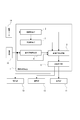
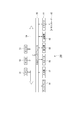
- FIG. 1 is a block diagram of an information processing apparatus that implements an image processing apparatus according to an embodiment. It is explanatory drawing of the trimming image of 1st Embodiment. It is explanatory drawing of the cut-out process of the trimming image of 1st Embodiment. It is a flowchart of the image editing process of 1st Embodiment. 12 is a flowchart of another example of the image editing process according to the first embodiment. It is explanatory drawing in the case of setting the threshold value which is the reference depth information of embodiment for every pixel.
- FIG. 1 shows a functional configuration of the image processing apparatus 1 according to the present disclosure and a peripheral configuration of the image processing apparatus 1.
- the image processing apparatus 1 includes an image acquisition unit 2, a depth acquisition unit 3, a reference depth setting unit 4, an image editing processing unit 5, and an image output unit 6.
- an operation unit 10 a display unit 11, a communication unit 12, a storage unit 13, and an image source 14 are illustrated.
- Each of the operation unit 10, the display unit 11, the communication unit 12, the storage unit 13, and the image source 14 may be provided in a device integrated with the image processing device 1, or may be a separate device and the image processing device 1. And may be connected by wired or wireless communication.
- the operation unit 10 detects various user operations for image editing.
- the operation unit 10 may be configured to detect an operation of an operator such as an actual key or switch, or may be configured to detect an operation such as a mouse, a keyboard, a voice input, a gesture input, or a non-contact input in a computer device. . Further, the operation unit 10 may be configured to detect a touch operation, a tap operation, or the like in the mobile terminal 101 such as a smartphone illustrated in FIG. 2A, for example.
- FIG. 2A shows a state where an image to be edited is displayed on the screen 102 in the portable terminal 101 on which the image processing apparatus 1 is mounted, for example.
- FIG. 2B shows a state where operation buttons 111 and a slide lever 110 for touch operation are further displayed on the screen 102. The user can perform various operations for image editing using the operation buttons 111 and the slide lever 110.
- the display unit 11 is a display unit that performs various displays for a user (such as a photographer). For example, an LCD (Liquid Crystal Display) or an organic EL (Electro-EL) provided in a housing of the apparatus including the image processing apparatus 1. Luminescence) A display device such as a display.
- the display unit 11 is an LCD or the like that forms the screen 102 of the portable terminal 101 or the like in FIG. 2A.
- the display unit 11 may be a separate display device from the apparatus having the image processing apparatus 1.
- the display unit 11 performs various displays for the user interface. For example, display of images (still images and moving images) generated by the image processing apparatus 1 through editing processing, display of images before editing (still images and moving images), and display of operation elements such as the operation buttons 111 and the slide lever 110 described above. And other necessary displays.
- the communication unit 12 performs communication with other devices by wired or wireless connection. For example, communication is performed by a communication method such as a wireless communication standard such as WIFI (Wireless Fidelity: registered trademark) or Bluetooth (registered trademark).
- the communication unit 12 performs communication of image data (still image file or moving image file) between external display devices, recording devices, playback devices, and the like, and as a network communication unit, for example, the Internet, home network, LAN It is also possible to perform communication through various networks such as (Local Area Network) and perform various data transmission / reception with servers, terminals, etc. on the network.
- the communication unit 12 transmits an image (still image or moving image) generated by the image processing apparatus 1 through editing processing to an external device.
- the communication unit 12 may receive image data used for editing processing from the outside.
- the storage unit 13 is composed of, for example, a non-volatile memory, and stores edited image data as an image file such as still image data or moving image data.
- the storage unit 13 may be a solid-state memory such as a flash memory built in the apparatus housing, a memory card (for example, a portable flash memory) that can be attached to and detached from the apparatus, and a card that performs recording / reproduction access to the memory card.
- the form by a recording / reproducing part may be sufficient.
- it may be realized as an HDD (Hard Disk Drive), an optical disk, a disk drive, and the like.
- the storage unit 13 stores edited image data generated by the image processing apparatus 1.
- the image data used by the image processing apparatus 1 for editing processing may be read from the storage unit 13.
- the storage unit 13 may store a program for causing a computer device to execute processing as the image processing apparatus 1.
- the image source 14 indicates that the image processing apparatus 1 is a supplier of image data used for editing processing. Image data as a still image or moving image to be processed is supplied from the image source 14 to the image processing apparatus 1.
- the communication unit 12 and the storage unit 13 may correspond to the image source 14.
- the image acquisition unit 2 in the image processing apparatus 1 acquires image data to be edited from the image source 14.
- the processing target is still image data selected by a user operation.
- the depth acquisition unit 3 detects pixel depth information for the image to be processed.
- depth information DP is added for each pixel to the image data to be edited by the image processing apparatus 1.
- the depth information DP is information on the depth position of the subject when an image is captured.
- image data (still image data) is composed of pixels (pixels) arranged in 0 rows to n rows and 0 columns to m columns, and ⁇ (m + 1) ⁇ (n + 1) ⁇ pixels PX0 ⁇ 0, PX0-1... PXn-m.
- Depth information DP0-0, DP0-1... DPn-m is added to each pixel PX0-0, PX0-1. Each is depth information when the subject of the pixel is imaged.
- the depth acquisition unit 3 detects depth information DP0-0, DP0-1... DPn-m from the image to be processed.
- each of the pixels PX0-0 to PXn-m shown in FIG. 3 may be considered as one pixel for each color such as an R pixel, a G pixel, and a B pixel, or an R pixel, a G pixel,
- the B pixels may be considered as one color pixel. That is, the depth information DP (DP0-0 to DPn-m) may be added in units of individual pixels or may be added in units of color pixel units. Further, although not shown, depth information DP may be added to each pixel block in which a plurality of pixels (or a plurality of color pixels) are collected.
- the depth acquisition unit 3 may receive and acquire depth information detected by other devices and sensors for image data to be processed, depth information registered in advance, and the like.
- the depth acquisition unit 3 may detect depth information arbitrarily set by the user.
- the reference depth setting unit 4 performs processing for setting reference depth information serving as a comparison reference for pixel depth information during image processing. As will be described in the processing of the first to fifth embodiments to be described later, the reference depth setting unit 4 uses a depth threshold th for image cropping as reference depth information (also simply referred to as “threshold th”). In addition, an insertion depth for inserting an image or the like (threshold value thI corresponding to the insertion depth), a depth reference value DPref that determines a depth position as a reference, and the like are set.
- the image editing processing unit 5 performs image editing processing using the reference depth information set by the reference depth setting unit 4 and pixel pixel depth information DP0-0 to DPn-m captured by the image acquisition unit 2 as processing targets. Do. As examples of the image editing process, trimming, various types of image synthesis, image effect addition, and the like will be described later.
- the image output unit 6 outputs image data as an edited image created by the image editing processing unit 5. That is, the image output unit 6 outputs the edited image data created by the editing process to the display unit 11 to display the editing result. Further, the image output unit 6 can also output the created edited image data to the communication unit 12 to be transmitted to an external device. The image output unit 6 can also output the created edited image data to the storage unit 13 and store it in the storage medium.
- the image processing apparatus 1 can perform various image editing described later and generate an edited image.
- Such an image processing apparatus 1 is realized by an information processing apparatus 100 having a hardware configuration as shown in FIG.
- the information processing apparatus 100 includes a CPU (Central Processing Unit) 51, a ROM (Read Only Memory) 52, and a RAM (Random Access Memory) 53.
- the CPU 51 executes various processes according to a program stored in the ROM 52 or a program loaded from the storage unit 59 to the RAM 53.
- the RAM 53 also appropriately stores data necessary for the CPU 51 to execute various processes.
- the CPU 51, ROM 52, and RAM 53 are connected to each other via a bus 54.
- An input / output interface 55 is also connected to the bus 54.
- the input / output interface 55 can be connected to a display 56 made up of a liquid crystal panel or an organic EL panel, an input unit 57 made up of a keyboard, a mouse, etc., a speaker 58, a storage unit 59 made up of an HDD, a communication unit 60, etc. is there.
- the display 56 means the display unit 11.
- the display unit 11 may be a separate device from the information processing apparatus 100, and in this case, the display 56 may be a separate device connected to the input / output interface 55.
- the input unit 57 in FIG. 4 means an input device used by a user who uses the information processing apparatus 100, and includes a function as the operation unit 10 in FIG. 1, for example.
- the communication unit 60 performs communication processing via a network including the Internet and communication with peripheral devices, and includes, for example, a function as the communication unit 12 of FIG.
- a drive 61 is connected to the input / output interface 55 as necessary, a memory card 62 is mounted, and a computer program read from the memory card 62 is installed in the storage unit 59 as necessary, or the CPU 51 The data processed in is stored.
- the drive 61 may be a recording / reproducing drive for a removable storage medium such as a magnetic disk, an optical disk, or a magneto-optical disk.
- the drive 61 and the memory card 62 also have a function as the storage unit 13 in FIG.
- processing as the image processing apparatus 1 of the embodiment that is, as the image acquisition unit 2, the depth acquisition unit 3, the reference depth setting unit 4, the image editing processing unit 5, and the image output unit 6 of FIG.
- these processes are realized by software activated by the CPU 51.
- the program constituting the software is downloaded from the network or read from the removable storage medium and installed in the information processing apparatus 100 in FIG.
- the program may be stored in advance in an HDD or the like as the storage unit 59. Then, when the program is started in the CPU 51, various image editing processes can be performed as will be described in detail later.
- the image processing apparatus 1 is not limited to a single information processing apparatus (computer apparatus) 100 having a hardware configuration as illustrated in FIG. 4, and a plurality of computer apparatuses are systematized. It may be configured.
- the plurality of computer devices may be systemized by a LAN or the like, or may be arranged at a remote place by a VPN (Virtual Private Network) using the Internet or the like.
- the plurality of computer devices may include a computer device that can be used by a cloud computing service.
- the information processing apparatus 100 in FIG. 4 can be realized as a stationary computer, a laptop computer, or a portable terminal such as a tablet terminal or a smartphone.
- the image processing apparatus 1 according to the present embodiment can be mounted on an electronic apparatus such as a television apparatus, a monitor apparatus, an image editing apparatus, or an imaging apparatus that has a function as the information processing apparatus 100.
- First Embodiment> As a first embodiment, an example of editing processing in which the image processing apparatus 1 trims a subject at an arbitrary depth using depth information will be described.
- subject extraction using depth information Explaining subject extraction using a virtual vertical plane, subject extraction using a virtual horizontal plane / virtual inclined plane, and subject extraction combining extraction using a virtual plane and image recognition will be described.
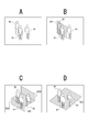
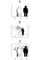
- FIG. 5A is an image of original image data to be processed. This is a still image in which three persons facing the front are captured as subjects H1, H2, and H3. Each of the three subjects H1, H2, and H3 has different standing positions in the depth direction during imaging.
- FIG. 6A shows a state in which the positions of the subjects H1, H2, and H3 at the time of imaging are viewed obliquely from above.
- the subject H1 is standing closest to the imaged camera, and the subject H2 is slightly behind.
- the subject H3 stands on the farthest side.
- the image processing apparatus 1 has the depth information DP for each pixel added to the image data.
- the position (depth) in the depth direction can be recognized.
- a threshold th for trimming is set as the reference depth information.
- the virtual vertical plane VP1 in FIG. 6B is assumed based on the threshold th, and the subject is cut out before and after (front side / back side) of the virtual vertical plane VP1.
- FIG. 6B shows the virtual vertical plane VP1 when the depth value set as the threshold th is larger than the depth value of the subject H1 and smaller than the depth value of the subject H2.
- the image processing apparatus 1 sets the threshold th, compares the depth information DP of each pixel with the threshold th, and determines whether or not to display a pixel based on the comparison result, thereby determining the threshold th.
- the subject on the front side (or the back side) of the virtual vertical plane VP1 with the depth set in step 3 can be trimmed.
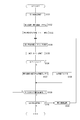
- FIG. 7 shows a processing example of the image processing apparatus 1.
- 7 is a process executed by the CPU 51 of FIG. 4 having each function (mainly functions as the reference depth setting unit 4 and the image editing processing unit 5) of the image processing apparatus 1 shown in FIG. .
- the processing by each function of the image processing apparatus 1 is the same in the flowcharts of FIGS. 8, 12, 15, 17, 19, 23, 25, and 28 described later. is there.
- the same steps as those in the flowcharts already described are denoted by the same step numbers, and redundant description is avoided.
- the image processing apparatus 1 identifies an image to be processed in step S101 in FIG. For example, as the image data acquired by the image acquisition unit 2, image data as shown in FIG.
- the image processing apparatus 1 sets a threshold th as reference depth information. That is, a value at a certain depth is set as a threshold th.
- the image processing apparatus 1 sets the value of the threshold th according to the operation information input from the operation unit 10.
- the slider 110 in FIG. 2B is an operator for setting the threshold th.
- the user moves the slider 110 to an arbitrary position by a touch operation. By making the position of the slider 110 represent the depth, the user can input an arbitrary depth.
- various operation modes for designating the threshold th can be considered. It is also assumed that when the user touches the subject on the screen 102, the depth in front of the subject becomes the threshold th, and the user can input a numerical value as the depth.
- the image processing apparatus 1 After setting the threshold th, the image processing apparatus 1 sequentially selects each pixel PX of the image data to be edited in step S103 and subsequent steps, and compares it with the threshold th. That is, the image processing apparatus 1 (image editing processing unit 5) specifies one pixel PX in step S103, and specifies depth information DP of the pixel PX in step S104. Note that the depth acquisition unit 3 detects the depth information DP0-0 to DPn-m of each pixel PX0-0 to PXn-m of the image data to be processed acquired by the image acquisition unit 2 from, for example, image data. The image editing processing unit 5 acquires the depth information DP of the corresponding pixel PX from the depth acquisition unit 3. In addition, when the depth information DP is added to the depth information DP in units of color pixels or pixel blocks, one color pixel and pixel block may be specified in step S103.
- step S105 the image processing apparatus 1 (image editing processing unit 5) compares the depth information DP of the target pixel PX with the threshold th. If DP ⁇ th, the pixel PX is a pixel of the subject on the near side of the depth that is the value of the threshold th. Therefore, in this case, the image processing apparatus 1 proceeds to step S107, and sets the pixel PX as a pixel to be displayed as it is even in the edited image data. If DP ⁇ th is not satisfied, the pixel PX is a pixel of the subject on the back side after the depth that is the value of the threshold th. Therefore, in this case, the image processing apparatus 1 proceeds to step S106 and replaces the image data value of the pixel PX with another pixel data value on the edited image data. For example, it is replaced with a specific pixel value used as mask data.
- step S108 the image processing apparatus 1 confirms whether or not the above processing is completed for all the pixels PX0-0 to PXn-m of the image data to be processed. If not completed, the process returns to step S103, the pixel PX to be processed next is specified, and the processes of steps S104 to S107 are similarly performed.
- the edited image data as shown in FIG. 5B is generated by trimming the subject in front of the virtual vertical plane VP1. . That is, by using the depth information DP, a trimmed image corresponding to the subject position at the time of imaging is realized.
- the edited image data generated in this way is displayed on the display unit 11 by being output by the image output unit 6, transferred to an external device by the communication unit 12, or stored in a storage medium by the storage unit 13. .
- the example in FIG. 5B is an image in which the entire body of the subject H1 is cut out, but various expressions are possible, for example, depending on the posture of the person of the subject H1 and the threshold th in the original image data. For example, it is possible to generate an image in which only the front side of the subject H1 is extracted, or an image in which only the upper body is pulled out of the wall when the subject H1 is bent forward in the original image.
- step S105 if DP> th, the process proceeds to step S107, and if DP> th, the process proceeds to step S106 to obtain a trimmed image in which a subject on the back side from the virtual vertical plane VP1 is extracted.
- the mask data is the luminance / color of the background pixel of the trimmed subject, but it may be a fixed value that represents a predetermined luminance / color.
- the brightness and color may be selected by the user through an operation.
- FIG. 6C shows a state in which a virtual horizontal plane VP2 is assumed in a space where subjects H1, H2, and H3 are present.
- the vertical plane VP2F in front of the virtual horizontal plane VP2 is shown as a plane having a depth of 0, and the vertical plane VP2R behind is shown as a plane having a maximum depth.
- FIG. 6D shows a state in which a virtual inclined surface VP3 is assumed in a space where the subjects H1, H2, and H3 are present.
- edited image data in which the image above the virtual horizontal plane VP2 is trimmed as shown in FIG. 5C can be generated.
- edited image data in which an image below the virtual horizontal plane VP2 is trimmed can also be generated.
- edited image data in which the image above the virtual inclined plane VP3 is trimmed as shown in FIG. 5D can be generated. it can.
- edited image data in which an image below the virtual inclined plane VP3 is trimmed can also be generated.
- an edited image an image in which the subject floats on the water surface, an image in which the subject jumps out of the wall surface, or the subject is buried in the ground due to the background color or background image other than the trimmed portion and the cropped portion. It is possible to perform image representation such as an image and an image in which a subject is submerged in water.
- Trimming based on these virtual horizontal plane VP2 and virtual inclined plane VP3 can be realized by setting the threshold th.
- a certain value is set as the threshold th in FIG. 7
- the trimming is performed assuming the virtual vertical plane VP1.
- the threshold th for each pixel or each region, trimming assuming the virtual horizontal plane VP2 and the virtual inclined plane VP3 is possible.
- a threshold th serving as reference depth information is set.
- the image processing apparatus 1 sets a plurality of threshold values th0-0 to th (nm) so as to correspond to the pixels PX0-0 to PXn-m, respectively.
- FIG. 9A shows an example in which threshold values th0-0 to th (nm) corresponding to the pixels PX0-0 to PXn-m are set.
- various virtual planes can be assumed depending on the threshold values th0-0 to th (nm) corresponding to the pixels PX0-0 to PXn-m.
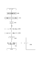
- the image processing apparatus 1 After setting the threshold th (in this case, the thresholds th0-0 to th (nm)), the image processing apparatus 1 identifies one pixel PX in step S103, and in step S110A, the threshold corresponding to the pixel PX. Specify th. For example, when the pixel PX0-0 is first specified as a processing target, the threshold th0-0 among the thresholds th0-0 to th (nm) set in step S102A is specified. In step S104, the image processing apparatus 1 specifies the depth information DP of the specified pixel PX.
- step S105A the image processing apparatus 1 compares the depth information DP of the pixel PX with the corresponding threshold th (for example, the depth information DP of the pixel PX0-0 and the threshold th0-0). If DP ⁇ th, the pixel PX is a pixel of the subject on the near side of the depth that is the value of the threshold th. Therefore, in this case, the image processing apparatus 1 proceeds to step S107, and sets the pixel PX as a pixel to be displayed as it is even in the edited image data. If DP ⁇ th is not satisfied, the pixel PX is a pixel of the subject on the back side after the depth that is the value of the threshold th. Therefore, in this case, the image processing apparatus 1 proceeds to step S106, and replaces the pixel data value of the pixel PX with another pixel data value on the edited image data. For example, it is replaced with a specific pixel value used as mask data.
- step S108 the image processing apparatus 1 checks whether or not the above processing has been completed for all the pixels PX0-0 to PXn-m of the image data to be processed.
- the pixel PX to be specified is specified, and the processing in steps S110A to S107 is performed in the same manner.
- the subject on the upper side of the virtual horizontal plane VP2 and the front side of the virtual inclined plane VP3 is trimmed, as shown in FIGS. 5C and 5D.
- Image data is generated.
- the edited image data generated in this way is displayed on the display unit 11 by being output by the image output unit 6, transferred to an external device by the communication unit 12, or stored in a storage medium by the storage unit 13. .
- trimming assuming various virtual surfaces can be performed depending on the setting of the thresholds th0-0 to th (nm).
- threshold values th0-0 to thk-m corresponding to the pixels PX0-0 to PXk-m from the 0th row to the kth row, which are the upper half of the image All have the same value thU.
- the threshold values thk + 1-0 to thn-m corresponding to the pixels PXk + 1-0 to PXn-m from the (k + 1) th row to the nth row which are the lower half of the image are all set to the same value thL.
- the virtual horizontal plane VP2 in FIG. 6C can be set. That is, since the upper part of the image is a pixel on the near side of the threshold th, it is left as a pixel on the edited image data, and the lower part of the image is masked because it is a pixel on the back side of the threshold th. As a result, an edited image that is cut out on the virtual horizontal plane VP2 is generated.
- the height position at which the virtual horizontal plane VP2 is arranged can also be set arbitrarily.
- the image processing apparatus 1 is assumed to set the k value according to the operation information input from the operation unit 10.
- the slider 110 in FIG. 2B is an operator for setting the k value.
- the user can designate at which height position in the image the virtual horizontal plane VP2 is to be arranged.
- various operation modes for designating the k value can be considered.
- the height position may be the virtual horizontal plane VP2, or the numerical value as the height position may be input by the user.
- the threshold value th is set to the same value for pixels in the same row as shown in FIG. 10A.
- the threshold values th0-0 to th0-m corresponding to the pixels PX0-0 to PX0-m in the first row are set to the same value thR0.
- the thresholds th1-0 to th1-m corresponding to the pixels PX1-0 to PX1-m in the second row are set to the same value thR1.
- the thresholds thn-0 to thn-m corresponding to the pixels PXn-0 to PXn-m in the last row are set to the same value thRn.
- the virtual inclined plane VP3 in FIG. 6D can be set.
- the edited image data of FIG. 5D can be generated by the processing of FIG.
- the user may be able to set the inclination angle.
- the image processing apparatus 1 sets the depth value for each row from the value thR0 to the value thRn so that the inclination angle is set according to the operation information input from the operation unit 10.
- the tilt angle can be changed by variably setting the difference.
- the image processing apparatus 1 may be adapted to the user's operation of the slider 110, touch operation, input operation of the tilt angle numerical value, and the like.
- the threshold value th is set to the same value for pixels in the same column.
- the thresholds th0-0 to thn-0 corresponding to the pixels PX0-0 to PXn-0 in the first column are set to the same value thC0.
- the thresholds th0-1 to thn-1 corresponding to the pixels PX0-1 to PXn-1 in the second column are set to the same value thC1.
- the thresholds th0-m to thn-m corresponding to the pixels PX0-m to PXn-m in the last column are set to the same value thCm.
- the value thC0 is set to the deepest value, and the depth is gradually decreased from the value thC1 to the value thCn.
- An inclined surface can be set. In that case, an edited image in which the mask portion increases as the subject on the right side is generated by the processing of FIG. Further, by setting the value thC0 as the shallowest value and setting the depth to gradually increase from the value thC1 to the value thCn, a virtual inclined surface that exists from the left front side to the right back side of the screen is obtained. Can be set. In that case, an edited image in which the mask portion increases as the subject on the left side is generated by the processing of FIG.
- the image processing apparatus 1 sets the values of thC0 to thCm corresponding to the user's operation of the slider 110, touch operation, input operation of the inclination angle value, and the like. It is preferable that the tilt angle in the left-right direction can be set by the user.
- step S105A if DP> th in step S105A, the process proceeds to step S107, and if DP> th, the process proceeds to step S106.
- a trimmed image with the reverse can be generated.
- various pixel values used as mask data in step S106 can be considered.
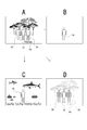
- FIG. 11A is an original image to be processed. This is a still image in which three persons facing the front are imaged as subjects H1, H2, and H3, and the surrounding scenery is shown in front and behind each person.
- the subject H1 which is the person on the front side
- the subject H4 is also included in the trimmed image.
- a trimmed image in which only a subject H3 that is a person is cut out can be generated, for example, as shown in FIG. 11B. .
- FIG. 12 shows a processing example of the image processing apparatus 1.
- the image processing apparatus 1 specifies the image to be processed in step S101 of FIG. 12, subsequently, the subject designation information is acquired in step S120.
- the image is displayed on the screen 102 in FIG. 2B, and the subject at the position touched on the screen 102 by the user is acquired as subject designation information. It is assumed that the user touches the area of the subject H1.
- the image processing apparatus 1 image editing processing unit 5 acquires this operation information (touch position information).
- the image editing processing unit 5 can perform image analysis on the image to be processed. For example, a specific subject recognition such as person recognition or face recognition can be performed to determine the pixel region of the subject.
- a specific subject recognition such as person recognition or face recognition
- the determined subject is presented. For example, on the screen 102, a display for presenting the determined subject (a frame display for enclosing a person portion or the like) is performed.
- the user can specify any of the recognized subjects by a touch operation. For example, when the information on the touch position is acquired, the image editing processing unit 5 recognizes that the person is designated if the position is within the range of the person determined by person recognition or the like.
- the image editing processing unit 5 determines the contour of the pixel at the position in the subject image, and determines the region in the contour. You may make it recognize as the area
- a specific subject is designated by a user operation or the like. Alternatively, a specific subject such as a person may be automatically specified regardless of the user's operation.
- step S102 the image processing apparatus 1 sets a threshold th that assumes the virtual vertical plane VP1 according to, for example, a user operation. Then, steps S103, S104, and S105 are performed in the same manner as in FIG. In FIG. 12, the depth information DP of the pixel PX is compared with the threshold th in step S105, and if DP ⁇ th, in step S122, whether or not the pixel PX is the subject pixel specified in step S120. To check. If it is a pixel of the designated subject, the process proceeds to step S107, and the pixel PX is set as a pixel to be displayed as it is in the edited image data.
- step S121 the image processing apparatus 1 performs replacement and effect processing on the pixel data of the pixel PX. For example, it is replaced with mask data as in FIG.
- step S108 Such a process is repeated until it is determined in step S108 that all pixels are finished. Thereby, more accurate trimming can be performed.
- step S122 the process proceeds to step S121 for the pixel of the subject H4. Replaced with data.
- a trimmed image obtained by cutting out only the subject H1 can be generated as shown in FIG. 11B. That is, it is possible to perform image editing that accurately cuts out only the target to be trimmed.
- effect processing may be performed as well as replacement with mask data.
- monochrome processing is performed.
- FIG. 11D it is possible to generate an edited image in which only the subject H1 of the foremost person to be cut out is left as a color image and the other subjects are monochrome images (gray in FIG. 11D).
- the part is assumed to be monochrome).
- shape recognition, object recognition, color recognition, etc. only a specific subject is left in the color image, and other subjects are not mixed in color even if they are in the position to be trimmed. Can be processed.
- trimming and effect processing can be performed in which a specific subject is accurately distinguished from other subjects.
- step S121 not only monochrome but also a change in color, a change in luminance, a blurring process, a mosaic process, a multiple exposure process, and the like can be considered.
- step S121 a process may be performed in which a pixel value at a corresponding pixel position in a completely different image is replaced. Then, it is possible to obtain an edited image in which the cut out subject H1 is captured in another background.
- the subject H1 can be cut out from the image of FIG. 11A and an edited image can be generated as if it was placed in a different background as shown in FIG. 11C.
- the trimming process using the designation of the subject as shown in FIG. 12 can naturally be applied to the case where the virtual horizontal plane VP2 or the virtual inclined plane VP3 is used. Furthermore, by applying the image effect processing in step S121 and the replacement of other images with pixel values when the virtual horizontal plane VP2 or the virtual inclined plane VP3 is used, more various image representations are possible.
- Second Embodiment> As a second embodiment, an example of an editing process in which the image processing apparatus 1 uses the depth information to naturally adapt the graphical effect to the space will be described.
- a character or graphic without depth is combined with an image with depth. That is, when characters or graphics are added to the captured image, a more natural expression can be realized by adjusting the overlap with the subject using the depth information.
- FIG. 13A shows an example of a captured image to be processed (first image). This is the same image as in FIG. 5A.
- FIG. 13B illustrates “ABCDE” in a certain typeface as an example of characters / graphics inserted into the first image as the second image.
- the character / graphic of FIG. 13B is synthesized with the image of FIG. 13A.
- a threshold thI indicating the insertion depth is set as the reference depth information.
- the threshold thI as the insertion depth is a depth value at which characters / graphics are inserted into the image of FIG. 13A.
- the threshold thI is set to a depth value on the back side of the subject H1 and on the near side of the subject H2. As shown in FIG.
- the insertion area IA is determined at this insertion depth. Then, the characters / graphics of “ABCDE” are synthesized so as to be inserted into the insertion area IA. As a result, a composite image as shown in FIG. 13D is generated.
- the insertion area IA is the position of the threshold thI as the insertion depth and is behind the subject H1, so that a part of “ABCDE” is hidden behind the subject H1.
- FIG. 14A shows an example of a captured image to be processed as in FIG. 13A.
- FIG. 14B illustrates, for example, five heart marks as examples of characters / graphics to be inserted. For example, it is an example of a graphic created by CG (computer graphics). 14B is combined with the image of FIG. 14A.
- threshold values thI1 to thI5 indicating the insertion depths of the five heart marks are set as the reference depth information.
- the insertion areas IA1 to IA5 of each heart mark are set.
- the insertion areas IA1 to IA5 are areas having depths indicated by threshold values thI1 to thI5, respectively.
- the threshold thI1 is the depth before the subject H1
- the threshold thI2 is the depth behind the subject H1 and before the subject H2
- the threshold thI3 is the depth behind the subject H2 and before the subject H3, the threshold thI4.
- thI5 is a depth on the back side of the subject H3.
- the five heart mark characters / graphics are synthesized so as to be inserted into the insertion areas IA1 to IA5, respectively.
- a composite image as shown in FIG. 14D is generated.
- Each heart mark is an image that may or may not be visible depending on the context of the subjects H1, H2, and H3 so that the heart mark exists at a depth set by the thresholds thI1 to thI5.
- FIG. 15 shows a processing example for realizing such editing processing.
- the image processing apparatus 1 identifies the first image to be processed in step S131 of FIG. For example, image data as shown in FIG. 13A or FIG. 14A is processed as image data acquired by the image acquisition unit 2.
- the image processing apparatus 1 specifies a second image (inserted image) to be inserted into the first image. For example, it is a character / graphic as shown in FIGS. 13B and 14B.
- the identification of the first and second images is performed according to the user's image designation operation.
- step S133 the image processing apparatus 1 sets an insertion area IA into which the second image (inserted image) is inserted on the first image, and sets a threshold thI as reference depth information.
- a threshold thI as reference depth information.
- one insertion area IA and a threshold thI as its insertion depth are set.
- a plurality of insertion areas IA1 to IA5 and thresholds thI1 to thI5 as respective insertion depths are set.
- This setting may be determined according to the position designated on the first image by the user, for example. For example, it is set so that a character / graphic is inserted immediately before the subject at the position designated by the user on the first image.
- the insertion area IA of the second image in FIG. 13B is arranged in front of the subject H2.
- the insertion area IA1 of the first heart mark is set at the depth (threshold thI1) on the near side of the subject H1.
- thresholds thI2 to thI5 are set to depths corresponding to the sizes (for example, depths that gradually become deeper). Note that the insertion area IA and the threshold thI may be automatically set by the image processing apparatus 1 without being specified by the user.
- step S134 and subsequent steps the image processing apparatus 1 sequentially compares each pixel PX included in the insertion area IA with the threshold thI on the image data of the first image. That is, in step S134, the image processing apparatus 1 specifies one pixel PX in an area that is an insertion area IA in the first image, and specifies depth information DP of the pixel PX in step S135.
- the set insertion area IA is plural (for example, the insertion areas IA1 to IA5), for example, one of the pixels in the first insertion area IA1 is specified as a processing target.
- step S136 the image processing apparatus 1 compares the depth information DP of the target pixel PX with the threshold value thI set for the insertion area IA including the pixel PX. If DP ⁇ thI, the pixel PX in the first image is a subject pixel in front of the depth that is the value of the threshold thI. Therefore, the image processing apparatus 1 proceeds to step S138, and sets the pixel PX as a pixel to be displayed as it is on the edited image data. If DP ⁇ thI is not satisfied, the pixel PX in the first image is a pixel of a subject on the back side after the depth that is the value of the threshold thI.
- the image processing apparatus 1 proceeds to step S137 and replaces the pixel data value of the image PX with the pixel data value corresponding to the pixel position in the second image (inserted image) on the edited image data. . That is, it is set as a pixel for displaying pixel data of the second image.
- step S139 the image processing apparatus 1 confirms whether or not the above processing has been completed for all the pixels of the first image in the region set as the insertion position IA. If not completed, the process returns to step S134 to specify the pixel PX to be processed in the next insertion area IA that is currently processed, and the processes of steps S135 to S138 are similarly performed. If it is determined in step S139 that the processing in steps S134 to S138 has been completed for all pixels in one insertion area IA, the image processing apparatus 1 checks in step S140 whether there is another insertion area IA set. To do. When one insertion area IA is set as shown in FIG. 13C, the process is finished. When a plurality of insertion areas IA1 to IA5 are set as shown in FIG.
- step S141 the next insertion area IA (for example, insertion area IA2) is selected in step S141. Then, the processing of steps S134 to S139 is performed for the insertion area IA. When it is confirmed in step S140 that the processing has been completed for all the insertion areas IA, the processing in FIG. 15 is finished.
- edited image data as shown in FIGS. 13D and 14D is generated, for example.
- the edited image data generated in this way is displayed on the display unit 11 by being output by the image output unit 6, transferred to an external device by the communication unit 12, or stored in a storage medium by the storage unit 13. .
- a character / graphic as a second image is inserted at a predetermined depth with respect to the first image, and the character / graphic is actually present in the subject space.
- a composite image is realized. In other words, by using the depth information and adjusting the overlap, it is possible to create an image expression that naturally adapts the graphical effect to the subject space.
- the image in FIG. 16A is a first image in which three subjects H1, H2, and H3 are captured.
- second images G1 and G2 each having the letters “ABCD” are inserted in a depth relationship as shown in FIG. 16B.
- the depth of the second image G1 is between the subjects H1 and H2
- the depth of the other second image G2 is between the subjects H2 and H3.
- FIG. 16C shows an edited image in which the second images G1 and G2 are inserted in the arrangement state in the depth direction, and further image processing is performed to express the sense of blur in the depth direction.
- an original image having no depth as a character / graphic can be naturally added to the first image. It is possible to make a composite image that fits in.
- FIG. 17 shows a processing example.
- FIG. 17 is an example in which step S137 in the processing example of FIG. 15 is changed to steps S142 and S143.
- the processing in steps S131 to S136 is the same as that in FIG.
- the image processing apparatus 1 compares the depth information DP of the target pixel PX with the threshold thI set for the insertion region IA including the pixel PX. If DP ⁇ thI, the pixel PX in the first image is a pixel of the subject on the near side of the depth that is the value of the threshold thI, and thus the process proceeds to step S138, and the image data after editing the pixel PX Set the pixel to display as it is above.
- the image processing apparatus 1 proceeds to step S142 and replaces the pixel data value of the image PX with the pixel data value corresponding to the pixel position in the second image (inserted image) on the edited image data. . That is, the pixel data of the second image is selected.
- step S143 an image effect corresponding to the depth (that is, the set value of the threshold thI) is applied to the pixel data of the second image. For example, processing is performed to reduce the luminance value so as to match the depth position or to give a sense of blur.
- Steps S139, S140, and S141 are the same as those in FIG.
- the image effect processing in step S143 is preferably executed for the range of the second image at the time after step S139 when the pixel arrangement of the second image is finished for the insertion area IA. In some cases.
- a character / graphic having no depth as a second image can be synthesized with an image effect corresponding to the insertion position in the first image, and a synthesized image very familiar to the first image, that is, It is possible to generate a composite image that looks like a character / graphic as if it existed when the first image was actually captured.
- a character / graphic synthesis has been described. However, for example, when natural phenomena such as fog, clouds, and flare are synthesized with an image, in addition to overlapping with the subject of the first image using the depth information, the density is also reduced. Natural expressions including these can be realized.
- the floating object is also reflected according to the insertion position and the depth information DP of the pixel of the first image. Also, shades are set according to the depth. Thereby, a composite image can be created as a more natural scene. Further, when a shadow, a light ray, a shadow of a subject, or the like due to virtual illumination light is combined as the second image, it can be appropriately expressed according to the depth.
- Third Embodiment> As a third embodiment, an example of an editing process in which the image processing apparatus 1 adds image effects using depth information will be described. That is, an image effect such as an optical effect corresponding to the depth is added to the subject of the image to be processed.
- FIG. 18A shows the positional relationship between the subjects H1, H2, and H3 when an image to be processed is captured.
- the subjects H1, H2, and H3 are sequentially arranged from the front side.
- an edited image as shown in FIG. .
- the images are such that the subjects H1, H2, and H3 are standing in the fog.
- an image effect by setting an effect level according to the depth of the subject, it is possible to realize an image effect expression according to the depth position of the subject as in this example.
- an image effect that adds an effect such as fog or rain an image that can be said to be optical meteorological phenomenon emulation can be generated by changing the density and density according to the depth of the subject.
- FIG. 19 shows a processing example.
- the image processing apparatus 1 specifies an image to be processed in step S150 of FIG. For example, as the image data acquired by the image acquisition unit 2, image data as shown in FIG. In step S151, the image processing apparatus 1 performs image effect setting to be performed on the image to be processed. In other words, what kind of image effect is applied is set. In practice, the type of image effect may be selected according to the user's operation.
- the image processing apparatus 1 sets the depth reference value DPref as the reference depth information.
- the depth reference value DPref indicates a depth serving as a reference for the image effect level (effect intensity).
- FIG. 20 shows that the lens surface of the camera at the time of capturing an image to be processed is the position LP, and a certain depth position is the depth reference value DPref.
- the depth of the depth reference value DPref may be, for example, the focal length of the camera or the depth selected by a user operation.
- a certain depth is set as a reference depth of the image effect level.
- step S153 and subsequent steps the image processing apparatus 1 sequentially performs processing on each pixel PX of the image data to be processed. That is, the image processing apparatus 1 specifies one pixel PX in step S153, and specifies depth information DP of the pixel PX in step S154.
- the image effect level EP is obtained by multiplying the initial value EPd of the image effect level by the difference (DP ⁇ DPref).
- step S157 image effect processing is performed using the image effect level EP. For example, when an effect such as fog is applied to the image, the fog density is set at the image effect level EP.
- step S158 the pixel value subjected to the image effect processing is set as pixel data used for the edited image.
- the subjects OB1, OB2, and OB3 are shown as depths from the lens surface LP, but these depths are DP1, DP2, and DP3, respectively.
- the depth reference value DPref DP1.
- the image effect process is not performed or the image effect process is performed with the initial value.
- the subject OB2 is subjected to image effect processing at a level of initial value EPd ⁇ difference (DP2-DPref).
- the subject OB3 is subjected to image effect processing at a level of initial value EPd ⁇ difference (DP3-DPref). If the depths of the subjects OB1, OB2, and OB3 correspond to the subjects H1, H2, and H3 in FIG. 18A, respectively, the subject H1 is clear as shown in FIG. Accordingly, an edited image is realized with an image effect that is unclear.
- step S159 of FIG. 19 the image processing apparatus 1 confirms whether or not the above processing has been completed for all the pixels of the processing target image. If not completed, the process returns to step S153, the pixel PX to be processed next is specified, and the processes of steps S154 to S158 are similarly performed.
- step S159 that the processing in steps S153 to S158 has been completed for all pixels, the processing in FIG.
- edited image data as shown in FIG. 18C has been generated, for example.
- the edited image data generated in this way is displayed on the display unit 11 by being output by the image output unit 6, transferred to an external device by the communication unit 12, or stored in a storage medium by the storage unit 13. .
- the shape and material of the walls and floors can be taken into account, and the amount of light, intensity, angle, color, etc. can be changed to express appropriate light.
- an image in which highlights and shadows are changed can be generated by changing the position and intensity of lighting.
- an image to be processed is simulated as a three-dimensional space using the depth DP, and a three-dimensional position of a light source for performing virtual lighting is set in the space.
- the depth position of the light source as the depth reference value DPref
- the influence of lighting from the light source on each subject luminance and shadow
- the lighting effect can be set according to the comparison between the depth information of each pixel and the depth reference value DPref.
- the user can arbitrarily set the position of the light source to generate an edited image that expresses various lighting situations.
- various image representations are possible by giving an image effect corresponding to the depth of the subject to the image to be processed.
- Fourth Embodiment> As a fourth embodiment, an example of an editing process in which the image processing apparatus 1 superimposes different images having depth information will be described. This is an example in which natural overlaying and image effects are applied to a plurality of images having a depth according to the depth of the subject.
- FIG. 21A is a first image. It is a group photo of many people. A certain person shown with diagonal lines is defined as a subject H10.
- FIG. 21B is a second image. It is a photograph of one person (subject H20). The subjects H10 and H20 have different image sizes (pixel area areas).
- the subject H20 is synthesized by adjusting the scale diagonally behind the subject H10 in the first image.
- an insertion area IA that is obliquely behind the subject H10 of the first image is set.
- the size of the subject H20 of the second image is reduced so that a scale feeling equivalent to that of the subject H10 can be obtained as shown in FIG. 21D.
- the positional relationship is such that the subject H20 exists in the insertion area IA set obliquely behind the subject H10.
- FIG. 21E shows a synthesized edited image. The subject H20 is inserted into the first image after the front-rear relationship with the subject H10 is expressed and the size is adjusted.
- FIG. 22A shows a second image (the image to be loaded) as the subject H40 trimmed from an image.
- FIG. 22B is a first image (inserted image) including the subject H30.
- the edited image in FIG. 22C is obtained by resizing the first image and performing composition such that the subject H40 of the second image is arranged in the first image.
- an image representation is performed in which the subject H40 of the second image that is a person in a sitting posture sits on the stepped portion of the subject H30 of the container that is the enlarged first image.
- an image in which the composite position is set is generated according to the depth of each pixel based on the real three-dimensional shape of the subject H30 and the depth information of each pixel in the posture of the subject H40 in which the person is sitting.
- FIG. 23 shows a processing example for realizing such editing processing.
- the image processing apparatus 1 identifies the first image to be processed in step S170 of FIG. In step S171, the image processing apparatus 1 also specifies the second image to be processed. Both the first image and the second image are image data acquired by the image acquisition unit 2 according to, for example, a user's image designation operation.
- the image processing apparatus 1 sets the insertion area IA for combining the first image and the second image, and the threshold thI as reference depth information (insertion depth). For example, as shown in FIG. 21C, the insertion area IA and the threshold thI as the insertion depth are set in the first image. These may be determined, for example, according to the position designated by the user on the first image. Alternatively, the image processing apparatus 1 may automatically set the insertion area IA and the insertion depth. For example, in FIG. 21C, the position and depth at which the subject H20 can be inserted may be automatically determined and set. In the example shown in FIG.
- the user may set the insertion area IA and the threshold thI as the insertion depth in the first image, and the image processing apparatus 1 uses the pixels of the subjects H30 and H40.
- the insertion area IA and the insertion depth may be automatically set based on the depth.
- step S173 the image processing apparatus 1 temporarily superimposes the first image and the second image after adjusting one or both sizes. For example, the size of the subject H20 is changed so that the subject H20 in FIG. 21B can be placed in the insertion area IA of the first image. Then, the subject H20 of the second image is overlaid on the insertion area IA of the first image.
- step S174 and subsequent steps the image processing apparatus 1 performs processing according to the overlapping relationship with the second image on all the pixels of the image data of the first image on the side where the subject is inserted. That is, the image processing apparatus 1 identifies one pixel PX of the first image in step S174, and determines whether or not the pixel PX is an overlapping pixel with the insertion subject (for example, subject H20) of the second image in step S175. to decide. If it is not an overlapping pixel, the process returns to step S174 via step S178 and proceeds to the processing of the next pixel.
- the image processing apparatus 1 identifies one pixel PX of the first image in step S174, and determines whether or not the pixel PX is an overlapping pixel with the insertion subject (for example, subject H20) of the second image in step S175. to decide. If it is not an overlapping pixel, the process returns to step S174 via step S178 and proceeds to the processing of the next pixel.
- the image processing apparatus 1 proceeds from step S175 to S176, and determines the context.
- the second image is inserted at the insertion depth indicated by the threshold thI. Therefore, in step S176, the image processing apparatus 1 may acquire the depth information of the pixel PX and compare the depth DP with the threshold value thI. If DP> thI, the pixel of the first image is on the near side. If DP> thI, it is determined that the pixel of the second image is the near side.
- the threshold thI as the insertion depth is, for example, the position closest to the subject H20, and the depth value DPs of the pixel closest to the constituent pixels of the subject H20 is the insertion depth (threshold thI). More preferably. For example, if the value of the depth information DP added to each pixel of the subject H20 of the second image is “DPx”, the comparison is performed according to the depth DPx of the pixel. That is, If DP> thI + (DPx ⁇ DPs), the pixel of the first image is on the near side.
- step S177 the image processing apparatus 1 selects the pixel on the near side as a pixel to be displayed. Thereby, when the first image and the second image are superimposed, one of the pixels is selected so that a portion on the near side is displayed.
- step S178 the image processing apparatus 1 confirms whether or not the above processing has been completed for each pixel of the first image. If not completed, the process returns to step S174, the pixel PX to be processed next is specified, and the processes of steps S175 to S177 are similarly performed. If it is determined in step S178 that the processing in steps S174 to S177 has been completed for all pixels of the first image, the image processing apparatus 1 proceeds from step S178 to S179.
- Step S179 is not necessarily performed, but here, the image processing apparatus 1 is an example of performing image effect processing according to the depth of the synthesized image. For example, a shadow generated by inserting a subject as the second image into the first image is added, or the second image is blurred according to the insertion depth.
- FIG. 22C shows an example in which image effect processing is performed so that the shadow SDW of the subject H40 in the second image appears on the first image.
- edited image data as shown in FIGS. 21E and 22C has been generated, for example.
- the edited image data generated in this way is displayed on the display unit 11 by being output by the image output unit 6, transferred to an external device by the communication unit 12, or stored in a storage medium by the storage unit 13. .
- the subject as the second image is inserted at a predetermined depth with respect to the first image. Also, the size of the subject at the time of insertion is adjusted. As a result, when the first image is actually captured, a composite image in which the subject of the second image is present in the space of the first image is realized. If image effect processing according to the insertion depth of the second image is performed, more natural composition is possible.
- the size adjustment may be a size relationship that fits in reality as shown in FIG. 21E, for example, or a size relationship that is impossible in reality as shown in FIG. 22C.
- the second image is the subject H40 trimmed from the original image as shown in FIG. 22A
- the degree of freedom of the overlapping area with the first image increases, or the number of pixels PX determined as overlapping pixels in step S175 is small. Therefore, the effect that the processing load of FIG. 23 is reduced can also be obtained.
- the first image and the second image are images having depth information, but are not limited to images actually captured.
- one or both of the first image and the second image may be a 3D graphic image having depth information of a subject or a pixel.
- FIG. 22A is an actually captured image
- FIG. 22B is a 3D graphics image
- a composite image as shown in FIG. 22C is generated using the respective depth information.
- FIG. 24 shows an example in which an image that expresses a contour line or a shadow box-like image is generated by cutting out pixels at several depths, flattening them, and recombining them.
- FIG. 24A shows a state in which an image to be processed including the subject H50 is trimmed with the virtual vertical plane VP11.
- FIG. 24B, FIG. 24C, FIG. 24D, and FIG. 24E show how the images to be processed are trimmed on the virtual vertical planes VP12, VP13, VP14, and VP15. These virtual vertical planes VP11 to VP15 are set to different depths.
- FIG. 24F, FIG. 24G, FIG. 24H, FIG. 24I, and FIG. Planarization is to equalize the depth of the cut out pixels. Then, the flattened images are synthesized so as to overlap each other. As a result, a shadow box-like edited image can be generated like the subject H50 ′ in FIG.
- FIG. 25 shows a processing example.
- the image processing apparatus 1 specifies an image to be processed.
- the image processing apparatus 1 sets thresholds th1 to th (p) as reference depth information.
- the thresholds th1 to th (p) are values for setting the trimming depths as in the virtual vertical planes VP11 to VP15.
- FIG. 26A An example of setting the threshold th is shown in FIG. 26A.
- several thresholds th1 to th7 are set for the depth from 0 to the maximum depth ( ⁇ ).
- the widths of the depths divided by the threshold values th1 to th7 may be equal or unequal.
- FIG. 26B shows an example in which several thresholds th1 to th6 are set within a range of the representative subject depth to some extent from the depth 0 to the maximum depth ( ⁇ ).
- thresholds th1 to th can be set according to the image to be processed.
- the shallowest value (DPmin) and the deepest value (DPmax) are obtained from all the pixels of the image to be processed, and the range is divided by several thresholds th1 to th5. This is an example. By setting in this way, it is possible to set the trimming depth suitable for the image to be processed.
- the image processing apparatus 1 extracts pixels with the threshold th (q). That is, the pixels whose depth is closer to the threshold th (q) are extracted.
- the image processing apparatus 1 generates a (q) image obtained by planarizing the extracted pixels.
- the image processing apparatus 1 proceeds to step S197, and combines the first image to the (p) image at the representative depths. As the representative depth, the depths of the thresholds th1 to th (p) may be used.
- an edited image as shown in FIG. 24K is generated. That is, it is possible to generate an edited image in which the subject shape is changed to a simple one by processing the depth information step by step.
- a subject H61 is extracted from the image of FIG. 27A.
- subjects H62 and H63 are extracted from the image of FIG. 27B. These may be extracted using the depth threshold th as described in the first embodiment, for example. Further, as described with reference to FIGS. 11 and 12, when the threshold value th and subject recognition by image analysis are used in combination, each subject can be cut out more accurately.
- FIGS. 27C and 27D show examples in which the cut subjects H61 and H62 are transformed into subjects H61 ′ and H62 ′, respectively.
- FIG. 27D shows a subject H63 ′ obtained by planarizing the subject H63.
- a composite image of FIG. 27F is obtained by combining these subjects H61 ′, H62 ′, and H63 ′ with a predetermined depth relationship.
- a collage-like composite image is generated.
- FIG. 28 shows a processing example.
- the image processing apparatus 1 sets a threshold th for subject extraction as reference depth information in accordance with a user operation.
- the image processing apparatus 1 extracts pixels from the image to be processed with the threshold th. That is, a pixel whose depth is closer to the threshold than th is extracted.
- step S ⁇ b> 205 the image processing apparatus 1 generates a (q) image in which the extracted pixels are subjected to processing such as deformation and planarization.
- step S206 the user's intention is confirmed as to whether or not to select another synthetic material.
- the variable q is incremented in step S207, and the process returns to step S202. Then, through the processing of steps S202 to S205, the (q) image as another composite material is generated.
- the image processing apparatus 1 proceeds from step S206 to step S208, and combines the first image to the (q) image at respective predetermined depths.
- the context may be set using the depth of the threshold th when trimmed.
- an edited image that is a collage of many subject images as shown in FIG. 27F is generated. That is, various image expressions are possible.
- the depth information DP of each pixel can be used at the time of combining in step S208.
- the context can be set by the pixel depth information DP in the original image.
- the depth information DP of the pixel may be ignored and the context may be set by a user operation or the like.
- a size change can be considered.
- the image processing apparatuses 1 set reference depth information (threshold th, thI, depth reference value DPref, etc.) serving as a comparison reference with respect to pixel depth information DP in an image to be processed.
- a reference depth setting unit 4 is provided.
- the image editing processing unit 5 performs image editing processing using the reference depth information and the depth information DP of the pixel of the image to be processed. That is, the image processing apparatus 1 compares the pixel depth information DP with the reference depth information, and performs image processing according to the comparison result.
- the user can easily express his / her own image, and unlike a general effect, the user can expect the effect of using it in combination, so the variation of expression is greatly expanded.
- This embodiment can also contribute to the development of social media.
- the technology of the embodiment is assumed to be accepted by a wide user group due to the variety and ease of expression.
- the expressions on social media become diverse and an interesting communication environment can be provided. It can also contribute to image analysis technology.
- image analysis technology Until now, there was a tool that automatically identified the subject and boundary line and determined the depth by analyzing the image of contrast, face, perspective, etc., but each technology has its accuracy limit because it can be distinguished from the image. It was. In the case of the embodiment, by using the depth information, it is possible to more accurately determine the subject image. This makes it possible to obtain an edited image with higher accuracy.
- the reference depth setting unit 4 sets reference depth information (threshold th, thI, depth reference value DPref, etc.) in accordance with a user operation input. That is, it is possible to arbitrarily set reference depth information used by the user during image processing. As a result, image processing assuming a space having a depth on a two-dimensional image can be executed based on the depth (depth distance) desired by the user. In addition, it is possible to provide an environment where the user can easily perform image expression considering various depths. For example, an easy-to-understand operation can be realized by enabling the depth to be input by a slider operation as shown in FIG. The user's operation input is not limited to an aspect using an operation element such as a slider.
- an operation mode using an angular velocity sensor, a tilt sensor, a vibration sensor, or the like mounted on a smartphone or a camera is also conceivable.
- the depth of the threshold th for trimming and the tilt angle of the virtual surface are selected.
- the depth threshold th is set as the reference depth information, and the trimmed image of the subject extracted based on the comparison result between the depth information DP of each pixel of the image to be processed and the depth threshold th is obtained. (See FIGS. 5 to 12). As a result, it is possible to generate a trimmed image in which the image has a certain depth and a subject on the near side (or the far side) from a certain depth is extracted.
- a common threshold th for comparison with all pixels of an image to be processed has been described (see FIGS. 5A, 6A, 6B, and 7). That is, one threshold th is set, the threshold th is compared with the depth information DP of all the pixels of the processing target image, and pixels to be displayed are extracted based on the comparison result.
- a virtual vertical plane VP1 is provided at a certain depth position determined by the depth threshold th, and an image obtained by trimming a subject on the near side (or the back side) from the virtual vertical plane VP1 can be generated. Therefore, an image cut out according to the depth of the subject at the time of imaging can be generated.
- a plurality of depth thresholds th0-0 to th (nm) is set and the pixel depth information DP is compared with the depth threshold th corresponding to the pixel for each pixel.
- a different depth threshold th is set for each region of the image, or a corresponding depth threshold th is set for each pixel.
- the pixel to be displayed is extracted by comparing the depth information DP of each pixel with the corresponding depth threshold th.
- each pixel of the image to be processed is a comparison result with the depth threshold th and whether or not the subject is a pixel to be trimmed.
- An example of performing image editing processing for generating a trimmed image using the determination result has been described (see FIGS. 11 and 12).
- not only the depth comparison result but also whether or not the pixel is a subject pixel determined using subject recognition by image analysis is performed, and pixels to be displayed are extracted based on the result.
- an image obtained by trimming only the subject person can be generated even if another object or the like is captured at the same depth. Accordingly, various trimming edits can be made while reflecting the depth. It is also useful when it is desired to accurately trim only a specific subject. That is, as a contrivance not to mix the colors of other subjects at the position to be trimmed, it is possible to accurately trim a specific subject by combining with shape recognition, object recognition, color recognition, and the like.
- the use of the depth comparison result and the subject determination result can be specified by using an AND condition as in the example of FIG. 12, an OR condition, or an AND condition where the subject determination result can be a priority condition.
- a pixel on the near side or the back side of the depth of the subject and the pixel of the subject designated as the trimming target is the display target. Therefore, it is suitable for generating an image in which only a subject at a certain depth is accurately cut out.
- the depth of the subject straddles the depth threshold th, it is possible to generate an image in which only a part of the subject (pixels closer to or farther than the specific depth) is displayed.
- both the pixels on the near side or the far side from the specific depth and the pixels of the subject designated as the trimming target are displayed. Therefore, trimming images can be generated in which all the subjects on the near side or the far side from a certain depth and the designated subject are combined, and various trimming edits are possible.
- the subject determination result is a priority condition, for example, even if a part of the subject specified as a trimming target is a depth that is not extracted from the depth information DP, a part of the subject is also displayed. That is, it is possible to generate an image in which all the designated subjects are displayed, and in other cases the subject extracted by the depth comparison result with the threshold th is displayed, which can provide various image editing.
- the depth threshold th is set as the reference depth information, and the near side or the back side of the depth threshold th according to the comparison result between the depth information DP of each pixel of the image to be processed and the depth threshold th.
- the pixel determined as one of the pixels is set as a pixel to be displayed, and the value of the pixel determined as the other side is replaced with another value (see S106 in FIGS. 7 and 8 and S121 in FIG. 12). . That is, with the threshold value th as a reference, the pixels to be displayed as they are and the pixels whose pixel values are to be replaced are separated on the near side and the far side.
- the image has a certain depth, an object on the near side (or far side) from a certain depth is extracted, and an image in which the far side (or near side) is different from the original image, for example, a trimmed image And a composite image can be generated.
- the pixel value is a value that does not display the subject or a value that provides a display effect.
- the example of performing the image editing process for replacement is described (see S106 in FIGS. 7 and 8 and S121 in FIG. 12).
- the pixel on the other side divided by the depth threshold th is replaced with a value (mask data) that hides the subject, and the pixel value is irrelevant to the original subject. Can be masked (not displayed), and a trimmed image that displays only the subject on one side can be generated (see FIGS. 5 and 6).
- a trimmed image with a monotone background can be generated.
- a trimmed image with a specific color as a background can be generated. Note that the user may be able to select the color of the mask, and the luminance / color of the mask may be always fixed. Also, by changing the color and brightness of the mask depending on the area, it is possible to realize various edited images such as drawing a pattern on the background of the trimmed image or applying gradation.
- an image other than the subject extracted as it is can be an image that has undergone processing such as monochromeization, low luminance, blurring, and mosaicing. (See S121 in FIGS. 10C, 10D, and 12).
- an example is described in which image editing processing is performed in which a pixel determined to be the other side from the trimming side is replaced with a pixel value of another image (see FIGS. 10C and 12). For example, if the pixel on the other side divided by the depth threshold th is replaced with the pixel value of a pixel in another image, the subject on one side is displayed as it is and the subject on the other side is synthesized. An image can be generated. As a result, various image editing environments can be provided. For example, an image such as a composite image or multiple exposure can be realized.
- an example is described in which an image editing process for determining the front-rear relationship between the pixels of the second image and the pixels of the first image and generating a composite image based on the determination result (FIG. 13, FIG. 14, FIG. 15).
- the second image is synthesized and arranged at a certain position of the depth in the first image.
- the front-rear relationship between the subject of the first image and the insertion depth (threshold thI) is determined.
- threshold thI the front-rear relationship between the subject of the first image and the insertion depth
- the image effect processing corresponding to the insertion depth is performed on the second image (see FIGS. 16 and 17).
- the second image is synthesized so as to be inserted into the first image at the depth position of the set insertion depth.
- An image effect corresponding to the insertion depth is given to the second image.
- the depth reference value DPref is set as the reference depth information
- the image effect level EP is set for each pixel of the image to be processed based on the comparison result of the depth information DP and the depth reference value DPref.
- the image editing process for performing the image effect process on the image to be processed has been described (see FIGS. 18 and 19).
- an image having a natural image effect can be generated.
- an image effect that gives an expression of fog, clouds, and flare can be set to an image effect state that is very close to the actual state of fog or clouds.
- the insertion depth (threshold thI) is set as the reference depth information, and one or both of the subject of the first image and the subject of the second image is processed as a process of combining the first image and the second image. And determining the front-to-back relationship between the pixels of the second image and the pixels with respect to the first image based on the comparison result of the depth information DP of the pixels of the first image and the insertion depth (threshold value thI).
- An image editing process for generating a composite image based on the result has been described (see FIGS. 21, 22, and 23). In this case, it is possible to obtain a composite image in a state in which the size relationship is made uniform between different images or the size relationship is changed to an impossible size relationship.
- Time-lapse representation uses, for example, the distance to the subject, the subject size in the image, and depth information to unify the absolute size of the subject and change the size (such as the growth of plants and animals) ) Is a representation that represents the state of each size at the same time.
- the size is changed in time series by compositing a subject whose size is changed such as a plant or an animal on the background. Can be generated.
- the example in which the subject image trimmed from the second image is combined with the first image has been described.
- a part of the subject of the second image is extracted by trimming, and the size of one or both of the subject of the first image and the subject of the second image is changed, and then the subject of the trimmed second image is changed to the first image.
- a synthesis process to be incorporated is performed (see FIGS. 21, 22, and 23). Thereby, it is possible to obtain a composite image as if the subject in which the subject in the second image has been resized exists in the subject space in which the first image is actually captured. Further, by using the trimmed image, the processing efficiency can be improved.
- the image effect processing corresponding to the insertion depth is performed on the subject image trimmed from the second image (S179 in FIG. 23).
- the second image whose size relationship with the first image is changed is synthesized so as to be inserted into the first image at the depth position of the set insertion depth.
- An image effect corresponding to the insertion depth is given to the second image.
- each second image is subjected to an image effect corresponding to each insertion depth. Accordingly, it is possible to obtain a composite image as if the subject of the second image whose size has been changed is present in the subject space in which the first image is actually captured.
- image effects that add light and darkness, flare, fog, clouds, etc., assuming background blur, shadows, and light from the light source, make the image feel more natural, that is, the subject of the second image exists as the actual subject in the first image. It is possible to obtain an image as if it had been.
- a plurality of depth threshold values th1 to th (p) are set as reference depth information, and pixels extracted using the depth threshold values th1 to th (p) in the image to be processed are planarized.
- An example of image editing processing for synthesizing these images has been described (FIGS. 24, 25, and 26).
- FIGS. 24, 25, and 26 An example of image editing processing for synthesizing these images has been described (FIGS. 24, 25, and 26).
- a plurality of depth threshold values are set within the range from the minimum value to the maximum value as the depth information of each pixel of the processing target image (see FIG. 26C).
- a plurality of depth thresholds th1 to th (p) are set so that the subject can be appropriately cut out according to the image contents, and a shadow box-like image can be generated more effectively.
- one or more depth thresholds th are set as reference depth information, and the subject image is extracted from one or more images by using the set one or more depth thresholds th.
- An example in which an image editing process for synthesizing the extracted subject images has been described see FIGS. 27 and 28.
- a still image has been described as an image to be processed, but the present technology can also be applied to a moving image.
- the processing of the embodiment can be applied to each frame to generate a trimming moving image, a character / graphic insertion moving image, a moving image with an image effect according to depth, a moving image of a shadow box-like subject, and the like. It is also possible to insert a subject of another image in each frame of the moving image.
- a program according to an embodiment of the present invention includes a reference depth setting step for setting reference depth information serving as a comparison reference for pixel depth information in an image to be processed, and a reference depth information and a processing target.
- This is a program for executing an image editing process step for performing an image editing process using depth information of pixel of an image. That is, the program causes the information processing apparatus to execute the processes of FIGS. 7, 8, 12, 15, 17, 17, 19, 23, 25, and 28.
- Such a program facilitates the realization of the image processing apparatus 1 of the present embodiment.
- a program can be stored in advance in a recording medium built in a device such as a computer device or a ROM in a microcomputer having a CPU.
- it can be stored (memorized) temporarily or permanently in a removable recording medium such as a semiconductor memory, a memory card, an optical disk, a magneto-optical disk, or a magnetic disk.
- a removable recording medium can be provided as so-called package software.
- Such a program can be downloaded from a removable recording medium to a personal computer or the like, or downloaded from a download site via a network such as a LAN or the Internet.
- this technique can also take the following structures.
- a reference depth setting unit that sets reference depth information serving as a comparison reference with respect to pixel depth information in an image to be processed;
- An image processing apparatus comprising: the reference depth information; and an image editing processing unit that performs image editing processing using pixel depth information of a target image.
- the image processing apparatus according to (1) wherein the reference depth setting unit sets the reference depth information according to an operation input.
- the reference depth setting unit sets a depth threshold as the reference depth information
- the image editing processing unit performs image editing processing for generating a trimmed image of a subject extracted based on a comparison result between depth information of each pixel of the image to be processed and a depth threshold value.
- (1) or (2) The image processing apparatus described.
- the image processing apparatus sets a common depth threshold to be compared with all pixels of an image to be processed.
- the reference depth setting unit sets a plurality of depth thresholds,
- the image processing apparatus according to (3), wherein the image editing processing unit compares pixel depth information with a depth threshold corresponding to the pixel for each pixel.
- the image editing processing unit acquires information on a subject to be trimmed, For each pixel of the image to be processed, an image editing process for generating a trimmed image is performed using the comparison result with the depth threshold value and the determination result as to whether or not the pixel is the subject pixel to be trimmed (3)
- the image processing device according to any one of (5) to (5).
- the reference depth setting unit sets a depth threshold as the reference depth information
- the image editing processing unit is a pixel that displays a pixel determined to be one side of the near side or the far side from the depth threshold value based on the comparison result of the depth information and the depth threshold value of each pixel of the image to be processed,
- the image processing apparatus according to any one of (1) and (2), wherein a process of replacing a pixel value determined to be the other side with another value is performed.
- the image editing processing unit performs an image editing process for replacing a pixel value with a value that does not display the subject or a value that imparts a display effect for all of the pixels determined to be the other side.
- the image processing apparatus according to 7).
- the image processing apparatus (9) The image processing apparatus according to (7), wherein the image editing processing unit performs image editing processing for replacing the pixel determined to be the other side with a pixel value of another image.
- the reference depth setting unit sets an insertion depth as the reference depth information
- the image editing processing unit is configured to combine the second image with the first image, based on the depth information of each pixel of the first image and the comparison result of the insertion depth, and the first image pixel and the first image.
- the image processing apparatus according to (1) or (2), wherein an image editing process is performed for determining a front-rear relationship with a pixel with respect to an image and generating a composite image based on the determination result.
- the image processing apparatus (11) The image processing apparatus according to (10), wherein the image editing processing unit performs image effect processing according to an insertion depth on the second image. (12)
- the reference depth setting unit sets a depth reference value as the reference depth information,
- the image editing processing unit sets an image effect level for each pixel of an image to be processed based on a comparison result between depth information and a depth reference value, and performs image editing processing for performing image effect processing on the image to be processed.
- the image processing apparatus according to (1) or (2).
- the reference depth setting unit sets an insertion depth as the reference depth information
- the image editing processing unit changes the size of one or both of the subject of the first image and the subject of the second image as a process of combining the first image and the second image, and Based on the comparison result of the depth information and the insertion depth, the front-rear relationship between the pixel of the second image and the pixel with respect to the first image is determined, and an image editing process for generating a composite image based on the determination result is performed.
- the image processing apparatus according to (1) or (2).
- the image processing apparatus according to (13) or (14), wherein the image editing processing unit performs image effect processing according to an insertion depth on a subject image trimmed from the second image.
- the reference depth setting unit sets a plurality of depth thresholds as the reference depth information, The image processing apparatus according to (1) or (2), wherein the image editing processing unit performs an image editing process for combining an image obtained by planarizing pixels extracted using each depth threshold in an image to be processed.
- the image editing processing unit sets a plurality of depth threshold values within a range from a minimum value to a maximum value as depth information of each pixel of an image to be processed.
- the reference depth setting unit sets one or more depth thresholds as the reference depth information
- the image editing processing unit performs an image editing process of extracting a subject image by extracting from one or a plurality of images using one or more set depth thresholds, and combining the extracted subject images
- An image processing apparatus according to 1.
- a reference depth setting procedure for setting reference depth information as a comparison reference with respect to pixel depth information in a processing target image
- An image editing processing procedure for performing image editing processing using the reference depth information and depth information of pixels of the image to be processed
- the image processing method which information processing apparatus performs.
- a reference depth setting step for setting reference depth information as a comparison reference with respect to pixel depth information in the image to be processed
- An image editing processing step for performing image editing processing using the reference depth information and depth information of pixels of the image to be processed; For causing an information processing apparatus to execute the program.
- SYMBOLS 1 ... Image processing apparatus, 2 ... Image acquisition part, 3 ... Depth acquisition part, 4 ... Reference depth setting part, 5 ... Image edit process part, 6 ... Image output part, 10 ... Operation part, 11 ... Display part, 12 ... Communication unit, 13 ... Storage unit, 14 ... Image source, 100 ... Information processing device, 101 ... Mobile terminal, 102 ... Screen, 110 ... Slider, 111 ... Operation buttons
Landscapes
- Engineering & Computer Science (AREA)
- Multimedia (AREA)
- Signal Processing (AREA)
- Physics & Mathematics (AREA)
- General Physics & Mathematics (AREA)
- Theoretical Computer Science (AREA)
- General Engineering & Computer Science (AREA)
- Processing Or Creating Images (AREA)
- Editing Of Facsimile Originals (AREA)
Abstract
多様かつ自然な感じが得られる編集画像を容易に生成できるようにする。このために処理対象とした画像について画素の深度情報を用いる。また画像処理において画素の深度情報に対する比較基準となる基準深度情報を設定する。そして基準深度情報と、処理対象とした画像の画素の深度情報を用いて画像編集処理を行う。
Description
本技術は処理対象とする1又は複数の画像の画像編集を行うための画像処理装置、画像処理方法、プログラムに関する。
各種の画像編集を行う画像処理技術が知られている。
特許文献1には、複数の画像を配置して合成する際に位置関係を考慮してレイアウトを決める処理を行うことが記載されている。
特許文献1には、複数の画像を配置して合成する際に位置関係を考慮してレイアウトを決める処理を行うことが記載されている。
近年、ソーシャルメディアの普及により一般ユーザが写真や動画をシェアすることが日常に行われている。このために画像にエフェクトを加えるアプリケーションプログラムが普及する一方で、表現が画一化されユーザの個性が発揮しにくい状況が生まれている。
一方で、画像の合成や画像エフェクト等として、より高度で独創的な編集を行おうとすると、専用のツールを用いて画像を直接加工する必要があり、特殊な技能を必要とするだけでなく多くの手間や時間が掛かった。また、編集画像の完成度はユーザのスキルを反映し、自然な仕上がりとは言い難い作品も少なくない。このため一般ユーザが簡易に実行できるものではなかった。
そこで本技術は、一般ユーザが容易に、多様かつ高度な画像編集を行うことができるようにすることを目的とする。
一方で、画像の合成や画像エフェクト等として、より高度で独創的な編集を行おうとすると、専用のツールを用いて画像を直接加工する必要があり、特殊な技能を必要とするだけでなく多くの手間や時間が掛かった。また、編集画像の完成度はユーザのスキルを反映し、自然な仕上がりとは言い難い作品も少なくない。このため一般ユーザが簡易に実行できるものではなかった。
そこで本技術は、一般ユーザが容易に、多様かつ高度な画像編集を行うことができるようにすることを目的とする。
本技術に係る画像処理装置は、処理対象とした画像における画素の深度情報に対する比較基準となる基準深度情報を設定する基準深度設定部と、前記基準深度情報と、処理対象とした画像の画素の深度情報を用いて画像編集処理を行う画像編集処理部とを備える。
この場合、画素について被写体までの距離(奥行き)の値となる深度情報を有する画像データを処理対象とする。なお、深度情報は、画像データを構成する1画素毎に付加されていても良いし、カラー画素としての画素ブロック毎(例えばR画素、G画素、B画素の3画素の単位)などでもよいに付加されていても良い。或いは4画素、9画素など、画素ブロック毎に深度情報が付加されていても良い。
基準深度情報は、比較基準となる深度の閾値や、処理基準となる或る深度、挿入深度、深度の範囲を示す値などである。
画像処理装置は、このような画素(画素ブロック)毎に、深度情報を基準深度情報と比較し、その比較結果に応じた画像処理を行う。
この場合、画素について被写体までの距離(奥行き)の値となる深度情報を有する画像データを処理対象とする。なお、深度情報は、画像データを構成する1画素毎に付加されていても良いし、カラー画素としての画素ブロック毎(例えばR画素、G画素、B画素の3画素の単位)などでもよいに付加されていても良い。或いは4画素、9画素など、画素ブロック毎に深度情報が付加されていても良い。
基準深度情報は、比較基準となる深度の閾値や、処理基準となる或る深度、挿入深度、深度の範囲を示す値などである。
画像処理装置は、このような画素(画素ブロック)毎に、深度情報を基準深度情報と比較し、その比較結果に応じた画像処理を行う。
上記した本技術に係る画像処理装置においては、前記基準深度設定部は、操作入力に応じて前記基準深度情報を設定することが考えられる。
すなわちユーザが画像処理の際に用いる基準深度情報を任意に設定できるようにする。
すなわちユーザが画像処理の際に用いる基準深度情報を任意に設定できるようにする。
上記した本技術に係る画像処理装置においては、前記基準深度設定部は前記基準深度情報として深度閾値を設定し、前記画像編集処理部は、処理対象とした画像の各画素の深度情報と深度閾値の比較結果に基づいて抽出した被写体のトリミング画像を生成する画像編集処理を行うことが考えられる。
すなわち被写体の深度方向で閾値を設定し、その閾値を基準深度として、処理対象の画像の中で表示する画素を抽出する。
すなわち被写体の深度方向で閾値を設定し、その閾値を基準深度として、処理対象の画像の中で表示する画素を抽出する。
上記した本技術に係る画像処理装置においては、前記基準深度設定部は処理対象とした画像の全画素と比較する共通の深度閾値を設定することが考えられる。
深度閾値として1つの値を設定し、その閾値を処理対象の画像の全画素と比較して、その比較結果により表示する画素を抽出する。
深度閾値として1つの値を設定し、その閾値を処理対象の画像の全画素と比較して、その比較結果により表示する画素を抽出する。
上記した本技術に係る画像処理装置においては、前記基準深度設定部は、複数の深度閾値を設定し、前記画像編集処理部は、画素毎に、画素の深度情報と該画素に対応された深度閾値を比較することが考えられる。
深度閾値として複数値を設定する。例えば画像の領域毎に異なる深度閾値を設定したり、画素毎に対応する深度閾値を設定する。そして各画素を対応する深度閾値と比較して表示する画素を抽出する。
深度閾値として複数値を設定する。例えば画像の領域毎に異なる深度閾値を設定したり、画素毎に対応する深度閾値を設定する。そして各画素を対応する深度閾値と比較して表示する画素を抽出する。
上記した本技術に係る画像処理装置においては、前記画像編集処理部は、トリミングの対象となる被写体の情報を取得し、処理対象の画像の各画素について、深度閾値との比較結果と、トリミングの対象となる被写体の画素であるか否かの判定結果を用いてトリミング画像を生成する画像編集処理を行うことが考えられる。
この場合、深度の比較結果だけでなく、画像解析による被写体認識を用いて判定した被写体の画素であるか否かの判定も行って、それらの結果で表示する画素を抽出する。
この場合、深度の比較結果だけでなく、画像解析による被写体認識を用いて判定した被写体の画素であるか否かの判定も行って、それらの結果で表示する画素を抽出する。
上記した本技術に係る画像処理装置においては、前記基準深度設定部は前記基準深度情報として深度閾値を設定し、前記画像編集処理部は、処理対象とした画像の各画素の深度情報と深度閾値の比較結果により、深度閾値より手前側もしくは奥側のうちの一方側と判定された画素を表示する画素とし、他方側と判定された画素の値を他の値に置換する処理を行うことが考えられる。
すなわち被写体の深度方向で閾値を設定し、その閾値を基準深度として、手前側と奥側で、そのまま表示する画素と、画素値を置換する画素とを分ける。
すなわち被写体の深度方向で閾値を設定し、その閾値を基準深度として、手前側と奥側で、そのまま表示する画素と、画素値を置換する画素とを分ける。
上記した本技術に係る画像処理装置においては、前記画像編集処理部は、前記他方側と判定された画素の全てについて、画素値を、被写体を非表示とする値もしくは表示効果を付与する値に置換する画像編集処理を行うことが考えられる。
例えば深度閾値で分けた他方側の被写体の画素を、その被写体を非表示とする値に置換して、元々の被写体とは無関係な画素値とすることで、他方側の被写体を非表示とし、一方側の被写体のみを表示させるトリミング画像を生成できる。
また例えば深度閾値で分けた他方側の被写体の画素を、その被写体に画像エフェクトを与えた場合の値に置換すれば、一方側の被写体が元のまま表示され他方側の被写体には画像効果が付与された画像を生成できる。
例えば深度閾値で分けた他方側の被写体の画素を、その被写体を非表示とする値に置換して、元々の被写体とは無関係な画素値とすることで、他方側の被写体を非表示とし、一方側の被写体のみを表示させるトリミング画像を生成できる。
また例えば深度閾値で分けた他方側の被写体の画素を、その被写体に画像エフェクトを与えた場合の値に置換すれば、一方側の被写体が元のまま表示され他方側の被写体には画像効果が付与された画像を生成できる。
上記した本技術に係る画像処理装置においては、前記画像編集処理部は、前記他方側と判定された画素について、他の画像の画素値に置換する画像編集処理を行うことが考えられる。
例えば深度閾値で分けた他方側の被写体の画素を、別の画像の画素の画素値に置換すれば、一方側の被写体が元のまま表示され他方側は他の画像の被写体が合成された画像を生成できる。
例えば深度閾値で分けた他方側の被写体の画素を、別の画像の画素の画素値に置換すれば、一方側の被写体が元のまま表示され他方側は他の画像の被写体が合成された画像を生成できる。
上記した本技術に係る画像処理装置においては、前記基準深度設定部は前記基準深度情報として挿入深度を設定し、前記画像編集処理部は、第1画像に第2画像を合成する処理として、前記第1画像の各画素の深度情報と挿入深度の比較結果に基づいて、前記第2画像の画素と前記第1画像に対する画素との前後関係を判定し、該判定結果に基づいて合成画像を生成する画像編集処理を行うことが考えられる。
第1画像は例えば写真画像などとして被写体が深度情報を持っている。一方、第2画像は深度情報を持っていない場合を想定する。例えば第2画像は、文字の画像や二次元的に生成したグラフィック等の元々平面上の画像とする。このような第2画像を第1画像に挿入する深度を挿入深度として設定する。その深度の位置に第2画像が存在するような合成を行う。
第1画像は例えば写真画像などとして被写体が深度情報を持っている。一方、第2画像は深度情報を持っていない場合を想定する。例えば第2画像は、文字の画像や二次元的に生成したグラフィック等の元々平面上の画像とする。このような第2画像を第1画像に挿入する深度を挿入深度として設定する。その深度の位置に第2画像が存在するような合成を行う。
上記した本技術に係る画像処理装置においては、前記画像編集処理部は、前記第2画像に対して、挿入深度に応じた画像エフェクト処理を行うことが考えられる。
第2画像は設定した挿入深度の奥行き位置で第1画像に挿入するように合成される。この第2画像に対して、その挿入深度に応じた画像効果を与える。
また複数の第2画像をそれぞれ異なる挿入深度で合成する場合、各第2画像は、それぞれの挿入深度に応じた画像エフェクトを施すようにする。
第2画像は設定した挿入深度の奥行き位置で第1画像に挿入するように合成される。この第2画像に対して、その挿入深度に応じた画像効果を与える。
また複数の第2画像をそれぞれ異なる挿入深度で合成する場合、各第2画像は、それぞれの挿入深度に応じた画像エフェクトを施すようにする。
上記した本技術に係る画像処理装置においては、前記基準深度設定部は前記基準深度情報として深度基準値を設定し、前記画像編集処理部は、処理対象とした画像の各画素について深度情報と深度基準値の比較結果に基づいて画像エフェクトレベルを設定し、処理対象とした画像に画像エフェクト処理を施す画像編集処理を行うことが考えられる。
すなわち処理対象の画像に画像エフェクトを施す場合に、その被写体の深度に応じたエフェクトレベル(効果の強さ)を設定する。例えばその設定は、深度基準値と画素の深度情報の差に応じたものとする。
すなわち処理対象の画像に画像エフェクトを施す場合に、その被写体の深度に応じたエフェクトレベル(効果の強さ)を設定する。例えばその設定は、深度基準値と画素の深度情報の差に応じたものとする。
上記した本技術に係る画像処理装置においては、前記基準深度設定部は前記基準深度情報として挿入深度を設定し、前記画像編集処理部は、第1画像と第2画像を合成する処理として、前記第1画像の被写体と前記第2画像の被写体の一方又は両方のサイズを変更し、前記第1画像の画素の深度情報と挿入深度の比較結果に基づいて、前記第2画像の画素と前記第1画像に対する画素との前後関係を判定し、該判定結果に基づいて合成画像を生成する画像編集処理を行うことが考えられる。
例えば第1画像、第2画像としてスケールや時刻が異なる画像を合成することを想定する。この場合に第2画像を第1画像に挿入する深度を挿入深度として設定する。その深度の位置において第2画像の被写体のサイズを変更して挿入するような合成を行う。
例えば第1画像、第2画像としてスケールや時刻が異なる画像を合成することを想定する。この場合に第2画像を第1画像に挿入する深度を挿入深度として設定する。その深度の位置において第2画像の被写体のサイズを変更して挿入するような合成を行う。
上記した本技術に係る画像処理装置においては、前記画像編集処理部は、前記第2画像からトリミングした被写体画像を、前記第1画像に合成する処理を行うことが考えられる。
例えば第2の画像の一部の被写体をトリミングで取りだし、第1画像の被写体と第2画像の被写体の一方又は両方のサイズを変更したうえで、トリミングした第2画像の被写体を第1画像に組み込むような合成処理を行う。
例えば第2の画像の一部の被写体をトリミングで取りだし、第1画像の被写体と第2画像の被写体の一方又は両方のサイズを変更したうえで、トリミングした第2画像の被写体を第1画像に組み込むような合成処理を行う。
上記した本技術に係る画像処理装置においては、前記画像編集処理部は、前記第2画像からトリミングした被写体画像に対して、挿入深度に応じた画像エフェクト処理を行うことが考えられる。
例えば第1画像とのサイズ関係が変更された第2画像は設定した挿入深度の奥行き位置で第1画像に挿入するように合成される。この第2画像に対して、その挿入深度に応じた画像効果を与える。
また複数の第2画像をそれぞれ異なる挿入深度で合成する場合、各第2画像は、それぞれの挿入深度に応じた画像エフェクトを施すようにする。
例えば第1画像とのサイズ関係が変更された第2画像は設定した挿入深度の奥行き位置で第1画像に挿入するように合成される。この第2画像に対して、その挿入深度に応じた画像効果を与える。
また複数の第2画像をそれぞれ異なる挿入深度で合成する場合、各第2画像は、それぞれの挿入深度に応じた画像エフェクトを施すようにする。
上記した本技術に係る画像処理装置においては、前記基準深度設定部は前記基準深度情報として複数の深度閾値を設定し、前記画像編集処理部は、処理対象とした画像において各深度閾値を用いて抽出した画素を平面化した画像を合成する画像編集処理を行うことが考えられる。
すなわちいくつかの深度閾値で被写体を切り出して平面化する。これらを平面化して例えば元の位置状態で重ねるように合成する。
すなわちいくつかの深度閾値で被写体を切り出して平面化する。これらを平面化して例えば元の位置状態で重ねるように合成する。
上記した本技術に係る画像処理装置においては、前記画像編集処理部は、処理対象の画像の各画素の深度情報として、最小値から最大値の範囲内で、複数の深度閾値を設定することが考えられる。
これにより被写体が適切に切り出されるようにする。
これにより被写体が適切に切り出されるようにする。
上記した本技術に係る画像処理装置においては、前記基準深度設定部は前記基準深度情報として深度閾値を1又は複数設定し、前記画像編集処理部は、1又は複数の画像から、設定した1又は複数の深度閾値を用いて抽出して被写体画像を抽出し、抽出した被写体画像を合成する画像編集処理を行うことが考えられる。
この場合、深度情報を用いて被写体画像を切り出し、切り出した複数の被写体画像を合成する。
この場合、深度情報を用いて被写体画像を切り出し、切り出した複数の被写体画像を合成する。
本技術に係る画像処理方法は、処理対象とした画像における画素の深度情報に対する比較基準となる基準深度情報を設定する基準深度設定手順と、前記基準深度情報と、処理対象とした画像の画素の深度情報を用いて画像編集処理を行う画像編集処理手順とを情報処理装置が実行するものである。
本技術に係るプログラムは、これらの各手順に相当する処理ステップを情報処理装置に実行させるプログラムである。
これらの方法又はプログラムにより、多様な画像編集を容易に実現できる画像処理装置を実現できる。
本技術に係るプログラムは、これらの各手順に相当する処理ステップを情報処理装置に実行させるプログラムである。
これらの方法又はプログラムにより、多様な画像編集を容易に実現できる画像処理装置を実現できる。
本技術によれば画像合成や画像エフェクトを施す等の多様な画像編集であって、より高度な画像処理を、高度なスキルを要求せずに一般ユーザが容易に実現できる環境を提供できる。
なお、ここに記載された効果は必ずしも限定されるものではなく、本開示中に記載されたいずれかの効果であってもよい。
なお、ここに記載された効果は必ずしも限定されるものではなく、本開示中に記載されたいずれかの効果であってもよい。
以下、実施の形態を次の順序で説明する。
<1.画像処理装置の構成>
<2.第1の実施の形態>
<3.第2の実施の形態>
<4.第3の実施の形態>
<5.第4の実施の形態>
<6.第5の実施の形態>
<7.まとめ及び変形例>
<1.画像処理装置の構成>
<2.第1の実施の形態>
<3.第2の実施の形態>
<4.第3の実施の形態>
<5.第4の実施の形態>
<6.第5の実施の形態>
<7.まとめ及び変形例>
<1.画像処理装置の構成>
図1は本開示の画像処理装置1の機能構成と画像処理装置1の周辺構成を示している。画像処理装置1は、画像取得部2、深度取得部3、基準深度設定部4、画像編集処理部5、画像出力部6を有している。
また画像処理装置1の周辺構成の一例として、操作部10、表示部11、通信部12、記憶部13、画像ソース14を示している。
操作部10、表示部11、通信部12、記憶部13、画像ソース14のそれぞれは画像処理装置1と一体の機器内に設けられてもよいし、別体の機器とされて画像処理装置1と有線又は無線通信により接続されるものであっても良い。
図1は本開示の画像処理装置1の機能構成と画像処理装置1の周辺構成を示している。画像処理装置1は、画像取得部2、深度取得部3、基準深度設定部4、画像編集処理部5、画像出力部6を有している。
また画像処理装置1の周辺構成の一例として、操作部10、表示部11、通信部12、記憶部13、画像ソース14を示している。
操作部10、表示部11、通信部12、記憶部13、画像ソース14のそれぞれは画像処理装置1と一体の機器内に設けられてもよいし、別体の機器とされて画像処理装置1と有線又は無線通信により接続されるものであっても良い。
まず画像処理装置1の周辺構成について説明する。
操作部10は画像編集のためのユーザの各種操作を検知する。この操作部10は、実際のキー、スイッチ等の操作子の操作を検知する構成でもよいし、コンピュータ装置におけるマウスやキーボード、音声入力、ジェスチャ入力、非接触入力等の操作を検知する構成でもよい。
また操作部10は、例えば図2Aに例示するスマートフォン等の携帯端末101においてタッチ操作、タップ操作等を検知する構成でもよい。図2Aは、例えば画像処理装置1が搭載された携帯端末101において、編集処理対象の画像を画面102に表示している状態を示している。図2Bはさらに画面102にタッチ操作のための操作ボタン111やスライドレバー110を表示した状態を示している。ユーザは操作ボタン111やスライドレバー110を用いて画像編集のための各種操作を行うことができる。
操作部10は画像編集のためのユーザの各種操作を検知する。この操作部10は、実際のキー、スイッチ等の操作子の操作を検知する構成でもよいし、コンピュータ装置におけるマウスやキーボード、音声入力、ジェスチャ入力、非接触入力等の操作を検知する構成でもよい。
また操作部10は、例えば図2Aに例示するスマートフォン等の携帯端末101においてタッチ操作、タップ操作等を検知する構成でもよい。図2Aは、例えば画像処理装置1が搭載された携帯端末101において、編集処理対象の画像を画面102に表示している状態を示している。図2Bはさらに画面102にタッチ操作のための操作ボタン111やスライドレバー110を表示した状態を示している。ユーザは操作ボタン111やスライドレバー110を用いて画像編集のための各種操作を行うことができる。
表示部11は、ユーザ(撮像者等)に対して各種表示を行う表示部であり、例えば画像処理装置1を含む装置の筐体に設けられたLCD(Liquid Crystal Display)や有機EL(Electro-Luminescence)ディスプレイ等のディスプレイデバイスとされる。例えばこの表示部11は図2Aの携帯端末101等の画面102を形成するLCD等である。或いは表示部11は画像処理装置1を有する装置とは別体の表示デバイスとされてもよい。
この表示部11ではユーザインターフェースのための各種表示を行う。例えば画像処理装置1が編集処理により生成した画像(静止画や動画)の表示、編集前の画像(静止画や動画)の表示、上記の操作ボタン111やスライドレバー110等の操作子画像の表示、その他必要な表示を行う。
この表示部11ではユーザインターフェースのための各種表示を行う。例えば画像処理装置1が編集処理により生成した画像(静止画や動画)の表示、編集前の画像(静止画や動画)の表示、上記の操作ボタン111やスライドレバー110等の操作子画像の表示、その他必要な表示を行う。
通信部12は他の機器との間での有線又は無線接続による通信を行う。例えばWIFI(Wireless Fidelity:登録商標)やブルートゥース(登録商標)等の無線通信規格等の通信方式による通信を行う。或いは通信部12は、外部の表示装置、記録装置、再生装置等の間で画像データ(静止画ファイルや動画ファイル)の通信を行うようにしたり、ネットワーク通信部として、例えばインターネット、ホームネットワーク、LAN(Local Area Network)等の各種のネットワークによる通信を行い、ネットワーク上のサーバ、端末等との間で各種データ送受信を行うものでもよい。
この通信部12は、例えば画像処理装置1が編集処理により生成した画像(静止画や動画)を外部機器に送信する。また通信部12が、編集処理に用いる画像データを外部から受信するようにしてもよい。
この通信部12は、例えば画像処理装置1が編集処理により生成した画像(静止画や動画)を外部機器に送信する。また通信部12が、編集処理に用いる画像データを外部から受信するようにしてもよい。
記憶部13は例えば不揮発性メモリからなり、静止画データや動画データ等の画像ファイルとして編集画像データを記憶する。記憶部5の実際の形態は多様に考えられる。例えば記憶部13は、装置筐体に内蔵されるフラッシュメモリ等の固体メモリでもよいし、装置に着脱できるメモリカード(例えば可搬型のフラッシュメモリ)と該メモリカードに対して記録再生アクセスを行うカード記録再生部による形態でもよい。またHDD(Hard Disk Drive)、光ディスク及びディスクドライブなどとして実現されることもある。
この記憶部13は画像処理装置1が生成した編集画像データを記憶する。また画像処理装置1が編集処理に用いる画像データを記憶部13から読み出すようにしてもよい。
なお、記憶部13には、画像処理装置1としての処理をコンピュータ装置に実行させるためのプログラムが記憶されてもよい。
この記憶部13は画像処理装置1が生成した編集画像データを記憶する。また画像処理装置1が編集処理に用いる画像データを記憶部13から読み出すようにしてもよい。
なお、記憶部13には、画像処理装置1としての処理をコンピュータ装置に実行させるためのプログラムが記憶されてもよい。
画像ソース14は、画像処理装置1が編集処理に用いる画像データの供給元という意味で示している。処理対象の静止画や動画としての画像データが画像ソース14から画像処理装置1に供給される。
例えば通信部12や記憶部13が画像ソース14に相当する場合もある。
例えば通信部12や記憶部13が画像ソース14に相当する場合もある。
続いて画像処理装置1の機能構成を説明する。
画像処理装置1における画像取得部2は編集処理の対象とする画像データを画像ソース14から取得する。例えばユーザが操作により選択した静止画データ等を処理対象とする。
画像処理装置1における画像取得部2は編集処理の対象とする画像データを画像ソース14から取得する。例えばユーザが操作により選択した静止画データ等を処理対象とする。
深度取得部3は、処理対象とした画像について画素の深度情報を検出する。本実施の形態では、画像処理装置1が編集処理の対象とする画像データには、画素毎に深度情報DPが付加されている。この深度情報DPは、画像の撮像時の被写体の奥行き位置の情報である。
例えば画像データ(静止画データ)が図3のように、0行~n行、0列~m列の画素(ピクセル)配置で構成され、{(m+1)×(n+1)}個の画素PX0-0、PX0-1・・・PXn-mで形成されているとする。
各画素PX0-0、PX0-1・・・PXn-mには、深度情報DP0-0、DP0-1・・・DPn-mが付加されている。それぞれ、その画素の被写体の撮像時の奥行き情報である。深度取得部3は、処理対象とした画像から深度情報DP0-0、DP0-1・・・DPn-mを検出する。
なお、この図3に示す各画素PX0-0~PXn-mは、それぞれがR画素、G画素、B画素のような色別の1つの画素と考えても良いし、R画素、G画素、B画素をまとめた1つのカラー画素と考えてもよい。つまり深度情報DP(DP0-0~DPn-m)は、個々の画素単位で付されても良いし、カラー画素ユニット単位で付加されていても良い。さらに、図示しないが、複数の画素(又は複数のカラー画素)をまとめた画素ブロック毎に深度情報DPが付加されていても良い。
撮像画像に被写体の深度情報が付加されるようにする技術は既知であるため詳細は省略する。
なお、深度取得部3は、処理対象の画像データについて他の機器やセンサで検出された深度情報や、あらかじめ登録された深度情報などを受信取得してもよい。また深度取得部3はユーザが任意に設定した深度情報を検出するものでもよい。
例えば画像データ(静止画データ)が図3のように、0行~n行、0列~m列の画素(ピクセル)配置で構成され、{(m+1)×(n+1)}個の画素PX0-0、PX0-1・・・PXn-mで形成されているとする。
各画素PX0-0、PX0-1・・・PXn-mには、深度情報DP0-0、DP0-1・・・DPn-mが付加されている。それぞれ、その画素の被写体の撮像時の奥行き情報である。深度取得部3は、処理対象とした画像から深度情報DP0-0、DP0-1・・・DPn-mを検出する。
なお、この図3に示す各画素PX0-0~PXn-mは、それぞれがR画素、G画素、B画素のような色別の1つの画素と考えても良いし、R画素、G画素、B画素をまとめた1つのカラー画素と考えてもよい。つまり深度情報DP(DP0-0~DPn-m)は、個々の画素単位で付されても良いし、カラー画素ユニット単位で付加されていても良い。さらに、図示しないが、複数の画素(又は複数のカラー画素)をまとめた画素ブロック毎に深度情報DPが付加されていても良い。
撮像画像に被写体の深度情報が付加されるようにする技術は既知であるため詳細は省略する。
なお、深度取得部3は、処理対象の画像データについて他の機器やセンサで検出された深度情報や、あらかじめ登録された深度情報などを受信取得してもよい。また深度取得部3はユーザが任意に設定した深度情報を検出するものでもよい。
基準深度設定部4は、画像処理の際に画素の深度情報に対する比較基準となる基準深度情報を設定する処理を行う。
後述の第1~第5の実施の形態の処理で説明するが、この基準深度設定部4は基準深度情報として、画像の切り出し等のための深度閾値th(単に「閾値th」とも表記する)、画像等の挿入のための挿入深度(挿入深度に相当する閾値thI)、基準としての奥行き位置を決める深度基準値DPref等を設定する。
後述の第1~第5の実施の形態の処理で説明するが、この基準深度設定部4は基準深度情報として、画像の切り出し等のための深度閾値th(単に「閾値th」とも表記する)、画像等の挿入のための挿入深度(挿入深度に相当する閾値thI)、基準としての奥行き位置を決める深度基準値DPref等を設定する。
画像編集処理部5は、基準深度設定部4が設定した基準深度情報と、画像取得部2が処理対象として取り込んだ画像の画素の深度情報DP0-0~DPn-mを用いて画像編集処理を行う。画像編集処理の例として、トリミング、各種の画像合成、画像エフェクト付加等についてそれぞれ後述する。
画像出力部6は、画像編集処理部5が作成した編集画像としての画像データを出力する。すなわち画像出力部6は、編集処理により作成された編集画像データを表示部11に出力して編集結果を表示させる。
また画像出力部6は、作成された編集画像データを通信部12に出力して外部機器に送信させることもできる。
また画像出力部6は、作成された編集画像データを記憶部13に出力して記憶媒体に記憶させることもできる。
また画像出力部6は、作成された編集画像データを通信部12に出力して外部機器に送信させることもできる。
また画像出力部6は、作成された編集画像データを記憶部13に出力して記憶媒体に記憶させることもできる。
例えば以上の図1のような機能構成を備えることで、実施の形態の画像処理装置1は、後述する各種の画像編集を行い、編集画像を生成することができる。
このような画像処理装置1は、例えば図4のようなハードウエア構成の情報処理装置100で実現される。
このような画像処理装置1は、例えば図4のようなハードウエア構成の情報処理装置100で実現される。
図4に示すように情報処理装置100は、CPU(Central Processing Unit)51、ROM(Read Only Memory)52、RAM(Random Access Memory)53を有して構成される。
CPU51は、ROM52に記憶されているプログラム、または記憶部59からRAM53にロードされたプログラムに従って各種の処理を実行する。RAM53にはまた、CPU51が各種の処理を実行する上において必要なデータなども適宜記憶される。
CPU51、ROM52、およびRAM53は、バス54を介して相互に接続されている。このバス54にはまた、入出力インターフェース55も接続されている。
CPU51は、ROM52に記憶されているプログラム、または記憶部59からRAM53にロードされたプログラムに従って各種の処理を実行する。RAM53にはまた、CPU51が各種の処理を実行する上において必要なデータなども適宜記憶される。
CPU51、ROM52、およびRAM53は、バス54を介して相互に接続されている。このバス54にはまた、入出力インターフェース55も接続されている。
入出力インターフェース55には、液晶パネル或いは有機ELパネルなどよりなるディスプレイ56、キーボード、マウスなどよりなる入力部57、スピーカ58、HDDなどより構成される記憶部59、通信部60などが接続可能である。
図1の表示部11が情報処理装置100と一体機器の場合、ディスプレイ56は表示部11を意味する。もちろん表示部11は情報処理装置100とは別体機器とされてもよく、その場合、ディスプレイ56は入出力インターフェース55に接続される別体機器とされればよい。
図4の入力部57は、情報処理装置100を使用するユーザが用いる入力デバイスを意味するが、例えば図1の操作部10としての機能も含む。
通信部60は、インターネットを含むネットワークを介しての通信処理や、周辺各部の機器との間の通信を行うもので、例えば図1の通信部12としての機能も含む。
通信部60は、インターネットを含むネットワークを介しての通信処理や、周辺各部の機器との間の通信を行うもので、例えば図1の通信部12としての機能も含む。
入出力インターフェース55にはまた、必要に応じてドライブ61が接続され、メモリカード62が装着され、メモリカード62から読み出されたコンピュータプログラムが、必要に応じて記憶部59にインストールされたり、CPU51で処理したデータが記憶される。もちろんドライブ61は、磁気ディスク、光ディスク、光磁気ディスク等のリムーバブル記憶媒体に対する記録再生ドライブとされてもよい。
ドライブ61及びメモリカード62は図1の記憶部13としての機能も持つ。
ドライブ61及びメモリカード62は図1の記憶部13としての機能も持つ。
このようなハードウエア構成において実施の形態の画像処理装置1としての処理、即ち図1の画像取得部2、深度取得部3、基準深度設定部4、画像編集処理部5、画像出力部6としての処理を行うことができる。即ちこれらの処理はCPU51で起動されるソフトウエアにより実現される。そのソフトウエアを構成するプログラムは、ネットワークからダウンロードされたり、リムーバブル記憶媒体から読み出されたりして図4の情報処理装置100にインストールされる。或いはそのプログラムが記憶部59としてのHDD等に予め記憶されていてもよい。
そしてCPU51において当該プログラムが起動されることで、詳しくは後述するように各種の画像編集処理を行うことができるようにされる。
そしてCPU51において当該プログラムが起動されることで、詳しくは後述するように各種の画像編集処理を行うことができるようにされる。
なお、実施の形態の画像処理装置1は、図4のようなハードウエア構成の情報処理装置(コンピュータ装置)100が単一で構成されることに限らず、複数のコンピュータ装置がシステム化されて構成されてもよい。複数のコンピュータ装置は、LAN等によりシステム化されていてもよいし、インターネット等を利用したVPN(Virtual Private Network)等により遠隔地に配置されたものでもよい。複数のコンピュータ装置には、クラウドコンピューティングサービスによって利用可能なコンピュータ装置が含まれてもよい。
またこの図4の情報処理装置100は、据え置き型、ノート型等のパーソナルコンピュータ、タブレット端末やスマートフォン等の携帯端末として実現できる。さらには情報処理装置100としての機能を有するテレビジョン装置、モニタ装置、画像編集機器、撮像装置等の電子機器でも、本実施の形態の画像処理装置1を搭載することができる。
またこの図4の情報処理装置100は、据え置き型、ノート型等のパーソナルコンピュータ、タブレット端末やスマートフォン等の携帯端末として実現できる。さらには情報処理装置100としての機能を有するテレビジョン装置、モニタ装置、画像編集機器、撮像装置等の電子機器でも、本実施の形態の画像処理装置1を搭載することができる。
<2.第1の実施の形態>
第1の実施の形態として、画像処理装置1が深度情報を活用して任意の深度の被写体をトリミングする編集処理例を説明する。
ここでは深度情報を用いた被写体の抽出として、
・仮想垂直面による被写体の切り出し
・仮想水平面/仮想傾斜面による被写体の切り出し
・仮想面による抽出と画像認識を組み合わせた被写体の切り出し
を説明する。
第1の実施の形態として、画像処理装置1が深度情報を活用して任意の深度の被写体をトリミングする編集処理例を説明する。
ここでは深度情報を用いた被写体の抽出として、
・仮想垂直面による被写体の切り出し
・仮想水平面/仮想傾斜面による被写体の切り出し
・仮想面による抽出と画像認識を組み合わせた被写体の切り出し
を説明する。
まず仮想垂直面による被写体の切り出しの例を説明する。
図5Aは、処理対象とする元の画像データの画像であるとする。これは正面を向いた3人の人物が被写体H1,H2,H3として撮像された静止画である。
この3人の被写体H1,H2,H3の各人物は、撮像時の奥行き方向の立ち位置が異なっている。図6Aには、撮像時の被写体H1,H2,H3の位置状況を斜め上方から見た様子を示している。被写体H1が撮像したカメラに向かって最も手前側に立っており、被写体H2は少し奥に居る。そして一番奥側に立っているのが被写体H3となっている。
図5Aは、処理対象とする元の画像データの画像であるとする。これは正面を向いた3人の人物が被写体H1,H2,H3として撮像された静止画である。
この3人の被写体H1,H2,H3の各人物は、撮像時の奥行き方向の立ち位置が異なっている。図6Aには、撮像時の被写体H1,H2,H3の位置状況を斜め上方から見た様子を示している。被写体H1が撮像したカメラに向かって最も手前側に立っており、被写体H2は少し奥に居る。そして一番奥側に立っているのが被写体H3となっている。
図5Aの画像ではこの奥行き方向の位置関係はわかりにくいが、その画像データには、各画素毎に深度情報DPが付加されていることで、画像処理装置1は各被写体H1,H2,H3の奥行き方向の位置(深度)を認識できる。
ここで、基準深度情報としてトリミングのための閾値thを設定する。この閾値thにより図6Bの仮想垂直面VP1を想定し、この仮想垂直面VP1の前後(手前側/奥側)によって被写体切り出しを行う。
図6Bでは、閾値thとして設定された深度の値が、被写体H1の深度の値より大きく被写体H2の深度の値より小さい場合の仮想垂直面VP1を示している。
この場合、被写体H1,H2,H3のうち、仮想垂直面VP1より手前側となるのは被写体H1のみである。従って、仮想垂直面VP1より手前側の被写体をトリミングすると、図5Bのように被写体H1のみが現れた編集画像を生成できる。
画像処理装置1は具体的には、閾値thを設定して、各画素の深度情報DPを閾値thと比較し、その比較結果により表示する画素とするか否かを決定することで、閾値thで設定した深度の仮想垂直面VP1の手前側(又は奥側)の被写体をトリミングできる。
ここで、基準深度情報としてトリミングのための閾値thを設定する。この閾値thにより図6Bの仮想垂直面VP1を想定し、この仮想垂直面VP1の前後(手前側/奥側)によって被写体切り出しを行う。
図6Bでは、閾値thとして設定された深度の値が、被写体H1の深度の値より大きく被写体H2の深度の値より小さい場合の仮想垂直面VP1を示している。
この場合、被写体H1,H2,H3のうち、仮想垂直面VP1より手前側となるのは被写体H1のみである。従って、仮想垂直面VP1より手前側の被写体をトリミングすると、図5Bのように被写体H1のみが現れた編集画像を生成できる。
画像処理装置1は具体的には、閾値thを設定して、各画素の深度情報DPを閾値thと比較し、その比較結果により表示する画素とするか否かを決定することで、閾値thで設定した深度の仮想垂直面VP1の手前側(又は奥側)の被写体をトリミングできる。
図7に画像処理装置1の処理例を示す。なお図7の処理は図1に示した画像処理装置1の各機能(主には基準深度設定部4、画像編集処理部5としての機能)を持つ図4のCPU51によって実行される処理である。
なお画像処理装置1の各機能による処理を示すものであることは、後述する図8、図12、図15、図17、図19、図23、図25、図28の各フローチャートについても同様である。
またこれらの各図のフローチャートでは既説明のフローチャートと同一の処理については同じステップ番号を付し、重複説明は避ける。
なお画像処理装置1の各機能による処理を示すものであることは、後述する図8、図12、図15、図17、図19、図23、図25、図28の各フローチャートについても同様である。
またこれらの各図のフローチャートでは既説明のフローチャートと同一の処理については同じステップ番号を付し、重複説明は避ける。
画像処理装置1は図7のステップS101で処理対象の画像を特定する。例えば画像取得部2が取得した画像データとして、図5Aのような画像データを処理対象とする。
ステップS102で画像処理装置1(基準深度設定部4)は、基準深度情報として閾値thを設定する。つまり或る深度の値を閾値thとする。この場合、画像処理装置1は、操作部10から入力された操作情報に応じて閾値thの値を設定することが想定される。
例えば図2Bのスライダ110が閾値thを設定するための操作子であるとする。ユーザはタッチ操作によりスライダ110を任意の位置に移動させる。スライダ110の位置が深度を表すようにすることで、ユーザが任意の深度を入力できることになる。
なおもちろん閾値thを指定するための操作態様は多様に考えられる。ユーザが画面102上で被写体をタッチすることで、その被写体より手前の深度が閾値thになるようにしたり、深度としての数値をユーザが入力できるようにしたりすることも想定される。
例えば図2Bのスライダ110が閾値thを設定するための操作子であるとする。ユーザはタッチ操作によりスライダ110を任意の位置に移動させる。スライダ110の位置が深度を表すようにすることで、ユーザが任意の深度を入力できることになる。
なおもちろん閾値thを指定するための操作態様は多様に考えられる。ユーザが画面102上で被写体をタッチすることで、その被写体より手前の深度が閾値thになるようにしたり、深度としての数値をユーザが入力できるようにしたりすることも想定される。
閾値thを設定したら、画像処理装置1はステップS103以降で、編集処理対象の画像データの各画素PXを順次処理対象に選択し、閾値thと比較していく。
すなわち画像処理装置1(画像編集処理部5)はステップS103で、1つの画素PXを特定し、ステップS104でその画素PXの深度情報DPを特定する。
なお画像取得部2が取得した処理対象の画像データの各画素PX0-0~PXn-mの深度情報DP0-0~DPn-mは、深度取得部3が例えば画像データから検出している。画像編集処理部5は、該当の画素PXの深度情報DPを深度取得部3から取得する。
また、深度情報DPがカラー画素や画素ブロック単位で深度情報DPが付加されている場合、ステップS103では1つのカラー画素、画素ブロックを特定すればよい。
すなわち画像処理装置1(画像編集処理部5)はステップS103で、1つの画素PXを特定し、ステップS104でその画素PXの深度情報DPを特定する。
なお画像取得部2が取得した処理対象の画像データの各画素PX0-0~PXn-mの深度情報DP0-0~DPn-mは、深度取得部3が例えば画像データから検出している。画像編集処理部5は、該当の画素PXの深度情報DPを深度取得部3から取得する。
また、深度情報DPがカラー画素や画素ブロック単位で深度情報DPが付加されている場合、ステップS103では1つのカラー画素、画素ブロックを特定すればよい。
ステップS105で画像処理装置1(画像編集処理部5)は、対象としている画素PXの深度情報DPと閾値thを比較する。
DP<thであれば、当該画素PXは、閾値thの値である深度よりも手前側の被写体の画素である。そこでこの場合、画像処理装置1はステップS107に進んで、当該画素PXを編集後の画像データでもそのまま表示する画素に設定する。
DP<thでなければ、当該画素PXは、閾値thの値である深度以降の奥側の被写体の画素である。そこでこの場合、画像処理装置1はステップS106に進んで、編集画像データ上で、当該画素PXの画像データ値を他の画素データ値に置換する。例えばマスクデータとして用いる特定の画素値に置換する。
DP<thであれば、当該画素PXは、閾値thの値である深度よりも手前側の被写体の画素である。そこでこの場合、画像処理装置1はステップS107に進んで、当該画素PXを編集後の画像データでもそのまま表示する画素に設定する。
DP<thでなければ、当該画素PXは、閾値thの値である深度以降の奥側の被写体の画素である。そこでこの場合、画像処理装置1はステップS106に進んで、編集画像データ上で、当該画素PXの画像データ値を他の画素データ値に置換する。例えばマスクデータとして用いる特定の画素値に置換する。
ステップS108で画像処理装置1は、処理対象の画像データの全画素PX0-0~PXn-mについて以上の処理を終えたか否かを確認する。終えていなければステップS103に戻り、次に処理対象とする画素PXを特定して、同様にステップS104~S107の処理を行う。
ステップS108で全画素についてステップS103~S107の処理を終了したと判断された時点で、仮想垂直面VP1より手前側の被写体をトリミングした、図5Bのような編集画像データが生成されたことになる。すなわち深度情報DPを用いることで、撮像時の被写体位置に応じたトリミング画像が実現される。
ステップS108で全画素についてステップS103~S107の処理を終了したと判断された時点で、仮想垂直面VP1より手前側の被写体をトリミングした、図5Bのような編集画像データが生成されたことになる。すなわち深度情報DPを用いることで、撮像時の被写体位置に応じたトリミング画像が実現される。
このように生成された編集画像データは、画像出力部6が出力することで、表示部11に表示されたり、通信部12により外部機器に転送されたり、記憶部13で記憶媒体に記憶される。
図5Bの例は、被写体H1の全身が切り出された画像としているが、例えば元の画像データの被写体H1の人物の姿勢や閾値thの設定次第で、多様な表現が可能である。
例えば被写体H1の前面側のみが抽出された画像や、元の画像で被写体H1が前屈みの姿勢であったときに、上半身のみが壁から抜け出ているような画像などを生成することもできる。
例えば被写体H1の前面側のみが抽出された画像や、元の画像で被写体H1が前屈みの姿勢であったときに、上半身のみが壁から抜け出ているような画像などを生成することもできる。
なお、ステップS105で、DP>thであればステップS107に進み、DP>thでなければステップS106に進むようにすれば、仮想垂直面VP1より奥側の被写体が抽出されるトリミング画像となる。
またステップS106でマスクデータとして用いる画素値は各種考えられる。マスクデータは、トリミングした被写体の背景の画素の輝度/色となるが、所定の輝度/色を表現する固定値とすることが考えられる。もちろん、その輝度や色(マスクデータ値)をユーザが操作により選択できるようにしてもよい。
また固定値でなくて、画素位置に応じて徐々に変化させ、グラデーション的な背景となるようにしたり、ランダムな値を用いたりすることも考えられる。
つまりマスクデータ値によっても多様な画像表現が可能となる。
また固定値でなくて、画素位置に応じて徐々に変化させ、グラデーション的な背景となるようにしたり、ランダムな値を用いたりすることも考えられる。
つまりマスクデータ値によっても多様な画像表現が可能となる。
次にトリミングとして仮想水平面/仮想傾斜面による被写体の切り出しを行う例を説明する。
上記の仮想垂直面は、閾値thの値により或る深度に仮想垂直面VP1が存在するかのようなトリミングを行ったが、そのトリミング基準となる面は、垂直面に限らず空間に対し自由に定義することができる。
例えば図6Cは被写体H1,H2,H3が居る空間に仮想水平面VP2を想定した様子を示している。なお図では、仮想水平面VP2の前方の垂直面VP2Fは深度0の面、後方の垂直面VP2Rは深度が最大値の面として示している。
また図6Dは被写体H1,H2,H3が居る空間に仮想傾斜面VP3を想定した様子を示している。
上記の仮想垂直面は、閾値thの値により或る深度に仮想垂直面VP1が存在するかのようなトリミングを行ったが、そのトリミング基準となる面は、垂直面に限らず空間に対し自由に定義することができる。
例えば図6Cは被写体H1,H2,H3が居る空間に仮想水平面VP2を想定した様子を示している。なお図では、仮想水平面VP2の前方の垂直面VP2Fは深度0の面、後方の垂直面VP2Rは深度が最大値の面として示している。
また図6Dは被写体H1,H2,H3が居る空間に仮想傾斜面VP3を想定した様子を示している。
図5Aの画像について図6Cのように仮想水平面VP2を基準にしてトリミングを行うと、例えば図5Cのような仮想水平面VP2より上方の画像がトリミングされた編集画像データを生成することができる。もちろん処理によっては仮想水平面VP2より下方の画像がトリミングされた編集画像データを生成することもできる。
また図5Aの画像について図6Dのように仮想傾斜面VP3を基準にしてトリミングを行うと、例えば図5Dのような仮想傾斜面VP3より上方の画像がトリミングされた編集画像データを生成することができる。もちろん処理によっては仮想傾斜面VP3より下方の画像がトリミングされた編集画像データを生成することもできる。
このような編集画像としては、切り出した被写体とトリミング部分以外の背景色や背景画像の関係などにより、被写体が水面に浮かぶような画像、被写体が壁面から飛び出すような画像、被写体が地面に埋まった画像、被写体が水中に沈んだ画像などの画像表現を行うことができる。
また図5Aの画像について図6Dのように仮想傾斜面VP3を基準にしてトリミングを行うと、例えば図5Dのような仮想傾斜面VP3より上方の画像がトリミングされた編集画像データを生成することができる。もちろん処理によっては仮想傾斜面VP3より下方の画像がトリミングされた編集画像データを生成することもできる。
このような編集画像としては、切り出した被写体とトリミング部分以外の背景色や背景画像の関係などにより、被写体が水面に浮かぶような画像、被写体が壁面から飛び出すような画像、被写体が地面に埋まった画像、被写体が水中に沈んだ画像などの画像表現を行うことができる。
これらの仮想水平面VP2、仮想傾斜面VP3を基準としたトリミングは閾値thの設定により実現できる。
先に図7で閾値thとして或る1つの値を設定する例を述べたが、全画素PX0-0~PXn-mと比較する処理を行うと、それは仮想垂直面VP1を想定したトリミングとなる。それに対し、画素毎や領域毎に閾値thを設定することで、仮想水平面VP2や仮想傾斜面VP3を想定したトリミングが可能となる。
先に図7で閾値thとして或る1つの値を設定する例を述べたが、全画素PX0-0~PXn-mと比較する処理を行うと、それは仮想垂直面VP1を想定したトリミングとなる。それに対し、画素毎や領域毎に閾値thを設定することで、仮想水平面VP2や仮想傾斜面VP3を想定したトリミングが可能となる。
図8、図9で具体的な処理例を説明する。
画像処理装置1は図8のステップS101で処理対象の画像を特定したら、続いてステップS102Aで、基準深度情報となる閾値thを設定する。この場合、画像処理装置1は、閾値thとしては画素PX0-0~PXn-mにそれぞれ対応するように、複数の閾値th0-0~th(n-m)を設定する。
図9Aには、画素PX0-0~PXn-mにそれぞれ対応した閾値th0-0~th(n-m)を設定する例を示している。
後述するが、このような画素PX0-0~PXn-mにそれぞれ対応した閾値th0-0~th(n-m)の設定次第で、各種の仮想面を想定できる。
画像処理装置1は図8のステップS101で処理対象の画像を特定したら、続いてステップS102Aで、基準深度情報となる閾値thを設定する。この場合、画像処理装置1は、閾値thとしては画素PX0-0~PXn-mにそれぞれ対応するように、複数の閾値th0-0~th(n-m)を設定する。
図9Aには、画素PX0-0~PXn-mにそれぞれ対応した閾値th0-0~th(n-m)を設定する例を示している。
後述するが、このような画素PX0-0~PXn-mにそれぞれ対応した閾値th0-0~th(n-m)の設定次第で、各種の仮想面を想定できる。
閾値th(この場合、閾値th0-0~th(n-m))を設定したら、画像処理装置1はステップS103で、1つの画素PXを特定し、ステップS110Aでは、その画素PXに対応する閾値thを特定する。例えば最初に画素PX0-0を処理対象に特定した際には、ステップS102Aで設定した閾値th0-0~th(n-m)のうちの閾値th0-0を特定することになる。
ステップS104で画像処理装置1は特定した画素PXの深度情報DPを特定する。そしてステップS105Aで画像処理装置1は、その画素PXの深度情報DPと、対応する閾値th(例えば画素PX0-0の深度情報DPと閾値th0-0)を比較する。
DP<thであれば、当該画素PXは、閾値thの値である深度よりも手前側の被写体の画素である。そこでこの場合、画像処理装置1はステップS107に進んで、当該画素PXを編集後の画像データでもそのまま表示する画素に設定する。
DP<thでなければ、当該画素PXは、閾値thの値である深度以降の奥側の被写体の画素である。そこでこの場合、画像処理装置1はステップS106に進んで、編集画像データ上で、当該画素PXの画素データ値を他の画素データ値に置換する。例えばマスクデータとして用いる特定の画素値に置換する。
ステップS104で画像処理装置1は特定した画素PXの深度情報DPを特定する。そしてステップS105Aで画像処理装置1は、その画素PXの深度情報DPと、対応する閾値th(例えば画素PX0-0の深度情報DPと閾値th0-0)を比較する。
DP<thであれば、当該画素PXは、閾値thの値である深度よりも手前側の被写体の画素である。そこでこの場合、画像処理装置1はステップS107に進んで、当該画素PXを編集後の画像データでもそのまま表示する画素に設定する。
DP<thでなければ、当該画素PXは、閾値thの値である深度以降の奥側の被写体の画素である。そこでこの場合、画像処理装置1はステップS106に進んで、編集画像データ上で、当該画素PXの画素データ値を他の画素データ値に置換する。例えばマスクデータとして用いる特定の画素値に置換する。
ステップS108で画像処理装置1は、処理対象の画像データの全画素PX0-0~PXn-mについて以上の処理を終えたか否かを確認し、終えていなければステップS103に戻り、次に処理対象とする画素PXを特定して、同様にステップS110A~S107の処理を行う。
ステップS108で全画素についてステップS103~S107の処理を終了したと判断された時点で、仮想水平面VP2より上側や仮想傾斜面VP3より手前側の被写体をトリミングした、図5C、図5Dのような編集画像データが生成されたことになる。
このように生成された編集画像データは、画像出力部6が出力することで、表示部11に表示されたり、通信部12により外部機器に転送されたり、記憶部13で記憶媒体に記憶される。
ステップS108で全画素についてステップS103~S107の処理を終了したと判断された時点で、仮想水平面VP2より上側や仮想傾斜面VP3より手前側の被写体をトリミングした、図5C、図5Dのような編集画像データが生成されたことになる。
このように生成された編集画像データは、画像出力部6が出力することで、表示部11に表示されたり、通信部12により外部機器に転送されたり、記憶部13で記憶媒体に記憶される。
この処理例では、閾値th0-0~th(n-m)の設定次第で、各種の仮想面を想定したトリミングを行うことができる。
例えば仮想水平面VP2を設定する場合は、図9Bのように、画像の上半分である0行~k行までの画素PX0-0~PXk-mに対応する閾値th0-0~thk-mを、全て同じ値thUとする。また画像の例えば下半分であるk+1行~n行までの画素PXk+1-0~PXn-mに対応する閾値thk+1-0~thn-mを、全て同じ値thLとする。
この場合に、thU=深度最大値、thL=0とすると、図6Cの仮想水平面VP2が設定できることになる。
つまり画像の上部は、閾値thより手前側の画素であるため編集画像データ上の画素として残され、画像の下部は閾値thより奥側の画素であるためマスクされる。この結果、仮想水平面VP2で切り取られたような編集画像が生成される。
例えば仮想水平面VP2を設定する場合は、図9Bのように、画像の上半分である0行~k行までの画素PX0-0~PXk-mに対応する閾値th0-0~thk-mを、全て同じ値thUとする。また画像の例えば下半分であるk+1行~n行までの画素PXk+1-0~PXn-mに対応する閾値thk+1-0~thn-mを、全て同じ値thLとする。
この場合に、thU=深度最大値、thL=0とすると、図6Cの仮想水平面VP2が設定できることになる。
つまり画像の上部は、閾値thより手前側の画素であるため編集画像データ上の画素として残され、画像の下部は閾値thより奥側の画素であるためマスクされる。この結果、仮想水平面VP2で切り取られたような編集画像が生成される。
図9Bにおけるk行の「k」の値の設定により、仮想水平面VP2を配置する高さ位置も任意に設定できる。
例えば仮想水平面VP2の設定の際に、画像処理装置1は、操作部10から入力された操作情報に応じてk値を設定することが想定される。
例えば図2Bのスライダ110がk値を設定するための操作子であるとする。ユーザがスライダ110を任意の位置に移動させることで、画像内のどの高さ位置に仮想水平面VP2を配置するかを指定できるようにする。
もちろんk値を指定するための操作態様は多様に考えられる。ユーザが画面102上で、或る位置をタッチすることで、その高さ位置が仮想水平面VP2となるようにしたり、高さ位置としての数値をユーザが入力できるようにしてもよい。
例えば仮想水平面VP2の設定の際に、画像処理装置1は、操作部10から入力された操作情報に応じてk値を設定することが想定される。
例えば図2Bのスライダ110がk値を設定するための操作子であるとする。ユーザがスライダ110を任意の位置に移動させることで、画像内のどの高さ位置に仮想水平面VP2を配置するかを指定できるようにする。
もちろんk値を指定するための操作態様は多様に考えられる。ユーザが画面102上で、或る位置をタッチすることで、その高さ位置が仮想水平面VP2となるようにしたり、高さ位置としての数値をユーザが入力できるようにしてもよい。
また、仮想傾斜面VP3を設定する場合は、図10Aのように同じ行内の画素では閾値thが同じ値となるようにする。
例えば第1行目の画素PX0-0~PX0-mに対応する閾値th0-0~th0-mを同じ値thR0とする。第2行目の画素PX1-0~PX1-mに対応する閾値th1-0~th1-mを同じ値thR1とする。最終行の画素PXn-0~PXn-mに対応する閾値thn-0~thn-mを同じ値thRnとする。
この場合に、値thR0を最も深度の深い値とし、値thR1から値thRnまで徐々に深度が浅い値となるように設定していくことで、図6Dの仮想傾斜面VP3が設定できることになる。この場合、上記図8の処理で図5Dの編集画像データが生成できる。
例えば第1行目の画素PX0-0~PX0-mに対応する閾値th0-0~th0-mを同じ値thR0とする。第2行目の画素PX1-0~PX1-mに対応する閾値th1-0~th1-mを同じ値thR1とする。最終行の画素PXn-0~PXn-mに対応する閾値thn-0~thn-mを同じ値thRnとする。
この場合に、値thR0を最も深度の深い値とし、値thR1から値thRnまで徐々に深度が浅い値となるように設定していくことで、図6Dの仮想傾斜面VP3が設定できることになる。この場合、上記図8の処理で図5Dの編集画像データが生成できる。
なお、逆にthR0を最も深度の浅い値とし、値thR1から値thRnまで徐々に深度が深くなるように設定していくことで、図6Dとは傾斜方向が逆の仮想傾斜面を設定できることになる。その場合は図8の処理で、手前側の被写体ほどマスク部分が多くなる編集画像が生成される。
これらの仮想傾斜面VP3の設定の際には、ユーザが傾斜角度を設定できるようにするとよい。
例えば仮想傾斜面VP3の設定の際に、画像処理装置1は、操作部10から入力された操作情報に応じて傾斜角度が設定されるように、値thR0から値thRnの各行毎の深度値の差分を可変設定することで、傾斜角度を変更できる。また各行の深度値の差分を正負の値で入力可能とすることで、傾斜方向もユーザが設定できる。
これらの場合も画像処理装置1は、ユーザのスライダ110の操作やタッチ操作、傾斜角度数値の入力操作などに対応するようにすればよい。
例えば仮想傾斜面VP3の設定の際に、画像処理装置1は、操作部10から入力された操作情報に応じて傾斜角度が設定されるように、値thR0から値thRnの各行毎の深度値の差分を可変設定することで、傾斜角度を変更できる。また各行の深度値の差分を正負の値で入力可能とすることで、傾斜方向もユーザが設定できる。
これらの場合も画像処理装置1は、ユーザのスライダ110の操作やタッチ操作、傾斜角度数値の入力操作などに対応するようにすればよい。
さらに仮想傾斜面としては、画像空間の左右に傾斜する仮想面を考えることもできる。例えば図10Bのように同じ列内の画素では閾値thが同じ値となるようにする。
例えば第1列目の画素PX0-0~PXn-0対応する閾値th0-0~thn-0を同じ値thC0とする。第2列目の画素PX0-1~PXn-1に対応する閾値th0-1~thn-1を同じ値thC1とする。最終列の画素PX0-m~PXn-mに対応する閾値th0-m~thn-mを同じ値thCmとする。
例えば第1列目の画素PX0-0~PXn-0対応する閾値th0-0~thn-0を同じ値thC0とする。第2列目の画素PX0-1~PXn-1に対応する閾値th0-1~thn-1を同じ値thC1とする。最終列の画素PX0-m~PXn-mに対応する閾値th0-m~thn-mを同じ値thCmとする。
この場合に、値thC0を最も深度の深い値とし、値thC1から値thCnまで徐々に深度が浅い値となるように設定していくことで、画面の左奥から右手前に存在するような仮想傾斜面が設定できることになる。その場合は図8の処理で、右側の被写体ほどマスク部分が多くなる編集画像が生成される。
また値thC0を最も深度の浅い値とし、値thC1から値thCnまで徐々に深度が深い値となるように設定していくことで、画面の左手前から右奥に存在するような仮想傾斜面が設定できる。その場合は図8の処理で、左側の被写体ほどマスク部分が多くなる編集画像が生成される。
これらの仮想傾斜面VP3の設定の際にも、画像処理装置1がユーザのスライダ110の操作やタッチ操作、傾斜角度数値の入力操作などに対応してthC0~thCmの値を設定することで、ユーザによって左右方向の傾斜角度を設定できるようにするとよい。
また値thC0を最も深度の浅い値とし、値thC1から値thCnまで徐々に深度が深い値となるように設定していくことで、画面の左手前から右奥に存在するような仮想傾斜面が設定できる。その場合は図8の処理で、左側の被写体ほどマスク部分が多くなる編集画像が生成される。
これらの仮想傾斜面VP3の設定の際にも、画像処理装置1がユーザのスライダ110の操作やタッチ操作、傾斜角度数値の入力操作などに対応してthC0~thCmの値を設定することで、ユーザによって左右方向の傾斜角度を設定できるようにするとよい。
なお図8の処理で、ステップS105Aで、DP>thであればステップS107に進み、DP>thでなければステップS106に進むようにすれば、仮想水平面VP2、仮想傾斜面VP3に対する切り出し側の関係を逆にしたトリミング画像が生成できる。
またステップS106でマスクデータとして用いる画素値は各種考えられることは、仮想垂直面VP1の場合と同様である。
またステップS106でマスクデータとして用いる画素値は各種考えられることは、仮想垂直面VP1の場合と同様である。
次に、仮想面による抽出と画像認識を組み合わせた被写体の切り出しについて説明する。
図11Aは処理対象とする元の画像であるとする。これは正面を向いた3人の人物が被写体H1,H2,H3として撮像され、また各人物の前後に周囲の風景が写っている静止画である。
ここで上述の図7の処理で、仮想垂直面VP1を想定して、最も手前側の人物である被写体H1のトリミングを行うことを考える。ところが画像内には、被写体H1よりさらに手前の被写体H4が存在しているとする。するとトリミング画像には、この被写体H4も含まれてしまう。この場合に、例えば画像解析により人物の画像領域を認識する処理などを行い、その認識結果を用いることで、例えば図11Bのように人物である被写体H3のみを切り出したようなトリミング画像を生成できる。
図11Aは処理対象とする元の画像であるとする。これは正面を向いた3人の人物が被写体H1,H2,H3として撮像され、また各人物の前後に周囲の風景が写っている静止画である。
ここで上述の図7の処理で、仮想垂直面VP1を想定して、最も手前側の人物である被写体H1のトリミングを行うことを考える。ところが画像内には、被写体H1よりさらに手前の被写体H4が存在しているとする。するとトリミング画像には、この被写体H4も含まれてしまう。この場合に、例えば画像解析により人物の画像領域を認識する処理などを行い、その認識結果を用いることで、例えば図11Bのように人物である被写体H3のみを切り出したようなトリミング画像を生成できる。
図12に画像処理装置1の処理例を示す。
画像処理装置1は図12のステップS101で処理対象の画像を特定したら、続いてステップS120で被写体指定情報を取得する。
例えば図11Aのような画像が処理対象の画像とされた場合、その画像を図2Bの画面102に表示させ、ユーザが画面102上で触れた位置の被写体を被写体指定情報として取得する。
仮にユーザが被写体H1の領域に触れたとする。画像処理装置1(画像編集処理部5)は、この操作情報(タッチ位置の情報)を取得する。
画像処理装置1は図12のステップS101で処理対象の画像を特定したら、続いてステップS120で被写体指定情報を取得する。
例えば図11Aのような画像が処理対象の画像とされた場合、その画像を図2Bの画面102に表示させ、ユーザが画面102上で触れた位置の被写体を被写体指定情報として取得する。
仮にユーザが被写体H1の領域に触れたとする。画像処理装置1(画像編集処理部5)は、この操作情報(タッチ位置の情報)を取得する。
画像編集処理部5は、処理対象の画像について画像解析を行うことができる。例えば人物認識、顔認識など、特定の被写体認識を行い、その被写体の画素領域を判定することができる。画像編集処理部5が解析により特定の被写体(例えば人物)を判定したら、その判定された被写体を提示する。例えば画面102で、判定した被写体を提示する表示(人物の部分を囲う枠表示など)を行う。ユーザはタッチ操作により、認識された被写体のいずれかを指定できるようにする。そして画像編集処理部5は、例えばタッチ位置の情報を取得したら、その位置が、人物認識等で判定された人物の領域範囲内であれば、当該人物が指定されたと認識する。
或いは画像編集処理部5は、処理対象の画像を表示させている際にタッチ位置の情報を取得したら、その位置の画素の被写体の画像内での輪郭を判定して、その輪郭内の領域を指定された被写体の領域と認識するようにしてもよい。
いずれにしても、ユーザ操作等によって、特定の被写体が指定された状態となるようにする。又は、ユーザの操作にかかわらず、人物等の特定の被写体が自動的に指定されるようにしてもよい。
いずれにしても、ユーザ操作等によって、特定の被写体が指定された状態となるようにする。又は、ユーザの操作にかかわらず、人物等の特定の被写体が自動的に指定されるようにしてもよい。
画像処理装置1は、ステップS102で仮想垂直面VP1を想定する閾値thを例えばユーザの操作に応じて設定する。
そしてステップS103、S104、S105の処理を図7と同様に行う。
この図12では、ステップS105で画素PXの深度情報DPと閾値thを比較し、DP<thであった場合、ステップS122で、その画素PXがステップS120で指定された被写体の画素であるか否かを確認する。そして指定された被写体の画素であればステップS107に進んで、当該画素PXを編集後の画像データでもそのまま表示する画素に設定する。一方、指定された被写体の画素でなければステップS121に進む。
またステップS105でDP<thではないと判定された場合もステップS121に進む。
ステップS121で画像処理装置1は、画素PXの画素データについて置換やエフェクト処理を行う。例えば図7と同様にマスクデータに置換する。
そしてステップS103、S104、S105の処理を図7と同様に行う。
この図12では、ステップS105で画素PXの深度情報DPと閾値thを比較し、DP<thであった場合、ステップS122で、その画素PXがステップS120で指定された被写体の画素であるか否かを確認する。そして指定された被写体の画素であればステップS107に進んで、当該画素PXを編集後の画像データでもそのまま表示する画素に設定する。一方、指定された被写体の画素でなければステップS121に進む。
またステップS105でDP<thではないと判定された場合もステップS121に進む。
ステップS121で画像処理装置1は、画素PXの画素データについて置換やエフェクト処理を行う。例えば図7と同様にマスクデータに置換する。
このような処理をステップS108で全画素について終了と判定されるまで繰り返す。これにより、より正確なトリミングが可能となる。
例えば図11Aの画像から仮想垂直面VP1で被写体H1のみをトリミングしたい場合を考える。単に仮想垂直面VP1より手前側の画素を抽出した編集画像では、被写体H1、H4が残った画像となるところ、ステップS122の処理で、被写体H4の画素についてはステップS121に進むことになり、マスクデータに置換される。これにより図11Bのように被写体H1のみを切り出したトリミング画像が生成できる。つまりトリミングする対象のみを正確に切り出すような画像編集が可能となる。
例えば図11Aの画像から仮想垂直面VP1で被写体H1のみをトリミングしたい場合を考える。単に仮想垂直面VP1より手前側の画素を抽出した編集画像では、被写体H1、H4が残った画像となるところ、ステップS122の処理で、被写体H4の画素についてはステップS121に進むことになり、マスクデータに置換される。これにより図11Bのように被写体H1のみを切り出したトリミング画像が生成できる。つまりトリミングする対象のみを正確に切り出すような画像編集が可能となる。
ステップS121では、マスクデータへの置換だけでなくエフェクト処理を行うようにしてもよい。
例えばモノクロ化する処理を行う。すると、図11Dのように、切り出し対象である最も手前側の人物の被写体H1のみがそのままカラー画像で残され、他の被写体はモノクロ画像となったような編集画像が生成できる(図11Dのグレー部分はモノクロであるとしている)。
つまり形状認識、物体認識、色の認識などと組み合わせることで、特定の被写体のみカラー画像で残し、他の被写体は、トリミング対象となる位置にあったとしても、その被写体の色が混ざらないような処理ができる。これにより特定の被写体と他の被写体を正確に区別したトリミングやエフェクト処理が可能である。
もちろんステップS121ではモノクロ化に限らず、色味の変更、輝度の変更、ぼかし処理、モザイク化処理、多重露光化処理なども考えられる。つまり、深度情報による切り出しで特定の被写体のみを残して、他の被写体は表現を変化させるような編集が可能である。
例えばモノクロ化する処理を行う。すると、図11Dのように、切り出し対象である最も手前側の人物の被写体H1のみがそのままカラー画像で残され、他の被写体はモノクロ画像となったような編集画像が生成できる(図11Dのグレー部分はモノクロであるとしている)。
つまり形状認識、物体認識、色の認識などと組み合わせることで、特定の被写体のみカラー画像で残し、他の被写体は、トリミング対象となる位置にあったとしても、その被写体の色が混ざらないような処理ができる。これにより特定の被写体と他の被写体を正確に区別したトリミングやエフェクト処理が可能である。
もちろんステップS121ではモノクロ化に限らず、色味の変更、輝度の変更、ぼかし処理、モザイク化処理、多重露光化処理なども考えられる。つまり、深度情報による切り出しで特定の被写体のみを残して、他の被写体は表現を変化させるような編集が可能である。
また、ステップS121では、全く別の画像の、対応する画素位置の画素値に置き換えるような処理を行ってもよい。
すると、切り出した被写体H1が、他の背景内に写されているような編集画像を得ることができる。例えば図11Aの画像から被写体H1を切り出して、図11Cのように異なる背景内に置いたような編集画像が生成できる。
すると、切り出した被写体H1が、他の背景内に写されているような編集画像を得ることができる。例えば図11Aの画像から被写体H1を切り出して、図11Cのように異なる背景内に置いたような編集画像が生成できる。
なお、図12のような被写体の指定を併用したトリミング処理は、仮想水平面VP2や仮想傾斜面VP3を用いる場合も当然適用できる。さらにステップS121の画像エフェクト処理や他の画像の画素値への置換も、仮想水平面VP2や仮想傾斜面VP3を用いる場合に適用することで、より多様な画像表現が可能となる。
<3.第2の実施の形態>
第2の実施の形態として、画像処理装置1が深度情報を活用してグラフィカルな効果を空間に自然になじませる編集処理例を説明する。
ここでは、奥行きのある画像に、奥行きのない文字やグラフィックを合成する場合を想定する。即ち、撮像した画像に文字やグラフィックを追加する際に、深度情報を用いて被写体との重なりなどを調整することでより自然な表現を実現することができるようにする。
第2の実施の形態として、画像処理装置1が深度情報を活用してグラフィカルな効果を空間に自然になじませる編集処理例を説明する。
ここでは、奥行きのある画像に、奥行きのない文字やグラフィックを合成する場合を想定する。即ち、撮像した画像に文字やグラフィックを追加する際に、深度情報を用いて被写体との重なりなどを調整することでより自然な表現を実現することができるようにする。
図13Aに処理対象(第1画像)とする撮像画像の例を示す。これは図5Aと同様の画像とする。
図13Bは第2画像として第1画像に挿入する文字/グラフィックの例として、例えば或る書体での「ABCDE」を例示している。
この図13Aの画像に図13Bの文字/グラフィックを合成するのであるが、この場合、基準深度情報として、挿入深度を示す閾値thIを設定する。挿入深度としての閾値thIは、図13Aの画像に文字/グラフィックを挿入する深度の値となる。
例えば閾値thIを、被写体H1よりは奥側で被写体H2よりは手前側の深度の値とする。図13Cに示すようにこの挿入深度において、挿入領域IAを決める。
そして「ABCDE」の文字/グラフィックが、挿入領域IAに挿入されるように合成する。
結果として図13Dのような合成画像が生成される。挿入領域IAは、挿入深度として閾値thIの位置であり、被写体H1よりも奥側であるため、「ABCDE」の一部は被写体H1の背後に隠れるような状態となる。
図13Bは第2画像として第1画像に挿入する文字/グラフィックの例として、例えば或る書体での「ABCDE」を例示している。
この図13Aの画像に図13Bの文字/グラフィックを合成するのであるが、この場合、基準深度情報として、挿入深度を示す閾値thIを設定する。挿入深度としての閾値thIは、図13Aの画像に文字/グラフィックを挿入する深度の値となる。
例えば閾値thIを、被写体H1よりは奥側で被写体H2よりは手前側の深度の値とする。図13Cに示すようにこの挿入深度において、挿入領域IAを決める。
そして「ABCDE」の文字/グラフィックが、挿入領域IAに挿入されるように合成する。
結果として図13Dのような合成画像が生成される。挿入領域IAは、挿入深度として閾値thIの位置であり、被写体H1よりも奥側であるため、「ABCDE」の一部は被写体H1の背後に隠れるような状態となる。
また図14Aは、図13Aと同様に処理対象とする撮像画像の例を示している。
図14Bは挿入する文字/グラフィックの例として、例えば5つのハートマークを例示している。例えばCG(computer graphics)で作成したグラフィックの例である。
この図14Aの画像に図14Bの文字/グラフィックを合成するのであるが、この場合、基準深度情報として、5つの各ハートマークのそれぞれの挿入深度を示す閾値thI1~thI5を設定する。また図14Cのように、各ハートマークのそれぞれの挿入領域IA1~IA5を設定する。挿入領域IA1~IA5はそれぞれ閾値thI1~thI5で示される深度の領域とする。
この場合、閾値thI1は、被写体H1より手前の深度、閾値thI2は、被写体H1より奥側で被写体H2より手前の深度、閾値thI3は被写体H2より奥側で被写体H3より手前の深度、閾値thI4,thI5は被写体H3より奥側の深度としている。
そして5つのハートマークの文字/グラフィックが、それぞれ挿入領域IA1~IA5に挿入されるように合成する。
結果として図14Dのような合成画像を生成する。各ハートマークは、閾値thI1~thI5で設定された深度の位置に存在するように、被写体H1、H2、H3との前後関係に応じて見えたり見えなかったりする画像となっている。
図14Bは挿入する文字/グラフィックの例として、例えば5つのハートマークを例示している。例えばCG(computer graphics)で作成したグラフィックの例である。
この図14Aの画像に図14Bの文字/グラフィックを合成するのであるが、この場合、基準深度情報として、5つの各ハートマークのそれぞれの挿入深度を示す閾値thI1~thI5を設定する。また図14Cのように、各ハートマークのそれぞれの挿入領域IA1~IA5を設定する。挿入領域IA1~IA5はそれぞれ閾値thI1~thI5で示される深度の領域とする。
この場合、閾値thI1は、被写体H1より手前の深度、閾値thI2は、被写体H1より奥側で被写体H2より手前の深度、閾値thI3は被写体H2より奥側で被写体H3より手前の深度、閾値thI4,thI5は被写体H3より奥側の深度としている。
そして5つのハートマークの文字/グラフィックが、それぞれ挿入領域IA1~IA5に挿入されるように合成する。
結果として図14Dのような合成画像を生成する。各ハートマークは、閾値thI1~thI5で設定された深度の位置に存在するように、被写体H1、H2、H3との前後関係に応じて見えたり見えなかったりする画像となっている。
図15にこのような編集処理を実現する処理例を示す。
画像処理装置1は図15のステップS131で処理対象の第1画像を特定する。例えば画像取得部2が取得した画像データとして、図13Aや図14Aのような画像データを処理対象とする。
ステップS132で画像処理装置1は、第1画像に挿入する第2画像(挿入画像)を特定する。例えば図13B、図14Bのような文字/グラフィックである。
以上の第1,第2画像の特定はユーザの画像指定操作に応じて行う。
画像処理装置1は図15のステップS131で処理対象の第1画像を特定する。例えば画像取得部2が取得した画像データとして、図13Aや図14Aのような画像データを処理対象とする。
ステップS132で画像処理装置1は、第1画像に挿入する第2画像(挿入画像)を特定する。例えば図13B、図14Bのような文字/グラフィックである。
以上の第1,第2画像の特定はユーザの画像指定操作に応じて行う。
ステップS133で画像処理装置1は、第1画像上で第2画像(挿入画像)を挿入する挿入領域IAを設定し、また基準深度情報として閾値thIを設定する。
例えば図13Cのように1つの挿入領域IAとその挿入深度としての閾値thIを設定する。或いは図14Cのように複数の挿入領域IA1~IA5とそれぞれの挿入深度としての閾値thI1~thI5を設定する。
この設定は、例えばユーザが第1画像上で指定した位置に応じて決定すればよい。
例えばユーザが第1画像上で指定した位置の被写体の直前に、文字/グラフィックが挿入されるように設定する。
例えば図13Aの第1画像に対してユーザが被写体H2上の位置を指定したら、その被写体H2の手前側に図13Bの第2画像の挿入領域IAが配置されるようにする。
図14Bの場合、第1画像に対してユーザが被写体H1上の位置を指定したら、その被写体H1手前側の深度(閾値thI1)で先頭の1つのハートマークの挿入領域IA1が設定されるようにし、他の4つの挿入領域IA2~IA5については、そのサイズに応じた深度(例えば徐々に奥側となるような深度)となる閾値thI2~thI5を設定する。
なお、これらの挿入領域IA及び閾値thIは、ユーザの指定によらずに画像処理装置1が自動的に設定するようにしてもよい。
例えば図13Cのように1つの挿入領域IAとその挿入深度としての閾値thIを設定する。或いは図14Cのように複数の挿入領域IA1~IA5とそれぞれの挿入深度としての閾値thI1~thI5を設定する。
この設定は、例えばユーザが第1画像上で指定した位置に応じて決定すればよい。
例えばユーザが第1画像上で指定した位置の被写体の直前に、文字/グラフィックが挿入されるように設定する。
例えば図13Aの第1画像に対してユーザが被写体H2上の位置を指定したら、その被写体H2の手前側に図13Bの第2画像の挿入領域IAが配置されるようにする。
図14Bの場合、第1画像に対してユーザが被写体H1上の位置を指定したら、その被写体H1手前側の深度(閾値thI1)で先頭の1つのハートマークの挿入領域IA1が設定されるようにし、他の4つの挿入領域IA2~IA5については、そのサイズに応じた深度(例えば徐々に奥側となるような深度)となる閾値thI2~thI5を設定する。
なお、これらの挿入領域IA及び閾値thIは、ユーザの指定によらずに画像処理装置1が自動的に設定するようにしてもよい。
画像処理装置1はステップS134以降で、第1画像の画像データ上で、挿入領域IAに含まれる各画素PXを順次閾値thIと比較していく。
すなわち画像処理装置1はステップS134で、第1画像において或る挿入領域IAとされた領域内の1つの画素PXを特定し、ステップS135でその画素PXの深度情報DPを特定する。
なお、ここでは、設定された挿入領域IAが1つであれば、当然、その挿入領域IA内の画素の1つを処理対象として特定する。
設定された挿入領域IAが複数(例えば挿入領域IA1~IA5)であれば、例えば最初の挿入領域IA1内の画素の1つを処理対象として特定する。
すなわち画像処理装置1はステップS134で、第1画像において或る挿入領域IAとされた領域内の1つの画素PXを特定し、ステップS135でその画素PXの深度情報DPを特定する。
なお、ここでは、設定された挿入領域IAが1つであれば、当然、その挿入領域IA内の画素の1つを処理対象として特定する。
設定された挿入領域IAが複数(例えば挿入領域IA1~IA5)であれば、例えば最初の挿入領域IA1内の画素の1つを処理対象として特定する。
ステップS136で画像処理装置1は、対象としている画素PXの深度情報DPと、その画素PXが含まれる挿入領域IAについて設定した閾値thIを比較する。
DP<thIであれば、第1画像における当該画素PXは、閾値thIの値である深度よりも手前側の被写体の画素である。そこで画像処理装置1はステップS138に進んで、当該画素PXを編集後の画像データ上でそのまま表示する画素に設定する。
DP<thIでなければ、第1画像における当該画素PXは、閾値thIの値である深度以降の奥側の被写体の画素である。そこでこの場合、画像処理装置1はステップS137に進んで、編集画像データ上で、当該画像PXの画素データ値を第2画像(挿入画像)における、その画素位置に対応する画素データ値に置換する。つまり第2画像の画素データを表示する画素とする。
DP<thIであれば、第1画像における当該画素PXは、閾値thIの値である深度よりも手前側の被写体の画素である。そこで画像処理装置1はステップS138に進んで、当該画素PXを編集後の画像データ上でそのまま表示する画素に設定する。
DP<thIでなければ、第1画像における当該画素PXは、閾値thIの値である深度以降の奥側の被写体の画素である。そこでこの場合、画像処理装置1はステップS137に進んで、編集画像データ上で、当該画像PXの画素データ値を第2画像(挿入画像)における、その画素位置に対応する画素データ値に置換する。つまり第2画像の画素データを表示する画素とする。
ステップS139で画像処理装置1は、挿入位置IAとされた領域内の全ての第1画像の画素について、以上の処理を終えたか否かを確認する。終えていなければステップS134に戻り、次に現在処理している挿入領域IA内で処理対象とする画素PXを特定して、同様にステップS135~S138の処理を行う。
ステップS139で、1つの挿入領域IAの全画素についてステップS134~S138の処理を終了したと判断したら、画像処理装置1はステップS140で、他に設定された挿入領域IAがあるか否かを確認する。
図13Cのように挿入領域IAが1つ設定されている場合は、以上で処理を終える。
図14Cのように複数の挿入領域IA1~IA5が設定されている場合であって、未処理の挿入領域IAがある場合は、ステップS141で次の挿入領域IA(例えば挿入領域IA2)を選択し、その挿入領域IAについてステップS134~S139の処理を行う。ステップS140で全ての挿入領域IAについて処理が終了したことを確認した時点で、図15の処理を終える。
ステップS139で、1つの挿入領域IAの全画素についてステップS134~S138の処理を終了したと判断したら、画像処理装置1はステップS140で、他に設定された挿入領域IAがあるか否かを確認する。
図13Cのように挿入領域IAが1つ設定されている場合は、以上で処理を終える。
図14Cのように複数の挿入領域IA1~IA5が設定されている場合であって、未処理の挿入領域IAがある場合は、ステップS141で次の挿入領域IA(例えば挿入領域IA2)を選択し、その挿入領域IAについてステップS134~S139の処理を行う。ステップS140で全ての挿入領域IAについて処理が終了したことを確認した時点で、図15の処理を終える。
図15の処理を終えた時点で、例えば図13D、図14Dのような編集画像データが生成されていることになる。
このように生成された編集画像データは、画像出力部6が出力することで、表示部11に表示されたり、通信部12により外部機器に転送されたり、記憶部13で記憶媒体に記憶される。
このように生成された編集画像データは、画像出力部6が出力することで、表示部11に表示されたり、通信部12により外部機器に転送されたり、記憶部13で記憶媒体に記憶される。
この図15の処理例では、第1画像に対して、所定の深度に第2画像としての文字/グラフィックが挿入されたものとなり、実際にその文字/グラフィックが被写体空間に存在したかのような合成画像が実現されることになる。
つまり深度情報を活用し重なりを調整することで、グラフィカルな効果を被写体空間に自然になじませるような画像表現ができる。
つまり深度情報を活用し重なりを調整することで、グラフィカルな効果を被写体空間に自然になじませるような画像表現ができる。
ところで、単に前後関係だけではなく、画像エフェクトを深度に応じて付加することで、より自然になじんだ画像表現ができる。
図16Aの画像を、3人の被写体H1、H2、H3が写された第1画像とする。
ここに、図16Bのような深度関係でそれぞれ「ABCD」という文字の第2画像G1,G2を挿入することを考える。
第2画像G1の深度は被写体H1、H2の間、もう1つの第2画像G2の深度は被写体H2、H3の間とする。
図16Aの画像を、3人の被写体H1、H2、H3が写された第1画像とする。
ここに、図16Bのような深度関係でそれぞれ「ABCD」という文字の第2画像G1,G2を挿入することを考える。
第2画像G1の深度は被写体H1、H2の間、もう1つの第2画像G2の深度は被写体H2、H3の間とする。
この奥行き方向の配置状態で第2画像G1,G2が挿入されるようにした上で、さらに奥行き方向のボケ感を表現するような画像処理を加えた編集画像が図16Cである。
このように第1画像の自然のボケ感と同様に、第2画像G1,G2にもボケ感を付加することで、文字/グラフィックとしての元もと奥行きのない画像も、第1画像に自然になじむような合成画像とすることができる。
このように第1画像の自然のボケ感と同様に、第2画像G1,G2にもボケ感を付加することで、文字/グラフィックとしての元もと奥行きのない画像も、第1画像に自然になじむような合成画像とすることができる。
図17に処理例を示す。この図17は上記図15の処理例のステップS137をステップS142,S143に変更した例である。ステップS131~S136の処理は図15と同様である。
画像処理装置1はステップS136で、対象としている画素PXの深度情報DPと、その画素PXが含まれる挿入領域IAについて設定した閾値thIを比較する。
DP<thIであれば、第1画像における当該画素PXは、閾値thIの値である深度よりも手前側の被写体の画素であるため、ステップS138に進んで、当該画素PXを編集後の画像データ上でそのまま表示する画素に設定する。
画像処理装置1はステップS136で、対象としている画素PXの深度情報DPと、その画素PXが含まれる挿入領域IAについて設定した閾値thIを比較する。
DP<thIであれば、第1画像における当該画素PXは、閾値thIの値である深度よりも手前側の被写体の画素であるため、ステップS138に進んで、当該画素PXを編集後の画像データ上でそのまま表示する画素に設定する。
DP<thIでなければ、第1画像における当該画素PXは、閾値thIの値である深度以降の奥側の被写体の画素である。そこでこの場合、画像処理装置1はステップS142に進んで、編集画像データ上で、当該画像PXの画素データ値を第2画像(挿入画像)における、その画素位置に対応する画素データ値に置換する。つまり第2画像の画素データを選択する。
そしてステップS143で、その第2画像の画素データについて、深度(つまり閾値thIの設定値)に応じた画像エフェクトを施す。例えば奥行き位置に合うように輝度値を低下させたり、ボケ感を与えることができるような処理を施す。
そしてステップS143で、その第2画像の画素データについて、深度(つまり閾値thIの設定値)に応じた画像エフェクトを施す。例えば奥行き位置に合うように輝度値を低下させたり、ボケ感を与えることができるような処理を施す。
ステップS139,S140,S141は図15と同様である。
なおステップS143の画像エフェクト処理は、画像エフェクトの種類によっては、挿入領域IAについて第2画像の画素配置を終えたステップS139の後の時点で、その第2画像の範囲について実行することが好適な場合もある。
なおステップS143の画像エフェクト処理は、画像エフェクトの種類によっては、挿入領域IAについて第2画像の画素配置を終えたステップS139の後の時点で、その第2画像の範囲について実行することが好適な場合もある。
このような処理により、第2画像として奥行きのない文字/グラフィックを、第1画像への挿入位置に応じた画像エフェクトを与えた状態で合成でき、非常に第1画像になじんだ合成画像、即ち現実に第1画像の撮像時に存在したかのような文字/グラフィックに見えるような合成画像を生成できる。
ここでは、文字/グラフィックの合成の例を挙げたが、例えば霧や雲、フレアなどの自然現象を画像に合成する場合にも、深度情報を用いて第1画像の被写体との重なりに加え濃淡なども含めた自然な表現を実現することができる。
例えば雪や雨粒などの浮遊物の画像を第2画像として用いることで、その浮遊物も挿入位置と第1画像の画素の深度情報DPに応じて反映させる。またその深度に応じた濃淡を設定する。これにより、より自然な光景として合成画像が作成できる。
また仮想的な照明光による陰影、光線、被写体の影などを第2画像として合成する場合も、その深度に応じて適切に表現できる。
ここでは、文字/グラフィックの合成の例を挙げたが、例えば霧や雲、フレアなどの自然現象を画像に合成する場合にも、深度情報を用いて第1画像の被写体との重なりに加え濃淡なども含めた自然な表現を実現することができる。
例えば雪や雨粒などの浮遊物の画像を第2画像として用いることで、その浮遊物も挿入位置と第1画像の画素の深度情報DPに応じて反映させる。またその深度に応じた濃淡を設定する。これにより、より自然な光景として合成画像が作成できる。
また仮想的な照明光による陰影、光線、被写体の影などを第2画像として合成する場合も、その深度に応じて適切に表現できる。
<4.第3の実施の形態>
第3の実施の形態として、画像処理装置1が深度情報を活用して画像エフェクトを加える編集処理例を説明する。
即ち処理対象とする画像の被写体について、深度に応じた光学的な効果などの画像エフェクトを加える。
第3の実施の形態として、画像処理装置1が深度情報を活用して画像エフェクトを加える編集処理例を説明する。
即ち処理対象とする画像の被写体について、深度に応じた光学的な効果などの画像エフェクトを加える。
元々の処理対象の画像は、先に図5Aに示したような画像であるとする。
図18Aは、処理対象の画像の撮像時における被写体H1,H2,H3の配置関係を示している。手前側から順番に被写体H1,H2,H3となる。
この場合に、図18Bのように多数の薄膜Eが存在するかのような状態を想定し、多数の薄膜Eにより奥側に行くほどあいまいな画像となる図18Cのような編集画像を生成する。換言すれば被写体H1,H2,H3が霧の中に立っているような画像である。
例えば画像エフェクトの際に、被写体の深度に応じてエフェクトレベルを設定することで、この例のように、被写体の奥行き位置に応じた画像効果表現を実現できる。
一例として霧や雨のような効果を加える画像エフェクトを施す場合に、その密度や濃度を被写体の深度に応じて変えることで、光学気象現象エミュレーションといえるような画像を生成することもできる。
図18Aは、処理対象の画像の撮像時における被写体H1,H2,H3の配置関係を示している。手前側から順番に被写体H1,H2,H3となる。
この場合に、図18Bのように多数の薄膜Eが存在するかのような状態を想定し、多数の薄膜Eにより奥側に行くほどあいまいな画像となる図18Cのような編集画像を生成する。換言すれば被写体H1,H2,H3が霧の中に立っているような画像である。
例えば画像エフェクトの際に、被写体の深度に応じてエフェクトレベルを設定することで、この例のように、被写体の奥行き位置に応じた画像効果表現を実現できる。
一例として霧や雨のような効果を加える画像エフェクトを施す場合に、その密度や濃度を被写体の深度に応じて変えることで、光学気象現象エミュレーションといえるような画像を生成することもできる。
図19に処理例を示す。
画像処理装置1は図19のステップS150で処理対象の画像を特定する。例えば画像取得部2が取得した画像データとして、図5Aのような画像データを処理対象とする。
ステップS151で画像処理装置1は、処理対象の画像に施す画像効果設定を行う。即ちどのような種類の画像エフェクトを施すかを設定する。実際にはユーザの操作に応じて画像エフェクトの種類が選択されるようにすればよい。
画像処理装置1は図19のステップS150で処理対象の画像を特定する。例えば画像取得部2が取得した画像データとして、図5Aのような画像データを処理対象とする。
ステップS151で画像処理装置1は、処理対象の画像に施す画像効果設定を行う。即ちどのような種類の画像エフェクトを施すかを設定する。実際にはユーザの操作に応じて画像エフェクトの種類が選択されるようにすればよい。
ステップS152で画像処理装置1は、基準深度情報として深度基準値DPrefを設定する。
深度基準値DPrefは、画像エフェクトレベル(効果の強さ)の基準となる深度を示す。
例えば図20には、処理対象の画像の撮像時のカメラのレンズ面を位置LPとし、或る深度位置を深度基準値DPrefとしていることを示している。
この深度基準値DPrefの深度は、例えばカメラの焦点距離などとしてもよいし、ユーザ操作で選択される深度としてもよい。或る深度を、画像エフェクトレベルの基準深度とするものである。
深度基準値DPrefは、画像エフェクトレベル(効果の強さ)の基準となる深度を示す。
例えば図20には、処理対象の画像の撮像時のカメラのレンズ面を位置LPとし、或る深度位置を深度基準値DPrefとしていることを示している。
この深度基準値DPrefの深度は、例えばカメラの焦点距離などとしてもよいし、ユーザ操作で選択される深度としてもよい。或る深度を、画像エフェクトレベルの基準深度とするものである。
画像処理装置1はステップS153以降で、処理対象の画像データの各画素PXについて順次処理を行っていく。
すなわち画像処理装置1はステップS153で、1つの画素PXを特定し、ステップS154でその画素PXの深度情報DPを特定する。
すなわち画像処理装置1はステップS153で、1つの画素PXを特定し、ステップS154でその画素PXの深度情報DPを特定する。
ステップS155で画像処理装置1は、対象としている画素PXの深度情報DPと、深度基準値DPrefの差分(DP-DPref)を求める。
差分(DP-DPref)=0でなければ、画像処理装置1は、ステップS156で差分に応じた画像エフェクトレベルEPを設定する。
例えば画像エフェクトレベルの初期値EPdに、差分(DP-DPref)を乗算して画像エフェクトレベルEPを求める。
そしてステップS157で、画像エフェクトレベルEPを用いて画像エフェクト処理を行う。例えば画像に霧がかかったような効果を与える場合、霧の濃度を画像エフェクトレベルEPで設定する。
そしてステップS158で、画像エフェクト処理を施した画素値を、編集画像に用いる画素データとする。
差分(DP-DPref)=0でなければ、画像処理装置1は、ステップS156で差分に応じた画像エフェクトレベルEPを設定する。
例えば画像エフェクトレベルの初期値EPdに、差分(DP-DPref)を乗算して画像エフェクトレベルEPを求める。
そしてステップS157で、画像エフェクトレベルEPを用いて画像エフェクト処理を行う。例えば画像に霧がかかったような効果を与える場合、霧の濃度を画像エフェクトレベルEPで設定する。
そしてステップS158で、画像エフェクト処理を施した画素値を、編集画像に用いる画素データとする。
ステップS155で差分(DP-DPref)=0であれば、画像処理装置1はステップS158に進んで、当該画素PXを編集後の画像データ上でそのまま表示する画素に設定する。つまりその画素には画像エフェクトを施さない。
但しこれは、深度基準値DPrefに相当する画素が、画像エフェクトレベルゼロに設定される種類の画像エフェクト処理が選択されている場合である。
深度基準値DPrefに相当する画素が、画像エフェクトレベルがゼロ以外の初期値EPdとされて処理される種類の画像エフェクト処理が選択されている場合は、差分(DP-DPref)=0であれば、図19中に破線で示すようにステップS157に進んで、初期値EPdを用いて画像エフェクト処理が施されるようにする。そしてステップS158で、画像エフェクト処理を施した画素値を、編集画像に用いる画素データとする。
但しこれは、深度基準値DPrefに相当する画素が、画像エフェクトレベルゼロに設定される種類の画像エフェクト処理が選択されている場合である。
深度基準値DPrefに相当する画素が、画像エフェクトレベルがゼロ以外の初期値EPdとされて処理される種類の画像エフェクト処理が選択されている場合は、差分(DP-DPref)=0であれば、図19中に破線で示すようにステップS157に進んで、初期値EPdを用いて画像エフェクト処理が施されるようにする。そしてステップS158で、画像エフェクト処理を施した画素値を、編集画像に用いる画素データとする。
図20の例の場合、レンズ面LPからの深度として、被写体OB1,OB2,OB3を示しているが、これらの深度は、それぞれDP1,DP2,DP3となっている。そして深度基準値DPref=DP1の例としている。
この場合、例えば被写体OB1の画素については、画像エフェクト処理が施されないか、初期値で画像エフェクト処理が施される。
被写体OB2は、初期値EPd×差分(DP2-DPref)のレベルで画像エフェクト処理が施される。
被写体OB3は、初期値EPd×差分(DP3-DPref)のレベルで画像エフェクト処理が施される。
この被写体OB1,OB2,OB3の深度がそれぞれ図18Aの被写体H1,H2,H3に相当するとすると、例えば図18Cのように、被写体H1は明瞭だが、奥側の被写体H2、H3は、その深度に応じて不明瞭になるような画像エフェクトが施された編集画像が実現される。
この場合、例えば被写体OB1の画素については、画像エフェクト処理が施されないか、初期値で画像エフェクト処理が施される。
被写体OB2は、初期値EPd×差分(DP2-DPref)のレベルで画像エフェクト処理が施される。
被写体OB3は、初期値EPd×差分(DP3-DPref)のレベルで画像エフェクト処理が施される。
この被写体OB1,OB2,OB3の深度がそれぞれ図18Aの被写体H1,H2,H3に相当するとすると、例えば図18Cのように、被写体H1は明瞭だが、奥側の被写体H2、H3は、その深度に応じて不明瞭になるような画像エフェクトが施された編集画像が実現される。
図19のステップS159で画像処理装置1は、処理対象の画像の全ての画素について、以上の処理を終えたか否かを確認する。終えていなければステップS153に戻り、次に処理対象とする画素PXを特定して、同様にステップS154~S158の処理を行う。
ステップS159で、全画素についてステップS153~S158の処理を終了したと判断した時点で、図19の処理を終える。
図19の処理を終えた時点で、例えば図18Cのような編集画像データが生成されていることになる。このように生成された編集画像データは、画像出力部6が出力することで、表示部11に表示されたり、通信部12により外部機器に転送されたり、記憶部13で記憶媒体に記憶される。
ステップS159で、全画素についてステップS153~S158の処理を終了したと判断した時点で、図19の処理を終える。
図19の処理を終えた時点で、例えば図18Cのような編集画像データが生成されていることになる。このように生成された編集画像データは、画像出力部6が出力することで、表示部11に表示されたり、通信部12により外部機器に転送されたり、記憶部13で記憶媒体に記憶される。
この図19の処理例により、例えば点光源に代表される背景のボケを被写体の深度情報に基づき自在に変化させたり、色や形状などを変化させる編集画像を生成できる。
また深度だけでなく例えば壁や床の形状、材質を加味して、光の量、強さ、角度、色などを変化させ、適切な光の表現を行うこともできる。
また画像内の空間に仮想的に光源を配置したような画像エフェクトを考えた場合、ライティングの位置や強弱を変化させることでハイライトや影を変化させる画像も生成できる。例えば処理対象の画像を、深度DPを用いて3次元空間としてシミューレートし、その空間内に仮想的なライティングを行うための光源の3次元位置を設定する。この場合に、光源の奥行き位置を深度基準値DPrefとすることで、各被写体に対する光源からのライティングの影響を(輝度や影)を算出できる。つまりライティング効果を各画素の深度情報と深度基準値DPrefとの比較に応じて設定できる。これにより仮想的な光源からのライティングを実際に行っているかのような画像エフェクトを施した編集画像を生成できる。またこの場合、ユーザが光源の位置を任意に設定することで、多様なライティング状況を表現する編集画像を生成できるようにもなる。
以上のように、処理対象の画像について、その被写体の深度に応じた画像効果を与えることで、多様な画像表現を可能にしている。
また深度だけでなく例えば壁や床の形状、材質を加味して、光の量、強さ、角度、色などを変化させ、適切な光の表現を行うこともできる。
また画像内の空間に仮想的に光源を配置したような画像エフェクトを考えた場合、ライティングの位置や強弱を変化させることでハイライトや影を変化させる画像も生成できる。例えば処理対象の画像を、深度DPを用いて3次元空間としてシミューレートし、その空間内に仮想的なライティングを行うための光源の3次元位置を設定する。この場合に、光源の奥行き位置を深度基準値DPrefとすることで、各被写体に対する光源からのライティングの影響を(輝度や影)を算出できる。つまりライティング効果を各画素の深度情報と深度基準値DPrefとの比較に応じて設定できる。これにより仮想的な光源からのライティングを実際に行っているかのような画像エフェクトを施した編集画像を生成できる。またこの場合、ユーザが光源の位置を任意に設定することで、多様なライティング状況を表現する編集画像を生成できるようにもなる。
以上のように、処理対象の画像について、その被写体の深度に応じた画像効果を与えることで、多様な画像表現を可能にしている。
<5.第4の実施の形態>
第4の実施の形態として、画像処理装置1が深度情報を持った異なる画像を重ね合わせる編集処理例を説明する。
これは奥行きのある複数の画像について、被写体の深度に応じた自然な重ね合わせや画像エフェクトを施す例である。
第4の実施の形態として、画像処理装置1が深度情報を持った異なる画像を重ね合わせる編集処理例を説明する。
これは奥行きのある複数の画像について、被写体の深度に応じた自然な重ね合わせや画像エフェクトを施す例である。
処理対象として、第1画像と第2画像を考える。いずれも例えば撮像画像であるとする。
第1画像は挿入される側の画像、第2画像は挿入する被写体の画像とする。
図21Aを第1画像とする。多数の人物の集合写真である。斜線を付して示す或る人物を被写体H10とする。
図21Bを第2画像とする。一人の人物(被写体H20)の写真である。
被写体H10,H20は、互いに画像としてのサイズ(画素領域の面積)が異なっている。
第1画像は挿入される側の画像、第2画像は挿入する被写体の画像とする。
図21Aを第1画像とする。多数の人物の集合写真である。斜線を付して示す或る人物を被写体H10とする。
図21Bを第2画像とする。一人の人物(被写体H20)の写真である。
被写体H10,H20は、互いに画像としてのサイズ(画素領域の面積)が異なっている。
ここで第1画像において被写体H10の斜め後方に、スケールを調整して被写体H20を合成することを考える。
図21Cのように、第1画像の被写体H10の斜め後方となる挿入領域IAを設定する。さらに第2画像の被写体H20のサイズを縮小し、図21Dのように、被写体H10と同等のスケール感が得られるようにする。また位置関係は、被写体H10の斜め後方に設定された挿入領域IAに被写体H20が存在するようにする。
図21Eは合成した編集画像である。被写体H20は、被写体H10との前後関係が表現されるとともにサイズ調整が施されて第1画像に挿入されたものとなる。
図21Cのように、第1画像の被写体H10の斜め後方となる挿入領域IAを設定する。さらに第2画像の被写体H20のサイズを縮小し、図21Dのように、被写体H10と同等のスケール感が得られるようにする。また位置関係は、被写体H10の斜め後方に設定された挿入領域IAに被写体H20が存在するようにする。
図21Eは合成した編集画像である。被写体H20は、被写体H10との前後関係が表現されるとともにサイズ調整が施されて第1画像に挿入されたものとなる。
また図22Aは或る画像からトリミングされた被写体H40としての第2画像(装入する画像)を示している。図22Bは、被写体H30が含まれた第1画像(挿入される側の画像)である。
この場合に、第1画像をサイズ変更して、第1画像内に第2画像の被写体H40が配置されるような合成を行ったものが図22Cの編集画像である。
図22Cの編集画像では、座った姿勢の人物である第2画像の被写体H40が、拡大された第1画像である容器の被写体H30の段差部分に腰掛けているような画像表現が行われている。つまり被写体H30の実物の立体形状による各画素の深度と、被写体H40の人物の座った姿勢での各画素の深度情報に応じて、合成位置が設定された画像を生成する。
この場合に、第1画像をサイズ変更して、第1画像内に第2画像の被写体H40が配置されるような合成を行ったものが図22Cの編集画像である。
図22Cの編集画像では、座った姿勢の人物である第2画像の被写体H40が、拡大された第1画像である容器の被写体H30の段差部分に腰掛けているような画像表現が行われている。つまり被写体H30の実物の立体形状による各画素の深度と、被写体H40の人物の座った姿勢での各画素の深度情報に応じて、合成位置が設定された画像を生成する。
図23にこのような編集処理を実現する処理例を示す。
画像処理装置1は図23のステップS170で処理対象の第1画像を特定する。またステップS171で画像処理装置1は、同じく処理対象の第2画像を特定する。第1画像、第2画像のいずれも例えばユーザの画像指定操作等に応じて画像取得部2が取得した画像データである。
画像処理装置1は図23のステップS170で処理対象の第1画像を特定する。またステップS171で画像処理装置1は、同じく処理対象の第2画像を特定する。第1画像、第2画像のいずれも例えばユーザの画像指定操作等に応じて画像取得部2が取得した画像データである。
ステップS172で画像処理装置1は、第1画像と第2画像の合成のための挿入領域IAと、基準深度情報(挿入深度)として閾値thIを設定する。
例えば図21Cのように第1画像内で、挿入領域IAとその挿入深度としての閾値thIを設定する。これらは例えばユーザが第1画像上で指定した位置に応じて決定すればよい。或いは、画像処理装置1が自動で挿入領域IA及び挿入深度を設定してもよい。例えば図21Cで、被写体H20が挿入できる位置及び深度を自動判定して設定してもよい。
また図22Cで示す例の場合は、ユーザが第1画像内で挿入領域IAや挿入深度としての閾値thIを設定するようにしてもよいし、画像処理装置1は、被写体H30、H40の各画素の深度から挿入領域IAと挿入深度を自動設定してもよい。
例えば図21Cのように第1画像内で、挿入領域IAとその挿入深度としての閾値thIを設定する。これらは例えばユーザが第1画像上で指定した位置に応じて決定すればよい。或いは、画像処理装置1が自動で挿入領域IA及び挿入深度を設定してもよい。例えば図21Cで、被写体H20が挿入できる位置及び深度を自動判定して設定してもよい。
また図22Cで示す例の場合は、ユーザが第1画像内で挿入領域IAや挿入深度としての閾値thIを設定するようにしてもよいし、画像処理装置1は、被写体H30、H40の各画素の深度から挿入領域IAと挿入深度を自動設定してもよい。
画像処理装置1はステップS173で、第1画像と第2画像について、一方又は両方のサイズ調整をした上で仮に重ね合わせる。
例えば図21Bの被写体H20が、第1画像の挿入領域IAに配置できるように被写体H20のサイズ変更を行う。そして、第1画像の挿入領域IAに第2画像の被写体H20を重ね合わせた状態とする。
例えば図21Bの被写体H20が、第1画像の挿入領域IAに配置できるように被写体H20のサイズ変更を行う。そして、第1画像の挿入領域IAに第2画像の被写体H20を重ね合わせた状態とする。
画像処理装置1はステップS174以降で、被写体が挿入される側の第1画像の画像データの全画素について、第2画像との重なり関係に応じた処理を行う。
すなわち画像処理装置1はステップS174で、第1画像の1つの画素PXを特定し、ステップS175でその画素PXが第2画像の挿入被写体(例えば被写体H20)との重なり画素であるか否かを判断する。
重なり画素でなければ、ステップS178を介してステップS174に戻り、次の画素の処理に進む。
すなわち画像処理装置1はステップS174で、第1画像の1つの画素PXを特定し、ステップS175でその画素PXが第2画像の挿入被写体(例えば被写体H20)との重なり画素であるか否かを判断する。
重なり画素でなければ、ステップS178を介してステップS174に戻り、次の画素の処理に進む。
或る画素PXが第2画像の被写体との重なり画素であった場合、画像処理装置1はステップS175からS176に進み、前後関係を判定する。第2画像は、閾値thIで示される挿入深度で挿入される。
従って、ステップS176で画像処理装置1は、当該画素PXの深度情報を取得し、その深度DPと閾値thIを比較すればよい。
DP>thIであれば、第1画像の画素が手前側となる。
DP>thIでなければ、第2画像の画素が手前側と判定する。
従って、ステップS176で画像処理装置1は、当該画素PXの深度情報を取得し、その深度DPと閾値thIを比較すればよい。
DP>thIであれば、第1画像の画素が手前側となる。
DP>thIでなければ、第2画像の画素が手前側と判定する。
但し、第2画像としての被写体H20の全画素が、同一の深度というわけでは必ずしもない。より正確には被写体H20を構成する画素毎に深度の値は異なる。そこで、挿入深度としての閾値thIは、例えば被写体H20における最も手前の位置などとし、被写体H20の構成画素のうち最も手前側となっている画素の深度の値DPsが、挿入深度(閾値thI)となるようにすることがより好適である。
例えば第2画像の被写体H20の各画素に付加されている深度情報DPの値を「DPx」とすると、その画素の深度DPxに応じて比較を行う。即ち、
DP>thI+(DPx-DPs)であれば、第1画像の画素が手前側となる。
DP>thI+(DPx-DPs)でなければ、第2画像の画素が手前側と判定する。
このように、挿入深度である閾値thIに、第2画像の各画素の実際の深度情報を反映させて第1画像の画素と第2画像の画素の前後関係を確認する。
例えば第2画像の被写体H20の各画素に付加されている深度情報DPの値を「DPx」とすると、その画素の深度DPxに応じて比較を行う。即ち、
DP>thI+(DPx-DPs)であれば、第1画像の画素が手前側となる。
DP>thI+(DPx-DPs)でなければ、第2画像の画素が手前側と判定する。
このように、挿入深度である閾値thIに、第2画像の各画素の実際の深度情報を反映させて第1画像の画素と第2画像の画素の前後関係を確認する。
そして画像処理装置1はステップS177で、手前側の画素を表示する画素として選択する。
これにより、第1画像と第2画像を重ね合わせたときに、手前側となる部分が表示されるように、いずれかの画素が選択される。
これにより、第1画像と第2画像を重ね合わせたときに、手前側となる部分が表示されるように、いずれかの画素が選択される。
ステップS178で画像処理装置1は、第1画像の各画素について、以上の処理を終えたか否かを確認する。終えていなければステップS174に戻り、次に処理対象とする画素PXを特定して、同様にステップS175~S177の処理を行う。
ステップS178で、第1画像の全画素についてステップS174~S177の処理を終了したと判断したら、画像処理装置1はステップS178からS179に進む。
ステップS178で、第1画像の全画素についてステップS174~S177の処理を終了したと判断したら、画像処理装置1はステップS178からS179に進む。
ステップS179は、必ずしも行わなくてもよいが、ここでは画像処理装置1は合成した画像の深度に応じた画像エフェクト処理を行う例としている。
例えば第2画像としての被写体を第1画像に挿入したことで生まれる影を付加したり、第2画像について、その挿入深度に応じたボケを施すなどである。
図22Cでは、第2画像の被写体H40の影SDWが第1画像上に現れるような画像エフェクト処理を施した例を示している。
例えば第2画像としての被写体を第1画像に挿入したことで生まれる影を付加したり、第2画像について、その挿入深度に応じたボケを施すなどである。
図22Cでは、第2画像の被写体H40の影SDWが第1画像上に現れるような画像エフェクト処理を施した例を示している。
以上の図23の処理を終えた時点で、例えば図21E、図22Cのような編集画像データが生成されていることになる。
このように生成された編集画像データは、画像出力部6が出力することで、表示部11に表示されたり、通信部12により外部機器に転送されたり、記憶部13で記憶媒体に記憶される。
このように生成された編集画像データは、画像出力部6が出力することで、表示部11に表示されたり、通信部12により外部機器に転送されたり、記憶部13で記憶媒体に記憶される。
この図15の処理例では、第1画像に対して、所定の深度に第2画像としての被写体が挿入されたものとなる。また挿入の際の被写体のサイズ調整も行われる。これにより実際に第1画像の撮像時に、第2画像の被写体が第1画像の空間に存在したような合成画像が実現されることになる。
また、第2画像の挿入深度に応じた画像エフェクト処理を施せば、より自然な合成が可能となる。
サイズ調整は、例えば図21Eのように現実になじむようなサイズ関係にしてもよいし、図22Cのように現実にはあり得ないようなサイズ関係としてもよい。例えば通常の背景画像(第1画像)に対して人物画像(第2画像)を、背景との比率からみて実際とは異なるサイズに変更した合成画像を生成することも可能である。
これらにより、より自由な画像表現を可能としている。
また、第2画像の挿入深度に応じた画像エフェクト処理を施せば、より自然な合成が可能となる。
サイズ調整は、例えば図21Eのように現実になじむようなサイズ関係にしてもよいし、図22Cのように現実にはあり得ないようなサイズ関係としてもよい。例えば通常の背景画像(第1画像)に対して人物画像(第2画像)を、背景との比率からみて実際とは異なるサイズに変更した合成画像を生成することも可能である。
これらにより、より自由な画像表現を可能としている。
また図22Aのように第2画像を元の画像からトリミングした被写体H40とすれば、第1画像との重ね合わせる領域の自由度が増したり、ステップS175で重なり画素と判定される画素PXが少なくなるため、図23の処理負担が軽減されるという効果も得られる。
なお、第1画像、第2画像の一方をサイズ調整する例を述べたが、当然、第1画像と第2画像の両方についてサイズ調整を行うようにしてもよい。
また第1画像、第2画像は深度情報を有する画像としたが、実際に撮像した画像に限られない。例えば第1画像、第2画像一方又は両方が、被写体や画素の深度情報を有する3Dグラフィック画像であってもよい。例えば図22Aが実際に撮像した画像、図22Bが3Dグラフィックス画像とした場合に、それぞれの深度情報を用いて図22Cのような合成画像を生成することも想定される。
また第1画像、第2画像は深度情報を有する画像としたが、実際に撮像した画像に限られない。例えば第1画像、第2画像一方又は両方が、被写体や画素の深度情報を有する3Dグラフィック画像であってもよい。例えば図22Aが実際に撮像した画像、図22Bが3Dグラフィックス画像とした場合に、それぞれの深度情報を用いて図22Cのような合成画像を生成することも想定される。
<6.第5の実施の形態>
第5の実施の形態として、画像処理装置1が深度情報を用いて奥行表現を変化させる編集処理例を説明する。
第5の実施の形態として、画像処理装置1が深度情報を用いて奥行表現を変化させる編集処理例を説明する。
図24は、画素をいくつかの深度で切り出して平面化した上で再合成することで、等高線を表現するような画像、シャドーボックス的な画像を生成する例である。
図24Aは、被写体H50を含む処理対象の画像について、仮想垂直面VP11でトリミングをする様子を示している。
図24B、図24C、図24D、図24Eは、それぞれ処理対象の画像について、仮想垂直面VP12,VP13,VP14,VP15でトリミングをする様子を示している。
これら仮想垂直面VP11~VP15は、異なる深度に設定されている。
図24Aは、被写体H50を含む処理対象の画像について、仮想垂直面VP11でトリミングをする様子を示している。
図24B、図24C、図24D、図24Eは、それぞれ処理対象の画像について、仮想垂直面VP12,VP13,VP14,VP15でトリミングをする様子を示している。
これら仮想垂直面VP11~VP15は、異なる深度に設定されている。
1つの処理対象の画像について、このように異なる深度で切り出した複数のトリミング画像を生成し、それらのトリミング画像を平面化したものが、図24F、図24G、図24H、図24I、図24Jである。平面化とは、切り出した画素の深度を均一化することである。
そして平面化した各画像を重ね合わせるように合成する。これにより図24Kの被写体H50’のようにシャドーボックス的な編集画像が生成できる。
そして平面化した各画像を重ね合わせるように合成する。これにより図24Kの被写体H50’のようにシャドーボックス的な編集画像が生成できる。
図25に処理例を示す。
画像処理装置1はステップS190で処理対象の画像を特定する。
ステップS191で画像処理装置1は、基準深度情報として閾値th1~th(p)を設定する。
閾値th1~th(p)は、それぞれ上記の仮想垂直面VP11~VP15のようにそれぞれのトリミングする深度を設定する値となる。
画像処理装置1はステップS190で処理対象の画像を特定する。
ステップS191で画像処理装置1は、基準深度情報として閾値th1~th(p)を設定する。
閾値th1~th(p)は、それぞれ上記の仮想垂直面VP11~VP15のようにそれぞれのトリミングする深度を設定する値となる。
閾値thの設定例を図26Aに示す。例えば深度0から最大深度(∞)までについて、いくつかの閾値th1~th7を設定している。各閾値th1~th7で区切られる深度の幅は、それぞれ等しい幅でもよいし不等幅でもよい。
図26Bは、深度0から最大深度(∞)までのうちで、或る程度代表的な被写体深度の範囲内で、いくつかの閾値th1~th6を設定した例である。
例えばこの図26A、図26Bのような固定的な閾値th1~th(p)を設定することが考えられる。
図26Bは、深度0から最大深度(∞)までのうちで、或る程度代表的な被写体深度の範囲内で、いくつかの閾値th1~th6を設定した例である。
例えばこの図26A、図26Bのような固定的な閾値th1~th(p)を設定することが考えられる。
また、処理対象とする画像に応じて閾値th1~th(p)を設定することもできる。図26Cは、処理対象の画像の全画素の中で、最も深度が浅い値(DPmin)と最も深度が深い値(DPmax)を求め、その範囲内をいくつかの閾値th1~th5で区切るようにした例である。
このように設定することで、処理対象の画像に適したトリミング深度設定ができる。
このように設定することで、処理対象の画像に適したトリミング深度設定ができる。
p個の閾値th1~th(p)を設定したら、画像処理装置1は図25のステップS192で、変数q=1とし、ステップS193の処理に進む。
ステップS193で画像処理装置1は、閾値th(q)で画素を抽出する。つまり深度が閾値th(q)より手前側となっている画素を抽出する。
そしてステップS194で画像処理装置1は、抽出した画素を平面化した第(q)画像を生成する。
ステップS193で画像処理装置1は、閾値th(q)で画素を抽出する。つまり深度が閾値th(q)より手前側となっている画素を抽出する。
そしてステップS194で画像処理装置1は、抽出した画素を平面化した第(q)画像を生成する。
画像処理装置1はステップS195で変数q=pであるか否かを確認し、変数qがp値に至っていなければステップS196で変数qをインクリメントしてステップS193に戻る。
つまり、ステップS192~S196の処理として、閾値th1~th(p)のそれぞれについてトリミングを行い、平面化した第1画像~第(p)画像を生成する。
以上を終えて変数q=pとなったら、画像処理装置1はステップS197に進み、第1画像~第(p)画像を、それぞれの代表の深度で合成する。代表の深度としては閾値th1~th(p)の深度を用いればよい。
つまり、ステップS192~S196の処理として、閾値th1~th(p)のそれぞれについてトリミングを行い、平面化した第1画像~第(p)画像を生成する。
以上を終えて変数q=pとなったら、画像処理装置1はステップS197に進み、第1画像~第(p)画像を、それぞれの代表の深度で合成する。代表の深度としては閾値th1~th(p)の深度を用いればよい。
以上により、図24Kのような編集画像が生成される。
つまり、深度情報を段階的に処理することで被写体形状がシンプルなものに変化されたような編集画像を生成することができる。
つまり、深度情報を段階的に処理することで被写体形状がシンプルなものに変化されたような編集画像を生成することができる。
次にコラージュ的な合成画像を生成する例を説明する。
図27Aの画像から被写体H61を抽出する。また図27Bの画像から、被写体H62,H63を抽出する。
これらは例えば第1の実施の形態で説明したように深度の閾値thを用いて抽出すればよい。また図11、図12で説明したように閾値thと画像解析による被写体認識を併用して抽出すると、各被写体をより正確に切り出すことができる。
図27Aの画像から被写体H61を抽出する。また図27Bの画像から、被写体H62,H63を抽出する。
これらは例えば第1の実施の形態で説明したように深度の閾値thを用いて抽出すればよい。また図11、図12で説明したように閾値thと画像解析による被写体認識を併用して抽出すると、各被写体をより正確に切り出すことができる。
図27C、図27Dは、それぞれ切り出した被写体H61、H62を変形して被写体H61’、H62’とした例としている。図27Dが被写体H63を平面化した被写体H63’を示している。
これらの被写体H61’、H62’、H63’をそれぞれ所定の深度関係で合成したものが図27Fの合成画像である。コラージュ的な合成画像が生成されている。
これらの被写体H61’、H62’、H63’をそれぞれ所定の深度関係で合成したものが図27Fの合成画像である。コラージュ的な合成画像が生成されている。
図28に処理例を示す。
画像処理装置1はステップS201で変数q=1とし、ステップS202でユーザ操作に応じて処理対象の画像を特定する。
ステップS203で画像処理装置1は、基準深度情報として被写体抽出のための閾値thをユーザ操作に応じて設定する。
ステップS204で画像処理装置1は、処理対象とした画像から閾値thで画素を抽出する。つまり深度が閾値thより手前側となっている画素を抽出する。
ステップS205で画像処理装置1は、抽出した画素について、変形や平面化等の処理を施した第(q)画像を生成する。
画像処理装置1はステップS201で変数q=1とし、ステップS202でユーザ操作に応じて処理対象の画像を特定する。
ステップS203で画像処理装置1は、基準深度情報として被写体抽出のための閾値thをユーザ操作に応じて設定する。
ステップS204で画像処理装置1は、処理対象とした画像から閾値thで画素を抽出する。つまり深度が閾値thより手前側となっている画素を抽出する。
ステップS205で画像処理装置1は、抽出した画素について、変形や平面化等の処理を施した第(q)画像を生成する。
ステップS206で、合成素材を他にも選択するか否かをユーザの意思を確認する。ユーザが他に画像素材を選択することを示す操作を行った場合は、ステップS207で変数qをインクリメントしてステップS202に戻る。そしてステップS202~S205の処理により、他の合成素材としての第(q)画像が生成される。
ユーザは、合成素材として第1画像~第(q)画像が生成されたと判断したら、合成処理を指示する操作を行う。画像処理装置1はそれに応じてステップS206からS208に進み、第1画像~第(q)画像を、それぞれの所定の深度で合成する。この場合、各画像については、トリミングされた際の閾値thの深度を用いて、前後関係を設定すればよい。
以上により、図27Fのような多数の被写体画像をコラージュしたような編集画像が生成される。即ち多様な画像表現が可能となる。
なお、ステップS208での合成の際に各画素の深度情報DPを利用することもできる。例えば、元の画像での画素の深度情報DPで前後関係を設定することができる。
或いは画素の深度情報DPは無視して、ユーザ操作等により前後関係を設定してもよい。
また切り出した画像素材の変形処理としては、サイズ変更も考えられる。
以上により、図27Fのような多数の被写体画像をコラージュしたような編集画像が生成される。即ち多様な画像表現が可能となる。
なお、ステップS208での合成の際に各画素の深度情報DPを利用することもできる。例えば、元の画像での画素の深度情報DPで前後関係を設定することができる。
或いは画素の深度情報DPは無視して、ユーザ操作等により前後関係を設定してもよい。
また切り出した画像素材の変形処理としては、サイズ変更も考えられる。
<7.まとめ及び変形例>
以上の実施の形態では、次のような効果が得られる。
第1~第5の実施の形態の画像処理装置1は、処理対象とした画像における画素の深度情報DPに対する比較基準となる基準深度情報(閾値th、thI、深度基準値DPref等)を設定する基準深度設定部4を備える。また基準深度情報と、処理対象とした画像の画素の深度情報DPを用いて画像編集処理を行う画像編集処理部5を備える。
即ち画像処理装置1は、画素の深度情報DPを基準深度情報と比較し、その比較結果に応じた画像処理を行う。これにより被写体の深度に応じた各種の画像編集処理、例えば被写体の重ね合わせ、トリミング、グラフィックスや文字等の合成、光学的効果の付与等の処理を行うことができる。特にはこれらの画像編集において、奥行きのある被写体画像の空間に自然になじむような画像表現が可能になる。
またユーザにとって多様かつ高度な画像処理を容易かつ気軽に実行できるものとなる。特にユーザに高度なスキルを要求せずに、より自然な編集画像を生成できる。
これによりユーザにとっては画像表現の拡大がもたらされる。
通常、画像表現はユーザのスキルやツールの機能や性能に制約を大きく受けていたが、本実施の形態の技術により表現の幅が大幅に広がることが期待される。ユーザはより容易に自らのイメージに近い表現をすることができるし、一般的なエフェクトと異なり組み合わせで使うことによる効果が期待できるため表現のバリエーションも大きく広がる。
また本実施の形態は、ソーシャルメディアの発展にも寄与できる。
実施の形態の技術は、表現の多彩さ、容易さにより広いユーザ層に受け入れられることが想定される。これによりソーシャルメディアでの表現が多彩となり、おもしろみのあるコミュニケーション環境を提供できる。
また画像解析技術にも寄与できる。これまでコントラストや顔、パースなどの画像解析により被写体や境界線の識別、奥行きの判定を自動で行うツールはあったが、いずれの技術も画像から判別を行うために精度の点では限界があった。実施の形態の場合、深度情報を用いることで、より正確な被写体画像の判定が可能となる。これによってより精度の高い編集画像を得ることも可能となる。
以上の実施の形態では、次のような効果が得られる。
第1~第5の実施の形態の画像処理装置1は、処理対象とした画像における画素の深度情報DPに対する比較基準となる基準深度情報(閾値th、thI、深度基準値DPref等)を設定する基準深度設定部4を備える。また基準深度情報と、処理対象とした画像の画素の深度情報DPを用いて画像編集処理を行う画像編集処理部5を備える。
即ち画像処理装置1は、画素の深度情報DPを基準深度情報と比較し、その比較結果に応じた画像処理を行う。これにより被写体の深度に応じた各種の画像編集処理、例えば被写体の重ね合わせ、トリミング、グラフィックスや文字等の合成、光学的効果の付与等の処理を行うことができる。特にはこれらの画像編集において、奥行きのある被写体画像の空間に自然になじむような画像表現が可能になる。
またユーザにとって多様かつ高度な画像処理を容易かつ気軽に実行できるものとなる。特にユーザに高度なスキルを要求せずに、より自然な編集画像を生成できる。
これによりユーザにとっては画像表現の拡大がもたらされる。
通常、画像表現はユーザのスキルやツールの機能や性能に制約を大きく受けていたが、本実施の形態の技術により表現の幅が大幅に広がることが期待される。ユーザはより容易に自らのイメージに近い表現をすることができるし、一般的なエフェクトと異なり組み合わせで使うことによる効果が期待できるため表現のバリエーションも大きく広がる。
また本実施の形態は、ソーシャルメディアの発展にも寄与できる。
実施の形態の技術は、表現の多彩さ、容易さにより広いユーザ層に受け入れられることが想定される。これによりソーシャルメディアでの表現が多彩となり、おもしろみのあるコミュニケーション環境を提供できる。
また画像解析技術にも寄与できる。これまでコントラストや顔、パースなどの画像解析により被写体や境界線の識別、奥行きの判定を自動で行うツールはあったが、いずれの技術も画像から判別を行うために精度の点では限界があった。実施の形態の場合、深度情報を用いることで、より正確な被写体画像の判定が可能となる。これによってより精度の高い編集画像を得ることも可能となる。
第1~第5の実施の形態では、基準深度設定部4は、ユーザの操作入力に応じて基準深度情報(閾値th、thI、深度基準値DPref等)を設定するようにしている。
すなわちユーザが画像処理の際に用いる基準深度情報を任意に設定できる。
これにより二次元の画像上で奥行きの或る空間を仮定した画像処理を、ユーザの望む深度(奥行き距離)を基準として実行されるようにすることができる。そしてユーザに対して簡易に多様な奥行きを考慮した画像表現を行うことのできる環境を提供できる。
例えば図2Bのようにスライダ操作で深度を入力できるようにすることで、わかりやすい操作も実現できる。
なお、ユーザの操作入力はスライダ等の操作子を用いた態様に限らない。例えばスマートフォンやカメラなどに搭載される角速度センサ、傾斜センサ、振動センサ等を利用する操作態様も考えられる。例えばユーザが携帯機器を傾けることにより、トリミングのための閾値thの深度や仮想面の傾斜角度が選択されるなどである。
すなわちユーザが画像処理の際に用いる基準深度情報を任意に設定できる。
これにより二次元の画像上で奥行きの或る空間を仮定した画像処理を、ユーザの望む深度(奥行き距離)を基準として実行されるようにすることができる。そしてユーザに対して簡易に多様な奥行きを考慮した画像表現を行うことのできる環境を提供できる。
例えば図2Bのようにスライダ操作で深度を入力できるようにすることで、わかりやすい操作も実現できる。
なお、ユーザの操作入力はスライダ等の操作子を用いた態様に限らない。例えばスマートフォンやカメラなどに搭載される角速度センサ、傾斜センサ、振動センサ等を利用する操作態様も考えられる。例えばユーザが携帯機器を傾けることにより、トリミングのための閾値thの深度や仮想面の傾斜角度が選択されるなどである。
第1の実施の形態では、基準深度情報として深度の閾値thを設定し、処理対象とした画像の各画素の深度情報DPと深度の閾値thの比較結果に基づいて抽出した被写体のトリミング画像を生成するようにしている(図5~図12参照)。
これにより画像を奥行きの或る空間とし、或る深度より手前側(もしくは奥側)の被写体を抽出するようなトリミング画像を生成することができる。
これにより画像を奥行きの或る空間とし、或る深度より手前側(もしくは奥側)の被写体を抽出するようなトリミング画像を生成することができる。
第1の実施の形態では、処理対象とした画像の全画素と比較する共通の閾値thを設定するようにした例を述べた(図5A、図6A、図6B、図7参照)
即ち1つの閾値thを設定し、その閾値thを処理対象の画像の全画素の深度情報DPと比較して、その比較結果により表示する画素を抽出する。
これにより深度閾値thで決まる或る奥行き位置に仮想垂直面VP1を設け、仮想垂直面VP1より手前側(又は奥側)の被写体をトリミングした画像を生成することができる。従って撮像時の被写体の深度に応じて切り出した画像を生成できる。
即ち1つの閾値thを設定し、その閾値thを処理対象の画像の全画素の深度情報DPと比較して、その比較結果により表示する画素を抽出する。
これにより深度閾値thで決まる或る奥行き位置に仮想垂直面VP1を設け、仮想垂直面VP1より手前側(又は奥側)の被写体をトリミングした画像を生成することができる。従って撮像時の被写体の深度に応じて切り出した画像を生成できる。
第1の実施の形態では、複数の深度閾値th0-0~th(n-m)を設定し、画素毎に、画素の深度情報DPと該画素に対応された深度閾値thを比較する例を述べた(図5C、図5D、図6C、図6D、図8、図9、図10参照)。
例えば画像の領域毎に異なる深度閾値thを設定したり、画素毎に対応する深度閾値thを設定する。そして各画素の深度情報DPを対応する深度閾値thと比較して表示する画素を抽出する。
これにより処理対象の画像について想定される仮想的な三次元空間内で、仮想水平面VP2や仮想傾斜面VP3等を基準として切り取ったようにトリミングした画像を生成することができる。例えば被写体の一部が水没した状態、壁から飛び出した状態、水に浮かぶ状態など、多様な表現の画像を生成できる。
例えば画像の領域毎に異なる深度閾値thを設定したり、画素毎に対応する深度閾値thを設定する。そして各画素の深度情報DPを対応する深度閾値thと比較して表示する画素を抽出する。
これにより処理対象の画像について想定される仮想的な三次元空間内で、仮想水平面VP2や仮想傾斜面VP3等を基準として切り取ったようにトリミングした画像を生成することができる。例えば被写体の一部が水没した状態、壁から飛び出した状態、水に浮かぶ状態など、多様な表現の画像を生成できる。
第1の実施の形態では、トリミングの対象となる被写体の情報を取得し、処理対象の画像の各画素について、深度閾値thとの比較結果と、トリミングの対象となる被写体の画素であるか否かの判定結果を用いてトリミング画像を生成する画像編集処理を行う例を述べた(図11,図12参照)。
この場合、深度の比較結果だけでなく、画像解析による被写体認識を用いて判定した被写体の画素であるか否かの判定も行って、それらの結果で表示する画素を抽出する。
これにより単に深度によって抽出されるだけでなく被写体種別も考慮したトリミングが可能となる。例えば或る深度の被写体人物をトリミングしたい場合に、同じ深度に他の物体等が写っていたとしても、その被写体人物だけをトリミングした画像を生成できる。従って深度を反映した上でより多様なトリミング編集が可能となる。
また特定の被写体のみを正確にトリミングしたい場合にも有用である。
つまり、トリミング対象となる位置にある他の被写体の色が混ざらないような工夫として、形状認識、物体認識、色の認識などと組み合わせることで、特定の被写体の正確にトリミングが可能である。
なお深度比較結果と被写体判定結果の利用は、図12の例のようにアンド条件とするほか、オア条件としたり、被写体判定結果を優先条件とすることが考えられる
アンド条件とすることで、特定の深度より手前側又は奥側の画素であって、トリミング対象に指定された被写体の画素が表示対象となる。従って或る深度の被写体のみを正確に切り取った画像を生成したい場合に好適である。或いは当該被写体の深度が深度閾値thをまたがっている場合、当該被写体の一部(特定の深度より手前側又は奥側の画素)のみが表示されるような画像を生成できる。
オア条件とすることで、特定の深度より手前側又は奥側の画素と、トリミング対象に指定された被写体の画素がともに表示対象となる。従って或る深度より手前側又は奥側の全ての被写体と、指定した被写体を合わせたトリミング画像を生成でき、多様なトリミング編集が可能となる。
被写体判定結果を優先条件とすることで、例えばトリミング対象に指定した被写体の一部が、深度情報DPからは非抽出とされる深度であっても、その一部も表示される。つまり指定された被写体は全て表示され、それ以外は閾値thとの深度比較結果で抽出された被写体が表示される画像を生成することができ、これも多様な画像編集を提供できることになる。
この場合、深度の比較結果だけでなく、画像解析による被写体認識を用いて判定した被写体の画素であるか否かの判定も行って、それらの結果で表示する画素を抽出する。
これにより単に深度によって抽出されるだけでなく被写体種別も考慮したトリミングが可能となる。例えば或る深度の被写体人物をトリミングしたい場合に、同じ深度に他の物体等が写っていたとしても、その被写体人物だけをトリミングした画像を生成できる。従って深度を反映した上でより多様なトリミング編集が可能となる。
また特定の被写体のみを正確にトリミングしたい場合にも有用である。
つまり、トリミング対象となる位置にある他の被写体の色が混ざらないような工夫として、形状認識、物体認識、色の認識などと組み合わせることで、特定の被写体の正確にトリミングが可能である。
なお深度比較結果と被写体判定結果の利用は、図12の例のようにアンド条件とするほか、オア条件としたり、被写体判定結果を優先条件とすることが考えられる
アンド条件とすることで、特定の深度より手前側又は奥側の画素であって、トリミング対象に指定された被写体の画素が表示対象となる。従って或る深度の被写体のみを正確に切り取った画像を生成したい場合に好適である。或いは当該被写体の深度が深度閾値thをまたがっている場合、当該被写体の一部(特定の深度より手前側又は奥側の画素)のみが表示されるような画像を生成できる。
オア条件とすることで、特定の深度より手前側又は奥側の画素と、トリミング対象に指定された被写体の画素がともに表示対象となる。従って或る深度より手前側又は奥側の全ての被写体と、指定した被写体を合わせたトリミング画像を生成でき、多様なトリミング編集が可能となる。
被写体判定結果を優先条件とすることで、例えばトリミング対象に指定した被写体の一部が、深度情報DPからは非抽出とされる深度であっても、その一部も表示される。つまり指定された被写体は全て表示され、それ以外は閾値thとの深度比較結果で抽出された被写体が表示される画像を生成することができ、これも多様な画像編集を提供できることになる。
また第1の実施の形態では、基準深度情報として深度閾値thを設定し、処理対象とした画像の各画素の深度情報DPと深度閾値thの比較結果により、深度閾値thより手前側もしくは奥側のうちの一方側と判定された画素を表示する画素とし、他方側と判定された画素の値を他の値に置換する処理を行う(図7、図8のS106、図12のS121参照)。
すなわち閾値thを基準として、手前側と奥側で、そのまま表示する画素と、画素値を置換する画素とを分ける。
これにより画像を奥行きの或る空間とし、或る深度より手前側(もしくは奥側)の被写体を抽出するとともに奥側(もしくは手前側)を元の画像とは異なる状態にする画像、例えばトリミング画像や合成画像等を生成することができる。
すなわち閾値thを基準として、手前側と奥側で、そのまま表示する画素と、画素値を置換する画素とを分ける。
これにより画像を奥行きの或る空間とし、或る深度より手前側(もしくは奥側)の被写体を抽出するとともに奥側(もしくは手前側)を元の画像とは異なる状態にする画像、例えばトリミング画像や合成画像等を生成することができる。
例えば第1の実施の形態では、閾値thの深度より手前側と奥側の一方に対する他方側と判定された画素の全てについて、画素値を被写体を非表示とする値もしくは表示効果を付与する値に置換する画像編集処理を行う例を述べた((図7、図8のS106、図12のS121参照)。
例えば深度閾値thで分けた他方側の被写体の画素を、その被写体を非表示とする値(マスクデータ)に置換して、元々の被写体とは無関係な画素値とすることで、他方側の被写体をマスクし(非表示とし)、一方側の被写体のみを表示させるトリミング画像を生成できる(図5,図6参照)。
この場合、他方側の画素値(輝度値)を全て同一の値に置換すれば、背景がモノトーンとされたトリミング画像が生成できる。または画素ブロックで考えて他方側の画素値を同一の色となる画素値に置換することで、特定の色を背景としたトリミング画像が生成できる。
なお、マスクの色をユーザが選択できるようにしてもよいし、マスクの輝度/色は常に固定の状態としてもよい。
またマスクの色や輝度を領域によって変化させることで、トリミング画像の背景に模様を描いたりグラデーションを施す等の多様な編集画像を実現することもできる。
また例えば深度閾値thで分けた他方側の被写体の画素を、その被写体に画像エフェクトを与えた場合の値に置換すれば、一方側の被写体が元のまま表示され他方側の被写体には画像効果が付与された画像を生成できる。例えば元のまま抽出された被写体以外がモノクロ化、低輝度化、ぼかし、モザイク化等の処理が施された画像とすることができる。(図10C、図10D、図12のS121参照)。
例えば深度閾値thで分けた他方側の被写体の画素を、その被写体を非表示とする値(マスクデータ)に置換して、元々の被写体とは無関係な画素値とすることで、他方側の被写体をマスクし(非表示とし)、一方側の被写体のみを表示させるトリミング画像を生成できる(図5,図6参照)。
この場合、他方側の画素値(輝度値)を全て同一の値に置換すれば、背景がモノトーンとされたトリミング画像が生成できる。または画素ブロックで考えて他方側の画素値を同一の色となる画素値に置換することで、特定の色を背景としたトリミング画像が生成できる。
なお、マスクの色をユーザが選択できるようにしてもよいし、マスクの輝度/色は常に固定の状態としてもよい。
またマスクの色や輝度を領域によって変化させることで、トリミング画像の背景に模様を描いたりグラデーションを施す等の多様な編集画像を実現することもできる。
また例えば深度閾値thで分けた他方側の被写体の画素を、その被写体に画像エフェクトを与えた場合の値に置換すれば、一方側の被写体が元のまま表示され他方側の被写体には画像効果が付与された画像を生成できる。例えば元のまま抽出された被写体以外がモノクロ化、低輝度化、ぼかし、モザイク化等の処理が施された画像とすることができる。(図10C、図10D、図12のS121参照)。
第1の実施の形態では、トリミングする側とは他方側と判定された画素について、他の画像の画素値に置換する画像編集処理を行う例を述べた(図10C、図12参照)
例えば深度閾値thで分けた他方側の被写体の画素を、別の画像の画素の画素値に置換すれば、一方側の被写体が元のまま表示され他方側は他の画像の被写体が合成された画像を生成できる。これにより多様な画像編集環境を提供できる。例えば合成画像、多重露光のような画像が実現できる。
例えば深度閾値thで分けた他方側の被写体の画素を、別の画像の画素の画素値に置換すれば、一方側の被写体が元のまま表示され他方側は他の画像の被写体が合成された画像を生成できる。これにより多様な画像編集環境を提供できる。例えば合成画像、多重露光のような画像が実現できる。
第2の実施の形態では、基準深度情報として挿入深度(閾値thI)を設定し、第1画像に第2画像を合成する処理として、第1画像の各画素の深度情報DPと挿入深度(閾値thI)の比較結果に基づいて、第2画像の画素と第1画像に対する画素との前後関係を判定し、該判定結果に基づいて合成画像を生成する画像編集処理を行う例を述べた(図13,図14,図15参照)。
この場合、第1画像における深度の或る位置に、第2画像を合成して配置するが、その際に、第1画像の被写体と挿入深度(閾値thI)の前後関係が判断される。これにより、実際に第1画像の被写体の三次元空間内に二次元的に生成した文字やグラフィックとしてのオブジェクトが存在するかのような合成画像を得ることができる。つまり文字/グラフィックを自然な感じで、奥行きのある写真画像である第1画像に合成できる。
この場合、第1画像における深度の或る位置に、第2画像を合成して配置するが、その際に、第1画像の被写体と挿入深度(閾値thI)の前後関係が判断される。これにより、実際に第1画像の被写体の三次元空間内に二次元的に生成した文字やグラフィックとしてのオブジェクトが存在するかのような合成画像を得ることができる。つまり文字/グラフィックを自然な感じで、奥行きのある写真画像である第1画像に合成できる。
また第2の実施の形態では、第2画像に対して、挿入深度に応じた画像エフェクト処理を行うことを述べた(図16,図17参照)
第2画像は設定した挿入深度の奥行き位置で第1画像に挿入するように合成される。この第2画像に対して、その挿入深度に応じた画像効果を与える。
また複数の第2画像をそれぞれ異なる挿入深度で合成する場合、各第2画像は、それぞれの挿入深度に応じた画像エフェクトを施すようにする。
これにより、第2画像としての文字やグラフィックが、実際に第1画像を撮像した被写体空間内に存在しているかのような合成画像を生成することができる。
第2画像は設定した挿入深度の奥行き位置で第1画像に挿入するように合成される。この第2画像に対して、その挿入深度に応じた画像効果を与える。
また複数の第2画像をそれぞれ異なる挿入深度で合成する場合、各第2画像は、それぞれの挿入深度に応じた画像エフェクトを施すようにする。
これにより、第2画像としての文字やグラフィックが、実際に第1画像を撮像した被写体空間内に存在しているかのような合成画像を生成することができる。
第3の実施の形態では、基準深度情報として深度基準値DPrefを設定し、処理対象とした画像の各画素について深度情報DPと深度基準値DPrefの比較結果に基づいて画像エフェクトレベルEPを設定し、処理対象とした画像に画像エフェクト処理を施す画像編集処理を説明した(図18,図19参照)。
これにより自然な感じの画像エフェクトを与えた画像を生成することができる。例えば霧や雲、フレアの表現を与えるような画像エフェクトを、実際の霧や雲の状態に極めて近い画像効果状態とすることができる。
また仮想的な光源からの照明が行われているように光学的効果を与えたような表現などの可能である。
これにより自然な感じの画像エフェクトを与えた画像を生成することができる。例えば霧や雲、フレアの表現を与えるような画像エフェクトを、実際の霧や雲の状態に極めて近い画像効果状態とすることができる。
また仮想的な光源からの照明が行われているように光学的効果を与えたような表現などの可能である。
第4の実施の形態では、基準深度情報として挿入深度(閾値thI)を設定し、第1画像と第2画像を合成する処理として、第1画像の被写体と第2画像の被写体の一方又は両方のサイズを変更し、第1画像の画素の深度情報DPと挿入深度(閾値thI)の比較結果に基づいて、第2画像の画素と第1画像に対する画素との前後関係を判定し、該判定結果に基づいて合成画像を生成する画像編集処理を述べた(図21,図22,図23参照)。
この場合、異なる画像間でサイズ関係を揃えたり、あるいは通常あり得ないサイズ関係に変更したような状態の合成画像が得られる。この合成画像は被写体の前後関係が反映されたものとなり、自然な感じの画像であるが実際にはあり得ない画像などを生成することができる。これにより画像表現の幅を広げることができる。
またサイズ情報を反映した重ね合わせを行うことで、タイムラプスやカタログ、集合写真などで付加価値の生まれるような用途に適用できる。
タイムラプス表現は、例えば被写体までの距離や画像中の被写体サイズなどと深度情報を利用して、被写体の絶対的な大きさを統一して、大きさに変化のあるもの(植物や動物の成長など)の各大きさの状態を同時に表すような表現である。第4の実施の形態の手法により、例えば背景上で、植物や動物などの或る被写体についてサイズを変えたものが並ぶように合成することで、時系列上で大きさが変化していく様子を表す画像を生成できる。
この場合、異なる画像間でサイズ関係を揃えたり、あるいは通常あり得ないサイズ関係に変更したような状態の合成画像が得られる。この合成画像は被写体の前後関係が反映されたものとなり、自然な感じの画像であるが実際にはあり得ない画像などを生成することができる。これにより画像表現の幅を広げることができる。
またサイズ情報を反映した重ね合わせを行うことで、タイムラプスやカタログ、集合写真などで付加価値の生まれるような用途に適用できる。
タイムラプス表現は、例えば被写体までの距離や画像中の被写体サイズなどと深度情報を利用して、被写体の絶対的な大きさを統一して、大きさに変化のあるもの(植物や動物の成長など)の各大きさの状態を同時に表すような表現である。第4の実施の形態の手法により、例えば背景上で、植物や動物などの或る被写体についてサイズを変えたものが並ぶように合成することで、時系列上で大きさが変化していく様子を表す画像を生成できる。
第4の実施の形態では、第2画像からトリミングした被写体画像を、第1画像に合成する例を述べた。
例えば第2の画像の一部の被写体をトリミングで取りだし、第1画像の被写体と第2画像の被写体の一方又は両方のサイズを変更したうえで、トリミングした第2画像の被写体を第1画像に組み込むような合成処理を行う(図21,図22,図23参照)。
これにより、第2画像における被写体がサイズ変更された被写体が、実際に第1画像を撮像した被写体空間内に存在しているかのような合成画像を得ることができる。
またトリミングした画像を用いることで、処理の効率化が実現できる。
例えば第2の画像の一部の被写体をトリミングで取りだし、第1画像の被写体と第2画像の被写体の一方又は両方のサイズを変更したうえで、トリミングした第2画像の被写体を第1画像に組み込むような合成処理を行う(図21,図22,図23参照)。
これにより、第2画像における被写体がサイズ変更された被写体が、実際に第1画像を撮像した被写体空間内に存在しているかのような合成画像を得ることができる。
またトリミングした画像を用いることで、処理の効率化が実現できる。
第4の実施の形態では、第2画像からトリミングした被写体画像に対して、挿入深度に応じた画像エフェクト処理を行うことを述べた(図23のS179)。
例えば第1画像とのサイズ関係が変更された第2画像は設定した挿入深度の奥行き位置で第1画像に挿入するように合成される。この第2画像に対して、その挿入深度に応じた画像効果を与える。
また複数の第2画像をそれぞれ異なる挿入深度で合成する場合、各第2画像は、それぞれの挿入深度に応じた画像エフェクトを施すようにする。
これによりサイズ変更された第2画像の被写体が、実際に第1画像を撮像した被写体空間内に存在しているかのような合成画像を得ることができる。例えば背景ボケ、影、光源からの光を想定した明暗、フレア、霧、雲などを加える画像エフェクトにより、より自然な感じ、つまり第2画像の被写体が実際の被写体として第1画像内に存在していたかのような画像を得ることができる。
例えば第1画像とのサイズ関係が変更された第2画像は設定した挿入深度の奥行き位置で第1画像に挿入するように合成される。この第2画像に対して、その挿入深度に応じた画像効果を与える。
また複数の第2画像をそれぞれ異なる挿入深度で合成する場合、各第2画像は、それぞれの挿入深度に応じた画像エフェクトを施すようにする。
これによりサイズ変更された第2画像の被写体が、実際に第1画像を撮像した被写体空間内に存在しているかのような合成画像を得ることができる。例えば背景ボケ、影、光源からの光を想定した明暗、フレア、霧、雲などを加える画像エフェクトにより、より自然な感じ、つまり第2画像の被写体が実際の被写体として第1画像内に存在していたかのような画像を得ることができる。
第5の実施の形態では、基準深度情報として複数の深度閾値th1~th(p)を設定し、処理対象とした画像において各深度閾値th1~th(p)を用いて抽出した画素を平面化した画像を合成する画像編集処理例を述べた(図24,図25,図26)。
これにより深度によってシンプル化した画像、例えばシャドーボックス的な画像、等高線を表現するような画像等が得られる。これにより画像表現の幅を広げることができる。
これにより深度によってシンプル化した画像、例えばシャドーボックス的な画像、等高線を表現するような画像等が得られる。これにより画像表現の幅を広げることができる。
また第5の実施の形態では、処理対象の画像の各画素の深度情報として、最小値から最大値の範囲内で、複数の深度閾値を設定する例を述べた(図26C参照)。
これにより、画像内容に応じて、被写体を適切に切り出すことができるように複数の深度閾値th1~th(p)が設定され、シャドーボックス的な画像を、より効果的に生成することができる。
これにより、画像内容に応じて、被写体を適切に切り出すことができるように複数の深度閾値th1~th(p)が設定され、シャドーボックス的な画像を、より効果的に生成することができる。
第5の実施の形態では、基準深度情報として深度閾値thを1又は複数設定し、1又は複数の画像から、設定した1又は複数の深度閾値thを用いて抽出して被写体画像を抽出し、抽出した被写体画像を合成する画像編集処理を行う例を述べた(図27,図28参照)。
深度情報を用いて被写体画像を切り出し、切り出した複数の被写体画像を合成することにより、例えば各種被写体のコラージュのような画像が得られ、これも画像表現の幅を広げることが可能となる。
深度情報を用いて被写体画像を切り出し、切り出した複数の被写体画像を合成することにより、例えば各種被写体のコラージュのような画像が得られ、これも画像表現の幅を広げることが可能となる。
なお、各実施の形態では静止画を処理対象の画像として説明したが、動画の場合も本技術は適用できる。各フレームについて実施の形態の処理を適用して、トリミング動画、文字/グラフィック挿入動画、深度に応じた画像エフェクトを施した動画、シャドーボックス的な被写体の動画等を生成することもできる。また動画の各フレームに他の画像の被写体を挿入することもできる。
本発明の実施の形態のプログラムは、情報処理装置に、処理対象とした画像における画素の深度情報に対する比較基準となる基準深度情報を設定する基準深度設定ステップと、基準深度情報と処理対象とした画像の画素の深度情報を用いて画像編集処理を行う画像編集処理ステップとを実行させるプログラムである。
即ち図7、図8、図12、図15、図17、図19、図23、図25、図28の処理を情報処理装置に実行させるプログラムである。
即ち図7、図8、図12、図15、図17、図19、図23、図25、図28の処理を情報処理装置に実行させるプログラムである。
このようなプログラムにより本実施の形態の画像処理装置1の実現が容易となる。
そしてこのようなプログラムはコンピュータ装置等の機器に内蔵されている記録媒体や、CPUを有するマイクロコンピュータ内のROM等に予め記憶しておくことができる。あるいはまた、半導体メモリ、メモリカード、光ディスク、光磁気ディスク、磁気ディスクなどのリムーバブル記録媒体に、一時的あるいは永続的に格納(記憶)しておくことができる。またこのようなリムーバブル記録媒体は、いわゆるパッケージソフトウェアとして提供することができる。
また、このようなプログラムは、リムーバブル記録媒体からパーソナルコンピュータ等にインストールする他、ダウンロードサイトから、LAN、インターネットなどのネットワークを介してダウンロードすることもできる。
そしてこのようなプログラムはコンピュータ装置等の機器に内蔵されている記録媒体や、CPUを有するマイクロコンピュータ内のROM等に予め記憶しておくことができる。あるいはまた、半導体メモリ、メモリカード、光ディスク、光磁気ディスク、磁気ディスクなどのリムーバブル記録媒体に、一時的あるいは永続的に格納(記憶)しておくことができる。またこのようなリムーバブル記録媒体は、いわゆるパッケージソフトウェアとして提供することができる。
また、このようなプログラムは、リムーバブル記録媒体からパーソナルコンピュータ等にインストールする他、ダウンロードサイトから、LAN、インターネットなどのネットワークを介してダウンロードすることもできる。
なお、本明細書に記載された効果はあくまでも例示であって限定されるものではなく、また他の効果があってもよい。
なお本技術は以下のような構成も採ることができる。
(1)処理対象とした画像における画素の深度情報に対する比較基準となる基準深度情報を設定する基準深度設定部と、
前記基準深度情報と、処理対象とした画像の画素の深度情報を用いて画像編集処理を行う画像編集処理部と、を備えた
画像処理装置。
(2)前記基準深度設定部は、操作入力に応じて前記基準深度情報を設定する
上記(1)に記載の画像処理装置。
(3)前記基準深度設定部は前記基準深度情報として深度閾値を設定し、
前記画像編集処理部は、処理対象とした画像の各画素の深度情報と深度閾値の比較結果に基づいて抽出した被写体のトリミング画像を生成する画像編集処理を行う
上記(1)又は(2)に記載の画像処理装置。
(4)前記基準深度設定部は処理対象とした画像の全画素と比較する共通の深度閾値を設定する
上記(3)に記載の画像処理装置。
(5)前記基準深度設定部は、複数の深度閾値を設定し、
前記画像編集処理部は、画素毎に、画素の深度情報と該画素に対応された深度閾値を比較する
上記(3)に記載の画像処理装置。
(6)前記画像編集処理部は、トリミングの対象となる被写体の情報を取得し、
処理対象の画像の各画素について、深度閾値との比較結果と、トリミングの対象となる被写体の画素であるか否かの判定結果を用いてトリミング画像を生成する画像編集処理を行う
上記(3)乃至(5)のいずれかに記載の画像処理装置。
(7)前記基準深度設定部は前記基準深度情報として深度閾値を設定し、
前記画像編集処理部は、処理対象とした画像の各画素の深度情報と深度閾値の比較結果により、深度閾値より手前側もしくは奥側のうちの一方側と判定された画素を表示する画素とし、他方側と判定された画素の値を他の値に置換する処理を行う
上記(1)又は(2)のいずれかに記載の画像処理装置。
(8)前記画像編集処理部は、前記他方側と判定された画素の全てについて、画素値を、被写体を非表示とする値もしくは表示効果を付与する値に置換する画像編集処理を行う
上記(7)に記載の画像処理装置。
(9)前記画像編集処理部は、前記他方側と判定された画素について、他の画像の画素値に置換する画像編集処理を行う
上記(7)に記載の画像処理装置。
(10)前記基準深度設定部は前記基準深度情報として挿入深度を設定し、
前記画像編集処理部は、第1画像に第2画像を合成する処理として、前記第1画像の各画素の深度情報と挿入深度の比較結果に基づいて、前記第2画像の画素と前記第1画像に対する画素との前後関係を判定し、該判定結果に基づいて合成画像を生成する画像編集処理を行う
上記(1)又は(2)に記載の画像処理装置。
(11)前記画像編集処理部は、前記第2画像に対して、挿入深度に応じた画像エフェクト処理を行う
上記(10)に記載の画像処理装置。
(12)前記基準深度設定部は前記基準深度情報として深度基準値を設定し、
前記画像編集処理部は、処理対象とした画像の各画素について深度情報と深度基準値の比較結果に基づいて画像エフェクトレベルを設定し、処理対象とした画像に画像エフェクト処理を施す画像編集処理を行う
上記(1)又は(2)に記載の画像処理装置。
(13)前記基準深度設定部は前記基準深度情報として挿入深度を設定し、
前記画像編集処理部は、第1画像と第2画像を合成する処理として、前記第1画像の被写体と前記第2画像の被写体の一方又は両方のサイズを変更し、前記第1画像の画素の深度情報と挿入深度の比較結果に基づいて、前記第2画像の画素と前記第1画像に対する画素との前後関係を判定し、該判定結果に基づいて合成画像を生成する画像編集処理を行う
上記(1)又は(2)に記載の画像処理装置。
(14)前記画像編集処理部は、前記第2画像からトリミングした被写体画像を、前記第1画像に合成する処理を行う
上記(13)に記載の画像処理装置。
(15)前記画像編集処理部は、前記第2画像からトリミングした被写体画像に対して、挿入深度に応じた画像エフェクト処理を行う
上記(13)又は(14)に記載の画像処理装置。
(16)前記基準深度設定部は前記基準深度情報として複数の深度閾値を設定し、
前記画像編集処理部は、処理対象とした画像において各深度閾値を用いて抽出した画素を平面化した画像を合成する画像編集処理を行う
上記(1)又は(2)に記載の画像処理装置。
(17)前記画像編集処理部は、処理対象の画像の各画素の深度情報として、最小値から最大値の範囲内で、複数の深度閾値を設定する
上記(16)に記載の画像処理装置。
(18)前記基準深度設定部は前記基準深度情報として深度閾値を1又は複数設定し、
前記画像編集処理部は、1又は複数の画像から、設定した1又は複数の深度閾値を用いて抽出して被写体画像を抽出し、抽出した被写体画像を合成する画像編集処理を行う
上記(16)に記載の画像処理装置。
(19)処理対象とした画像における画素の深度情報に対する比較基準となる基準深度情報を設定する基準深度設定手順と、
前記基準深度情報と、処理対象とした画像の画素の深度情報を用いて画像編集処理を行う画像編集処理手順と、
を情報処理装置が実行する画像処理方法。
(20)処理対象とした画像における画素の深度情報に対する比較基準となる基準深度情報を設定する基準深度設定ステップと、
前記基準深度情報と、処理対象とした画像の画素の深度情報を用いて画像編集処理を行う画像編集処理ステップと、
を情報処理装置に実行させるプログラム。
(1)処理対象とした画像における画素の深度情報に対する比較基準となる基準深度情報を設定する基準深度設定部と、
前記基準深度情報と、処理対象とした画像の画素の深度情報を用いて画像編集処理を行う画像編集処理部と、を備えた
画像処理装置。
(2)前記基準深度設定部は、操作入力に応じて前記基準深度情報を設定する
上記(1)に記載の画像処理装置。
(3)前記基準深度設定部は前記基準深度情報として深度閾値を設定し、
前記画像編集処理部は、処理対象とした画像の各画素の深度情報と深度閾値の比較結果に基づいて抽出した被写体のトリミング画像を生成する画像編集処理を行う
上記(1)又は(2)に記載の画像処理装置。
(4)前記基準深度設定部は処理対象とした画像の全画素と比較する共通の深度閾値を設定する
上記(3)に記載の画像処理装置。
(5)前記基準深度設定部は、複数の深度閾値を設定し、
前記画像編集処理部は、画素毎に、画素の深度情報と該画素に対応された深度閾値を比較する
上記(3)に記載の画像処理装置。
(6)前記画像編集処理部は、トリミングの対象となる被写体の情報を取得し、
処理対象の画像の各画素について、深度閾値との比較結果と、トリミングの対象となる被写体の画素であるか否かの判定結果を用いてトリミング画像を生成する画像編集処理を行う
上記(3)乃至(5)のいずれかに記載の画像処理装置。
(7)前記基準深度設定部は前記基準深度情報として深度閾値を設定し、
前記画像編集処理部は、処理対象とした画像の各画素の深度情報と深度閾値の比較結果により、深度閾値より手前側もしくは奥側のうちの一方側と判定された画素を表示する画素とし、他方側と判定された画素の値を他の値に置換する処理を行う
上記(1)又は(2)のいずれかに記載の画像処理装置。
(8)前記画像編集処理部は、前記他方側と判定された画素の全てについて、画素値を、被写体を非表示とする値もしくは表示効果を付与する値に置換する画像編集処理を行う
上記(7)に記載の画像処理装置。
(9)前記画像編集処理部は、前記他方側と判定された画素について、他の画像の画素値に置換する画像編集処理を行う
上記(7)に記載の画像処理装置。
(10)前記基準深度設定部は前記基準深度情報として挿入深度を設定し、
前記画像編集処理部は、第1画像に第2画像を合成する処理として、前記第1画像の各画素の深度情報と挿入深度の比較結果に基づいて、前記第2画像の画素と前記第1画像に対する画素との前後関係を判定し、該判定結果に基づいて合成画像を生成する画像編集処理を行う
上記(1)又は(2)に記載の画像処理装置。
(11)前記画像編集処理部は、前記第2画像に対して、挿入深度に応じた画像エフェクト処理を行う
上記(10)に記載の画像処理装置。
(12)前記基準深度設定部は前記基準深度情報として深度基準値を設定し、
前記画像編集処理部は、処理対象とした画像の各画素について深度情報と深度基準値の比較結果に基づいて画像エフェクトレベルを設定し、処理対象とした画像に画像エフェクト処理を施す画像編集処理を行う
上記(1)又は(2)に記載の画像処理装置。
(13)前記基準深度設定部は前記基準深度情報として挿入深度を設定し、
前記画像編集処理部は、第1画像と第2画像を合成する処理として、前記第1画像の被写体と前記第2画像の被写体の一方又は両方のサイズを変更し、前記第1画像の画素の深度情報と挿入深度の比較結果に基づいて、前記第2画像の画素と前記第1画像に対する画素との前後関係を判定し、該判定結果に基づいて合成画像を生成する画像編集処理を行う
上記(1)又は(2)に記載の画像処理装置。
(14)前記画像編集処理部は、前記第2画像からトリミングした被写体画像を、前記第1画像に合成する処理を行う
上記(13)に記載の画像処理装置。
(15)前記画像編集処理部は、前記第2画像からトリミングした被写体画像に対して、挿入深度に応じた画像エフェクト処理を行う
上記(13)又は(14)に記載の画像処理装置。
(16)前記基準深度設定部は前記基準深度情報として複数の深度閾値を設定し、
前記画像編集処理部は、処理対象とした画像において各深度閾値を用いて抽出した画素を平面化した画像を合成する画像編集処理を行う
上記(1)又は(2)に記載の画像処理装置。
(17)前記画像編集処理部は、処理対象の画像の各画素の深度情報として、最小値から最大値の範囲内で、複数の深度閾値を設定する
上記(16)に記載の画像処理装置。
(18)前記基準深度設定部は前記基準深度情報として深度閾値を1又は複数設定し、
前記画像編集処理部は、1又は複数の画像から、設定した1又は複数の深度閾値を用いて抽出して被写体画像を抽出し、抽出した被写体画像を合成する画像編集処理を行う
上記(16)に記載の画像処理装置。
(19)処理対象とした画像における画素の深度情報に対する比較基準となる基準深度情報を設定する基準深度設定手順と、
前記基準深度情報と、処理対象とした画像の画素の深度情報を用いて画像編集処理を行う画像編集処理手順と、
を情報処理装置が実行する画像処理方法。
(20)処理対象とした画像における画素の深度情報に対する比較基準となる基準深度情報を設定する基準深度設定ステップと、
前記基準深度情報と、処理対象とした画像の画素の深度情報を用いて画像編集処理を行う画像編集処理ステップと、
を情報処理装置に実行させるプログラム。
1…画像処理装置、2…画像取得部、3…深度取得部、4…基準深度設定部、5…画像編集処理部、6…画像出力部、10…操作部、11…表示部、12…通信部、13…記憶部、14…画像ソース、100…情報処理装置、101…携帯端末、102…画面、110…スライダ、111…操作ボタン
Claims (20)
- 処理対象とした画像における画素の深度情報に対する比較基準となる基準深度情報を設定する基準深度設定部と、
前記基準深度情報と、処理対象とした画像の画素の深度情報を用いて画像編集処理を行う画像編集処理部と、を備えた
画像処理装置。 - 前記基準深度設定部は、操作入力に応じて前記基準深度情報を設定する
請求項1に記載の画像処理装置。 - 前記基準深度設定部は前記基準深度情報として深度閾値を設定し、
前記画像編集処理部は、処理対象とした画像の各画素の深度情報と深度閾値の比較結果に基づいて抽出した被写体のトリミング画像を生成する画像編集処理を行う
請求項1に記載の画像処理装置。 - 前記基準深度設定部は処理対象とした画像の全画素と比較する共通の深度閾値を設定する
請求項3に記載の画像処理装置。 - 前記基準深度設定部は、複数の深度閾値を設定し、
前記画像編集処理部は、画素毎に、画素の深度情報と該画素に対応された深度閾値を比較する
請求項3に記載の画像処理装置。 - 前記画像編集処理部は、トリミングの対象となる被写体の情報を取得し、
処理対象の画像の各画素について、深度閾値との比較結果と、トリミングの対象となる被写体の画素であるか否かの判定結果を用いてトリミング画像を生成する画像編集処理を行う
請求項3に記載の画像処理装置。 - 前記基準深度設定部は前記基準深度情報として深度閾値を設定し、
前記画像編集処理部は、処理対象とした画像の各画素の深度情報と深度閾値の比較結果により、深度閾値より手前側もしくは奥側のうちの一方側と判定された画素を表示する画素とし、他方側と判定された画素の値を他の値に置換する処理を行う
請求項1に記載の画像処理装置。 - 前記画像編集処理部は、前記他方側と判定された画素の全てについて、画素値を、被写体を非表示とする値もしくは表示効果を付与する値に置換する画像編集処理を行う
請求項7に記載の画像処理装置。 - 前記画像編集処理部は、前記他方側と判定された画素について、他の画像の画素値に置換する画像編集処理を行う
請求項7に記載の画像処理装置。 - 前記基準深度設定部は前記基準深度情報として挿入深度を設定し、
前記画像編集処理部は、第1画像に第2画像を合成する処理として、前記第1画像の各画素の深度情報と挿入深度の比較結果に基づいて、前記第2画像の画素と前記第1画像に対する画素との前後関係を判定し、該判定結果に基づいて合成画像を生成する画像編集処理を行う
請求項1に記載の画像処理装置。 - 前記画像編集処理部は、前記第2画像に対して、挿入深度に応じた画像エフェクト処理を行う
請求項10に記載の画像処理装置。 - 前記基準深度設定部は前記基準深度情報として深度基準値を設定し、
前記画像編集処理部は、処理対象とした画像の各画素について深度情報と深度基準値の比較結果に基づいて画像エフェクトレベルを設定し、処理対象とした画像に画像エフェクト処理を施す画像編集処理を行う
請求項1に記載の画像処理装置。 - 前記基準深度設定部は前記基準深度情報として挿入深度を設定し、
前記画像編集処理部は、第1画像と第2画像を合成する処理として、前記第1画像の被写体と前記第2画像の被写体の一方又は両方のサイズを変更し、前記第1画像の画素の深度情報と挿入深度の比較結果に基づいて、前記第2画像の画素と前記第1画像に対する画素との前後関係を判定し、該判定結果に基づいて合成画像を生成する画像編集処理を行う
請求項1に記載の画像処理装置。 - 前記画像編集処理部は、前記第2画像からトリミングした被写体画像を、前記第1画像に合成する処理を行う
請求項13に記載の画像処理装置。 - 前記画像編集処理部は、前記第2画像からトリミングした被写体画像に対して、挿入深度に応じた画像エフェクト処理を行う
請求項13に記載の画像処理装置。 - 前記基準深度設定部は前記基準深度情報として複数の深度閾値を設定し、
前記画像編集処理部は、処理対象とした画像において各深度閾値を用いて抽出した画素を平面化した画像を合成する画像編集処理を行う
請求項1に記載の画像処理装置。 - 前記画像編集処理部は、処理対象の画像の各画素の深度情報として、最小値から最大値の範囲内で、複数の深度閾値を設定する
請求項16に記載の画像処理装置。 - 前記基準深度設定部は前記基準深度情報として深度閾値を1又は複数設定し、
前記画像編集処理部は、1又は複数の画像から、設定した1又は複数の深度閾値を用いて抽出して被写体画像を抽出し、抽出した被写体画像を合成する画像編集処理を行う
請求項16に記載の画像処理装置。 - 処理対象とした画像における画素の深度情報に対する比較基準となる基準深度情報を設定する基準深度設定手順と、
前記基準深度情報と、処理対象とした画像の画素の深度情報を用いて画像編集処理を行う画像編集処理手順と、
を情報処理装置が実行する画像処理方法。 - 処理対象とした画像における画素の深度情報に対する比較基準となる基準深度情報を設定する基準深度設定ステップと、
前記基準深度情報と、処理対象とした画像の画素の深度情報を用いて画像編集処理を行う画像編集処理ステップと、
を情報処理装置に実行させるプログラム。
Priority Applications (4)
| Application Number | Priority Date | Filing Date | Title |
|---|---|---|---|
| CN201780071791.9A CN109983753A (zh) | 2016-11-28 | 2017-09-25 | 图像处理装置、图像处理方法和程序 |
| JP2018552431A JPWO2018096775A1 (ja) | 2016-11-28 | 2017-09-25 | 画像処理装置、画像処理方法、プログラム |
| EP17873833.2A EP3547661A4 (en) | 2016-11-28 | 2017-09-25 | IMAGE PROCESSING DEVICE, IMAGE PROCESSING AND PROGRAM |
| US16/347,997 US10810776B2 (en) | 2016-11-28 | 2017-09-25 | Image processing device and image processing method |
Applications Claiming Priority (2)
| Application Number | Priority Date | Filing Date | Title |
|---|---|---|---|
| JP2016-229860 | 2016-11-28 | ||
| JP2016229860 | 2016-11-28 |
Publications (1)
| Publication Number | Publication Date |
|---|---|
| WO2018096775A1 true WO2018096775A1 (ja) | 2018-05-31 |
Family
ID=62195779
Family Applications (1)
| Application Number | Title | Priority Date | Filing Date |
|---|---|---|---|
| PCT/JP2017/034525 Ceased WO2018096775A1 (ja) | 2016-11-28 | 2017-09-25 | 画像処理装置、画像処理方法、プログラム |
Country Status (5)
| Country | Link |
|---|---|
| US (1) | US10810776B2 (ja) |
| EP (1) | EP3547661A4 (ja) |
| JP (1) | JPWO2018096775A1 (ja) |
| CN (1) | CN109983753A (ja) |
| WO (1) | WO2018096775A1 (ja) |
Cited By (5)
| Publication number | Priority date | Publication date | Assignee | Title |
|---|---|---|---|---|
| WO2019230225A1 (ja) * | 2018-05-29 | 2019-12-05 | ソニー株式会社 | 画像処理装置、画像処理方法、プログラム |
| JP2021077260A (ja) * | 2019-11-13 | 2021-05-20 | 株式会社カシカ | プログラム及び情報処理装置 |
| WO2021220804A1 (ja) * | 2020-04-27 | 2021-11-04 | ソニーグループ株式会社 | 情報処理装置、合成映像の生成方法およびプログラム |
| JP2022505086A (ja) * | 2018-10-15 | 2022-01-14 | 華為技術有限公司 | 画像処理方法および画像処理装置、ならびにデバイス |
| WO2025197204A1 (ja) * | 2024-03-19 | 2025-09-25 | キヤノン株式会社 | 画像処理装置 |
Families Citing this family (2)
| Publication number | Priority date | Publication date | Assignee | Title |
|---|---|---|---|---|
| US10902265B2 (en) * | 2019-03-27 | 2021-01-26 | Lenovo (Singapore) Pte. Ltd. | Imaging effect based on object depth information |
| US12549742B2 (en) * | 2023-04-07 | 2026-02-10 | Nokia Technologies Oy | Region-based filtering |
Citations (4)
| Publication number | Priority date | Publication date | Assignee | Title |
|---|---|---|---|---|
| JP2010079570A (ja) | 2008-09-25 | 2010-04-08 | Canon Inc | 画像処理装置、制御方法、プログラム及び記録媒体 |
| JP2012094111A (ja) * | 2010-09-29 | 2012-05-17 | Sony Corp | 画像処理装置、画像処理方法及びプログラム |
| JP2014146162A (ja) * | 2013-01-29 | 2014-08-14 | Sammy Corp | 画像合成処理方法及び遊技機 |
| JP2015103960A (ja) * | 2013-11-25 | 2015-06-04 | カシオ計算機株式会社 | 画像奥行き指定方法、プログラム、および装置 |
Family Cites Families (9)
| Publication number | Priority date | Publication date | Assignee | Title |
|---|---|---|---|---|
| JPH10228547A (ja) * | 1997-02-14 | 1998-08-25 | Canon Inc | 画像編集方法及び装置並びに記憶媒体 |
| KR101281961B1 (ko) * | 2009-12-21 | 2013-07-03 | 한국전자통신연구원 | 깊이 영상 편집 방법 및 장치 |
| US8503801B2 (en) * | 2010-09-21 | 2013-08-06 | Adobe Systems Incorporated | System and method for classifying the blur state of digital image pixels |
| US8890936B2 (en) * | 2010-10-12 | 2014-11-18 | Texas Instruments Incorporated | Utilizing depth information to create 3D tripwires in video |
| US8885941B2 (en) * | 2011-09-16 | 2014-11-11 | Adobe Systems Incorporated | System and method for estimating spatially varying defocus blur in a digital image |
| CN104281397B (zh) * | 2013-07-10 | 2018-08-14 | 华为技术有限公司 | 多深度区间的重聚焦方法、装置及电子设备 |
| WO2016017987A1 (en) * | 2014-07-31 | 2016-02-04 | Samsung Electronics Co., Ltd. | Method and device for providing image |
| KR102155093B1 (ko) * | 2014-08-05 | 2020-09-11 | 엘지전자 주식회사 | 이동단말기 및 그 제어방법 |
| US10334221B2 (en) * | 2014-09-15 | 2019-06-25 | Mantisvision Ltd. | Methods circuits devices systems and associated computer executable code for rendering a hybrid image frame |
-
2017
- 2017-09-25 WO PCT/JP2017/034525 patent/WO2018096775A1/ja not_active Ceased
- 2017-09-25 JP JP2018552431A patent/JPWO2018096775A1/ja active Pending
- 2017-09-25 US US16/347,997 patent/US10810776B2/en active Active
- 2017-09-25 CN CN201780071791.9A patent/CN109983753A/zh active Pending
- 2017-09-25 EP EP17873833.2A patent/EP3547661A4/en not_active Withdrawn
Patent Citations (4)
| Publication number | Priority date | Publication date | Assignee | Title |
|---|---|---|---|---|
| JP2010079570A (ja) | 2008-09-25 | 2010-04-08 | Canon Inc | 画像処理装置、制御方法、プログラム及び記録媒体 |
| JP2012094111A (ja) * | 2010-09-29 | 2012-05-17 | Sony Corp | 画像処理装置、画像処理方法及びプログラム |
| JP2014146162A (ja) * | 2013-01-29 | 2014-08-14 | Sammy Corp | 画像合成処理方法及び遊技機 |
| JP2015103960A (ja) * | 2013-11-25 | 2015-06-04 | カシオ計算機株式会社 | 画像奥行き指定方法、プログラム、および装置 |
Non-Patent Citations (1)
| Title |
|---|
| See also references of EP3547661A4 |
Cited By (14)
| Publication number | Priority date | Publication date | Assignee | Title |
|---|---|---|---|---|
| WO2019230225A1 (ja) * | 2018-05-29 | 2019-12-05 | ソニー株式会社 | 画像処理装置、画像処理方法、プログラム |
| US11450352B2 (en) | 2018-05-29 | 2022-09-20 | Sony Corporation | Image processing apparatus and image processing method |
| AU2019363031B2 (en) * | 2018-10-15 | 2025-03-20 | Huawei Technologies Co., Ltd. | Image processing method and apparatus, and device |
| AU2019363031B9 (en) * | 2018-10-15 | 2025-04-03 | Huawei Technologies Co., Ltd. | Image processing method and apparatus, and device |
| JP2022505086A (ja) * | 2018-10-15 | 2022-01-14 | 華為技術有限公司 | 画像処理方法および画像処理装置、ならびにデバイス |
| JP7266672B2 (ja) | 2018-10-15 | 2023-04-28 | 華為技術有限公司 | 画像処理方法および画像処理装置、ならびにデバイス |
| US12079974B2 (en) | 2018-10-15 | 2024-09-03 | Huawei Technologies Co., Ltd. | Image processing method and apparatus, and device |
| JP2021077260A (ja) * | 2019-11-13 | 2021-05-20 | 株式会社カシカ | プログラム及び情報処理装置 |
| WO2021095624A1 (ja) * | 2019-11-13 | 2021-05-20 | 株式会社カシカ | プログラム及び情報処理装置 |
| WO2021220804A1 (ja) * | 2020-04-27 | 2021-11-04 | ソニーグループ株式会社 | 情報処理装置、合成映像の生成方法およびプログラム |
| JP7647746B2 (ja) | 2020-04-27 | 2025-03-18 | ソニーグループ株式会社 | 情報処理装置、合成映像の生成方法およびプログラム |
| US12250489B2 (en) | 2020-04-27 | 2025-03-11 | Sony Group Corporation | Information processing device and method for generating composite video |
| JPWO2021220804A1 (ja) * | 2020-04-27 | 2021-11-04 | ||
| WO2025197204A1 (ja) * | 2024-03-19 | 2025-09-25 | キヤノン株式会社 | 画像処理装置 |
Also Published As
| Publication number | Publication date |
|---|---|
| JPWO2018096775A1 (ja) | 2019-10-17 |
| CN109983753A (zh) | 2019-07-05 |
| EP3547661A1 (en) | 2019-10-02 |
| US20190272658A1 (en) | 2019-09-05 |
| EP3547661A4 (en) | 2019-12-04 |
| US10810776B2 (en) | 2020-10-20 |
Similar Documents
| Publication | Publication Date | Title |
|---|---|---|
| WO2018096775A1 (ja) | 画像処理装置、画像処理方法、プログラム | |
| CN110517355B (zh) | 用于照明混合现实对象的环境合成 | |
| CN101542537B (zh) | 用于3d图像的颜色校正的方法和系统 | |
| KR102638526B1 (ko) | 파라미터를 갖는 마커를 사용한 증강 현실의 장면 수정 | |
| JP5254505B1 (ja) | 動画処理装置、動画処理方法、ならびに、情報記録媒体 | |
| JP5299173B2 (ja) | 画像処理装置および画像処理方法、並びにプログラム | |
| US20110273466A1 (en) | View-dependent rendering system with intuitive mixed reality | |
| CN110888567A (zh) | 三维内容中基于位置的虚拟元件模态 | |
| CN103262126B (zh) | 图像处理装置、照明处理装置及其方法 | |
| US20230244940A1 (en) | Methods and systems for geometry-aware image contrast adjustments via image-based ambient occlusion estimation | |
| CN106548455A (zh) | 用于调整图像的亮度的设备和方法 | |
| Zhang et al. | Personal photograph enhancement using internet photo collections | |
| US20250131642A1 (en) | Method, apparatus, storage medium, device and program product for image processing | |
| JP7387434B2 (ja) | 画像生成方法および画像生成装置 | |
| US8619071B2 (en) | Image view synthesis using a three-dimensional reference model | |
| JP2023153534A (ja) | 画像処理装置、画像処理方法、およびプログラム | |
| US20210067676A1 (en) | Image processing apparatus, image processing method, and program | |
| US9508190B2 (en) | Method and system for color correction using three-dimensional information | |
| US20130278602A1 (en) | Animatable graphics lighting analysis reporting | |
| CN114820292A (zh) | 图像合成方法、装置、设备及存储介质 | |
| CN115330926A (zh) | 阴影估计方法、装置、电子设备和可读存储介质 | |
| CN107563958B (zh) | 全息图像转换方法和系统 | |
| CN104980725B (zh) | 用于形成三维景象的装置及方法 | |
| CN112927329A (zh) | 数据处理方法、装置、电子设备和计算机可读存储介质 | |
| KR20120118462A (ko) | 이미지 기반의 비주얼 헐에서의 오목 표면 모델링 |
Legal Events
| Date | Code | Title | Description |
|---|---|---|---|
| 121 | Ep: the epo has been informed by wipo that ep was designated in this application |
Ref document number: 17873833 Country of ref document: EP Kind code of ref document: A1 |
|
| ENP | Entry into the national phase |
Ref document number: 2018552431 Country of ref document: JP Kind code of ref document: A |
|
| NENP | Non-entry into the national phase |
Ref country code: DE |
|
| WWE | Wipo information: entry into national phase |
Ref document number: 2017873833 Country of ref document: EP |