WO2018096800A1 - Procédé de réglage de profondeur d'incorporation de bobine en boucle dans une bande transporteuse, et procédé de fabrication de bande transporteuse - Google Patents
Procédé de réglage de profondeur d'incorporation de bobine en boucle dans une bande transporteuse, et procédé de fabrication de bande transporteuse Download PDFInfo
- Publication number
- WO2018096800A1 WO2018096800A1 PCT/JP2017/036285 JP2017036285W WO2018096800A1 WO 2018096800 A1 WO2018096800 A1 WO 2018096800A1 JP 2017036285 W JP2017036285 W JP 2017036285W WO 2018096800 A1 WO2018096800 A1 WO 2018096800A1
- Authority
- WO
- WIPO (PCT)
- Prior art keywords
- conveyor belt
- loop coil
- embedded
- belt
- analysis model
- Prior art date
- Legal status (The legal status is an assumption and is not a legal conclusion. Google has not performed a legal analysis and makes no representation as to the accuracy of the status listed.)
- Ceased
Links
Images






Classifications
-
- B—PERFORMING OPERATIONS; TRANSPORTING
- B29—WORKING OF PLASTICS; WORKING OF SUBSTANCES IN A PLASTIC STATE IN GENERAL
- B29D—PRODUCING PARTICULAR ARTICLES FROM PLASTICS OR FROM SUBSTANCES IN A PLASTIC STATE
- B29D29/00—Producing belts or bands
- B29D29/06—Conveyor belts
-
- B—PERFORMING OPERATIONS; TRANSPORTING
- B65—CONVEYING; PACKING; STORING; HANDLING THIN OR FILAMENTARY MATERIAL
- B65G—TRANSPORT OR STORAGE DEVICES, e.g. CONVEYORS FOR LOADING OR TIPPING, SHOP CONVEYOR SYSTEMS OR PNEUMATIC TUBE CONVEYORS
- B65G15/00—Conveyors having endless load-conveying surfaces, i.e. belts and like continuous members, to which tractive effort is transmitted by means other than endless driving elements of similar configuration
- B65G15/30—Belts or like endless load-carriers
- B65G15/32—Belts or like endless load-carriers made of rubber or plastics
- B65G15/34—Belts or like endless load-carriers made of rubber or plastics with reinforcing layers, e.g. of fabric
- B65G15/36—Belts or like endless load-carriers made of rubber or plastics with reinforcing layers, e.g. of fabric the layers incorporating ropes, chains, or rolled steel sections
-
- B—PERFORMING OPERATIONS; TRANSPORTING
- B29—WORKING OF PLASTICS; WORKING OF SUBSTANCES IN A PLASTIC STATE IN GENERAL
- B29K—INDEXING SCHEME ASSOCIATED WITH SUBCLASSES B29B, B29C OR B29D, RELATING TO MOULDING MATERIALS OR TO MATERIALS FOR MOULDS, REINFORCEMENTS, FILLERS OR PREFORMED PARTS, e.g. INSERTS
- B29K2705/00—Use of metals, their alloys or their compounds, for preformed parts, e.g. for inserts
-
- B—PERFORMING OPERATIONS; TRANSPORTING
- B65—CONVEYING; PACKING; STORING; HANDLING THIN OR FILAMENTARY MATERIAL
- B65G—TRANSPORT OR STORAGE DEVICES, e.g. CONVEYORS FOR LOADING OR TIPPING, SHOP CONVEYOR SYSTEMS OR PNEUMATIC TUBE CONVEYORS
- B65G43/00—Control devices, e.g. for safety, warning or fault-correcting
- B65G43/02—Control devices, e.g. for safety, warning or fault-correcting detecting dangerous physical condition of load carriers, e.g. for interrupting the drive in the event of overheating
Definitions
- the present invention provides a loop coil that can improve the durability of the loop coil that detects the longitudinal tearing of the conveyor belt, and can set the embedding depth of the loop coil in the conveyor belt without testing using a large number of samples.
- the present invention relates to a method for setting an embedding depth and a method for manufacturing a conveyor belt in which the loop coil is embedded.
- a conveyor belt in which a loop coil is embedded is known in order to detect a longitudinal tear of a conveyor belt (a crack continuous in the belt longitudinal direction) (see, for example, Patent Documents 1 and 2).
- a sensor disposed adjacent to the conveyor belt detects an induced current generated in a loop coil passing in the vicinity of the sensor.
- the loop coil is damaged, so that no induced current is generated in the loop coil.
- the sensor does not detect the induced current despite the loop coil passing through the vicinity. Therefore, it is possible to determine whether or not a longitudinal tear has occurred in the conveyor belt based on whether or not the induced current is detected by the sensor. If it is determined that a vertical tear has occurred based on the detection of the sensor, the operation of the conveyor belt is stopped to prevent the vertical tear from expanding.
- a local impact or external force acts on the conveyor belt depending on the transported material. Even if the impact belt or the external force does not cause a longitudinal tear in the conveyor belt, the loop coil may be damaged. When the loop coil is damaged in this way, the sensor does not detect the induced current even if the loop coil passes in the vicinity. Therefore, if it is determined based on the detection of the sensor, it will be mistaken that a longitudinal tear has occurred in the conveyor belt.
- the object of the present invention is to make it possible to set the embedding depth of the loop coil in the conveyor belt that can improve the durability of the loop coil that detects the longitudinal tearing of the conveyor belt without using a large number of samples to test.
- a method for setting a coil embedding depth and a method for manufacturing a conveyor belt in which the loop coil is embedded are provided.
- a method for setting the embedding depth of a loop coil in a conveyor belt is a core layer formed by arranging a plurality of metal cords extending in the belt longitudinal direction in parallel in the belt width direction. And a plurality of loop coils embedded in the lower cover rubber at intervals in the longitudinal direction of the belt, and a plurality of loop coils embedded in the lower cover rubber at intervals in the longitudinal direction of the belt.
- a two-dimensional or three-dimensional FEM analysis model of the conveyor belt is prepared, and the upper cover rubber is applied to the upper cover rubber from above the upper cover rubber in the analysis model.
- the conveyor belt is based on at least one of the principal stress and the amount of deformation generated in the loop coil in the analysis model when a fallen object having a predetermined specification is dropped. And sets the buried depth of the bets loop coil.
- the method for manufacturing a conveyor belt according to the present invention forms a molded body of the unvulcanized conveyor belt in which the loop coil is embedded in the embedded depth position set by the method for setting the embedded depth of the loop coil, The molded body is vulcanized to produce the conveyor belt.
- a conveyed product is thrown from above the upper cover rubber of the actual conveyor belt toward the upper cover rubber, and an impact or external force acts locally on the loop coil.
- This situation can be reproduced using a two-dimensional or three-dimensional FEM analysis model of an actual conveyor belt. Based on at least one of the main stress or deformation amount generated in the loop coil in this analysis model, it is possible to grasp an appropriate embedment position of the loop coil in which the main stress or deformation amount generated in the loop coil is reduced in an actual conveyor belt. Therefore, even if it does not test using many samples, the suitable embedding depth which can improve the durability of a loop coil in an actual conveyor belt can be set.
- a conveyor belt of the present invention it is possible to manufacture a conveyor belt in which a loop coil is embedded at an appropriate embedded position set by the above setting method. Therefore, it becomes easy to prevent the loop coil from being damaged due to an impact or an external force caused by a conveyed product put into the upper cover rubber. As a result, even if no longitudinal tearing occurs in the conveyor belt, it is advantageous to avoid the misconception that the loop coil is damaged.
- FIG. 1 is a cross-sectional view illustrating a conveyor belt manufactured by the manufacturing method of the present invention.
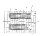
- FIG. 2 is an explanatory view illustrating the internal structure of the conveyor belt of FIG. 1 in plan view.
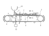
- FIG. 3 is an explanatory view illustrating the belt conveyor apparatus to which the conveyor belt of FIG. 4 is a cross-sectional view taken along the line AA in FIG.
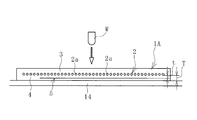
- FIG. 5 is an explanatory view illustrating the analysis model of the conveyor belt used in the loop coil embedding depth setting method of the present invention in a cross-sectional view.
- FIG. 6 is an explanatory view schematically illustrating a state in which the analysis model of FIG. 5 receives an impact from the upper cover rubber side.
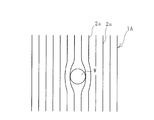
- FIG. 7 is an explanatory diagram schematically illustrating the analysis model of FIG.
- FIG. 6 is a plan view as viewed from the upper cover rubber side.
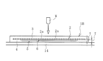
- FIG. 8 is a cross-sectional view illustrating another analysis model.
- FIG. 9 is an explanatory diagram illustrating the internal structure of the analysis model of FIG. 8 in plan view.
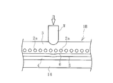
- FIG. 10 is an explanatory view schematically illustrating a state in which the analysis model of FIG. 8 receives an impact from the upper cover rubber side in a cross-sectional view.
- FIG. 11 is an explanatory view schematically illustrating the analysis model of FIG. 10 in a plan view as viewed from the upper cover rubber side.
- FIG. 12 is an explanatory view illustrating the state in which the molded body is vulcanized in a cross-sectional view.
- a method for setting the embedding depth of the loop coil in the conveyor belt of the present invention (hereinafter referred to as a setting method) and a method for manufacturing the conveyor belt will be described based on the embodiments shown in the drawings.
- a conveyor belt 1 manufactured by the method of manufacturing a conveyor belt according to the present invention illustrated in FIGS. 1 and 2 includes a core body layer 2, an upper cover rubber 3 disposed with the core body layer 2 sandwiched therebetween, and a lower cover.
- the rubber 4 is provided, and these are integrated through a vulcanization process.
- the conveyor belt 1 is configured by appropriately adding other components such as ear rubbers disposed at both ends in the belt width direction.
- the core body layer 2 includes a plurality of metal cords 2a (for example, steel cords) extending in the belt longitudinal direction and arranged in parallel in the belt width direction. More specifically, the core body layer 2 is covered with a cushion rubber, and the cushion rubber, the upper cover rubber 3 and the lower cover rubber 4 are joined by vulcanization adhesion.
- the metal cord 2a is indicated by a one-dot chain line at the center position.
- the upper cover rubber 3 and the lower cover rubber 4 for example, a rubber composition made of a diene rubber containing at least natural rubber and having good wear resistance with carbon black or the like is used.
- the layer thicknesses of the upper cover rubber 3 and the lower cover rubber 4 are appropriately determined depending on the performance required for the conveyor belt 1, but are determined in the range of, for example, 5 mm to 30 mm.
- Cushion rubber is rubber having excellent adhesion.
- a plurality of loop coils 5 are embedded in the lower cover rubber 4 at intervals in the longitudinal direction of the belt.
- a conductive wire 5a is formed in an annular shape, and a known one can be used.
- the conductive wire 5a may have a specification that is not brazed even if it is braided.
- the loop coil 5 is not limited to a double square shape, and various shapes such as a circular shape and an elliptical shape can also be adopted.
- the embedded plane position of the loop coil 5 is a region including the central portion in the belt width direction.
- the 3 includes a conveyor belt 1, a magnetic field generator 10, and a sensor 11.
- the belt conveyor device 7 illustrated in FIG. The conveyor belt 1 is stretched between the pulleys 8 and 8, and the conveyed product C is put into the upper cover rubber 3 through the chute portion 13. As illustrated in FIG. 4, the conveyor belt 1 is held in a trough shape that protrudes downward by the support roller 9 on the carrier side, so that the loaded conveyed product C is mainly placed at the center in the belt width direction. .
- the magnetic field generator 10 is disposed adjacent to the lower cover rubber 4. For each loop coil 5 that passes in the vicinity of the magnetic field generation unit 10, the magnetic field generation unit 10 transmits an electromagnetic wave, for example. A dielectric current is induced in each loop coil 5 by this electromagnetic wave. If the loop coil 5 is disconnected, no induced current is induced.
- Sensor 11 is arranged adjacent to lower cover rubber 4.
- the sensor 11 is disposed slightly downstream in the traveling direction of the conveyor belt 1 with respect to the magnetic field generator 10. For each loop coil 5 passing in the vicinity of the sensor 11, the sensor 11 detects whether or not an induced current is generated. Data detected by the sensor 11 is transmitted to the control unit 12. Based on the data detected by the sensor 11, the control unit 12 determines that the conveyor belt 1 has not been longitudinally split if an induced current is generated. If the induced current is not generated, the control unit 12 longitudinally splits the conveyor belt 1. Is determined to have occurred. When it is judged that the conveyor belt 1 has a longitudinal tear, the operation of the conveyor belt 1 is stopped and a warning or the like is issued.
- the conveyor belt 1 is subject to impacts and external forces due to the conveyed product C put into the upper cover rubber 3, and the loop coil 5 may be damaged due to these. Therefore, in the setting method of the present invention, an appropriate embedding position is set in which the loop coil 5 is not easily damaged even when these act. Specifically, an appropriate vertical distance (rubber thickness t) between the core layer 2 and the loop coil 5 shown in FIG. 1 is set. This rubber thickness t is the vertical distance between the lower surface of the core layer 2 and the upper surface of the loop coil 5.
- the setting method of the present invention uses a two-dimensional or three-dimensional FEM analysis model 1 ⁇ / b> A of an actual conveyor belt 1.
- the analysis model 1A includes the same components as the actual conveyor belt 1. In the drawing, the same reference numerals as those of the actual conveyor belt 1 are given to the respective components of the analysis model 1A.
- material property values Young's modulus, Poisson's ratio, etc.
- the vertical stress and deformation generated in the loop coil 5 are calculated by FEM analysis.
- the specification and fall height of the fallen object W are appropriately determined based on the actual use conditions of the conveyor belt 1 (the shape and weight of the transported object C) and the like.
- the analysis model 1A is in a condition of being horizontally placed on a flat rigid body 14 such as a steel plate.
- the analysis model 1A can be set to a condition in which the analysis model 1A is supported by the support roller 9 with a gap in the longitudinal direction of the belt as in the actual belt conveyor device 7, but the entire analysis model 1A is placed on the rigid body 14. By doing so, since it becomes a severe condition which is easy to damage the loop coil 5, it is possible to set a more appropriate embedment depth position.
- the upper cover rubber 3 and the loop coil 5 are locally distorted and deformed in a range corresponding to the fall point of the fallen object W.
- the metal cord 2a is displaced in the belt width direction.
- the maximum stress and the maximum deformation amount generated in the loop coil 5 at this time are calculated.
- This analysis is performed by changing the embedded depth position (rubber thickness t) of the loop coil 5.
- the relationship between each embedding depth position and the maximum stress or maximum deformation amount is grasped, the range where the maximum stress or the maximum deformation amount is minimized is grasped, and this range is determined by the actual conveyor belt 1.
- the loop coil 5 is set to an appropriate embedment depth position.
- the parallel metal cords 2a are joined by a cushion rubber interposed between the gaps. Is elastically deformed. Therefore, since the force that restrains the displacement of the metal cord 2a in the belt width direction is weak, the metal cord 2a is locally displaced in the belt width direction, and the distance between the metal cords 2a in the belt width direction is widened.
- the displacement amount of the metal cord 2a in the belt width direction correlates with the maximum stress and the maximum deformation amount generated in the loop coil 5.
- an appropriate embedment depth position of the loop coil 5 can be set.
- an appropriate embedment depth of the loop coil 5 is obtained by using the amount of displacement of the metal cord 2a in the belt width direction as the amount of change corresponding to at least one of the main stress or deformation amount generated in the loop coil 5 in this way. The position may be set.
- an appropriate embedding depth that can improve the durability of the loop coil 5 in the actual conveyor belt 1 is set without manufacturing and testing many samples. It becomes possible. In the development stage of the conveyor belt 1, it is very useful because an appropriate embedment depth position of the loop coil 5 can be grasped according to the specifications of the conveyor belt 1 (rubber type, metal cord type, etc.).
- the analysis model 1A may be three-dimensional or two-dimensional, but by making it two-dimensional, the time required for model production can be significantly reduced. If the correlation between the displacement of the metal cord 2a in the belt width direction and the maximum stress or maximum deformation generated in the loop coil 5 can be sufficiently grasped, the appropriate embedment depth position of the loop coil 5 can be determined by the two-dimensional analysis model 1. Can be set with high accuracy.
- FIGS. 8 and 9 Another analysis model 1B illustrated in FIGS. 8 and 9 can also be used.
- a protective layer 6 is embedded in the lower cover rubber 4 at a predetermined depth between the upper and lower sides of the core layer 2 and the loop coil 5 with respect to the analysis model 1A described above. That is, the protective layer 6 is embedded in the lower cover rubber 4 with an interval in the belt longitudinal direction.
- the protective layer 6 has a specification in which the elongation is smaller (modulus is larger) than the rubber used in the conveyor belt 1 under the same conditions.
- a protective layer 6 having a thickness of 0.2 mm to 3.0 mm is used.
- the protective layer 6 is disposed so as to cover the entire range of the corresponding loop coil 5 (the loop coil 5 arranged closest to the protective layer 6) in a plan view as viewed from the upper cover rubber 3 side.
- the metal cord 2 a is indicated by a one-dot chain line at the center position, and illustration is omitted in a range corresponding to the protective layer 6.
- the lower protective layer 6 is partially cut away.
- the protective layer 6 can be formed of various materials such as natural fiber, resin, metal and the like.
- the structure of the protective layer 6 can employ various structures such as a woven structure and a film shape. Examples of the woven structure include a plain woven structure, a weave woven structure, a twill woven structure, and a satin woven structure.
- the protective layer 6 is formed of a plurality of wires 6a.
- a desired wire 6a such as natural fiber, resin fiber, or metal fiber can be used. Since the protective layer 6 has a plain weave structure, a plurality of wires 6a extending in the belt width direction are arranged in parallel in the belt longitudinal direction. Therefore, the wire 6a extending in the belt width direction is in a state of intersecting with the metal cord 2a arranged in parallel in the belt width direction.
- the upper cover rubber 3 and the loop coil 5 are locally distorted and slightly deformed in a range corresponding to the fall point of the fallen object W, but the metal cord 2a hardly displaces in the belt width direction.
- the maximum stress and the maximum deformation amount generated in the loop coil 5 at this time are calculated. This analysis is performed by changing the embedded depth position (rubber thickness t) of the loop coil 5. As a result, the relationship between each embedding depth position and the maximum stress or maximum deformation amount is grasped, the range where the maximum stress or the maximum deformation amount is minimized is grasped, and this range is determined by the actual conveyor belt 1.
- the loop coil 5 is set to an appropriate embedment depth position.
- the protective layer 6 since the protective layers 6 are arranged so as to cover the metal cords 2a arranged in parallel, the protective layer 6 functions to bind and restrain the metal cords 2a adjacent in the belt width direction. is doing. Therefore, as shown in FIGS. 10 and 11, when an impact or external force is applied to the analysis model 1B, the displacement of the metal cord 2a in the belt width direction is suppressed as compared to the previous analysis model 1A.
- the conveyor belt 1 is manufactured by placing the molded body 1C in the molds 15 and vulcanizing the molded body 1C.
- the loop coil 5 is embedded at an appropriate embedding position set using the analysis model 1B, and a predetermined depth between the upper and lower sides of the core layer 2 and the loop coil 5 is embedded.
- the molded body 1C of the unvulcanized conveyor belt in which the protective layer 6 is embedded in the lower cover rubber 4 is formed.
- the conveyor belt 1 is manufactured by placing the molded body 1C in the molds 15 and vulcanizing the molded body 1C.
- the conveyor belt 1 manufactured in this way has a loop coil 5 embedded in an appropriate embedment position set using the analysis models 1A and 1B. Therefore, it becomes easy to prevent the loop coil 5 from being damaged due to an impact or an external force caused by the conveyed product C thrown into the upper cover rubber 3. Accordingly, it is advantageous to avoid the misconception that the loop coil 5 is damaged even if the conveyor belt 1 is not longitudinally split.
- the protective layer 6 when the protective layer 6 is provided as in the above analysis model 1B, the belt width direction of the metal cord 2a even if a local impact or external force is applied by the conveyed object C or the like. The displacement to is suppressed. Along with this, the acting impact and external force are widely dispersed in the metal cord 2a.
- the protective layer 6 also absorbs and relaxes impacts and external forces. Therefore, even if a large impact or external force is locally applied to the conveyor belt 1, the loop coil 5 is hardly damaged, and the durability is further improved. Therefore, it is more advantageous to avoid the situation that the loop coil 5 is damaged even if the conveyor belt 1 is not longitudinally split, and the occurrence of the longitudinal tear of the conveyor belt 1 is more accurately detected. Is possible.
- each protective layer 6 is embedded in the lower cover rubber 4 with an interval in the belt longitudinal direction, an increase in the weight of the conveyor belt 1 due to the provision of the protective layer 6 can be suppressed. Deterioration of flexibility can also be avoided. Since these have a great influence on reducing the energy required for operating the conveyor belt 1, they contribute to energy saving.
- the protective layer was set to a plain weave structure made of nylon fibers. However, it was found that in the analysis model 1B, the main stress and deformation amount generated in the loop coil 5 are about 60% in the analysis model 1A.
Landscapes
- Engineering & Computer Science (AREA)
- Mechanical Engineering (AREA)
- Belt Conveyors (AREA)
- Control Of Conveyors (AREA)
Abstract
Procédé de réglage de la profondeur d'incorporation d'une bobine en boucle, moyennant quoi une profondeur d'incorporation dans une bande transporteuse à laquelle la durabilité d'une bobine en boucle peut être améliorée peut être réglée sans test à l'aide de nombreux échantillons, et procédé de fabrication d'une bande transporteuse dans laquelle la bobine en boucle est incorporée. Selon la présente invention, un modèle d'analyse FEM bidimensionnel ou tridimensionnel 1A d'une bande transporteuse réelle 1 est créé, et la profondeur d'incorporation appropriée d'une bobine en boucle 6 dans la bande transporteuse réelle 1, c'est-à-dire l'épaisseur de caoutchouc t entre une couche centrale 2 et une bobine en boucle 5, est réglée sur la base de la quantité de déformation et/ou de la contrainte principale qui se produit dans la bobine en boucle 5 dans le modèle d'analyse 1A lorsqu'un objet tombant W ayant des spécifications prédéfinies est lâché d'au-dessus d'un caoutchouc de revêtement supérieur 3 dans le modèle d'analyse 1A sur le caoutchouc de revêtement supérieur 3.
Priority Applications (3)
| Application Number | Priority Date | Filing Date | Title |
|---|---|---|---|
| US16/463,343 US10569488B2 (en) | 2016-11-24 | 2017-10-05 | Method for setting loop coil embedding depth in conveyor belt, and method for manufacturing conveyor belt |
| CN201780065587.6A CN109996744B (zh) | 2016-11-24 | 2017-10-05 | 传送带中的环状线圈的埋设深度的设定方法以及传送带的制造方法 |
| DE112017005938.0T DE112017005938B4 (de) | 2016-11-24 | 2017-10-05 | Verfahren zum festlegen der einbettungstiefe von schleifenspulen in einem förderband und verfahren zum herstellen eines förderbandes |
Applications Claiming Priority (2)
| Application Number | Priority Date | Filing Date | Title |
|---|---|---|---|
| JP2016-228085 | 2016-11-24 | ||
| JP2016228085A JP6819242B2 (ja) | 2016-11-24 | 2016-11-24 | コンベヤベルトでのループコイルの埋設深さの設定方法およびコンベヤベルトの製造方法 |
Publications (1)
| Publication Number | Publication Date |
|---|---|
| WO2018096800A1 true WO2018096800A1 (fr) | 2018-05-31 |
Family
ID=62195057
Family Applications (1)
| Application Number | Title | Priority Date | Filing Date |
|---|---|---|---|
| PCT/JP2017/036285 Ceased WO2018096800A1 (fr) | 2016-11-24 | 2017-10-05 | Procédé de réglage de profondeur d'incorporation de bobine en boucle dans une bande transporteuse, et procédé de fabrication de bande transporteuse |
Country Status (5)
| Country | Link |
|---|---|
| US (1) | US10569488B2 (fr) |
| JP (1) | JP6819242B2 (fr) |
| CN (1) | CN109996744B (fr) |
| DE (1) | DE112017005938B4 (fr) |
| WO (1) | WO2018096800A1 (fr) |
Families Citing this family (1)
| Publication number | Priority date | Publication date | Assignee | Title |
|---|---|---|---|---|
| JP7564426B2 (ja) * | 2020-07-02 | 2024-10-09 | 横浜ゴム株式会社 | コンベヤベルトの縦裂き検出装置および方法 |
Citations (4)
| Publication number | Priority date | Publication date | Assignee | Title |
|---|---|---|---|---|
| JP2002228525A (ja) * | 2001-01-31 | 2002-08-14 | Bando Chem Ind Ltd | 搬送物からの衝撃を入力条件とする応力解析方法 |
| JP2005075617A (ja) * | 2003-09-03 | 2005-03-24 | Yokohama Rubber Co Ltd:The | コンベヤベルトのシミュレーション方法 |
| US20130081929A1 (en) * | 2011-09-30 | 2013-04-04 | Veyance Technologies, Inc. | Superelastic low rolling resistance conveyor belt |
| JP2016185879A (ja) * | 2015-03-27 | 2016-10-27 | バンドー化学株式会社 | スチールコードコンベヤベルトの縦裂検出装置及びスチールコードコンベヤベルトの縦裂検出システム |
Family Cites Families (8)
| Publication number | Priority date | Publication date | Assignee | Title |
|---|---|---|---|---|
| DE3347570A1 (de) * | 1983-12-30 | 1985-07-11 | Conrad Scholtz Ag, 2000 Hamburg | Foerdergurt mit eingebetteten leiterschleifen und verfahren zu seiner herstellung |
| JP2014028682A (ja) * | 2012-07-31 | 2014-02-13 | Bridgestone Corp | コンベヤベルトおよびコンベヤベルト装置 |
| JP2014031241A (ja) | 2012-08-02 | 2014-02-20 | Bridgestone Corp | コンベヤベルトおよびコンベヤベルト装置 |
| JP5915456B2 (ja) * | 2012-08-23 | 2016-05-11 | 横浜ゴム株式会社 | コンベヤベルト |
| JP2015071493A (ja) | 2013-10-04 | 2015-04-16 | 株式会社ブリヂストン | コンベヤベルトおよびコンベヤベルト用環状導電体 |
| JP6668616B2 (ja) * | 2015-06-03 | 2020-03-18 | 横浜ゴム株式会社 | コンベヤベルト |
| JP6790339B2 (ja) * | 2015-08-24 | 2020-11-25 | 横浜ゴム株式会社 | コンベヤベルトのモニタリングシステム |
| JP6743472B2 (ja) * | 2016-04-22 | 2020-08-19 | 横浜ゴム株式会社 | 衝撃試験方法および装置 |
-
2016
- 2016-11-24 JP JP2016228085A patent/JP6819242B2/ja active Active
-
2017
- 2017-10-05 WO PCT/JP2017/036285 patent/WO2018096800A1/fr not_active Ceased
- 2017-10-05 CN CN201780065587.6A patent/CN109996744B/zh active Active
- 2017-10-05 DE DE112017005938.0T patent/DE112017005938B4/de active Active
- 2017-10-05 US US16/463,343 patent/US10569488B2/en not_active Expired - Fee Related
Patent Citations (4)
| Publication number | Priority date | Publication date | Assignee | Title |
|---|---|---|---|---|
| JP2002228525A (ja) * | 2001-01-31 | 2002-08-14 | Bando Chem Ind Ltd | 搬送物からの衝撃を入力条件とする応力解析方法 |
| JP2005075617A (ja) * | 2003-09-03 | 2005-03-24 | Yokohama Rubber Co Ltd:The | コンベヤベルトのシミュレーション方法 |
| US20130081929A1 (en) * | 2011-09-30 | 2013-04-04 | Veyance Technologies, Inc. | Superelastic low rolling resistance conveyor belt |
| JP2016185879A (ja) * | 2015-03-27 | 2016-10-27 | バンドー化学株式会社 | スチールコードコンベヤベルトの縦裂検出装置及びスチールコードコンベヤベルトの縦裂検出システム |
Also Published As
| Publication number | Publication date |
|---|---|
| US10569488B2 (en) | 2020-02-25 |
| DE112017005938B4 (de) | 2021-05-27 |
| US20190351633A1 (en) | 2019-11-21 |
| CN109996744B (zh) | 2020-03-03 |
| DE112017005938T5 (de) | 2019-08-08 |
| CN109996744A (zh) | 2019-07-09 |
| JP6819242B2 (ja) | 2021-01-27 |
| JP2018083693A (ja) | 2018-05-31 |
Similar Documents
| Publication | Publication Date | Title |
|---|---|---|
| US4621727A (en) | Conveyor belt damage sensor | |
| CA2684828C (fr) | Detecteur de dechirure de bande transporteuse | |
| JP6450164B2 (ja) | マイクロワイヤセンサを備えるコンベヤベルトの裂け目検出システム | |
| JP6353321B2 (ja) | ゴム・コード複合体の機械的特性の評価方法 | |
| AU2013297827B2 (en) | Conveyor belt and conveyor belt apparatus | |
| WO2018096801A1 (fr) | Bande transporteuse et dispositif de transport à bande | |
| WO2018096800A1 (fr) | Procédé de réglage de profondeur d'incorporation de bobine en boucle dans une bande transporteuse, et procédé de fabrication de bande transporteuse | |
| Hansen et al. | Fatigue response of a host structure with interlaced embedded devices | |
| JP2010190578A (ja) | リンクチェーンの伸びの測定方法および装置 | |
| US10712234B2 (en) | Belt and pulley systems and methods of detecting belt damage | |
| JP2015071493A (ja) | コンベヤベルトおよびコンベヤベルト用環状導電体 | |
| CN107614400B (zh) | 传送带 | |
| US11378158B2 (en) | Method for producing a belt- or band-shaped component having an electronic device | |
| JP5756287B2 (ja) | トレッド溝の耐溝底クラック性能の評価方法 | |
| EP4428017A2 (fr) | Renforcement de trajectoire de roue de chenille en caoutchouc | |
| KR20090127404A (ko) | 칩 분할 무단 벨트 | |
| JP6822079B2 (ja) | 耐カット性能の評価のための試験装置 | |
| JP2015202931A (ja) | ゴムベルト | |
| CA3055651C (fr) | Bande transporteuse avec pile de renfort | |
| JP2009222469A (ja) | コンベヤベルト及びコンベヤベルトの製造方法 | |
| JP2022142940A (ja) | 内部残留ひずみを測定する方法およびそのひずみを測定するためのセンサ | |
| Williams et al. | Fatigue Characterization of 3D Printed Elastomer Material | |
| JP2016199368A (ja) | コンベヤベルト及びコンベヤベルト装置 | |
| CZ2008171A3 (cs) | Zpusob vytvorení preplátovaného spoje pásu pásového dopravníku a spoj pásu vytvorený tímto zpusobem | |
| JP2007203982A (ja) | タイヤ構成用ゴムシートおよび同ゴムシートを用いたタイヤ |
Legal Events
| Date | Code | Title | Description |
|---|---|---|---|
| 121 | Ep: the epo has been informed by wipo that ep was designated in this application |
Ref document number: 17875054 Country of ref document: EP Kind code of ref document: A1 |
|
| 122 | Ep: pct application non-entry in european phase |
Ref document number: 17875054 Country of ref document: EP Kind code of ref document: A1 |