WO2018096835A1 - Cellule et dispositif électronique - Google Patents
Cellule et dispositif électronique Download PDFInfo
- Publication number
- WO2018096835A1 WO2018096835A1 PCT/JP2017/037394 JP2017037394W WO2018096835A1 WO 2018096835 A1 WO2018096835 A1 WO 2018096835A1 JP 2017037394 W JP2017037394 W JP 2017037394W WO 2018096835 A1 WO2018096835 A1 WO 2018096835A1
- Authority
- WO
- WIPO (PCT)
- Prior art keywords
- battery
- carbon fiber
- negative electrode
- positive electrode
- fiber sheet
- Prior art date
- Legal status (The legal status is an assumption and is not a legal conclusion. Google has not performed a legal analysis and makes no representation as to the accuracy of the status listed.)
- Ceased
Links
Images

Classifications
-
- H—ELECTRICITY
- H01—ELECTRIC ELEMENTS
- H01M—PROCESSES OR MEANS, e.g. BATTERIES, FOR THE DIRECT CONVERSION OF CHEMICAL ENERGY INTO ELECTRICAL ENERGY
- H01M4/00—Electrodes
- H01M4/02—Electrodes composed of, or comprising, active material
- H01M4/64—Carriers or collectors
- H01M4/66—Selection of materials
- H01M4/663—Selection of materials containing carbon or carbonaceous materials as conductive part, e.g. graphite, carbon fibres
-
- H—ELECTRICITY
- H01—ELECTRIC ELEMENTS
- H01M—PROCESSES OR MEANS, e.g. BATTERIES, FOR THE DIRECT CONVERSION OF CHEMICAL ENERGY INTO ELECTRICAL ENERGY
- H01M10/00—Secondary cells; Manufacture thereof
- H01M10/05—Accumulators with non-aqueous electrolyte
- H01M10/058—Construction or manufacture
- H01M10/0585—Construction or manufacture of accumulators having only flat construction elements, i.e. flat positive electrodes, flat negative electrodes and flat separators
-
- H—ELECTRICITY
- H01—ELECTRIC ELEMENTS
- H01M—PROCESSES OR MEANS, e.g. BATTERIES, FOR THE DIRECT CONVERSION OF CHEMICAL ENERGY INTO ELECTRICAL ENERGY
- H01M10/00—Secondary cells; Manufacture thereof
- H01M10/04—Construction or manufacture in general
-
- H—ELECTRICITY
- H01—ELECTRIC ELEMENTS
- H01M—PROCESSES OR MEANS, e.g. BATTERIES, FOR THE DIRECT CONVERSION OF CHEMICAL ENERGY INTO ELECTRICAL ENERGY
- H01M10/00—Secondary cells; Manufacture thereof
- H01M10/05—Accumulators with non-aqueous electrolyte
- H01M10/058—Construction or manufacture
- H01M10/0587—Construction or manufacture of accumulators having only wound construction elements, i.e. wound positive electrodes, wound negative electrodes and wound separators
-
- H—ELECTRICITY
- H01—ELECTRIC ELEMENTS
- H01M—PROCESSES OR MEANS, e.g. BATTERIES, FOR THE DIRECT CONVERSION OF CHEMICAL ENERGY INTO ELECTRICAL ENERGY
- H01M50/00—Constructional details or processes of manufacture of the non-active parts of electrochemical cells other than fuel cells, e.g. hybrid cells
- H01M50/10—Primary casings; Jackets or wrappings
- H01M50/116—Primary casings; Jackets or wrappings characterised by the material
- H01M50/124—Primary casings; Jackets or wrappings characterised by the material having a layered structure
-
- H—ELECTRICITY
- H01—ELECTRIC ELEMENTS
- H01M—PROCESSES OR MEANS, e.g. BATTERIES, FOR THE DIRECT CONVERSION OF CHEMICAL ENERGY INTO ELECTRICAL ENERGY
- H01M50/00—Constructional details or processes of manufacture of the non-active parts of electrochemical cells other than fuel cells, e.g. hybrid cells
- H01M50/40—Separators; Membranes; Diaphragms; Spacing elements inside cells
- H01M50/471—Spacing elements inside cells other than separators, membranes or diaphragms; Manufacturing processes thereof
- H01M50/474—Spacing elements inside cells other than separators, membranes or diaphragms; Manufacturing processes thereof characterised by their position inside the cells
-
- H—ELECTRICITY
- H01—ELECTRIC ELEMENTS
- H01M—PROCESSES OR MEANS, e.g. BATTERIES, FOR THE DIRECT CONVERSION OF CHEMICAL ENERGY INTO ELECTRICAL ENERGY
- H01M50/00—Constructional details or processes of manufacture of the non-active parts of electrochemical cells other than fuel cells, e.g. hybrid cells
- H01M50/40—Separators; Membranes; Diaphragms; Spacing elements inside cells
- H01M50/471—Spacing elements inside cells other than separators, membranes or diaphragms; Manufacturing processes thereof
- H01M50/477—Spacing elements inside cells other than separators, membranes or diaphragms; Manufacturing processes thereof characterised by their shape
-
- H—ELECTRICITY
- H01—ELECTRIC ELEMENTS
- H01M—PROCESSES OR MEANS, e.g. BATTERIES, FOR THE DIRECT CONVERSION OF CHEMICAL ENERGY INTO ELECTRICAL ENERGY
- H01M50/00—Constructional details or processes of manufacture of the non-active parts of electrochemical cells other than fuel cells, e.g. hybrid cells
- H01M50/40—Separators; Membranes; Diaphragms; Spacing elements inside cells
- H01M50/471—Spacing elements inside cells other than separators, membranes or diaphragms; Manufacturing processes thereof
- H01M50/48—Spacing elements inside cells other than separators, membranes or diaphragms; Manufacturing processes thereof characterised by the material
- H01M50/483—Inorganic material
-
- H—ELECTRICITY
- H01—ELECTRIC ELEMENTS
- H01M—PROCESSES OR MEANS, e.g. BATTERIES, FOR THE DIRECT CONVERSION OF CHEMICAL ENERGY INTO ELECTRICAL ENERGY
- H01M50/00—Constructional details or processes of manufacture of the non-active parts of electrochemical cells other than fuel cells, e.g. hybrid cells
- H01M50/40—Separators; Membranes; Diaphragms; Spacing elements inside cells
- H01M50/489—Separators, membranes, diaphragms or spacing elements inside the cells, characterised by their physical properties, e.g. swelling degree, hydrophilicity or shut down properties
-
- H—ELECTRICITY
- H01—ELECTRIC ELEMENTS
- H01M—PROCESSES OR MEANS, e.g. BATTERIES, FOR THE DIRECT CONVERSION OF CHEMICAL ENERGY INTO ELECTRICAL ENERGY
- H01M50/00—Constructional details or processes of manufacture of the non-active parts of electrochemical cells other than fuel cells, e.g. hybrid cells
- H01M50/10—Primary casings; Jackets or wrappings
- H01M50/102—Primary casings; Jackets or wrappings characterised by their shape or physical structure
- H01M50/105—Pouches or flexible bags
-
- H—ELECTRICITY
- H01—ELECTRIC ELEMENTS
- H01M—PROCESSES OR MEANS, e.g. BATTERIES, FOR THE DIRECT CONVERSION OF CHEMICAL ENERGY INTO ELECTRICAL ENERGY
- H01M50/00—Constructional details or processes of manufacture of the non-active parts of electrochemical cells other than fuel cells, e.g. hybrid cells
- H01M50/10—Primary casings; Jackets or wrappings
- H01M50/116—Primary casings; Jackets or wrappings characterised by the material
- H01M50/117—Inorganic material
- H01M50/119—Metals
-
- H—ELECTRICITY
- H01—ELECTRIC ELEMENTS
- H01M—PROCESSES OR MEANS, e.g. BATTERIES, FOR THE DIRECT CONVERSION OF CHEMICAL ENERGY INTO ELECTRICAL ENERGY
- H01M50/00—Constructional details or processes of manufacture of the non-active parts of electrochemical cells other than fuel cells, e.g. hybrid cells
- H01M50/10—Primary casings; Jackets or wrappings
- H01M50/116—Primary casings; Jackets or wrappings characterised by the material
- H01M50/121—Organic material
-
- H—ELECTRICITY
- H01—ELECTRIC ELEMENTS
- H01M—PROCESSES OR MEANS, e.g. BATTERIES, FOR THE DIRECT CONVERSION OF CHEMICAL ENERGY INTO ELECTRICAL ENERGY
- H01M50/00—Constructional details or processes of manufacture of the non-active parts of electrochemical cells other than fuel cells, e.g. hybrid cells
- H01M50/10—Primary casings; Jackets or wrappings
- H01M50/116—Primary casings; Jackets or wrappings characterised by the material
- H01M50/124—Primary casings; Jackets or wrappings characterised by the material having a layered structure
- H01M50/126—Primary casings; Jackets or wrappings characterised by the material having a layered structure comprising three or more layers
- H01M50/129—Primary casings; Jackets or wrappings characterised by the material having a layered structure comprising three or more layers with two or more layers of only organic material
-
- Y—GENERAL TAGGING OF NEW TECHNOLOGICAL DEVELOPMENTS; GENERAL TAGGING OF CROSS-SECTIONAL TECHNOLOGIES SPANNING OVER SEVERAL SECTIONS OF THE IPC; TECHNICAL SUBJECTS COVERED BY FORMER USPC CROSS-REFERENCE ART COLLECTIONS [XRACs] AND DIGESTS
- Y02—TECHNOLOGIES OR APPLICATIONS FOR MITIGATION OR ADAPTATION AGAINST CLIMATE CHANGE
- Y02E—REDUCTION OF GREENHOUSE GAS [GHG] EMISSIONS, RELATED TO ENERGY GENERATION, TRANSMISSION OR DISTRIBUTION
- Y02E60/00—Enabling technologies; Technologies with a potential or indirect contribution to GHG emissions mitigation
- Y02E60/10—Energy storage using batteries
-
- Y—GENERAL TAGGING OF NEW TECHNOLOGICAL DEVELOPMENTS; GENERAL TAGGING OF CROSS-SECTIONAL TECHNOLOGIES SPANNING OVER SEVERAL SECTIONS OF THE IPC; TECHNICAL SUBJECTS COVERED BY FORMER USPC CROSS-REFERENCE ART COLLECTIONS [XRACs] AND DIGESTS
- Y02—TECHNOLOGIES OR APPLICATIONS FOR MITIGATION OR ADAPTATION AGAINST CLIMATE CHANGE
- Y02P—CLIMATE CHANGE MITIGATION TECHNOLOGIES IN THE PRODUCTION OR PROCESSING OF GOODS
- Y02P70/00—Climate change mitigation technologies in the production process for final industrial or consumer products
- Y02P70/50—Manufacturing or production processes characterised by the final manufactured product
Definitions
- This technology relates to batteries and electronic devices.
- the secondary battery In general, in the field of secondary batteries, by improving the impact resistance, the secondary battery is deformed due to the impact and the positive and negative electrodes are short-circuited, preventing the secondary battery from generating heat. It is hoped to do.
- an object of the present technology is to provide a battery and an electronic device that improve impact resistance and ensure high stability against external force.
- the present technology for example, A battery element; A film exterior material that houses the battery element; A battery comprising a carbon fiber sheet provided between a battery element and a film sheathing material and containing long fibers.
- the present technology may be an electronic device having this battery.
- the impact resistance of the battery can be improved without increasing the weight of the battery as much as possible.
- the effect described here is not necessarily limited, and may be any effect described in the present technology. Further, the contents of the present technology are not construed as being limited by the exemplified effects.
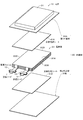
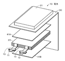
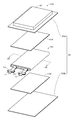
- FIG. 1 is an exploded perspective view of a battery according to an embodiment.
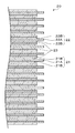
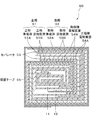
- FIG. 2 is a view for explaining the configuration of the electrode body according to the embodiment.
- FIG. 3A is a diagram for explaining a positive electrode current collector according to one embodiment
- FIG. 3B is a diagram for explaining a negative electrode current collector according to one embodiment.
- FIG. 4 is a diagram for explaining a modification.
- FIG. 5 is a diagram for explaining a modification.
- FIG. 6 is a diagram for explaining a modification.
- FIG. 7 is a diagram for explaining a modification.
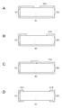
- 8A to 8D are diagrams for explaining a modification.
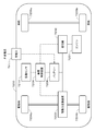
- FIG. 9 is a diagram for explaining an application example.
- FIG. 10 is a diagram for explaining an application example.
- FIG. 1 is an exploded perspective view showing a configuration example of a nonaqueous electrolyte secondary battery (hereinafter simply referred to as “battery”) 10 according to an embodiment of the present technology.
- a battery 10 according to an embodiment of the present technology is a so-called laminate film battery, and is a flat or square stacked electrode body (hereinafter referred to as an electrode body) that is an example of a battery element.
- 20) and carbon fiber sheets 41A and 41B are accommodated inside a film-shaped exterior member 30 and can be reduced in size, weight, and thickness.
- the positive electrode lead 11 and the negative electrode lead 12 are attached to the electrode body 20.
- the electrode body 20 has a main surface 20A that is substantially rectangular when viewed from above, and a main surface 20B opposite to the main surface 20A.
- the main surface 20A has a side part 20C in the longitudinal direction and a side part 20D in the short direction.
- Carbon fiber sheets 41 ⁇ / b> A and 41 ⁇ / b> B are provided between the exterior material 30 and the electrode body 20.
- the positive electrode lead 11 and the negative electrode lead 12 are led out in the same direction from one short side of the battery 10.
- the short side of the electrode body 20 from which the positive electrode lead 11 and the negative electrode lead 12 are derived is referred to as a top side
- the opposite short side is referred to as a bottom side
- the long side is referred to as the side side.
- the positive electrode lead 11 and the negative electrode lead 12 have, for example, a thin plate shape or a mesh shape.
- the positive electrode lead 11 and the negative electrode lead 12 are made of a metal material such as aluminum, copper, nickel, or stainless steel, for example.
- Adhesive films 13 for preventing intrusion of outside air are inserted between the exterior material 30 and the positive electrode lead 11 and between the exterior material 30 and the negative electrode lead 12, respectively.
- the adhesion film 13 is made of a material having adhesion to the positive electrode lead 11 and the negative electrode lead 12, for example, a polyolefin resin such as polyethylene, polypropylene, modified polyethylene, or modified polypropylene.
- the exterior material 30 is a laminate film having flexibility.
- the exterior material 30 includes first and second film-shaped exterior materials 30A and 30B having a rectangular shape.
- the first and second exterior materials 30A and 30B have the same size and are overlapped with the electrode body 20 interposed therebetween.
- the four sides of the first and second exterior materials 30A and 30B that are overlaid are fused to form a fused portion at the peripheral edge of the first and second exterior materials 30A and 30B.
- the first exterior member 30 ⁇ / b> A has a housing portion 31 for housing the electrode body 20. This accommodating part 31 is formed by deep drawing, for example.
- the exterior material 30 has, for example, a configuration in which a heat-sealing resin layer, a metal layer, and a surface protective layer are sequentially laminated.
- the surface on the side of the heat-sealing resin layer is the surface on the side where the electrode body 20 is accommodated.
- the material for the heat-sealing resin layer include polypropylene (PP) and polyethylene (PE).
- the material for the metal layer include aluminum.
- Examples of the material for the surface protective layer include nylon (Ny).
- the exterior member 30 is made of a rectangular aluminum laminated film in which, for example, a nylon film, an aluminum foil, and a polyethylene film are bonded together in this order.
- the packaging material 30 is disposed, for example, so that the heat-sealing resin layer side and the electrode body 20 face each other, and the outer edge portions are in close contact with each other by fusion or an adhesive.
- the exterior material 30 may be made of a laminated film having another structure, a polymer film such as polypropylene, or a metal film instead of the above-described laminated film.
- a laminate film in which an aluminum film is used as a core and a polymer film is laminated on one or both sides thereof may be used.
- a coloring material is included in at least 1 layer chosen from the thing further provided with a colored layer and / or a heat-fusion resin layer and a surface protective layer.
- a thing may be used.
- the adhesive layer may include a coloring material.
- a carbon fiber sheet 41A is provided between the first exterior material 30A and the main surface 20A of the electrode body 20, and a carbon fiber sheet 41B is provided between the second exterior material 30B and the main surface 20B of the electrode body 20. It has been.
- the carbon fiber sheet 41A will be described unless otherwise specified, but the same applies to the carbon fiber sheet 41B.
- the carbon fiber sheet 41A is made of carbon fiber.
- a known carbon fiber such as polyacrylonitrile-based carbon fiber or pitch-based carbon fiber can be applied.
- the carbon fiber sheet in the present technology is a sheet containing long fibers.
- the long fiber is, for example, a carbon fiber having a length of 50% to 120% or more with respect to the length of the side portion 20D of the main surface 20A.
- the long fiber is a woven fabric or a non-woven fabric.
- a widely known method can be applied. It is also possible to impregnate a long fiber array with a resin as a binder to form a sheet. Further, for example, long fibers can be knitted into a sheet shape. In this case, there is no need to mix long fibers with plastic or the like, and a carbon fiber sheet containing no binder (not containing) can be obtained.
- the fiber diameter of the long fiber is, for example, 1 to 100 ⁇ m, and preferably 5 to 20 ⁇ m.
- a plurality of long fibers may constitute a fiber bundle (filament).
- a plurality of filaments may further form a bundle.
- the long fibers are arranged in at least two directions, more specifically, in two directions substantially orthogonal to each other. Thereby, the intensity
- the coverage of the carbon fiber sheets 41A and 41B with respect to the entire surface of the electrode body 20 is preferably 70% or more and 110% or less, for example.
- the average thickness of the carbon fiber sheet 41A is 20 ⁇ m or more and 200 ⁇ m or less, preferably 20 ⁇ m or more and 150 ⁇ m, from the viewpoint of securing the capacity of the battery.
- FIG. 2 shows an example of the configuration of the electrode body 20.
- the electrode body 20 includes a positive electrode 21, a negative electrode 22, a separator 23 provided between the positive electrode 21 and the negative electrode 22, an electrolyte layer 24A provided between the positive electrode 21 and the separator 23, a negative electrode 22 and a separator. And an electrolyte layer 24 ⁇ / b> B provided between the two.
- the positive electrode 21 has a structure in which a positive electrode active material layer 21B is provided on both surfaces of a positive electrode current collector 21A. Although not shown, the positive electrode active material layer 21B may be provided only on one surface of the positive electrode current collector 21A.
- the positive electrode current collector 21A includes a positive electrode active material layer forming part 21M and a positive electrode current collector exposed part 21N.
- the positive electrode active material layer forming part 21M When the positive electrode active material layer forming part 21M is viewed in a plan view from a direction perpendicular to the main surface of the positive electrode current collector 21A, the positive electrode active material layer forming part 21M has a rectangular shape.
- a positive electrode active material layer 21B is provided on both surfaces of the positive electrode active material layer forming portion 21M.
- the cathode current collector exposed portion 21N extends from a part of one side of the cathode active material layer forming portion 21M.
- the positive electrode current collector exposed portion 21N may be extended from the entire one side of the positive electrode active material layer forming portion 21M.
- the plurality of positive electrode current collector exposed portions 21 ⁇ / b> N are joined together, and the joined positive electrode current collector exposed portions 21 ⁇ / b> N are electrically connected to the positive electrode lead 11. Has been.
- the positive electrode current collector 21A is made of, for example, a metal foil such as an aluminum foil, a nickel foil, or a stainless steel foil.
- the positive electrode active material layer 21B includes, for example, a positive electrode active material that can occlude and release lithium as an electrode reactant.
- the positive electrode active material layer 21B may further contain an additive as necessary.
- the additive for example, at least one of a conductive agent and a binder can be used.
- lithium-containing compounds such as lithium oxide, lithium phosphorus oxide, lithium sulfide, or an intercalation compound containing lithium are suitable. Two or more kinds may be mixed and used.
- a lithium-containing compound containing lithium (Li), a transition metal element, and oxygen (O) is preferable. Examples of such a lithium-containing compound include a lithium composite oxide having a layered rock salt structure shown in Formula (A) and a lithium composite phosphate having an olivine structure shown in Formula (B). Can be mentioned.
- the lithium-containing compound includes at least one member selected from the group consisting of cobalt (Co), nickel (Ni), manganese (Mn), and iron (Fe) as a transition metal element.
- a lithium-containing compound include a lithium composite oxide having a layered rock salt type structure represented by the formula (C), formula (D), or formula (E), and a spinel type compound represented by the formula (F).
- LiNi 0.50 Co 0.20 Mn 0.30 O 2 Li a CoO 2 (A ⁇ 1), Li b NiO 2 (b ⁇ 1), Li c1 Ni c2 Co 1-c2 O 2 (c1 ⁇ 1, 0 ⁇ c2 ⁇ 1), Li d Mn 2 O 4 (d ⁇ 1) or Li e FePO 4 (e ⁇ 1).
- M1 represents at least one element selected from Groups 2 to 15 excluding nickel (Ni) and manganese (Mn).
- X represents a Group 16 element other than oxygen and 17) Represents at least one of the group elements, p, q, y, and z are 0 ⁇ p ⁇ 1.5, 0 ⁇ q ⁇ 1.0, 0 ⁇ r ⁇ 1.0, ⁇ 0.10 ⁇ y ⁇ 0.20 and 0 ⁇ z ⁇ 0.2.
- M2 represents at least one element selected from Group 2 to Group 15.
- a and b are 0 ⁇ a ⁇ 2.0 and 0.5 ⁇ b ⁇ 2.0. It is a value within the range.
- M3 is cobalt (Co), magnesium (Mg), aluminum (Al), boron (B), titanium (Ti), vanadium (V), chromium (Cr), iron (Fe ), Copper (Cu), zinc (Zn), zirconium (Zr), molybdenum (Mo), tin (Sn), calcium (Ca), strontium (Sr) and tungsten (W) F
- g, h, j and k are 0.8 ⁇ f ⁇ 1.2, 0 ⁇ g ⁇ 0.5, 0 ⁇ h ⁇ 0.5, g + h ⁇ 1, ⁇ 0.1 ⁇ j. ⁇ 0.2, 0 ⁇ k ⁇ 0.1
- the composition of lithium (Li) varies depending on the state of charge and discharge, and the value of f represents the value in the complete discharge state. )
- M4 is cobalt (Co), manganese (Mn), magnesium (Mg), aluminum (Al), boron (B), titanium (Ti), vanadium (V), chromium (Cr ), Iron (Fe), copper (Cu), zinc (Zn), molybdenum (Mo), tin (Sn), calcium (Ca), strontium (Sr), and tungsten (W).
- M, n, p and q are 0.8 ⁇ m ⁇ 1.2, 0.005 ⁇ n ⁇ 0.5, ⁇ 0.1 ⁇ p ⁇ 0.2, 0 ⁇ q ⁇ 0.1. (Note that the composition of lithium (Li) varies depending on the state of charge and discharge, and the value of m represents a value in a fully discharged state.)
- Li r Co (1-s) M5 s O (2-t) Fu (E) (However, in formula (E), M5 is nickel (Ni), manganese (Mn), magnesium (Mg), aluminum (Al), boron (B), titanium (Ti), vanadium (V), chromium (Cr ), Iron (Fe), copper (Cu), zinc (Zn), molybdenum (Mo), tin (Sn), calcium (Ca), strontium (Sr), and tungsten (W).
- R, s, t, and u are in a range of 0.8 ⁇ r ⁇ 1.2, 0 ⁇ s ⁇ 0.5, ⁇ 0.1 ⁇ t ⁇ 0.2, and 0 ⁇ u ⁇ 0.1. Note that the composition of lithium (Li) varies depending on the state of charge and discharge, and the value of r represents the value in the complete discharge state.)
- M6 is cobalt (Co), nickel (Ni), magnesium (Mg), aluminum (Al), boron (B), titanium (Ti), vanadium (V), chromium (Cr ), Iron (Fe), copper (Cu), zinc (Zn), molybdenum (Mo), tin (Sn), calcium (Ca), strontium (Sr), and tungsten (W).
- V, w, x, and y are in the range of 0.9 ⁇ v ⁇ 1.1, 0 ⁇ w ⁇ 0.6, 3.7 ⁇ x ⁇ 4.1, and 0 ⁇ y ⁇ 0.1. (Note that the composition of lithium (Li) varies depending on the state of charge and discharge, and the value of v represents the value in a fully discharged state.)
- Li z M7PO 4 (However, in formula (G), M7 is cobalt (Co), manganese (Mn), iron (Fe), nickel (Ni), magnesium (Mg), aluminum (Al), boron (B), titanium (Ti ), Vanadium (V), niobium (Nb), copper (Cu), zinc (Zn), molybdenum (Mo), calcium (Ca), strontium (Sr), tungsten (W) and zirconium (Zr) Z represents a value in a range of 0.9 ⁇ z ⁇ 1.1, wherein the composition of lithium (Li) varies depending on the state of charge and discharge, and the value of z is a complete discharge. Represents the value in the state.)
- lithium composite oxide containing Ni examples include lithium composite oxide (NCM), lithium (Li), lithium (Li), nickel (Ni), cobalt (Co), manganese (Mn), and oxygen (O).
- a lithium composite oxide (NCA) containing nickel (Ni), cobalt (Co), aluminum (Al), and oxygen (O) may be used.
- the lithium composite oxide containing Ni specifically, those shown in the following formula (H) or formula (I) may be used.
- Li v1 Ni w1 M1 ′ x1 O z1 (H) (In the formula, 0 ⁇ v1 ⁇ 2, w1 + x1 ⁇ 1, 0.2 ⁇ w1 ⁇ 1, 0 ⁇ x1 ⁇ 0.7, 0 ⁇ z ⁇ 3, and M1 ′ represents cobalt (Co), iron (Fe ), Manganese (Mn), copper (Cu), zinc (Zn), aluminum (Al), chromium (Cr), vanadium (Ba), titanium (Ti), magnesium (Mg), zirconium (Zr) and other transition metals (At least one element comprising :)
- Li v2 Ni w2 M2 ′ x2 O z2 (I) (Where 0 ⁇ v2 ⁇ 2, w2 + x2 ⁇ 1, 0.65 ⁇ w2 ⁇ 1, 0 ⁇ x2 ⁇ 0.35, 0 ⁇ z2 ⁇ 3, and M2 ′ represents cobalt (Co), iron (Fe ), Manganese (Mn), copper (Cu), zinc (Zn), aluminum (Al), chromium (Cr), vanadium (Ba), titanium (Ti), magnesium (Mg), zirconium (Zr) and other transition metals (At least one element comprising :)
- positive electrode materials capable of inserting and extracting lithium include inorganic compounds that do not contain lithium, such as MnO 2 , V 2 O 5 , V 6 O 13 , NiS, and MoS. It is done.
- the positive electrode material capable of inserting and extracting lithium (Li) may be other than the above.
- the positive electrode material illustrated above may be mixed 2 or more types by arbitrary combinations.
- binder examples include resin materials such as polyvinylidene fluoride (PVdF), polytetrafluoroethylene (PTFE), polyacrylonitrile (PAN), styrene butadiene rubber (SBR), and carboxymethyl cellulose (CMC), and these resin materials. At least one selected from copolymers and the like mainly composed of is used.
- PVdF polyvinylidene fluoride
- PTFE polytetrafluoroethylene
- PAN polyacrylonitrile
- SBR styrene butadiene rubber
- CMC carboxymethyl cellulose
- the conductive agent examples include carbon materials such as graphite, carbon black, and ketjen black, and one or more of them are used in combination.
- a metal material or a conductive polymer material may be used as long as it is a conductive material.
- the negative electrode 22 has a structure in which a negative electrode active material layer 22B is provided on both surfaces of a negative electrode current collector 22A, and the negative electrode active material layer 22B and the positive electrode active material layer 21B are arranged to face each other. Although not shown, the negative electrode active material layer 22B may be provided only on one surface of the negative electrode current collector 22A.
- the negative electrode current collector 22A includes a negative electrode active material layer forming part 22M and a negative electrode current collector exposed part 22N.
- the negative electrode active material layer forming part 22M When the negative electrode active material layer forming part 22M is viewed in a plan view from a direction perpendicular to the main surface of the negative electrode current collector 22A, the negative electrode active material layer forming part 22M has a rectangular shape.
- a negative electrode active material layer 22B is provided on both surfaces or one surface of the negative electrode active material layer forming portion 22M.
- the negative electrode current collector exposed portion 22N extends from a part of one side of the negative electrode active material layer forming portion 22M. 3B, the negative electrode current collector exposed portion 22N may be extended from the entire side of the negative electrode active material layer forming portion 22M.
- the negative electrode current collector 22A is made of, for example, a metal foil such as a copper foil, a nickel foil, or a stainless steel foil.
- the negative electrode active material layer 22B contains one or more negative electrode active materials capable of inserting and extracting lithium (Li).
- the negative electrode active material layer 22B may further contain additives such as a binder and a conductive agent as necessary.
- the electrochemical equivalent of the negative electrode 22 or the negative electrode active material is larger than the electrochemical equivalent of the positive electrode 21.
- lithium metal does not precipitate on the negative electrode 22 during charging. It is preferable.
- Examples of the negative electrode active material include carbon materials such as non-graphitizable carbon, graphitizable carbon, graphite, pyrolytic carbons, cokes, glassy carbons, organic polymer compound fired bodies, carbon fibers, and activated carbon. Is mentioned.
- examples of coke include pitch coke, needle coke, and petroleum coke.
- An organic polymer compound fired body refers to a carbonized material obtained by firing a polymer material such as phenol resin or furan resin at an appropriate temperature, and part of it is non-graphitizable carbon or graphitizable carbon.
- These carbon materials are preferable because the change in crystal structure that occurs during charge and discharge is very small, a high charge and discharge capacity can be obtained, and good cycle characteristics can be obtained.
- graphite is preferable because it has a high electrochemical equivalent and can provide a high energy density.
- non-graphitizable carbon is preferable because excellent cycle characteristics can be obtained.
- a battery having a low charge / discharge potential specifically, a battery having a charge / discharge potential close to that of lithium metal is preferable because a high energy density of the battery 10 can be easily realized.
- a material containing at least one of a metal element and a metalloid element as a constituent element for example, an alloy, a compound, or a mixture
- a high energy density can be obtained by using such a material.
- the use with a carbon material is more preferable because a high energy density can be obtained and excellent cycle characteristics can be obtained.
- the alloy includes an alloy including one or more metal elements and one or more metalloid elements in addition to an alloy composed of two or more metal elements.
- the nonmetallic element may be included.
- Examples of such a negative electrode active material include a metal element or a metalloid element capable of forming an alloy with lithium (Li).
- a metal element or a metalloid element capable of forming an alloy with lithium (Li).
- the negative electrode active material preferably includes a 4B group metal element or semimetal element in the short-period type periodic table as a constituent element, more preferably at least one of silicon (Si) and tin (Sn) as a constituent element. Is included. This is because silicon (Si) and tin (Sn) have a large ability to occlude and release lithium (Li), and a high energy density can be obtained.
- a negative electrode active material for example, a simple substance, an alloy or a compound of silicon (Si), a simple substance, an alloy or a compound of tin (Sn), or one or two or more phases thereof are at least partially included. The material which has is mentioned.
- Si As an alloy of silicon (Si), for example, as a second constituent element other than silicon (Si), tin (Sn), nickel (Ni), copper (Cu), iron (Fe), cobalt (Co), manganese (Mn), zinc (Zn), indium (In), silver (Ag), titanium (Ti), germanium (Ga), bismuth (Bi), antimony (Sb), and chromium (Cr).
- Si silicon
- Si tin
- Ni nickel
- Cu copper
- iron (Fe) cobalt
- Mn manganese
- Zn zinc
- indium (In) silver (Ag), titanium (Ti), germanium (Ga), bismuth (Bi), antimony (Sb), and chromium (Cr).
- Cr chromium
- tin (Sn) As an alloy of tin (Sn), for example, as a second constituent element other than tin (Sn), silicon (Si), nickel (Ni), copper (Cu), iron (Fe), cobalt (Co), manganese (Mn), zinc (Zn), indium (In), silver (Ag), titanium (Ti), germanium (Ga), bismuth (Bi), antimony (Sb), and chromium (Cr).
- Si silicon
- Ni nickel
- Cu copper
- iron (Fe) cobalt (Co)
- Mn manganese
- Zn zinc
- indium (In) silver (Ag), titanium (Ti), germanium (Ga), bismuth (Bi), antimony (Sb), and chromium (Cr).
- the thing containing 1 type is mentioned.
- tin (Sn) compound or silicon (Si) compound examples include those containing oxygen (O) or carbon (C).
- O oxygen
- C carbon
- the above-described compounds are used. Two constituent elements may be included.
- the Sn-based negative electrode active material includes cobalt (Co), tin (Sn), and carbon (C) as constituent elements, and the carbon content is 9.9 mass% or more and 29.7 mass%.
- the SnCoC-containing material is preferable, and the ratio of cobalt (Co) to the total of tin (Sn) and cobalt (Co) is 30% by mass or more and 70% by mass or less. This is because a high energy density can be obtained in such a composition range, and excellent cycle characteristics can be obtained.
- This SnCoC-containing material may further contain other constituent elements as necessary.
- other constituent elements include silicon (Si), iron (Fe), nickel (Ni), chromium (Cr), indium (In), niobium (Nb), germanium (Ge), titanium (Ti), and molybdenum.
- Mo silicon
- Al aluminum
- phosphorus (P) gallium
- Ga bismuth
- This SnCoC-containing material has a phase containing tin (Sn), cobalt (Co), and carbon (C), and this phase has a low crystallinity or an amorphous structure. It is preferable.
- this SnCoC-containing material it is preferable that at least a part of carbon (C) as a constituent element is bonded to a metal element or a metalloid element as another constituent element.
- the decrease in cycle characteristics is thought to be due to aggregation or crystallization of tin or the like, but such aggregation or crystallization can be suppressed by combining carbon (C) with other elements. Because.
- XPS X-ray photoelectron spectroscopy
- the peak of the carbon 1s orbital (C1s) appears at 284.5 eV in an energy calibrated apparatus so that the peak of the gold atom 4f orbital (Au4f) is obtained at 84.0 eV if it is graphite. .
- Au4f gold atom 4f orbital
- it will appear at 284.8 eV.
- the charge density of the carbon element increases, for example, when carbon is bonded to a metal element or a metalloid element, the C1s peak appears in a region lower than 284.5 eV.
- the peak of the synthetic wave of C1s obtained for the SnCoC-containing material appears in a region lower than 284.5 eV
- at least a part of the carbon contained in the SnCoC-containing material is a metal element or a half of other constituent elements. Combined with metal elements.
- the C1s peak is used to correct the energy axis of the spectrum.
- the C1s peak of the surface-contaminated carbon is set to 284.8 eV, which is used as an energy standard.
- the waveform of the C1s peak is obtained as a shape including the surface contamination carbon peak and the carbon peak in the SnCoC-containing material. Therefore, by analyzing using, for example, commercially available software, the surface contamination The carbon peak and the carbon peak in the SnCoC-containing material are separated. In the waveform analysis, the position of the main peak existing on the lowest bound energy side is used as the energy reference (284.8 eV).
- Examples of other negative electrode active materials include metal oxides or polymer compounds that can occlude and release lithium (Li).
- the metal oxide include lithium titanium oxide containing titanium (Ti) such as lithium titanate (Li 4 Ti 5 O 12 ) and lithium (Li), iron oxide, ruthenium oxide, or molybdenum oxide.
- the polymer compound include polyacetylene, polyaniline, and polypyrrole.
- binder examples include at least one selected from resin materials such as polyvinylidene fluoride, polytetrafluoroethylene, polyacrylonitrile, styrene butadiene rubber and carboxymethyl cellulose, and copolymers mainly composed of these resin materials. Is used.
- resin materials such as polyvinylidene fluoride, polytetrafluoroethylene, polyacrylonitrile, styrene butadiene rubber and carboxymethyl cellulose, and copolymers mainly composed of these resin materials. Is used.
- the conductive agent the same carbon material as that of the positive electrode active material layer 21B can be used.
- the separator 23 When the separator 23 is viewed from a direction perpendicular to the main surface thereof, the separator 23 has a rectangular shape.
- the size of the separator 23 is larger than the size of the positive electrode 21 and the negative electrode 22, and when the electrode body 20 is viewed in a plan view from a direction perpendicular to the main surface, the periphery of the separator 23 is located outside the periphery of the positive electrode 21 and the negative electrode 22.
- the separator 23 allows lithium ions to pass through while preventing a short circuit of current due to contact between the positive electrode 21 and the negative electrode 22.
- the separator 23 is, for example, a porous film made of a synthetic resin made of polyethylene, polypropylene, polytetrafluoroethylene, a mixture or a copolymer thereof, or a porous film made of ceramic. It may be a laminate of material films. Among these, a polyolefin porous film is preferable because it is excellent in short-circuit prevention effect and can improve the safety of the battery 10 due to a shutdown effect at high temperatures, and a polyethylene porous film is particularly preferable.
- the electrolyte layers 24A and 24B include a non-aqueous electrolyte and a polymer compound as a resin material that holds the non-aqueous electrolyte, and the polymer compound is swollen by the non-aqueous electrolyte.
- the content ratio of the polymer compound can be adjusted as appropriate.
- the polymer compound swollen by the non-aqueous electrolyte may be in a gel form.
- the gel electrolyte is preferable because high ion conductivity can be obtained and leakage of the battery 10 can be suppressed.
- the nonaqueous electrolyte contains a nonaqueous solvent and an electrolyte salt.
- the non-aqueous electrolyte may further contain a known additive.
- non-aqueous solvent examples include ethylene carbonate, propylene carbonate, butylene carbonate, vinylene carbonate, dimethyl carbonate, diethyl carbonate, ethyl methyl carbonate, 4-fluoro-1,3-dioxolan-2-one, ⁇ -butrolactone, ⁇ - Valerolactone, 1,2-dimethoxyethane, tetrahydrofuran, 2-methyltetrahydrofuran, 1,3-dioxolane, 4-methyl-1,3-dioxolane, methyl acetate, ethyl acetate, methyl propionate, ethyl propionate, propyl propionate , Acetonitrile, succinonitrile, adiponitrile, methoxyacetonitrile, 3-methoxypyrrolopionitrile, N, N-dimethylformamide, N-methylpyrrolidinone, N-methyloxazolicinone, nitromethane, nitro
- the electrolyte salt contains one or more lithium salts.
- lithium salts include lithium hexafluorophosphate, lithium tetrafluoroborate, lithium hexafluoroarsenate, lithium perchlorate, lithium trifluoromethanesulfonate, lithium bis (trifluoromethanesulfonyl) imide, bis ( Examples include pentafluoroethanesulfonyl) imido lithium, tris (trifluoromethanesulfonyl) methyl lithium, lithium chloride, lithium bromide and the like.
- polymer compound examples include polyacrylonitrile, polyvinylidene fluoride, a copolymer of vinylidene fluoride and hexafluoropropylene, polytetrafluoroethylene, polyhexafluoropropylene, polyethylene oxide, polypropylene oxide, polyphosphazene, and polysiloxane.
- polyacrylonitrile, polyvinylidene fluoride, polyhexafluoropropylene, or polyethylene oxide is preferable.
- the open circuit voltage (that is, the battery voltage) in the fully charged state per pair of the positive electrode 21 and the negative electrode 22 may be 4.2 V or less, but is higher than 4.2 V, preferably 4 It may be designed to be in the range of 0.4 V to 6.0 V, more preferably 4.4 V to 5.0 V. By increasing the battery voltage, a high energy density can be obtained.
- the positive electrode 21 is produced as follows. First, for example, a positive electrode active material, a conductive agent, and a binder are mixed to prepare a positive electrode mixture, and this positive electrode mixture is dispersed in a solvent such as N-methyl-2-pyrrolidone (NMP). A paste-like positive electrode mixture slurry is prepared. Next, this positive electrode mixture slurry is applied to one surface of the strip-shaped positive electrode current collector 21A, the solvent is dried, and compression molding is performed by a roll press or the like to form the positive electrode active material layer 21B. 21 is produced. At this time, a portion where the positive electrode current collector 21 ⁇ / b> A is exposed is left at one end in the width direction of the positive electrode 21.
- NMP N-methyl-2-pyrrolidone
- a precursor solution containing a nonaqueous solvent, an electrolyte salt, a polymer compound, and a solvent is applied to the positive electrode active material layer 21B, and the solvent is volatilized to form the electrolyte layer 24A.
- the positive electrode 21 is cut so as to leave the positive electrode current collector exposed portion 21N at one end of the positive electrode active material layer 21B.
- the electrolyte layer 24A may be formed after the positive electrode 21 is cut.
- the negative electrode 22 is produced as follows. First, for example, a negative electrode active material and a binder are mixed to prepare a negative electrode mixture, and this negative electrode mixture is dispersed in a solvent such as N-methyl-2-pyrrolidone (NMP) or methyl ethyl ketone (MEK). Thus, a paste-like negative electrode mixture slurry is prepared. Next, the negative electrode mixture slurry is applied to one surface of the strip-shaped negative electrode current collector 22A, the solvent is dried, and the negative electrode active material layer 22B is formed by compression molding with a roll press or the like, thereby forming the strip-shaped negative electrode 22 is produced. At this time, a portion where the negative electrode current collector 22 ⁇ / b> A is exposed is left at one end in the width direction of the negative electrode 22.
- a solvent such as N-methyl-2-pyrrolidone (NMP) or methyl ethyl ketone (MEK).
- NMP N-methyl-2-pyrrolidone
- a precursor solution containing a solvent, an electrolyte salt, a polymer compound, and a solvent is applied to the anode active material layer 22B, and the solvent is volatilized to form the electrolyte layer 24B.
- the negative electrode 22 is cut so as to leave a positive electrode current collector exposed portion 21N at one end of the negative electrode active material layer 22B.
- the electrolyte layer 24B may be formed after the negative electrode 22 is cut.
- the electrode body 20 is produced as follows. First, a polypropylene microporous film or the like is cut into a rectangular shape to produce a separator 23. Next, as shown in FIG. 2, the plurality of positive electrodes 21, negative electrodes 22, and separators 23 obtained as described above are separated into separators 23, positive electrodes 21, separators 23, negative electrodes 22, separators 23,. The separator 23, the negative electrode 22, the separator 23, the positive electrode 21, and the separator 23 are laminated in this order to produce the laminated electrode body 20.
- connection method include ultrasonic welding, resistance welding, and soldering. However, in consideration of damage to the connection portion due to heat, it is possible to use a method with less thermal influence such as ultrasonic welding or resistance welding. preferable.
- the electrode body 20 is sealed with the exterior material 30 as follows. First, the peripheral portions of the first and second exterior members 30A and 30B are overlapped so that the electrode body 20 is sandwiched between the first and second exterior members 30A and 30B. At this time, the carbon fiber sheet 41A is inserted between the first exterior material 30A and one main surface 20A of the electrode body 20, and the carbon fiber is interposed between the second exterior material 30B and the other main surface 20B of the electrode body 20. The sheet 41B is inserted. Further, adhesion films 13 and 13 are inserted between the positive electrode lead 11 and the exterior material 30 and between the negative electrode lead 12 and the exterior material 30, respectively. The adhesion films 13 and 13 may be attached in advance to the positive electrode lead 11 and the negative electrode lead 12, respectively.
- the sealing layer of the outer packaging material 30 that is overlapped around the electrode body 20 is bonded by thermal fusion.
- the electrode body 20 and the carbon fiber sheets 41 ⁇ / b> A and 41 ⁇ / b> B are sealed by the exterior material 30, and the battery 10 is obtained.
- the obtained battery 10 may be heat-pressed as necessary.
- the first exterior member 30 ⁇ / b> A and the carbon fiber sheet 41 ⁇ / b> A may be bonded together by the heat press through the heat-sealing resin layer, and the second exterior member 30 ⁇ / b> B and the carbon fiber sheet 41 ⁇ / b> B may be bonded together.
- the carbon fiber sheet containing long fibers is provided between the electrode body (battery element) and the film exterior material, the impact resistance of the battery is improved. And the stability of the battery against external force can be increased. Moreover, it can prevent as much as possible that the weight of a battery increases by using a carbon fiber sheet. Moreover, it can prevent that a battery enlarges by using a thin carbon fiber sheet.
- the exterior material 30 may be composed of a single laminate film.
- the exterior material 30 has a rectangular shape, and is folded back so that each side overlaps from the center. An incision or the like may be provided in advance at the folding boundary.
- the electrode body 20 is sandwiched between the folded exterior materials 30, and the exterior material 30 is fused on the top side and the side side around the electrode body 20. Further, the exterior material 30 may be fused on the bottom side.
- the exterior material 30 has an accommodating portion 31 for accommodating the electrode body 20 on one surface to be overlaid. This accommodating part 31 is formed by deep drawing, for example.
- the electrolyte layer 24 ⁇ / b> A may not be provided between the positive electrode 21 and the separator 23, and the positive electrode 21 and the separator 23 may be in direct contact with each other.
- the electrolyte layer 24B may not be provided between the negative electrode 22 and the separator 23, and the negative electrode 22 and the separator 23 may be in direct contact with each other.
- the positive electrode 21, the negative electrode 22, and the separator 23 contain a nonaqueous electrolytic solution.
- the separator 23 may have a configuration including a base material and a surface layer provided on one or both surfaces of the base material.
- the non-aqueous electrolyte may be used as the electrolyte without providing the electrolyte layers 24A and 24B.
- the surface layer includes inorganic particles having electrical insulating properties and a resin material that binds the inorganic particles to the surface of the base material and binds the inorganic particles to each other.
- This resin material may have, for example, a three-dimensional network structure in which the fibers are fibrillated and the fibrils are continuously connected to each other.
- the inorganic particles can be maintained in a dispersed state without being connected to each other by being supported on the resin material having the three-dimensional network structure.
- the resin material may be bound to the surface of the base material or the inorganic particles without being fibrillated. In this case, higher binding properties can be obtained.
- the base material is a porous layer having porosity. More specifically, the base material is a porous film composed of an insulating film having a large ion permeability and a predetermined mechanical strength, and the electrolytic solution is held in the pores of the base material. It is preferable that the base material has a predetermined mechanical strength as a main part of the separator, while having a high resistance to an electrolytic solution, a low reactivity, and a property of being difficult to expand.
- a polyolefin resin such as polypropylene or polyethylene, an acrylic resin, a styrene resin, a polyester resin, or a nylon resin.
- polyethylenes such as low density polyethylene, high density polyethylene, linear polyethylene, or their low molecular weight wax, or polyolefin resins such as polypropylene are suitable because they have an appropriate melting temperature and are easily available.
- a material including a porous film made of a polyolefin resin is excellent in separability between the positive electrode 21 and the negative electrode 22 and can further reduce a decrease in internal short circuit.
- a non-woven fabric may be used as the base material.
- fibers constituting the nonwoven fabric aramid fibers, glass fibers, polyolefin fibers, polyethylene terephthalate fibers, nylon fibers, or the like can be used. Moreover, it is good also as a nonwoven fabric by mixing these 2 or more types of fibers.
- the inorganic particles contain at least one of metal oxide, metal nitride, metal carbide, metal sulfide and the like.
- the metal oxide include aluminum oxide (alumina, Al 2 O 3 ), boehmite (hydrated aluminum oxide), magnesium oxide (magnesia, MgO), titanium oxide (titania, TiO 2 ), zirconium oxide (zirconia, ZrO 2). ), Silicon oxide (silica, SiO 2 ), yttrium oxide (yttria, Y 2 O 3 ) or the like can be suitably used.
- silicon nitride Si 3 N 4
- aluminum nitride AlN
- boron nitride BN
- titanium nitride TiN
- metal carbide silicon carbide (SiC) or boron carbide (B4C)
- metal sulfide barium sulfate (BaSO 4 ) or the like can be preferably used.
- zeolite M 2 / n O ⁇ Al 2 O 3 ⁇ xSiO 2 ⁇ yH 2 O, M represents a metal element, x ⁇ 2, y ⁇ 0 ) porous aluminosilicates such as layered silicates, titanates Minerals such as barium (BaTiO 3 ) or strontium titanate (SrTiO 3 ) may be used.
- alumina titania (particularly those having a rutile structure), silica or magnesia, and more preferably alumina.
- the inorganic particles have oxidation resistance and heat resistance, and the surface layer on the side facing the positive electrode containing the inorganic particles has strong resistance to an oxidizing environment in the vicinity of the positive electrode during charging.
- the shape of the inorganic particles is not particularly limited, and any of a spherical shape, a plate shape, a fiber shape, a cubic shape, a random shape, and the like can be used.
- Resin materials constituting the surface layer include fluorine-containing resins such as polyvinylidene fluoride and polytetrafluoroethylene, fluorine-containing rubbers such as vinylidene fluoride-tetrafluoroethylene copolymer and ethylene-tetrafluoroethylene copolymer, styrene -Butadiene copolymer or hydride thereof, acrylonitrile-butadiene copolymer or hydride thereof, acrylonitrile-butadiene-styrene copolymer or hydride thereof, methacrylic acid ester-acrylic acid ester copolymer, styrene-acrylic acid ester Copolymer, acrylonitrile-acrylic ester copolymer, rubber such as ethylene propylene rubber, polyvinyl alcohol, polyvinyl acetate, ethyl cellulose, methyl cellulose, hydroxyethyl cellulose, carbo Cellulose derivatives such as
- resin materials may be used alone or in combination of two or more.
- fluorine resins such as polyvinylidene fluoride are preferable from the viewpoint of oxidation resistance and flexibility, and aramid or polyamideimide is preferably included from the viewpoint of heat resistance.
- the particle size of the inorganic particles is preferably in the range of 1 nm to 10 ⁇ m. If it is smaller than 1 nm, it is difficult to obtain, and even if it can be obtained, it is not worth the cost. On the other hand, if it is larger than 10 ⁇ m, the distance between the electrodes becomes large, and a sufficient amount of the active material cannot be obtained in a limited space, so that the capacity of the battery 10 is lowered.
- a slurry composed of a matrix resin, a solvent and an inorganic substance is applied on a base material (porous membrane), and is passed through a poor solvent of the matrix resin and a solvate bath of the above solvent.
- a method of separating and then drying can be used.
- the inorganic particles described above may be contained in a porous film as a base material. Further, the surface layer may not be composed of inorganic particles and may be composed only of a resin material. In the above-described embodiment, the electrolyte layers 24A and 24B may include the inorganic particles as fine particles.
- the positive electrode 21 and the base material are bonded via a surface layer provided on one surface of the base material, and the negative electrode 22 and the base material are bonded via a surface layer provided on the other surface of the base material.
- a part of the polymer compound contained in the surface layer diffuses into the positive electrode active material layer 21B and the negative electrode active material layer 22B, and the separator 23, the positive electrode 21 and the negative electrode 22 are integrated.
- the adhesive force between the positive electrode 21 and the negative electrode 22 can be increased, and even when the battery 10 is repeatedly bent, the occurrence of peeling between the positive electrode 21 and the negative electrode 22 can be suppressed. Therefore, it is possible to suppress a decrease in cycle characteristics when the battery 10 is repeatedly bent.
- the lead-out direction of the positive electrode lead 11 and the negative electrode lead 12 is not particularly limited.
- the positive electrode lead 11 and the negative electrode lead 12 may be led out in different directions.
- the positive electrode lead 11 and the negative electrode lead 12 may be derived from different short sides
- the positive electrode lead 11 and the negative electrode lead 12 may be derived from different long sides
- One of the negative electrode leads 12 may be led out from the short side
- the other may be led out from the long side.
- the positive electrode lead 11 and the negative electrode lead 12 may be led out in the same direction from one long side.
- the configuration in which the electrode includes the current collector and the active material layer has been described as an example.
- the configuration of the electrode is not limited thereto.
- the electrode may be composed of only the active material layer.
- FIG. 6 is an exploded perspective view showing one configuration example of the battery 10A according to the modification.
- the battery 10A is different from the battery 10 according to the embodiment in that a wound electrode body 50 is provided instead of the stacked electrode body 20.
- symbol is attached
- FIG. 7 is a cross-sectional view taken along the line VII-VII of the wound electrode body 50 shown in FIG.
- the wound electrode body 50 is formed by stacking and winding a positive electrode 51 and a negative electrode 52 via a separator 53 and electrolyte layers 54A and 54B, and the outermost peripheral portion is protected by a protective tape 55.
- the electrolyte layer 54A is provided between the positive electrode 51 and the separator 53
- the electrolyte layer 54B is provided between the negative electrode 52 and the separator 53.
- a precursor solution containing a solvent, an electrolyte salt, a polymer compound, and a mixed solvent is applied to each of the positive electrode 51 and the negative electrode 52, and the mixed solvent is volatilized to form the electrolyte layers 54A and 54B.
- the positive electrode lead 11 is attached to the end portion of the positive electrode current collector 51A by welding
- the negative electrode lead 12 is attached to the end portion of the negative electrode current collector 52A by welding.
- the positive electrode 51 and the negative electrode 52 on which the electrolyte layers 54A and 54B are respectively formed are laminated via a separator 53 to form a laminated body, and then the laminated body is wound in the longitudinal direction to protect the outermost peripheral part.
- the wound electrode body 50 is formed by bonding the tape 55. Finally, for example, the wound electrode body 50 and the carbon fiber sheets 41A and 41B are sandwiched between the first and second exterior members 30A and 30B, and the outer edges of the first and second exterior members 30A and 30B are heated. Closely sealed by fusion or the like. At that time, the adhesion film 13 is inserted between the positive electrode lead 11 and the negative electrode lead 12 and the first and second exterior members 30A and 30B. Thereby, battery 10A shown in FIGS. 6 and 7 is obtained.
- the battery 10A may be manufactured as follows. First, the positive electrode 51 and the negative electrode 52 are prepared as described above, and the positive electrode lead 11 and the negative electrode lead 12 are attached to the positive electrode 51 and the negative electrode 52. Next, the positive electrode 51 and the negative electrode 52 are laminated and wound via the separator 53, and the protective tape 55 is adhered to the outermost peripheral portion to form the wound electrode body 50. Next, the wound electrode body 50 and the carbon fiber sheets 41A and 41B are sandwiched between the first and second exterior members 30A and 30B, and the outer peripheral edge except one side is heat-sealed to form a bag shape. The second exterior materials 30A and 30B are housed inside.
- an electrolyte composition including a solvent, an electrolyte salt, a monomer that is a raw material for the polymer compound, a polymerization initiator, and other materials such as a polymerization inhibitor as necessary is prepared. Then, it is injected into the second exterior materials 30A and 30B.
- the openings of the first and second exterior members 30A and 30B are heat-sealed in a vacuum atmosphere and sealed.
- heat is applied to polymerize the monomer to obtain a polymer compound, thereby forming the gel electrolyte layers 54A and 54B.
- battery 10A shown in FIGS. 6 and 7 is obtained.
- one carbon fiber sheet is provided between the first exterior member 30A and the main surface 20A of the electrode body 20, but the first exterior member 30A and the main surface 20A of the electrode body 20 are provided.
- Two or more carbon fiber sheets may be provided between the two.
- the arrangement direction of the long fibers contained in each of the two or more carbon fiber sheets may be different.
- two carbon fiber sheets may be provided between the first exterior member 30A and the main surface 20A of the electrode body 20, and the arrangement direction of the long fibers included in each carbon fiber sheet may be substantially orthogonal. The same applies to the carbon fiber sheet provided between the second exterior member 30B and the main surface 20B of the electrode body 20.
- the battery 10 may include any one of the carbon fiber sheets 41A and 41B.
- the battery 10 may include a single carbon fiber sheet 41A.
- the carbon fiber sheet 41 ⁇ / b> A may be wound so as to cover the periphery (circumferential surface) of the electrode body 20 so that the cross section has a U shape.
- the carbon fiber sheet 41 ⁇ / b> A covers the edge EG, which is a portion that is easily short-circuited due to damage caused by deformation due to external force.
- the carbon fiber sheet 41A may cover the periphery of the electrode body 20 one or more times.
- the upper limit of the coverage of the carbon fiber sheet 41A on the entire surface of the electrode body 20 is 110% or less as described in the embodiment. Is preferred.
- the edge EG of the electrode body 20 may be covered using two carbon fiber sheets 41A and 41B having a U-shaped cross section.
- the length of the long fiber may be defined based on a location different from the short side direction. For example, if the shape when the electrode body 20 is viewed from the top is a circle, the length of the long fiber may be defined based on the diameter or radius of the circle, or the shape when the electrode body 20 is viewed from the top. If it is an ellipse, the length of the long fiber may be defined based on the minor axis of the ellipse, and if it is a polygon, the length of the long fiber is defined based on the length of any side. Also good.
- the carbon fiber sheets 41 ⁇ / b> A and 41 ⁇ / b> B are provided inside the exterior material 30, but the carbon fiber sheets 41 ⁇ / b> A and 41 ⁇ / b> B may be provided outside the exterior material 30.
- the carbon fiber sheets 41 ⁇ / b> A and 41 ⁇ / b> B may be attached to the exterior of the exterior material 30 through a bonding layer such as a double-sided sheet or an adhesive.
- the carbon fiber sheets 41 ⁇ / b> A and 41 ⁇ / b> B are preferably provided inside the exterior material 30.
- the configuration, method, process (manufacturing process), shape, material, numerical value, and the like given in the above-described embodiment are merely examples, and different configurations, methods, processes (manufacturing process), shapes, Materials and numerical values may be used. Further, the above-described embodiment and modification examples can be combined.
- the present technology can also be applied to secondary batteries other than lithium ion secondary batteries (the battery structure may be any of a cylindrical type, a coin type, a square type, a button type, etc.) and a primary battery.
- Example 1 [Create battery] [Production of positive electrode] A mixture of 97% by mass of LiNi 0.82 Co 0.15 Al 0.03 O 2 as a positive electrode active material, 1% by mass of carbon black as a conductive agent, and 2% by mass of polyvinylidene fluoride (PVdF) as a binder is mixed. A positive electrode mixture slurry was prepared and dispersed in N-methyl-2-pyrrolidone (NMP), which is a dispersion medium, to prepare a positive electrode mixture slurry. This positive electrode mixture slurry was applied to both surfaces of a positive electrode current collector made of a strip-shaped aluminum foil having a thickness of 12 ⁇ m so that a part of the positive electrode current collector was exposed.
- NMP N-methyl-2-pyrrolidone
- the dispersion medium of the applied positive electrode mixture slurry was evaporated and dried, and compression-molded with a roll press to form a positive electrode active material layer.
- the positive electrode terminal was attached to the exposed portion of the positive electrode current collector to form the positive electrode.
- This negative electrode mixture slurry was applied to both sides of a negative electrode current collector made of a strip-shaped copper foil having a thickness of 15 ⁇ m so that a part of the negative electrode current collector was exposed. Then, the dispersion medium of the apply
- the thickness of the carbon fiber sheet was measured using the following equipment. Manufacturer name: Mitutoyo Model number: 227-201 Contact pressure: 5N
- the laminated electrode body was covered with a laminate film having a soft aluminum layer, and the lead-out side of the positive electrode terminal and the negative electrode terminal around the laminated electrode body and the other three sides were heat-sealed and sealed, and sealed. .
- the cell shape was shaped by pressing.
- a laminated film type battery having a battery shape of 46 mm in thickness, 64 mm in width, 88 mm in height (466488 size), and a battery capacity of 3600 mAh was produced.
- the weight of the battery is 60.7g.
- the cell was charged with constant current and constant voltage (720 mA-4.2 V) in a constant temperature bath at 23 ° C., and the charging was terminated when the charging current decreased to 100 mA. After a 30-minute pause, constant current discharge was performed at 720 mA, discharge was terminated at a battery voltage of 2.5 V, and an initial capacity was determined. Table 1 shows the obtained results.
- the cell was charged with constant current and constant voltage (720 mA-4.25 V) in a constant temperature bath at 23 ° C., and the charging was terminated when the charging current decreased to 100 mA.
- a test for investigating the stability of the battery against external force was performed as follows. While measuring the temperature of the battery, place a 15.8 mm round bar parallel to the battery electrode surface and at a right angle to the direction of the upper terminal of the battery, approximately at the center of the battery. A 1 kg heavy object was dropped. Table 1 shows the battery temperature after 5 minutes from the test.
- Example 2 A battery was produced in the same manner as in Example 1. However, unlike Example 1, a carbon fiber sheet having a thickness of 100 microns was used. Then, the battery weight, initial capacity and stability were tested in the same manner as in Example 1. The obtained results are shown in Table 1.
- Example 3 A battery was produced in the same manner as in Example 1. However, unlike Example 1, a battery in which a carbon fiber sheet having a thickness of 40 microns was wound around the electrode body was manufactured. Then, the battery weight, initial capacity and stability were tested in the same manner as in Example 1. The obtained results are shown in Table 1.
- Example 1 A battery was produced in the same manner as in Example 1. However, unlike Example 1, a battery containing no carbon fiber sheet was produced. Then, the battery weight, initial capacity and stability were tested in the same manner as in Example 1. The obtained results are shown in Table 1.
- Example 2 A battery was produced in the same manner as in Example 1. However, unlike Example 1, a battery using a copper foil (Cu foil) having a thickness of 20 microns instead of the carbon fiber sheet was produced. Then, the battery weight, initial capacity and stability were tested in the same manner as in Example 1. The obtained results are shown in Table 1.
- Example 3 A battery was produced in the same manner as in Example 1. However, unlike Example 1, a battery using a copper plate (Cu plate) having a thickness of 1 mm was produced instead of the carbon fiber sheet. Then, the battery weight, initial capacity and stability were tested in the same manner as in Example 1. The obtained results are shown in Table 1.
- Example 4 A battery was produced in the same manner as in Example 1. However, unlike Example 1, a battery using a polyimide film was produced. Then, the battery weight, initial capacity and stability were tested in the same manner as in Example 1. The obtained results are shown in Table 1.
- Example 5 A battery was produced in the same manner as in Example 1. However, unlike Example 1, a battery using a polycarbonate film instead of the carbon fiber sheet was produced. Then, the battery weight, initial capacity and stability were tested in the same manner as in Example 1. The obtained results are shown in Table 1.
- Example 6 A battery was produced in the same manner as in Example 1. However, unlike Example 1, a battery using a polyphenylene sulfide film was produced instead of the carbon fiber sheet. Then, the battery weight, initial capacity and stability were tested in the same manner as in Example 1. The obtained results are shown in Table 1.
- the electrode tab was welded to the positive electrode and the negative electrode prepared in the same manner as in Example 1, and then the separator was wound to prepare an electrode body.
- a carbon fiber sheet in which carbon fibers having a fiber diameter of 7 microns and a total thickness of about 40 microns were knitted on the wound body was provided as shown in FIG.
- the electrode body was covered with a laminate film having a soft aluminum layer, and the lead-out side of the positive electrode terminal and the negative electrode terminal around the electrode body and the other three sides were heat-sealed and sealed and sealed.
- the cell shape was shaped by pressing.
- a laminated film type battery having a battery shape of 46 mm in thickness, 64 mm in width, 88 mm in height (466488 size), and a battery capacity of 3600 mAh was produced.
- the weight of the battery is 60.7g.
- Example 4 A battery was produced in the same manner as in Example 1. However, unlike Example 1, a battery in which a carbon fiber sheet was stacked on a wound element (electrode body) was produced. The battery was tested for weight, initial capacity and stability in the same manner as in Example 1. The obtained results are shown in Table 1.
- Example 7 A battery was produced in the same manner as in Example 4. However, unlike Example 4, a battery containing no carbon fiber sheet was produced. Then, the battery weight, initial capacity and stability were tested in the same manner as in Example 1. The obtained results are shown in Table 1.
- Example 1 it was confirmed that the light weight was maintained without increasing the weight of the battery more than necessary. Moreover, it was confirmed that no short circuit occurred in the battery due to external force, and the battery temperature after the stability test was stable. Further, in Example 4, it was confirmed that the same effect as in Example 1 and the like can be obtained even when the element shape is wound. On the other hand, in Comparative Example 1, it was confirmed that the stability against an external force applied to the battery was inferior although it was light because there was no carbon fiber sheet. This is because the protection against the external force applied to the battery is insufficient, and the battery is greatly deformed with the application of the external force.
- the polycarbonate film has high strength, the elongation is large, so that the battery is greatly deformed when an external force is applied, causing damage to the positive electrode and the negative electrode, causing a short circuit, and thus the stability is considered to be impaired.
- Comparative Example 6 although the battery was light, it was confirmed that the stability against external force applied to the battery was inferior.
- the polyphenylene sulfide film has high strength, its elongation is large, so that the battery is greatly deformed when an external force is applied, causing damage to the positive electrode and the negative electrode, resulting in a short circuit, which is considered to impair stability.
- Comparative Example 7 it was confirmed that the stability against an external force applied to the battery was inferior although it was light because there was no carbon fiber sheet.
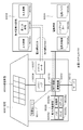
- FIG. 9 schematically shows an example of the configuration of a hybrid vehicle that employs a series hybrid system to which the present technology is applied.
- a series hybrid system is a car that runs on an electric power driving force conversion device using electric power generated by a generator driven by an engine or electric power once stored in a battery.
- the hybrid vehicle 7200 includes an engine 7201, a generator 7202, a power driving force conversion device 7203, a driving wheel 7204a, a driving wheel 7204b, a wheel 7205a, a wheel 7205b, a battery 7208, a vehicle control device 7209, various sensors 7210, and a charging port 7211. Is installed.
- the battery according to the embodiment of the present technology described above is applied to the battery 7208.
- Hybrid vehicle 7200 travels using power driving force conversion device 7203 as a power source.
- An example of the power driving force conversion device 7203 is a motor.
- the electric power / driving force conversion device 7203 is operated by the electric power of the battery 7208, and the rotational force of the electric power / driving force conversion device 7203 is transmitted to the driving wheels 7204a and 7204b.
- the power driving force conversion device 7203 can be applied to either an AC motor or a DC motor by using DC-AC (DC-AC) or reverse conversion (AC-DC conversion) where necessary.
- Various sensors 7210 control the engine speed through the vehicle control device 7209 and control the opening of a throttle valve (throttle opening) (not shown).
- Various sensors 7210 include a speed sensor, an acceleration sensor, an engine speed sensor, and the like.
- the rotational force of the engine 7201 is transmitted to the generator 7202, and the electric power generated by the generator 7202 by the rotational force can be stored in the battery 7208.
- the resistance force at the time of deceleration is applied as a rotational force to the power driving force conversion device 7203, and the regenerative power generated by the power driving force conversion device 7203 by this rotational force is applied to the battery 7208. Accumulated.
- the battery 7208 is connected to an external power source of the hybrid vehicle, so that the battery 7208 can receive power from the external power source using the charging port 211 as an input port and store the received power.
- an information processing device that performs information processing related to vehicle control based on information related to the secondary battery may be provided.
- an information processing apparatus for example, there is an information processing apparatus that displays a remaining battery level based on information on the remaining battery level.
- the technology according to the present technology can be preferably applied to, for example, the battery 7208.
- the battery according to one embodiment is applied to the battery 7208.
- a power storage system 9100 for a house 9001 power is stored from a centralized power system 9002 such as a thermal power generation 9002a, a nuclear power generation 9002b, and a hydropower generation 9002c through a power network 9009, an information network 9012, a smart meter 9007, a power hub 9008, and the like. Supplied to the device 9003. At the same time, power is supplied to the power storage device 9003 from an independent power source such as the home power generation device 9004. The electric power supplied to the power storage device 9003 is stored. Electric power used in the house 9001 is supplied using the power storage device 9003. The same power storage system can be used not only for the house 9001 but also for buildings.
- the house 9001 is provided with a power generation device 9004, a power consumption device 9005, a power storage device 9003, a control device 9010 that controls each device, a smart meter 9007, and a sensor 9011 that acquires various types of information.
- Each device is connected by a power network 9009 and an information network 9012.
- a solar cell, a fuel cell, or the like is used, and the generated power is supplied to the power consumption device 9005 and / or the power storage device 9003.
- the power consuming apparatus 9005 is a refrigerator 9005a, an air conditioner 9005b, a television receiver 9005c, a bath 9005d, or the like.
- the electric power consumption device 9005 includes an electric vehicle 9006.
- the electric vehicle 9006 is an electric vehicle 9006a, a hybrid car 9006b, and an electric motorcycle 9006c.
- the battery which concerns on one Embodiment of this technique mentioned above with respect to the electrical storage apparatus 9003 is applied.
- the smart meter 9007 has a function of measuring the usage amount of commercial power and transmitting the measured usage amount to an electric power company.
- the power network 9009 may be any one or a combination of DC power supply, AC power supply, and non-contact power supply.
- Various sensors 9011 are, for example, human sensors, illuminance sensors, object detection sensors, power consumption sensors, vibration sensors, contact sensors, temperature sensors, infrared sensors, and the like. Information acquired by the various sensors 9011 is transmitted to the control device 9010. Based on the information from the sensor 9011, the weather condition, the condition of the person, and the like can be grasped, and the power consumption device 9005 can be automatically controlled to minimize the energy consumption. Furthermore, the control device 9010 can transmit information on the house 9001 to an external power company or the like via the Internet.
- the power hub 9008 performs processing such as branching of power lines and DC / AC conversion.
- Communication methods of the information network 9012 connected to the control device 9010 include a method using a communication interface such as UART (Universal Asynchronous Receiver-Transmitter), Bluetooth (registered trademark), ZigBee, Wi-Fi.
- a communication interface such as UART (Universal Asynchronous Receiver-Transmitter), Bluetooth (registered trademark), ZigBee, Wi-Fi.
- the Bluetooth method is applied to multimedia communication and can perform one-to-many connection communication.
- ZigBee uses the physical layer of IEEE (Institute of Electrical and Electronics Electronics) (802.15.4).
- IEEE 802.15.4 is the name of a short-range wireless network standard called PAN (Personal Area Network) or W (Wireless) PAN.
- the control device 9010 is connected to an external server 9013.
- the server 9013 may be managed by any one of the house 9001, the electric power company, and the service provider.
- Information transmitted / received by the server 9013 is, for example, information on power consumption information, life pattern information, power charges, weather information, natural disaster information, and power transactions. These pieces of information may be transmitted / received from a power consuming device (for example, a television receiver) in the home, or may be transmitted / received from a device outside the home (for example, a mobile phone). Such information may be displayed on a device having a display function, for example, a television receiver, a mobile phone, a PDA (Personal Digital Assistant) or the like.
- a control device 9010 that controls each unit is configured by a CPU (Central Processing Unit), a RAM (Random Access Memory), a ROM (Read Only Memory), and the like, and is stored in the power storage device 9003 in this example.
- the control device 9010 is connected to the power storage device 9003, the home power generation device 9004, the power consumption device 9005, the various sensors 9011, the server 9013, and the information network 9012.
- the control device 9010 functions to adjust the amount of commercial power used and the amount of power generation. have. In addition, you may provide the function etc. which carry out an electric power transaction in an electric power market.
- electric power can be stored not only in the centralized power system 9002 such as the thermal power 9002a, the nuclear power 9002b, and the hydropower 9002c but also in the power storage device 9003 in the power generation device 9004 (solar power generation, wind power generation). it can. Therefore, even if the generated power of the home power generation apparatus 9004 fluctuates, it is possible to perform control such that the amount of power to be sent to the outside is constant or discharge is performed as necessary.
- the power obtained by solar power generation is stored in the power storage device 9003, and midnight power with a low charge is stored in the power storage device 9003 at night, and the power stored by the power storage device 9003 is discharged during a high daytime charge. You can also use it.
- control device 9010 is stored in the power storage device 9003.
- control device 9010 may be stored in the smart meter 9007, or may be configured independently.
- the power storage system 9100 may be used for a plurality of homes in an apartment house, or may be used for a plurality of detached houses.
- the technology according to the present technology can be preferably applied to the power storage device 9003.
- the battery according to one embodiment can be applied to the power storage device 9003.
- the present technology is applicable not only to large-sized electric vehicles and aircraft, but also to electric motorcycles, electric bicycles, electric tricycles, electric small air vehicles (also referred to as drones), and the like.
- the present technology can also be applied to electronic devices (PCs, smartphones, mobile phones, power tools, toys, etc.) in which secondary batteries can be used. It is also possible to realize the present technology as an electronic device having a battery.
- this technique can also take the following structures.
- a battery element A film exterior material that houses the battery element; A battery comprising: a carbon fiber sheet provided between the battery element and the film sheathing material and including long fibers.
- the battery according to (1) or (2), wherein the long fibers form a bundle.
- the battery element has a flat shape or a square shape, The said carbon fiber sheet is a battery in any one of (1) thru
Landscapes
- Chemical & Material Sciences (AREA)
- Chemical Kinetics & Catalysis (AREA)
- Electrochemistry (AREA)
- General Chemical & Material Sciences (AREA)
- Engineering & Computer Science (AREA)
- Manufacturing & Machinery (AREA)
- Inorganic Chemistry (AREA)
- Materials Engineering (AREA)
- Secondary Cells (AREA)
- Sealing Battery Cases Or Jackets (AREA)
- Cell Separators (AREA)
Abstract
L'invention concerne une cellule, équipée : d'un élément de cellule ; de matériaux extérieurs de film logeant l'élément de cellule ; et de feuilles de fibres de carbone disposées entre l'élément de cellule et les matériaux extérieurs de film, les feuilles de fibres de carbone contenant de longues fibres.
Priority Applications (4)
| Application Number | Priority Date | Filing Date | Title |
|---|---|---|---|
| EP17874926.3A EP3518316A4 (fr) | 2016-11-24 | 2017-10-16 | Cellule et dispositif électronique |
| CN201780065642.1A CN109891628A (zh) | 2016-11-24 | 2017-10-16 | 电池和电子设备 |
| JP2018552459A JP6652201B2 (ja) | 2016-11-24 | 2017-10-16 | 電池および電子機器 |
| US16/353,253 US11056741B2 (en) | 2016-11-24 | 2019-03-14 | Battery and electronic device |
Applications Claiming Priority (2)
| Application Number | Priority Date | Filing Date | Title |
|---|---|---|---|
| JP2016-227437 | 2016-11-24 | ||
| JP2016227437 | 2016-11-24 |
Related Child Applications (1)
| Application Number | Title | Priority Date | Filing Date |
|---|---|---|---|
| US16/353,253 Continuation US11056741B2 (en) | 2016-11-24 | 2019-03-14 | Battery and electronic device |
Publications (1)
| Publication Number | Publication Date |
|---|---|
| WO2018096835A1 true WO2018096835A1 (fr) | 2018-05-31 |
Family
ID=62195502
Family Applications (1)
| Application Number | Title | Priority Date | Filing Date |
|---|---|---|---|
| PCT/JP2017/037394 Ceased WO2018096835A1 (fr) | 2016-11-24 | 2017-10-16 | Cellule et dispositif électronique |
Country Status (5)
| Country | Link |
|---|---|
| US (1) | US11056741B2 (fr) |
| EP (1) | EP3518316A4 (fr) |
| JP (1) | JP6652201B2 (fr) |
| CN (1) | CN109891628A (fr) |
| WO (1) | WO2018096835A1 (fr) |
Cited By (1)
| Publication number | Priority date | Publication date | Assignee | Title |
|---|---|---|---|---|
| JP2024160640A (ja) * | 2023-05-01 | 2024-11-14 | トヨタ自動車株式会社 | 全固体電池の製造方法及び全固体電池 |
Families Citing this family (5)
| Publication number | Priority date | Publication date | Assignee | Title |
|---|---|---|---|---|
| US11539104B2 (en) | 2020-04-20 | 2022-12-27 | Toyota Motor Engineering & Manufacturing North America, Inc. | Battery pillar protector |
| EP4152487A4 (fr) * | 2020-05-15 | 2023-07-19 | Ningde Amperex Technology Ltd. | Film d'emballage, appareil électrochimique et appareil électronique |
| US20240304902A1 (en) * | 2021-11-23 | 2024-09-12 | Lg Energy Solution, Ltd. | Pouch-Type Secondary Battery and Manufacturing Method Therefor |
| US20250125507A1 (en) * | 2022-01-31 | 2025-04-17 | Carl Freudenberg Kg | Energy storage cell |
| CN121355382A (zh) * | 2022-10-18 | 2026-01-16 | 珠海冠宇动力电池有限公司 | 一种电池 |
Citations (4)
| Publication number | Priority date | Publication date | Assignee | Title |
|---|---|---|---|---|
| JPH08171905A (ja) * | 1994-12-16 | 1996-07-02 | Matsushita Electric Ind Co Ltd | シール形鉛蓄電池 |
| JP2012109268A (ja) * | 2012-02-27 | 2012-06-07 | Kuraray Co Ltd | アルカリ電池用セパレータ及びアルカリ一次電池 |
| JP2012155974A (ja) * | 2011-01-25 | 2012-08-16 | Sharp Corp | 非水系二次電池 |
| JP2015233004A (ja) * | 2014-05-16 | 2015-12-24 | 株式会社半導体エネルギー研究所 | 二次電池を備えた電子機器 |
Family Cites Families (10)
| Publication number | Priority date | Publication date | Assignee | Title |
|---|---|---|---|---|
| JPS6168868A (ja) * | 1984-09-12 | 1986-04-09 | Hitachi Ltd | シ−ト状バツテリ− |
| JP4024596B2 (ja) * | 2002-06-03 | 2007-12-19 | 三菱電機株式会社 | 光学機器用反射鏡およびその製造方法 |
| JP2006073334A (ja) * | 2004-09-01 | 2006-03-16 | Mitsubishi Corp | 燃料電池用セパレータ |
| JP4599314B2 (ja) * | 2006-02-22 | 2010-12-15 | 株式会社東芝 | 非水電解質電池、電池パック及び自動車 |
| FR2964256B1 (fr) * | 2010-08-24 | 2012-09-28 | Commissariat Energie Atomique | Accumulateur electrochimique bipolaire a emballage ameliore |
| US9680135B2 (en) * | 2010-09-02 | 2017-06-13 | Intellectual Discovery Co., Ltd. | Pouch-type flexible film battery |
| KR20140052568A (ko) * | 2012-10-25 | 2014-05-07 | 코오롱인더스트리 주식회사 | 이차전지용 파우치 외장재 |
| CN103972437A (zh) * | 2013-02-04 | 2014-08-06 | 北京中瑞蓝科电动汽车技术有限公司 | 一种电动汽车的电池箱及其制作方法 |
| JP2016076359A (ja) * | 2014-10-06 | 2016-05-12 | 株式会社日立製作所 | 全固体リチウム二次電池および蓄電装置 |
| US9768421B2 (en) * | 2014-10-10 | 2017-09-19 | Samsung Electronics Co., Ltd. | Flexible electrode assembly and electrochemical device having the electrode assembly |
-
2017
- 2017-10-16 EP EP17874926.3A patent/EP3518316A4/fr not_active Withdrawn
- 2017-10-16 WO PCT/JP2017/037394 patent/WO2018096835A1/fr not_active Ceased
- 2017-10-16 JP JP2018552459A patent/JP6652201B2/ja active Active
- 2017-10-16 CN CN201780065642.1A patent/CN109891628A/zh active Pending
-
2019
- 2019-03-14 US US16/353,253 patent/US11056741B2/en active Active
Patent Citations (4)
| Publication number | Priority date | Publication date | Assignee | Title |
|---|---|---|---|---|
| JPH08171905A (ja) * | 1994-12-16 | 1996-07-02 | Matsushita Electric Ind Co Ltd | シール形鉛蓄電池 |
| JP2012155974A (ja) * | 2011-01-25 | 2012-08-16 | Sharp Corp | 非水系二次電池 |
| JP2012109268A (ja) * | 2012-02-27 | 2012-06-07 | Kuraray Co Ltd | アルカリ電池用セパレータ及びアルカリ一次電池 |
| JP2015233004A (ja) * | 2014-05-16 | 2015-12-24 | 株式会社半導体エネルギー研究所 | 二次電池を備えた電子機器 |
Non-Patent Citations (1)
| Title |
|---|
| See also references of EP3518316A4 * |
Cited By (3)
| Publication number | Priority date | Publication date | Assignee | Title |
|---|---|---|---|---|
| JP2024160640A (ja) * | 2023-05-01 | 2024-11-14 | トヨタ自動車株式会社 | 全固体電池の製造方法及び全固体電池 |
| JP7768190B2 (ja) | 2023-05-01 | 2025-11-12 | トヨタ自動車株式会社 | 全固体電池の製造方法及び全固体電池 |
| KR102941552B1 (ko) | 2023-05-01 | 2026-03-19 | 도요타 지도샤(주) | 전고체 전지의 제조 방법 및 전고체 전지 |
Also Published As
| Publication number | Publication date |
|---|---|
| EP3518316A4 (fr) | 2020-06-03 |
| US11056741B2 (en) | 2021-07-06 |
| CN109891628A (zh) | 2019-06-14 |
| JPWO2018096835A1 (ja) | 2019-03-28 |
| JP6652201B2 (ja) | 2020-02-19 |
| US20190280253A1 (en) | 2019-09-12 |
| EP3518316A1 (fr) | 2019-07-31 |
Similar Documents
| Publication | Publication Date | Title |
|---|---|---|
| US11631901B2 (en) | Battery, battery pack, electronic device, electric vehicle, electric storage device, and electric power system | |
| US11961999B2 (en) | Positive electrode, battery and method for manufacturing battery, battery pack, electronic device, electric vehicle, electric storage device, and electric power system | |
| JP6652201B2 (ja) | 電池および電子機器 | |
| JP6874404B2 (ja) | 非水電解液電池用の正極、非水電解液電池、電池パック、電子機器、電動車両、蓄電装置および電力システム | |
| JP6414146B2 (ja) | 電解液、電池、電池パック、電子機器、電動車両、蓄電装置および電力システム | |
| WO2018042842A1 (fr) | Batterie, bloc-batterie, appareil électronique, véhicule électrique, dispositif de stockage d'énergie et système d'alimentation | |
| US11742490B2 (en) | Positive electrode, battery, battery pack, electronic device, electric motor vehicle, power storage device, and power system | |
| US11335958B2 (en) | Battery, battery pack, electronic apparatus, electric vehicle, power storage device and power system | |
| JP6554978B2 (ja) | 電池、電池パック、電子機器、電動車両、蓄電装置および電力システム | |
| JP6699736B2 (ja) | 電池、蓄電装置および電動車両 | |
| US12300778B2 (en) | Positive electrode active material, positive electrode, battery, battery pack, electronic device, electric vehicle, power storage device, and power system | |
| US20200058939A1 (en) | Positive electrode active substance, positive electrode, battery, battery pack, electronic device, electric vehicle, electric power storage device, and electric power system | |
| WO2018135061A1 (fr) | Matériau actif d'électrode positive, électrode positive, batterie, bloc-batterie, dispositif électronique, véhicule électrique, dispositif de stockage électrique, et système d'alimentation électrique | |
| WO2018225450A1 (fr) | Matériau actif d'électrode positive, électrode positive, batterie, bloc-batterie, appareil électronique, véhicule électrique, dispositif de stockage d'électricité et système d'alimentation électrique |
Legal Events
| Date | Code | Title | Description |
|---|---|---|---|
| ENP | Entry into the national phase |
Ref document number: 2018552459 Country of ref document: JP Kind code of ref document: A |
|
| 121 | Ep: the epo has been informed by wipo that ep was designated in this application |
Ref document number: 17874926 Country of ref document: EP Kind code of ref document: A1 |
|
| ENP | Entry into the national phase |
Ref document number: 2017874926 Country of ref document: EP Effective date: 20190424 |
|
| NENP | Non-entry into the national phase |
Ref country code: DE |