WO2018096894A1 - Dispositif et procédé de diagnostic de moteur à combustion interne, et dispositif et procédé de commande de moteur à combustion interne - Google Patents
Dispositif et procédé de diagnostic de moteur à combustion interne, et dispositif et procédé de commande de moteur à combustion interne Download PDFInfo
- Publication number
- WO2018096894A1 WO2018096894A1 PCT/JP2017/039567 JP2017039567W WO2018096894A1 WO 2018096894 A1 WO2018096894 A1 WO 2018096894A1 JP 2017039567 W JP2017039567 W JP 2017039567W WO 2018096894 A1 WO2018096894 A1 WO 2018096894A1
- Authority
- WO
- WIPO (PCT)
- Prior art keywords
- cylinder
- internal combustion
- fuel injection
- combustion engine
- cylinders
- Prior art date
- Legal status (The legal status is an assumption and is not a legal conclusion. Google has not performed a legal analysis and makes no representation as to the accuracy of the status listed.)
- Ceased
Links
Images







Classifications
-
- F—MECHANICAL ENGINEERING; LIGHTING; HEATING; WEAPONS; BLASTING
- F02—COMBUSTION ENGINES; HOT-GAS OR COMBUSTION-PRODUCT ENGINE PLANTS
- F02D—CONTROLLING COMBUSTION ENGINES
- F02D41/00—Electrical control of supply of combustible mixture or its constituents
- F02D41/008—Controlling each cylinder individually
- F02D41/0085—Balancing of cylinder outputs, e.g. speed, torque or air-fuel ratio
-
- F—MECHANICAL ENGINEERING; LIGHTING; HEATING; WEAPONS; BLASTING
- F02—COMBUSTION ENGINES; HOT-GAS OR COMBUSTION-PRODUCT ENGINE PLANTS
- F02B—INTERNAL-COMBUSTION PISTON ENGINES; COMBUSTION ENGINES IN GENERAL
- F02B37/00—Engines characterised by provision of pumps driven at least for part of the time by exhaust
- F02B37/12—Control of the pumps
- F02B37/24—Control of the pumps by using pumps or turbines with adjustable guide vanes
-
- F—MECHANICAL ENGINEERING; LIGHTING; HEATING; WEAPONS; BLASTING
- F02—COMBUSTION ENGINES; HOT-GAS OR COMBUSTION-PRODUCT ENGINE PLANTS
- F02D—CONTROLLING COMBUSTION ENGINES
- F02D41/00—Electrical control of supply of combustible mixture or its constituents
- F02D41/0002—Controlling intake air
- F02D41/0007—Controlling intake air for control of turbo-charged or super-charged engines
-
- F—MECHANICAL ENGINEERING; LIGHTING; HEATING; WEAPONS; BLASTING
- F02—COMBUSTION ENGINES; HOT-GAS OR COMBUSTION-PRODUCT ENGINE PLANTS
- F02D—CONTROLLING COMBUSTION ENGINES
- F02D41/00—Electrical control of supply of combustible mixture or its constituents
- F02D41/0025—Controlling engines characterised by use of non-liquid fuels, pluralities of fuels, or non-fuel substances added to the combustible mixtures
- F02D41/0047—Controlling exhaust gas recirculation [EGR]
- F02D41/005—Controlling exhaust gas recirculation [EGR] according to engine operating conditions
- F02D41/0052—Feedback control of engine parameters, e.g. for control of air/fuel ratio or intake air amount
-
- F—MECHANICAL ENGINEERING; LIGHTING; HEATING; WEAPONS; BLASTING
- F02—COMBUSTION ENGINES; HOT-GAS OR COMBUSTION-PRODUCT ENGINE PLANTS
- F02D—CONTROLLING COMBUSTION ENGINES
- F02D41/00—Electrical control of supply of combustible mixture or its constituents
- F02D41/02—Circuit arrangements for generating control signals
- F02D41/14—Introducing closed-loop corrections
- F02D41/1497—With detection of the mechanical response of the engine
- F02D41/1498—With detection of the mechanical response of the engine measuring engine roughness
-
- F—MECHANICAL ENGINEERING; LIGHTING; HEATING; WEAPONS; BLASTING
- F02—COMBUSTION ENGINES; HOT-GAS OR COMBUSTION-PRODUCT ENGINE PLANTS
- F02D—CONTROLLING COMBUSTION ENGINES
- F02D41/00—Electrical control of supply of combustible mixture or its constituents
- F02D41/22—Safety or indicating devices for abnormal conditions
-
- F—MECHANICAL ENGINEERING; LIGHTING; HEATING; WEAPONS; BLASTING
- F02—COMBUSTION ENGINES; HOT-GAS OR COMBUSTION-PRODUCT ENGINE PLANTS
- F02D—CONTROLLING COMBUSTION ENGINES
- F02D41/00—Electrical control of supply of combustible mixture or its constituents
- F02D41/24—Electrical control of supply of combustible mixture or its constituents characterised by the use of digital means
- F02D41/26—Electrical control of supply of combustible mixture or its constituents characterised by the use of digital means using computer, e.g. microprocessor
- F02D41/28—Interface circuits
-
- F—MECHANICAL ENGINEERING; LIGHTING; HEATING; WEAPONS; BLASTING
- F02—COMBUSTION ENGINES; HOT-GAS OR COMBUSTION-PRODUCT ENGINE PLANTS
- F02B—INTERNAL-COMBUSTION PISTON ENGINES; COMBUSTION ENGINES IN GENERAL
- F02B37/00—Engines characterised by provision of pumps driven at least for part of the time by exhaust
- F02B37/12—Control of the pumps
- F02B2037/122—Control of rotational speed of the pump
-
- F—MECHANICAL ENGINEERING; LIGHTING; HEATING; WEAPONS; BLASTING
- F02—COMBUSTION ENGINES; HOT-GAS OR COMBUSTION-PRODUCT ENGINE PLANTS
- F02D—CONTROLLING COMBUSTION ENGINES
- F02D41/00—Electrical control of supply of combustible mixture or its constituents
- F02D41/24—Electrical control of supply of combustible mixture or its constituents characterised by the use of digital means
- F02D41/26—Electrical control of supply of combustible mixture or its constituents characterised by the use of digital means using computer, e.g. microprocessor
- F02D41/28—Interface circuits
- F02D2041/286—Interface circuits comprising means for signal processing
- F02D2041/288—Interface circuits comprising means for signal processing for performing a transformation into the frequency domain, e.g. Fourier transformation
-
- F—MECHANICAL ENGINEERING; LIGHTING; HEATING; WEAPONS; BLASTING
- F02—COMBUSTION ENGINES; HOT-GAS OR COMBUSTION-PRODUCT ENGINE PLANTS
- F02D—CONTROLLING COMBUSTION ENGINES
- F02D2200/00—Input parameters for engine control
- F02D2200/02—Input parameters for engine control the parameters being related to the engine
- F02D2200/021—Engine temperature
-
- F—MECHANICAL ENGINEERING; LIGHTING; HEATING; WEAPONS; BLASTING
- F02—COMBUSTION ENGINES; HOT-GAS OR COMBUSTION-PRODUCT ENGINE PLANTS
- F02D—CONTROLLING COMBUSTION ENGINES
- F02D2200/00—Input parameters for engine control
- F02D2200/02—Input parameters for engine control the parameters being related to the engine
- F02D2200/04—Engine intake system parameters
- F02D2200/0406—Intake manifold pressure
-
- F—MECHANICAL ENGINEERING; LIGHTING; HEATING; WEAPONS; BLASTING
- F02—COMBUSTION ENGINES; HOT-GAS OR COMBUSTION-PRODUCT ENGINE PLANTS
- F02D—CONTROLLING COMBUSTION ENGINES
- F02D2200/00—Input parameters for engine control
- F02D2200/02—Input parameters for engine control the parameters being related to the engine
- F02D2200/10—Parameters related to the engine output, e.g. engine torque or engine speed
- F02D2200/101—Engine speed
-
- F—MECHANICAL ENGINEERING; LIGHTING; HEATING; WEAPONS; BLASTING
- F02—COMBUSTION ENGINES; HOT-GAS OR COMBUSTION-PRODUCT ENGINE PLANTS
- F02D—CONTROLLING COMBUSTION ENGINES
- F02D2200/00—Input parameters for engine control
- F02D2200/70—Input parameters for engine control said parameters being related to the vehicle exterior
- F02D2200/703—Atmospheric pressure
-
- Y—GENERAL TAGGING OF NEW TECHNOLOGICAL DEVELOPMENTS; GENERAL TAGGING OF CROSS-SECTIONAL TECHNOLOGIES SPANNING OVER SEVERAL SECTIONS OF THE IPC; TECHNICAL SUBJECTS COVERED BY FORMER USPC CROSS-REFERENCE ART COLLECTIONS [XRACs] AND DIGESTS
- Y02—TECHNOLOGIES OR APPLICATIONS FOR MITIGATION OR ADAPTATION AGAINST CLIMATE CHANGE
- Y02T—CLIMATE CHANGE MITIGATION TECHNOLOGIES RELATED TO TRANSPORTATION
- Y02T10/00—Road transport of goods or passengers
- Y02T10/10—Internal combustion engine [ICE] based vehicles
- Y02T10/12—Improving ICE efficiencies
-
- Y—GENERAL TAGGING OF NEW TECHNOLOGICAL DEVELOPMENTS; GENERAL TAGGING OF CROSS-SECTIONAL TECHNOLOGIES SPANNING OVER SEVERAL SECTIONS OF THE IPC; TECHNICAL SUBJECTS COVERED BY FORMER USPC CROSS-REFERENCE ART COLLECTIONS [XRACs] AND DIGESTS
- Y02—TECHNOLOGIES OR APPLICATIONS FOR MITIGATION OR ADAPTATION AGAINST CLIMATE CHANGE
- Y02T—CLIMATE CHANGE MITIGATION TECHNOLOGIES RELATED TO TRANSPORTATION
- Y02T10/00—Road transport of goods or passengers
- Y02T10/10—Internal combustion engine [ICE] based vehicles
- Y02T10/40—Engine management systems
Definitions
- the present invention relates to an internal combustion engine diagnosis device and method, and an internal combustion engine control device and control method.
- the present invention relates to a diagnostic device and a diagnostic method for diagnosing the combustion state of fuel in each cylinder of a multi-cylinder internal combustion engine, and a control device and a control method for controlling the internal combustion engine according to the result of the diagnosis.
- a fuel supply amount (hereinafter also referred to as a fuel injection amount) directed to each cylinder controls the valve opening time of the injector according to the fuel pressure in the fuel supply system. (For example, refer patent document 1).
- the fuel combustion in that cylinder is It is not performed (the target combustion amount cannot be obtained).
- the target combustion amount cannot be obtained.
- the cause of this failure is not only the variation in the fuel injection amount from each injector, but also the influence of the fuel properties.
- JP 2001-65397 A Japanese Patent No. 5770657
- the inventors of the present invention diagnose the combustion state of fuel in each cylinder (for example, diagnose whether or not the fuel injection amount from each injector varies), and an internal combustion engine according to the result of the diagnosis (For example, correction of the fuel injection amount that eliminates the variation in the fuel injection amount from each injector) was considered.
- a multi-cylinder internal combustion engine equipped with an exhaust turbine supercharger hereinafter sometimes referred to as a turbocharger
- turbocharger there is a correlation between the combustion state of fuel in each cylinder and fluctuations in the rotational speed of the turbocharger
- Patent Document 2 discloses that the rotational speed of a turbocharger is detected by a turbo sensor. However, in Patent Document 2, the disconnection of the turbo sensor is detected by an output signal from the turbo sensor. However, there is no disclosure regarding the diagnosis of the combustion state of the fuel in each cylinder and the control of the internal combustion engine according to the diagnosis result.
- the present invention has been made in view of the above points, and an object of the present invention is to provide an internal combustion engine diagnosis apparatus and diagnosis that can appropriately perform diagnosis of the combustion state of fuel in each cylinder of a multi-cylinder internal combustion engine. It is an object of the present invention to provide an internal combustion engine control device and a control method capable of appropriately controlling the internal combustion engine according to the method and the result of the diagnosis.
- a solution means of the present invention is an internal combustion engine diagnosis apparatus for diagnosing the combustion state of fuel in each cylinder of a multi-cylinder internal combustion engine equipped with an exhaust turbine supercharger, Rotational speed detecting means for outputting a signal corresponding to the rotational speed of the turbine supercharger or a signal correlated with fluctuations in the rotational speed of the exhaust turbine supercharger, and frequency characteristics of the signal output from the rotational speed detecting means And a combustion state diagnosing unit for diagnosing variation in the combustion state of the fuel between the cylinders by performing frequency analysis by fast Fourier transform.
- the combustion state diagnosis unit outputs a signal output from the rotational speed detection means (a signal corresponding to the rotational speed of the exhaust turbine supercharger or a signal correlated with fluctuations in the rotational speed of the exhaust turbine supercharger).
- a signal output from the rotational speed detection means a signal corresponding to the rotational speed of the exhaust turbine supercharger or a signal correlated with fluctuations in the rotational speed of the exhaust turbine supercharger.
- the combustion state diagnostic unit obtains an operating point corresponding to the complex plane by performing frequency analysis by the fast Fourier transform, and a coordinate axis of the complex plane of a vector from the origin on the complex plane to the operating point; It is preferable that the variation in the combustion state of the fuel between the cylinders is diagnosed based on the angle formed by and the vector length.
- the combustion state diagnosis unit identifies a cylinder in which the combustion state of fuel is different from other cylinders based on an angle formed with the coordinate axis of the complex plane in the vector, and based on the vector length
- the deviation between the state quantity related to the combustion of the fuel in the specified cylinder and the state quantity in the other cylinder is specified.
- the cylinder on which the fuel combustion state is different from the other cylinders can be specified by the vector on the complex plane, and the state quantity related to the fuel combustion in the specified cylinder can be determined. Deviations from the state quantities in other cylinders can be specified. That is, the variation in the combustion state of the fuel between the cylinders can be diagnosed in detail.
- the combustion state diagnosing unit includes a frequency intensity obtained by dividing a combustion frequency obtained from a signal output from the rotation speed detection means by the number of cylinders of the multi-cylinder internal combustion engine, and the combustion frequency as the multi-cylinder internal combustion engine.
- the intensity of the former frequency is higher than the intensity of the latter frequency
- the fuel in one of the cylinders is compared.
- the combustion state of the fuel is different from the combustion state of the fuel in each of the other cylinders, or the combustion state of the fuel in each of the plurality of cylinders in which the combustion stroke continues among the cylinders is the combustion of the fuel in each of the other cylinders It is preferably configured to diagnose that the condition is different.
- the combustion state diagnosing unit includes a frequency intensity obtained by dividing a combustion frequency obtained from a signal output from the rotation speed detection means by the number of cylinders of the multi-cylinder internal combustion engine, and the combustion frequency as the multi-cylinder internal combustion engine.
- the intensity of the latter frequency is higher than the intensity of the former frequency, the piston of each cylinder reciprocates in the same phase. It is preferable that the fuel combustion state in each of the plurality of cylinders that move and the combustion strokes do not continue is diagnosed as being different from the fuel combustion state in each of the other cylinders.
- an execution permission condition for combustion state diagnosis is given to at least one state quantity of the engine speed, engine load, cooling water temperature, intake air pressure, exhaust pressure, intake air temperature, and atmospheric pressure of the multi-cylinder internal combustion engine.
- the combustion state diagnosis unit is configured to diagnose a variation in the combustion state of the fuel between the cylinders when a condition for permitting execution of the combustion state diagnosis is satisfied.
- the state quantity may affect the reliability of the combustion state diagnosis. Therefore, only when the reliability of the combustion state diagnosis is within the range of the state quantity that can sufficiently ensure the combustion state diagnosis, a condition for permitting execution of the combustion state diagnosis is given to the state quantity so as to permit the diagnosis of the variation in the combustion state. I have to. That is, in the situation where the state quantity is a value that adversely affects the reliability of the combustion state diagnosis, the combustion state diagnosis is prohibited. Thereby, the reliability of the combustion state diagnosis can be sufficiently ensured.
- the multi-cylinder internal combustion engine includes an EGR device that recirculates exhaust gas in an exhaust system to an intake system, and the combustion state diagnosis unit is provided with a condition that recirculation of exhaust gas by the EGR device is stopped. Furthermore, it is preferable that the fuel combustion state variation between the cylinders is diagnosed.
- the rotational speed detection outputs a signal corresponding to the rotational speed of the exhaust turbine supercharger.
- the means is arranged in the vicinity of the high-pressure side exhaust turbine supercharger and outputs a signal corresponding to the rotational speed of the high-pressure side exhaust turbine supercharger.
- the present invention utilizes a phenomenon in which the rotational speed of the exhaust turbine supercharger varies due to energy pulsation during exhaust blowdown for each cylinder. For this reason, the reliability of the combustion state diagnosis is ensured by arranging the rotational speed detection means in the vicinity of the high-pressure side exhaust turbine supercharger where the fluctuation of the rotational speed is greatly influenced by the energy pulsation. can do.
- the diagnostic method performed in the above-described internal combustion engine diagnostic apparatus is also within the scope of the technical idea of the present invention. That is, a diagnostic method for an internal combustion engine for diagnosing the combustion state of fuel in each cylinder of a multi-cylinder internal combustion engine equipped with an exhaust turbine supercharger, the signal corresponding to the rotational speed of the exhaust turbine supercharger or the This is an internal combustion engine diagnosis method for diagnosing variations in the combustion state of fuel between cylinders by performing frequency analysis on the frequency characteristics of a signal correlated with fluctuations in the rotational speed of the exhaust turbine supercharger by fast Fourier transform.
- the combustion of fuel in each cylinder can be effectively performed by using a signal corresponding to the rotational speed of the exhaust turbine supercharger or a signal correlated with fluctuations in the rotational speed of the exhaust turbine supercharger. It is possible to properly diagnose the condition.
- control device that controls the internal combustion engine in accordance with the diagnosis result of the internal combustion engine diagnostic device is also within the scope of the technical idea of the present invention.
- the control device of the internal combustion engine includes a variation elimination correction unit that corrects a control amount for changing the combustion state of the fuel for each cylinder so as to eliminate variation in the combustion state of the fuel between the cylinders. .
- the variation elimination correction unit corrects the control amount that changes the combustion state of the fuel according to the diagnosis result, and the variation in the combustion state of the fuel between the cylinders is eliminated. For this reason, the combustion of fuel in each cylinder is optimized, and it is possible to suppress a decrease in engine output, an increase in rotational fluctuation, a deterioration in exhaust emission, and the like.
- the variation eliminating correction unit is an exhaust gas adjusted by the opening of the wastegate valve or the variable displacement mechanism. It is preferable that the control amount is corrected according to the flow path area.
- the variation elimination correction unit corrects the control amount, so that the control amount can be optimized.
- control method for controlling the internal combustion engine in accordance with the diagnosis result of the internal combustion engine diagnosis method described above is also within the scope of the technical idea of the present invention. That is, the control method of the internal combustion engine corrects the control amount for changing the combustion state of the fuel for each cylinder so as to eliminate the variation in the combustion state of the fuel between the cylinders.
- this control method corrects the control amount that changes the combustion state of the fuel according to the diagnosis result, and eliminates the variation in the combustion state of the fuel between the cylinders. For this reason, it is possible to suppress a decrease in engine output, an increase in rotational fluctuation, a deterioration in exhaust emission, and the like.
- the following diagnostic apparatus is also within the scope of the technical idea of the present invention. That is, it is an internal combustion engine diagnosis device that diagnoses the combustion state of fuel in each cylinder of a multi-cylinder internal combustion engine equipped with an exhaust turbine supercharger, and outputs a signal corresponding to the rotational speed of the multi-cylinder internal combustion engine.
- a combustion state diagnosis unit for diagnosing the combustion state of fuel in each cylinder.
- a control device that controls the internal combustion engine in accordance with the result of diagnosis by the internal combustion engine diagnostic device is also within the scope of the technical idea of the present invention. That is, the total fuel supply amount supplied to each cylinder during one cycle of the multi-cylinder internal combustion engine is divided by the number of cylinders to obtain an average fuel supply amount, and the target fuel in each cylinder determined according to the required output
- the control apparatus for an internal combustion engine includes a fuel supply amount correction unit that corrects the fuel supply amount for each cylinder by a deviation between the supply amount and the average fuel supply amount.
- the fuel supply amount correction unit corrects the fuel supply amount in each cylinder according to the diagnosis result, and adjusts the actual total fuel supply amount to the total fuel supply amount according to the required output. It becomes possible. As a result, a total fuel supply amount corresponding to the required output can be obtained.
- the diagnosis of the combustion state according to the present invention can also be used for detection of misfire caused by a change in fuel properties (for example, cetane number of fuel).
- FIG. 6 is a graph showing a comparison of the intensities of frequencies F1 to F4 when the fuel injection amount in each of the two cylinders in which the combustion stroke is not continuous among the four cylinders is different from the fuel injection amount in each of the other two cylinders. .
- FIG. 1 It is a figure showing the operating point made to respond
- the operating point corresponding to the complex plane by the fast Fourier transform is FIG.
- the operating point corresponding to the complex plane by the fast Fourier transform is FIG.
- FIG. 1 It is a figure which shows an example of a total fuel injection amount calculation map. It is a flowchart figure which shows the procedure of the diagnostic operation and correction
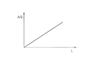
- FIG. It is a figure which shows an example of the relationship between the scalar quantity L by the coefficient a, and deviation
- DELTA shift amount
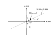
- FIG. It is a figure showing the complex plane of F2 for demonstrating the method of the diagnostic method 2.
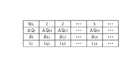
- FIG. It is a figure which shows the table
- FIG. 1 It is a figure for demonstrating the change of the exhaust gas flow path area of a waste gate valve periphery accompanying the change of the fuel injection amount. It is a figure which shows schematic structure of the turbocharger periphery of the engine which concerns on the modification 4. FIG.
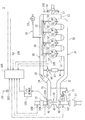
- FIG. 1 is a diagram illustrating a schematic configuration of an engine 1 according to the present embodiment. This engine 1 is used, for example, for ships.
- an engine 1 includes an engine main body 10 and combustion chambers 11 of four cylinders # 1, # 2, # 3, and # 4 formed in the engine main body 10. Are provided with an intake system 20 that guides intake air to 11, and an exhaust system 30 that exhausts exhaust gas generated in the combustion chambers 11, 11,.
- the engine body 10 includes a cylinder block 12 having cylinders # 1 to # 4, a cylinder head (not shown), and the like.
- the intake system 20 includes an intake pipe 21 and an intake manifold 22, and guides outside air to the combustion chambers 11, 11,... Of the cylinders # 1 to # 4 through the intake pipe 21 and the intake manifold 22.
- the intake pipe 21 includes an air filter 23, a compressor wheel 41 of an turbocharger (exhaust turbine supercharger) 40, an intercooler 24, a diesel throttle 25, and the like in order from the upstream side to the downstream side in the flow direction of the intake air. Is provided.
- the exhaust system 30 includes an exhaust pipe 31 and an exhaust manifold 32 and exhausts exhaust gas to the atmosphere via the exhaust manifold 32 and the exhaust pipe 31.
- the exhaust pipe 31 is provided with a turbine wheel 42 of the turbocharger 40, an exhaust purification device 33, and the like in order from the upstream side to the downstream side in the exhaust gas flow direction.
- the turbocharger 40 is for forcibly sending (supercharging) the intake air into the combustion chambers 11, 11,... Of the cylinders # 1 to # 4 using the fluid energy of the exhaust gas.
- the turbine wheel 42 is rotated by the fluid energy of the exhaust gas discharged from the combustion chambers 11, 11,... Of the engine body 10 to the exhaust pipe 31.
- the compressor wheel 41 is connected to the turbine wheel 42 via a rotating shaft 43 so as to rotate together with the turbine wheel 42.
- the engine body 10 is provided with a fuel supply device 50 for supplying fuel to the combustion chambers 11, 11,... Of the cylinders # 1 to # 4.
- the fuel supply device 50 is a common rail type fuel supply device, and a common rail 51 that stores fuel of a predetermined pressure, and a combustion chamber 11 for injecting fuel stored in the common rail 51 into the combustion chambers 11, 11,. , 11,... And injectors 52, 52,..., And a high-pressure fuel pump 53 that pressurizes fuel stored in a fuel tank (not shown) and pumps the fuel to the common rail 51.
- the intake pipe 21 and the exhaust pipe 31 are connected by an exhaust recirculation pipe (EGR pipe) 61.
- the EGR pipe 61 lowers the combustion temperature by causing a part of the exhaust gas to recirculate to the intake system 20 and supplying it to the combustion chambers 11, 11,.
- the EGR pipe 61 is provided with an EGR valve 62 whose opening is adjusted by electronic control, and an EGR cooler 63 for cooling the exhaust gas passing through the EGR pipe 61.
- EGR pipe 61, EGR valve 62, EGR cooler 63 and the like constitute an EGR device (exhaust gas recirculation device) 60.
- the exhaust pipe 31 is provided with an exhaust bypass pipe 71 through which a part of the exhaust gas flows by bypassing the turbine wheel 42 of the turbocharger 40.
- the exhaust bypass pipe 71 has a wastegate valve 72. Is provided. An intake pressure in the intake pipe 21 is introduced into the actuator 73 of the waste gate valve 72, and a diaphragm in the actuator 73 is activated in accordance with the introduced intake pressure, so that the waste gate valve 72 is operated. Opening and closing operations are performed.
- the waste gate valve 72 is opened, a part of the exhaust gas flows through the exhaust bypass pipe 71 and bypasses the turbine wheel 42 of the turbocharger 40. Thereby, the increase in the rotational speed of the turbine wheel 42 is suppressed, and a stable supercharging pressure can be obtained.
- the engine ECU 100 that controls the operation of the engine 1 includes an output operation member 101, an engine rotation speed sensor (internal combustion engine rotation speed detection means) 102, a load state detection member 103, a turbo rotation speed sensor (supercharger rotation speed detection means). 104, a coolant temperature sensor 105, an intake pressure sensor 106, an exhaust pressure sensor 107, an intake temperature sensor 108, and an atmospheric pressure sensor 109 are electrically connected to each other.
- the output operation member 101 is composed of an accelerator lever or an accelerator pedal that can be manually operated, for example.
- the engine rotational speed sensor 102 is constituted by an electromagnetic pickup, and outputs a pulse signal corresponding to the rotational speed of the crankshaft 13 of the engine 1.
- an NE rotor 14 in which a plurality of convex portions and concave portions are alternately provided along the outer peripheral edge is provided on the crankshaft 13 so as to be integrally rotatable, and faces the outer peripheral edge of the NE rotor 14.
- the engine speed sensor 102 is arranged.
- a pulse signal corresponding to the engine rotation speed is output from the engine rotation speed sensor 102.
- the load state detection member 103 is an accelerator opening sensor that detects an operation amount (opening) of the output operation member 101, and outputs a signal corresponding to a load state of the engine body 10.
- the turbo rotational speed sensor 104 is constituted by an electromagnetic pickup and is disposed to face the blades of the compressor wheel 41. For this reason, every time the blade passes near the turbo rotation speed sensor 104 by the rotation of the compressor wheel 41, a pulse signal is output from the turbo rotation speed sensor 104. That is, the turbo rotation speed sensor 104 is configured to output a pulse signal corresponding to the rotation speed of the turbocharger 40. An output signal from the turbo rotation speed sensor 104 is transmitted to the F / V converter 110.
- the F / V converter 110 converts the pulse signal output from the turbo rotational speed sensor 104 into frequency data, and the converted frequency data is transmitted to the engine ECU 100.
- the cooling water temperature sensor 105 outputs a signal corresponding to the cooling water temperature of the engine 1.
- the intake pressure sensor 106 outputs a signal corresponding to the intake pressure on the downstream side of the air filter 23 in the intake pipe 21.
- the exhaust pressure sensor 107 outputs a signal corresponding to the exhaust pressure on the exhaust pipe 31 downstream of the turbine wheel 42 and upstream of the exhaust purification device 33.
- the intake air temperature sensor 108 outputs a signal corresponding to the intake air temperature upstream of the air filter 23 in the intake pipe 21.
- the atmospheric pressure sensor 109 outputs a signal corresponding to the atmospheric pressure.
- the Engine ECU100 has a calculating part (CPU) and a storage part.
- the storage unit includes a ROM that stores a control program, control data, and the like, an EEPROM that stores the setting values and the like that are not lost even when the power is turned off, and the setting values can be rewritten, and the arithmetic unit It has RAM etc. which hold
- the engine ECU 100 is configured to perform basic control of the fuel supply state of the fuel supply device 50 in accordance with the operation amount of the output operation member 101. Specifically, the engine ECU 100 determines that each of the injectors 52, 52,... Performs predetermined fuel injection according to the operation amount of the output operation member 101 detected by the load state detection member 103. Controls the electromagnetic solenoid or piezo element provided in. At the same time, the high pressure fuel pump 53 is controlled to control the fuel pressure in the common rail 51. Further, the engine ECU 100 controls the opening degree of the EGR valve 62 in accordance with the operating state of the engine 1.
- the engine ECU 100 diagnoses the combustion state of the fuel in the combustion chambers 11, 11,... Of the cylinders # 1 to # 4, and the injectors 52, 52 according to the diagnosis result. ,... Is corrected.
- the combustion state diagnosis operation and the fuel injection amount correction operation will be described later.
- each cylinder # 1 to ## is analyzed by frequency analysis of the frequency characteristics of the signal output from the turbo rotational speed sensor 104 or the engine rotational speed sensor 102 by fast Fourier transform.
- the variation of the combustion state of the fuel between 4 is diagnosed.
- the turbo rotational speed sensor 104 or the engine rotational speed sensor 102 is correlated with the rotational speed detecting means (signal according to the rotational speed of the exhaust turbine supercharger or fluctuations in the rotational speed of the exhaust turbine supercharger) in the present invention. It corresponds to a certain speed (rotation speed detecting means for outputting a signal corresponding to the engine speed).
- the engine ECU 100 diagnoses the variation in the combustion state of the fuel between the cylinders # 1 to # 4. For this reason, the functional part of the engine ECU 100 that executes the diagnosis of the variation in the combustion state corresponds to the combustion state diagnosis unit referred to in the present invention. That is, the engine ECU 100 is an example of a diagnostic device according to the present invention.
- diagnosis of the variation in the combustion state of fuel in each cylinder # 1 to # 4 the fuel injection amount from each injector 52, 52,...
- diagnosis of variation in (state quantity) the fuel injection amount from each injector 52, 52,...
- the F / V converter 110 converts the signal output from the turbo rotation speed sensor 104 to analyze the order of the turbo rotation speed signal that has been converted into frequency data, and then analyzes the turbo rotation speed signal, thereby analyzing each cylinder # 1.
- the amount of energy given to the turbine wheel 42 of the turbocharger 40 by the exhaust gas discharged from # 4 is evaluated. This energy is obtained by the combustion of fuel in the combustion chambers 11, 11,... Of the cylinders # 1 to # 4.
- the combustion frequency f cmb is calculated by the following equation (1).
- Z is the number of cylinders
- Nt is the rotational speed of the turbocharger 40
- “2” is the number of revolutions per cycle of the engine 1.
- the rotational speed of the turbocharger 40 varies according to the rotational speed of the engine 1. That is, when the exhaust gas discharged from the combustion chamber 11 by the exhaust stroke of the engine 1 reaches the turbine wheel 42 of the turbocharger 40, the rotational speed of the turbocharger 40 increases, and during other periods, the rotation of the turbocharger 40 The speed will drop. For this reason, the cycle of fluctuations in the rotational speed of the turbocharger 40 is correlated with the rotational speed of the engine 1. Therefore, the combustion frequency f cmb can also be calculated by replacing the rotational speed Nt of the turbocharger 40 in the equation (1) with the rotational speed Ne of the engine 1.
- the combustion frequency f cmb calculated by the equation (1) was divided by “4”, “2”, “1.5”, and “1”, respectively.
- Four types of frequencies F1, F2, F3, and F4 are obtained by the following equations (2) to (5). That is, the frequency F1 is a frequency obtained by dividing the combustion frequency f cmb by the number of cylinders of the engine 1, and the frequency F2 is a frequency obtained by dividing the combustion frequency f cmb by a value of “1 ⁇ 2” of the number of cylinders of the engine 1.
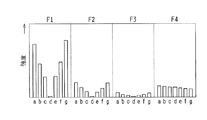
- FIG. 2 shows the magnitudes of the frequencies F1 to F4 when the fuel injection amount in only one cylinder among the four cylinders (the fuel injection amount from the injector 52) is different from the fuel injection amounts in the other three cylinders. It is a graph for comparing (hereinafter sometimes referred to as intensity). The graph shown in FIG. 2 is a bar graph showing the intensities of the frequencies F1 to F4 obtained by experiments or simulations.
- FIG. 2 shows three stages as an example in which the fuel injection amount in only one cylinder is larger than the fuel injection amounts in the other three cylinders (the fuel injection amounts in the other three cylinders are substantially the same).
- the fuel injection amount in only one cylinder is less than the fuel injection amount in each of the other three cylinders, and for each of the cases where the fuel injection amounts in all the cylinders are the same.
- “A”, “b” and “c” in the figure are cases where the fuel injection amount in only one cylinder is larger than the fuel injection amounts in the other three cylinders.
- the deviation amount of the fuel injection amount between the cylinders (the deviation amount between the fuel injection amount in the one cylinder and the fuel injection amount in each of the other three cylinders) is increased.
- “e”, “f”, and “g” in the figure are cases where the fuel injection amount in only one cylinder is smaller than the fuel injection amounts in the other three cylinders, and “e”, “f”.
- the amount of deviation of the fuel injection amount between the cylinders is increased in the order of “g”. Note that “d” in the figure is the case where the fuel injection amounts in all the cylinders are the same.
- the frequency when the fuel injection amount in each of the two cylinders in which the combustion stroke continues is different from the fuel injection amount in each of the other two cylinders (the fuel injection amounts in the other two cylinders are substantially the same).
- F1 to F4 were the same as those shown in FIG.
- the order of the combustion stroke is the first cylinder # 1 ⁇ the third cylinder # 3 ⁇ the second cylinder # 2 ⁇ the fourth cylinder # 4
- the fuel injection amount in each of # 3 is different from the fuel injection amount in each of the second cylinder # 2 and the fourth cylinder # 4.
- FIG. 3 compares the intensities of the frequencies F1 to F4 when the fuel injection amount in each of the two cylinders of the four cylinders where the combustion stroke is not continuous differs from the fuel injection amount in each of the other two cylinders. It is a graph. For example, when the order of the combustion stroke is the first cylinder # 1 ⁇ the third cylinder # 3 ⁇ the second cylinder # 2 ⁇ the fourth cylinder # 4, the first cylinder # 1 and the second cylinder # 4 For example, the fuel injection amount in each of # 2 is different from the fuel injection amount in each of the third cylinder # 3 and the fourth cylinder # 4.
- the graph shown in FIG. 3 is also a bar graph showing the intensities of the frequencies F1 to F4 obtained by experiments or simulations.
- FIG. 3 shows a case where the fuel injection amount in each of the two cylinders where the combustion stroke is not continuous is larger than the fuel injection amount in each of the other two cylinders (the fuel injection amounts in the other two cylinders are substantially the same).
- 3 steps as an example three steps as an example when the fuel injection amount in each of the two cylinders where the combustion stroke is not continuous is smaller than the fuel injection amount in each of the other two cylinders, and fuel injection in all the cylinders.
- “A”, “b”, and “c” in the figure are cases where the fuel injection amount in each of the two cylinders where the combustion stroke is not continuous is larger than the fuel injection amount in each of the other two cylinders.
- the fuel injection amount in only one cylinder is the fuel injection quantity in each of the other three cylinders. If the fuel injection amount in each of the two cylinders in which the combustion stroke continues is different from the fuel injection amount in each of the other two cylinders, the fuel in each of the two cylinders in which the combustion stroke does not continue When the injection amount is different from the fuel injection amount in each of the other two cylinders), a unique operating point appears.
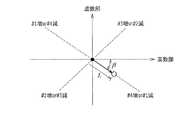
- FIG. 4 shows operating points obtained by expanding the frequency characteristic of the frequency F1 into a Fourier series and plotting it on a complex plane.
- the operating point when the fuel injection amounts in all cylinders are the same is located at the origin on the complex plane (see “ ⁇ ” in FIG. 4).
- the operating point is not located at the origin on the complex plane and deviates from the fuel injection amount. This is the position corresponding to the cylinder in which the occurrence occurs and the amount of deviation.
- “ ⁇ ” in FIG. 4 is a case where the fuel injection amount in only one cylinder is different from the fuel injection amount in each of the other three cylinders, and the fuel injection amount in the first cylinder # 1 is different from that in the other cylinders.
- the operating point when the fuel injection amount in each of the three cylinders is small is shown. Further, the distance L from the origin at this operating point represents the deviation amount of the fuel injection amount (the deviation amount between the fuel injection amount in the first cylinder # 1 and the fuel injection amount in each of the other three cylinders). .
- a similar operating point appears when the fuel injection amount in the fourth cylinder # 4 is larger than the fuel injection amounts in the other three cylinders.
- the fuel injection amount in the second cylinder # 2 is larger than the fuel injection amount in each of the other three cylinders, or the fuel injection amount in the third cylinder # 3 is each of the other three cylinders.
- the operating point appears on the operating line indicated by the broken line in the third quadrant of the complex plane.
- the fuel injection amount in the fourth cylinder # 4 is larger than the fuel injection amounts in the other three cylinders, or the first cylinder # 1.
- the operating point appears on the operating line indicated by the broken line in the fourth quadrant of the complex plane.
- the quadrant of the operating point is specified by the angle (angle ⁇ in FIG. 4) formed by the coordinate axis of the complex plane (for example, the coordinate axis of the real part).
- Cylinders in which the fuel injection amount is different due to ⁇ one cylinder whose fuel injection amount is different from the fuel injection amount in each of the other three cylinders
- ⁇ one cylinder whose fuel injection amount is different from the fuel injection amount in each of the other three cylinders
- a fuel injection amount deviation amount a fuel injection amount deviation amount between one cylinder and each of the other three cylinders
- the cylinder in which the combustion state of the fuel is different from the other cylinders is specified based on the angle formed by the coordinate axis of the complex plane in the vector, and the fuel in the specified cylinder is determined based on the vector length. It is possible to specify the deviation between the state quantity related to combustion (fuel injection quantity in the present embodiment) and the state quantity (fuel injection quantity) in other cylinders (combustion state diagnosis unit referred to in the present invention) Function of).
- angle ⁇ changes according to the engine speed.
- an angle correction amount corresponding to the engine rotational speed is obtained in advance by experiments or the like so that the relationship between the position of the quadrant where the operating point exists and the cylinder in which the fuel injection amount is different can be obtained appropriately. It is preferable to correct the direction of the vector (the inclination of each working line) by this angle correction amount. For example, in the case of this embodiment, the higher the engine rotational speed, the more the vector direction shifts in the clockwise direction in FIG.
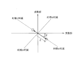
- FIG. 5 shows a case where the fuel injection amount in each of the two cylinders in which the combustion stroke continues is different from the fuel injection amount in each of the other two cylinders.
- the operating point “ ⁇ ” indicates the first cylinder # 1 and the fuel injection amount in the third cylinder # 3 are smaller than the fuel injection amounts in the other two cylinders, and the fuel in the first cylinder # 1.
- the injection amount and the fuel injection amount in the third cylinder # 3 are substantially the same (the decrease amount of the fuel injection amount in the first cylinder # 1 and the decrease amount of the fuel injection amount in the third cylinder # 3). Represents the operating point.
- the vector from the origin to this operating point “ ⁇ ” is a vector on the third quadrant side (the vector on the operating line in the third quadrant).
- the vector from the origin to the operating point “ ⁇ ”) and the vector on the fourth quadrant side (the vector on the operating line in the fourth quadrant, the vector going from the origin to the operating point “ ⁇ ”).
- the fuel injection amount in the third cylinder # 3 is smaller than the fuel injection amounts in the second cylinder # 2 and the fourth cylinder # 4.
- the length of this vector corresponds to the amount of deviation between the fuel injection amount in the third cylinder # 3 and the fuel injection amounts in the second cylinder # 2 and the fourth cylinder # 4. .
- the fuel injection amount in the first cylinder # 1 is smaller than the fuel injection amounts in the second cylinder # 2 and the fourth cylinder # 4.
- the length of this vector is the amount of deviation between the fuel injection amount in the first cylinder # 1 and the fuel injection amounts in the second cylinder # 2 and the fourth cylinder # 4. It corresponds to.
- the angle ⁇ 1 in FIG. 5 indicates that the fuel injection amount in the third cylinder # 3 is smaller than the fuel injection amounts in the second cylinder # 2 and the fourth cylinder # 4.
- the angle ⁇ 2 indicates that the fuel injection amount in the first cylinder # 1 is smaller than the fuel injection amounts in the second cylinder # 2 and the fourth cylinder # 4. Since the amount of decrease in the fuel injection amount in the first cylinder # 1 and the amount of decrease in the fuel injection amount in the third cylinder # 3 are substantially the same, the vector from the origin to the operating point “ ⁇ ”
- the angle ⁇ is an intermediate angle between the angles ⁇ 1 and ⁇ 2. Therefore, when the fuel injection amount in the third cylinder # 3 and the fuel injection amount in the first cylinder # 1 are different from each other, the vector angle ⁇ from the origin to the operating point “ ⁇ ” is also Will be different accordingly.
- the operating point “ ⁇ ” in FIG. 5 indicates the amount of decrease in the fuel injection amount in the first cylinder # 1 (the amount of deviation from the fuel injection amount in the second cylinder # 2 and the fourth cylinder # 4) and the third. This is a case where the ratio of the amount of decrease in fuel injection amount in No. cylinder # 3 (also the amount of deviation from the fuel injection amount in No. 2 cylinder # 2 and No. 4 cylinder # 4) is 2: 3.
- the angle of the vector from the origin to the operating point “ ⁇ ” corresponds to this ratio. Further, by decomposing this vector into vectors on each operating line, the amount of divergence between the first cylinder # 1 and the third cylinder # 3 (the fuel in the second cylinder # 2 and the fourth cylinder # 4). A deviation amount with respect to the injection amount) can be calculated.
- the operating point “ ⁇ ” in FIG. 5 indicates that the ratio of the decrease in the fuel injection amount in the first cylinder # 1 and the decrease in the fuel injection amount in the third cylinder # 3 is 5: 2.
- the angle of the vector from the origin to the operating point “ ⁇ ” corresponds to this ratio.
- the deviation amounts of the first cylinder # 1 and the third cylinder # 3 in the second cylinder # 2 and the fourth cylinder # 4). The amount of deviation from the fuel injection amount) can be calculated.
- the operating angle ⁇ in the complex plane of F1 is The ratio of the fuel injection amount is represented, and the vector length represents the deviation amount of the injection amount.
- FIG. 6 shows a case where the fuel injection amount in each of the two cylinders where the combustion stroke is not continuous is different from the fuel injection amount in each of the other two cylinders.
- the operating point “ ⁇ ” indicates the first cylinder # 1 is different from the fuel injection amount in the second cylinder # 2 and the third cylinder # 3, and the fuel injection amount in the fourth cylinder # 4 is different from the second cylinder # 2 and the third cylinder # 3.
- a case where the fuel injection amount is different from that in the third cylinder # 3 is shown.
- the length of the vector from the origin toward the operating point “ ⁇ ” corresponds to the deviation between the fuel injection amount in the first cylinder # 1 and the fuel injection amount in the fourth cylinder # 4. .
- the fuel injection amount in the first cylinder # 1 and the fuel injection amount in the fourth cylinder # 4 are both smaller than the fuel injection amounts in the second cylinder # 2 and the third cylinder # 3.
- the operating point appears in the fourth quadrant (see operating point “ ⁇ ”). Then, the position of the operating point is different on the operating line depending on the deviation between the fuel injection amount in the first cylinder # 1 and the fuel injection amount in the fourth cylinder # 4.
- the fuel injection amount in the first cylinder # 1 and the fuel injection amount in the fourth cylinder # 4 are both smaller than the fuel injection amounts in the second cylinder # 2 and the third cylinder # 3.
- the fuel injection amount in the fourth cylinder # 4 is smaller than the fuel injection amount in the first cylinder # 1 (when the fuel injection reduction amount in the fourth cylinder # 4 is large)
- the operating point appears in the second quadrant (see operating point “ ⁇ ”). Then, the position of the operating point is different on the operating line depending on the deviation between the fuel injection amount in the first cylinder # 1 and the fuel injection amount in the fourth cylinder # 4.
- the vector angle ⁇ (angle from the coordinate axis of the real part) from the origin to the operating point “ ⁇ ” indicates that the fuel injection amount in the first cylinder # 1 is the second cylinder # 2 and the third cylinder. It is different from the fuel injection amount in the No. cylinder # 3, and the fuel injection amount in the No. 4 cylinder # 4 is different from the fuel injection amounts in the No. 2 cylinder # 2 and the No. 3 cylinder # 3.
- This vector length represents a deviation between the fuel injection amount in the first cylinder # 1 and the fuel injection amount in the fourth cylinder # 4.
- the operating point “ ⁇ ” in FIG. 6 is obtained when the ratio of the fuel injection amount reduction amount in the first cylinder # 1 to the fuel injection amount reduction amount in the fourth cylinder # 4 is 5: 1. belongs to.
- the operating point “ ⁇ ” in FIG. 6 indicates that the ratio of the decrease in the fuel injection amount in the first cylinder # 1 and the decrease in the fuel injection amount in the fourth cylinder # 4 is 3: 5. Is the case.
- the operating angle ⁇ in the complex plane identifies each cylinder
- the vector length represents the deviation of the injection amount in each cylinder.
- the magnitude of F2 is larger than the magnitude of F1. .
- the above-mentioned determination whether the fuel injection amount in only one cylinder is different from the fuel injection amounts in the other three cylinders, It is possible to determine whether the fuel injection amount in each of the two cylinders where the combustion stroke is not continuous is different from the fuel injection amount in each of the other two cylinders).
- a four-cylinder engine is used as an example, and therefore, in a two-cylinder engine where the combustion stroke is not continuous, the phase of the reciprocating movement of the piston is the same and the combustion stroke has a phase difference of 360 ° in crank angle. It has become.
- the “plurality of cylinders in which the combustion stroke is not continuous” as used in the present invention means that the pistons have the same phase of reciprocating movement and the combustion stroke is crank. The phases are different from each other.
- the order of the combustion stroke is as follows: first cylinder # 1 ⁇ 5th cylinder # 5 ⁇ 3rd cylinder # 3 ⁇ 6th cylinder # 6 ⁇ 2nd cylinder # 2 ⁇ 4th
- the No. 1 cylinder # 1 and the No. 6 cylinder # 6 are two cylinders in which the combustion stroke here does not continue.
- the combustion state diagnosis includes not only the diagnosis of the variation in the fuel injection amount between the cylinders # 1 to # 4, but also the injectors 52, 1 in each cycle of the cylinders # 1 to # 4.
- the total injection amount of fuel injected from 52,... (Hereinafter referred to as total fuel injection amount) is also diagnosed.
- total fuel injection amount the total injection amount of fuel injected from 52,...
- This total fuel injection amount is obtained according to a map (total fuel injection amount calculation map) shown in FIG.
- This total fuel injection amount calculation map obtains the total fuel injection amount Q all using the intensity of the frequency F4 and the engine speed as parameters.
- Total fuel injection amount higher intensity of frequencies F4 may be the same engine rotational speed Q all are obtained as a large value, the total fuel injection amount as is the lower the engine rotational speed even in the same intensity of the frequency F4 Q all Will be calculated as a large value.
- This map is created in advance by experiments and simulations and stored in the ROM of the engine ECU 100.
- the diagnosis of the total fuel injection amount is performed by the engine ECU 100.
- the functional part for executing the diagnosis of the total fuel injection amount is the combustion state diagnosis unit (excessive state) in the present invention.
- Each cylinder during one cycle of the internal combustion engine with the frequency characteristics of the signal output from the feeder rotational speed detecting means and the engine rotational speed calculated based on the signal output from the internal combustion engine rotational speed detecting means as parameters. It is equivalent to a combustion state diagnosis unit) for diagnosing the combustion state of the fuel in each cylinder by calculating the total amount of fuel supplied to the cylinder.
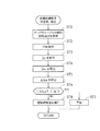
- step ST1 the instantaneous rotation speed of the turbocharger 40 is acquired.
- the signal (sine wave or rectangular wave) output from the turbo rotation speed sensor 104 is frequency-converted by the F / V converter 110, thereby acquiring the instantaneous rotation speed of the turbocharger 40.
- step ST2 the frequency F4 calculated by the equation (5) is acquired.
- step ST3 the calculates the total fuel injection amount Q all using the total fuel injection amount calculation map of FIG. 7. Specifically, information on the instantaneous rotational speed of the turbocharger 40 is transmitted to the engine ECU 100, and based on F4 data of the frequency analysis data, the total fuel injection amount Q all is calculated using the total fuel injection amount calculation map. Is calculated.
- step ST4 each injector 52 under the assumption that fuel is equally injected into each of the cylinders # 1 to # 4 based on the total fuel injection amount Q all by the following equation (6). , 52,..., Q ave is calculated.
- step ST5 a fuel injection amount deviation amount ⁇ Q tgt is calculated.
- the engine ECU 100 calculates the target injection amount Q tgt as the fuel injection amount from the injectors 52, 52,... According to the operation amount of the output operation member 101.
- the difference amount ⁇ Q tgt between the two is calculated by subtracting the target injection amount Q tgt from the average fuel injection amount Q ave calculated in the equation (6) (equation (7)).
- step ST6 it is determined whether or not the absolute value of the deviation amount ⁇ Q tgt exceeds a predetermined threshold value Q th .
- This threshold value Q th is a value for determining whether or not there is an abnormality in the fuel supply device 50, such as when the fuel injection amount from the injector 52 is too small, and is set in advance through experiments and simulations.
- step ST6 If the absolute value of the deviation amount ⁇ Q tgt exceeds the threshold value Q th and a YES determination is made in step ST6, the process proceeds to step ST7, where misfiring occurs due to an abnormality in the fuel supply device 50 or a significant change in fuel properties. Alerts the user that it has occurred. For example, a warning is displayed on an operation panel (not shown) or a voice warning is issued. Further, the abnormality occurrence information is written in the RAM of the engine ECU 100.
- step ST6 the process proceeds to step ST8 to correct the fuel injection amount of each injector 52, 52,. Do. That is, when the deviation amount ⁇ Q tgt is a positive value, correction is performed to reduce the fuel injection amounts from the injectors 52, 52,... In each of the cylinders # 1 to # 4 by the deviation amount ⁇ Q tgt . On the other hand, when the deviation amount ⁇ Q tgt is a negative value, correction is performed to increase the fuel injection amounts from the injectors 52, 52,... In each of the cylinders # 1 to # 4 by the deviation amount ⁇ Q tgt .
- the valve opening time of the injectors 52, 52,... Is changed when the increase correction is performed, the valve opening time is lengthened according to the increase correction amount and the decrease correction is performed). The valve opening time is shortened according to the amount of reduction correction).
- the total fuel injection amount Q all becomes the total fuel injection amount for obtaining the output required for the engine 1 (the target total fuel injection amount obtained by multiplying the target injection amount Q tgt by the number of cylinders). It will converge.
- steps ST4 to ST8 are performed by the fuel supply amount correction unit referred to in the present invention (supplied to each cylinder during one cycle of the multi-cylinder internal combustion engine). Divide the total fuel supply amount by the number of cylinders to obtain the average fuel supply amount, and supply fuel to each cylinder by the difference between the target fuel supply amount and the average fuel supply amount in each cylinder determined according to the required output Equivalent to the operation of correcting the amount).
- Such a diagnosis operation and a correction operation for the total fuel injection amount Q all are preferably performed when the engine load reaches the upper limit value. This is because when the total fuel injection amount Q all is corrected in the partial load region, the speed control performance of the engine 1 may be deteriorated.
- the above is the diagnosis operation and correction operation of the total fuel injection amount.
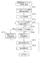
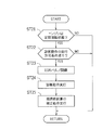
- step ST11 the instantaneous rotation speed of the turbocharger 40 is acquired as in step ST1 of the flowchart shown in FIG.
- step ST12 the frequencies F1 and F2 calculated by the above equations (2) and (3) are obtained.
- step ST13 After acquiring the frequencies F1 and F2, the process proceeds to step ST13, where it is determined whether or not the fuel injection amounts of the injectors 52, 52,. Specifically, as this determination operation, it is determined whether or not the intensities of the frequencies F1 and F2 are both substantially “0”. As described above, when the fuel injection amounts of all of the injectors 52, 52,... Are the same, the frequencies F1 and F2 are both substantially “0” (see FIGS. 2 and 3). By recognizing these intensities, it is possible to determine whether or not the fuel injection amounts of the injectors 52, 52,.
- the frequency characteristics of the frequencies F1 and F2 are expanded into a Fourier series, and it is determined whether or not the operating point plotted on the complex plane is located at the origin on the complex plane. Also good. As described above, when the fuel injection amounts of all the injectors 52, 52,... Are substantially the same, the operating point is located at the origin on the complex plane. It is possible to determine whether or not the fuel injection amounts of the injectors 52, 52,... Are substantially the same as each other.
- step ST13 When the fuel injection amounts of the injectors 52, 52,... Are the same as each other and YES is determined in step ST13, the correction operation for eliminating the variation in the fuel injection amounts is not necessary, and the process is returned as it is. .
- step ST13 the process proceeds to step ST14 to compare the intensities of the frequencies F1, F2. Specifically, it is determined whether or not the intensity of the frequency F1 is higher than the intensity of the frequency F2. This determination is made as follows: “The fuel injection amount in only one cylinder is different from the fuel injection amount in each of the other three cylinders, or the fuel injection amount in each of the two cylinders in which the combustion stroke is continued is in each of the other two cylinders. Or “the fuel injection amount in each of the two cylinders where the combustion stroke is not continuous is different from the fuel injection amount in each of the other two cylinders”.
- the intensity of frequency F1 is higher than the intensity of frequency F2, and if YES is determined in step ST14, the fuel injection amount in only one cylinder is different from the fuel injection amount in each of the other three cylinders. It can be determined that the fuel injection amount in each of the two cylinders that are different or the combustion strokes are continuous is different from the fuel injection amount in each of the other two cylinders.
- the intensity of the frequency F2 is higher than the intensity of the frequency F1
- NO is determined in step ST14
- the fuel injection amount in each of the two cylinders in which the combustion stroke is not continuous is the same in each of the other two cylinders. It can be judged that the situation is different from the fuel injection amount.
- step ST14 If YES is determined in step ST14, the process proceeds to step ST15, and diagnosis of variations in the fuel injection amounts of the injectors 52, 52,. A specific method of the diagnosis method 1 will be described later. On the other hand, if NO is determined in step ST14, the process proceeds to step ST16, and diagnosis of variations in the fuel injection amounts of the injectors 52, 52,. A specific method of the diagnostic method 2 will also be described later.
- an operation base vector at the time of changing the fuel injection amount in each of the cylinders # 1 to # 4 with respect to the engine speed is obtained in advance by experiment or analysis.
- This operating base vector is obtained by changing the fuel injection amount of the injector 52 in one cylinder by a preset unit injection amount, and the vector angle and vector corresponding to the cylinder and the change amount of the fuel injection amount.
- the length is represented on the complex plane.
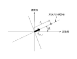
- FIG. 10 shows the operation base vector v ⁇ ref # i when the fuel injection amount in the second cylinder # 2 is reduced by the unit injection amount.
- this operation base vector v ⁇ ref # i is a vector connecting the origin and the operation point on the polar coordinates when the fuel injection amount in the i-th cylinder (for example, the second cylinder # 2 in FIG. 10) is changed. It is organized per unit injection amount. For this reason, when the actual operating point is the position of “ ⁇ ” in FIG. 10, the vector obtained by multiplying the length of the operating base vector v ⁇ ref # i by L i becomes the operating point “ ⁇ ”. This is the vector that appears (the vector from the origin to the operating point “ ⁇ ”). That is, the fuel injection amount is shifted in the i-th cylinder by the fuel injection amount Li times the unit injection amount.
- the intensity of the frequency F1 is higher than the intensity of the frequency F2, and “the fuel injection amount in only one cylinder is different from the fuel injection amounts in the other three cylinders.
- the frequency F1 component is extracted, and an actually measured operating point (hereinafter also referred to as an actually measured operating point) is plotted on a complex plane.
- FIG. 11 shows a case where the actually measured operating points are plotted on the coordinates ( ⁇ act , L act ).
- the scalar quantity of the two-way vector V ⁇ act # i , V ⁇ act # j obtained by this decomposition is obtained, and the deviation of the fuel injection quantity in each cylinder i, j is obtained using the correlation equation obtained in advance.
- the amounts (deviations from the fuel injection amounts in the other cylinders) ⁇ Q i and ⁇ Q j are calculated.
- the following equation (9) exists between the operating point vector V ⁇ act # i , the operating base vector v ⁇ ref # i , and the scalar quantity L i for the cylinder i.
- the scalar quantity L i can be calculated from 9).
- ⁇ ref # i is the angle of the operating point vector V ⁇ act # i from the coordinate axis of the real part
- ⁇ ref # j is the angle of the operating point vector V ⁇ act # j from the coordinate axis of the real part.
- the coefficient a in the equations (12) and (13) is obtained in advance by experiment or simulation, and defines the relationship between the scalar amount L and the actual fuel injection amount deviation amount ⁇ Q as shown in FIG. 12, for example. To do.
- the deviation amounts may be extracted using a deviation amount calculation map created in advance.
- the coefficient a may be the same value for all the cylinders or may be set for each cylinder according to experiments or simulations.
- the intensity of the frequency F2 is higher than the intensity of the frequency F1. It is executed when it is determined that the situation is different.
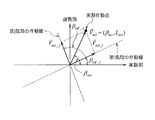
- FIG. 13 shows a case where the operating point is plotted at coordinates ( ⁇ act , L act ).
- the fuel injection amount in any of the cylinders is increased or decreased (the vector indicated by the one-dot chain line V ⁇ 1 in FIG. 13 is the case where the i-th cylinder (second cylinder # 2) is decreased, and the one-dot chain line V ⁇ The vector indicated by 2 is obtained when the i-th cylinder (second cylinder # 2) is increased), and the F1 component is set to “0”. That is, the operating point is positioned at the origin on the complex plane. In this case, the deviation amounts of the fuel injection amounts in the two cylinders coincide.
- the amount of deviation of the two cylinders (the amount of fuel injection in the state where the fuel injection amounts in the two cylinders are matched). And the amount of deviation from the fuel injection amount in each of the other two cylinders). Then, the deviation amount of the fuel injection amount in each cylinder is calculated in consideration of the fuel injection amount correction value obtained in advance.
- the characteristic with respect to the change amount of the fuel injection amount is not a straight line (see FIG. 14)
- the actually measured operating point during engine operation is plotted on the complex plane of F1.
- the operating point is located on the operating line of each cylinder obtained in FIG. This is because, as shown in FIG. 13, when the fuel injection amounts of the cylinders that are in antiphase with each other are shifted, there is no change in the ⁇ direction. If the deviation amount of the fuel injection amount in the i-th cylinder and the deviation amount of the fuel injection amount in the j-th cylinder are the same amount, the operating point on the complex plane of F1 does not move from the origin. Become.
- the fuel injection amount changing operation when the operating point on the complex plane of F1 is different from the origin, the fuel injection amount supplied to any of the i-th cylinder and the j-th cylinder is adjusted. To bring the operating point to the origin. If the fuel injection amount in the i-th cylinder is adjusted, the corrected injection amount ⁇ Q i # cor when the operating point reaches the origin is stored. At this time, the deviation amounts of the fuel injection amounts in the i-th cylinder and the j-th cylinder, which are the target cylinders, are equal.
- the operating point is plotted on the complex plane of F2, and the coordinates ( ⁇ ij # act , L ij # act ) and the deviation amount of the fuel injection amount obtained in advance are plotted.
- the deviation amount ⁇ Q ij of the fuel injection amount in the i-th cylinder and the j-th cylinder is calculated from the characteristic data.
- the deviation amount ⁇ Q i of the fuel injection amount in the i-th cylinder can be calculated by the following equation (14). Further, the deviation amount ⁇ Q j of the fuel injection amount in the j-th cylinder can be calculated by the following equation (15).
- the fuel injection amounts Q i # cor and Q j # cor in each cylinder for eliminating the variation in the fuel injection amount in each cylinder are calculated by the following equations (16) and (17).
- Expression (16) is an expression for obtaining the fuel injection quantity Q i # cor for eliminating the deviation in the fuel injection quantity in the i-th cylinder
- Expression (17) eliminates the deviation in the fuel injection quantity in the j-th cylinder. This is an equation for obtaining the fuel injection amount Q j # cor for the purpose.
- step ST18 fuel injection is executed by controlling the valve opening time of the injector 52 so that the calculated fuel injection amount is obtained.
- the pistons are in the same phase. It can be diagnosed that there is a divergence in the fuel injection amount of any of the two cylinders (for example, the first cylinder # 1 and the fourth cylinder # 4) that reciprocate and do not have a continuous combustion stroke. For this reason, in actual fuel injection, fuel injection to one cylinder is performed with the calculated fuel injection amount. If variation in the fuel injection amount is not eliminated by this, fuel injection to the one cylinder is performed. Returning, fuel injection at the calculated fuel injection amount is performed on the other cylinder. This is the same when the fuel injection amount in each of the two cylinders is different from the fuel injection amount in each of the other two cylinders.
- step ST17 and ST18 are performed by the variation elimination correcting unit referred to in the present invention (so as to eliminate the variation in the combustion state of the fuel between the cylinders). And the operation of correcting the control amount for changing the combustion state of the fuel for each cylinder).
- the fuel injection amount is controlled by the fuel pressure and the energization time to the solenoid of the injector 52, etc., so the deviation of the fuel injection amount is expressed by the following equations (18) and (19). You may make it cancel.
- ⁇ is an energization time to the injector 52 (corresponding to a valve opening time). That is, ⁇ i is the current (before correction) valve opening time for the i-th cylinder injector 52, and ⁇ j is the current (before correction) valve opening time for the j-th cylinder injector 52.
- ⁇ i # cor is a correction amount of the valve opening time of the injector 52 in the i-th cylinder
- ⁇ j # cor is a correction amount of the valve opening time of the injector 52 in the j-th cylinder.
- ⁇ i # cor is the valve opening time after correction of the injector 52 in the i-th cylinder
- ⁇ j # cor is the valve opening time after correction of the injector 52 in the j-th cylinder.
- the fuel injection in each of the cylinders # 1 to # 4 is performed by performing the correction operation of the total fuel injection amount and the operation of eliminating the variation in the fuel injection amount of each injector 52, 52,. It becomes possible to control the amount appropriately. That is, the fuel injection amounts of the injectors 52, 52,... Of the cylinders # 1 to # 4 can be matched with the target injection amount Q tgt without variation. For this reason, it is possible to suppress reduction in engine output, reduce rotational fluctuation, improve exhaust emission, and the like.
- Modification 1 defines the execution permission conditions for the above-described total fuel injection amount diagnosis operation and fuel injection amount variation diagnosis operation. That is, the above-described diagnostic operations are executed only when the execution permission condition is satisfied.
- the present invention utilizes the fact that there is a correlation between the fuel injection amount for each cylinder # 1 to # 4, the enthalpy of the exhaust gas, and the amount of fluctuation in the rotational speed of the turbocharger 40. For this reason, under operating conditions where conditions that impair these relationships may occur, there is a possibility that a diagnostic operation may be misdiagnosed. Therefore, in order to ensure the reliability of this diagnostic operation, the execution of each diagnostic operation is permitted. It is preferable to limit the operating conditions. This modification prescribes this operating condition.
- the execution permission conditions for each diagnostic operation are defined by the engine speed, engine load, cooling water temperature, intake pressure, exhaust pressure, intake temperature, and atmospheric pressure.
- the engine rotation speed is calculated based on an output signal from the engine rotation speed sensor 102.
- the engine load is obtained from an output signal from the load state detection member 103.
- the coolant temperature is obtained from an output signal from the coolant temperature sensor 105.
- the intake pressure is obtained from an output signal from the intake pressure sensor 106.
- the exhaust pressure is obtained from an output signal from the exhaust pressure sensor 107.
- the intake air temperature is obtained from an output signal from the intake air temperature sensor 108.
- the atmospheric pressure is obtained from an output signal from the atmospheric pressure sensor 109.
- the conditions for permitting execution of each of the diagnostic operations at the engine rotation speed are satisfied when the engine rotation speed is equal to or higher than a predetermined lower limit speed and is in steady rotation (for example, when the engine rotation speed does not change for 1 sec). To do. This is because if the engine speed changes during the diagnostic operation, the fuel injection amount is likely to change, and the correlation (the fuel injection amount for each cylinder # 1 to # 4 and the turbocharger 40 In view of the fact that the correlation between the rotational speed fluctuation amount) changes and it becomes difficult to ensure the reliability of the diagnostic operation, the execution of each diagnostic operation is not permitted.
- the lower limit speed of the engine rotation speed is set based on experiments or simulations.
- the execution permission condition for each of the diagnostic operations at the cooling water temperature is satisfied when the cooling water temperature is equal to or higher than a predetermined temperature (the warm-up completion temperature of the engine 1). This is because when the cooling water temperature is low, heat loss in the cylinder increases, and the correlation between the fuel injection amount, the enthalpy of the exhaust gas, and the fluctuation amount of the rotational speed of the turbocharger 40 changes. Therefore, the execution permission condition is established when the cooling water temperature is equal to or higher than the predetermined temperature. In addition, when the cooling water temperature is low, the lubricating oil temperature is also low, the friction loss around the bearing of the turbocharger 40 becomes large, and the correlation changes, making it difficult to ensure the reliability of the diagnostic operation. Thus, the execution of each diagnostic operation is not permitted.
- a predetermined temperature the warm-up completion temperature of the engine 1).
- the execution permission condition for each diagnosis operation at the intake pressure is satisfied when the intake pressure is equal to or lower than a predetermined pressure loss limit value. This is because the execution of each diagnosis operation is not permitted in view of the fact that it is difficult to ensure the reliability of the diagnosis operation when the intake pressure decreases due to the clogging of the air filter 23 or the like. is there.
- the pressure loss limit value of the intake pressure is set based on experiments or simulations.
- the execution permission condition for each diagnostic operation at the exhaust pressure is satisfied when the exhaust pressure is equal to or lower than a predetermined limit value. This is because when the amount of soot accumulation in the exhaust purification device 33 (particularly the DPF) increases, the pressure on the outlet side of the turbine wheel 42 changes, making it difficult to ensure the reliability of the diagnostic operation. The operation is not permitted to be executed.
- the exhaust gas limit value is set based on experiments or simulations.
- the conditions for permitting execution of each diagnostic operation at the intake air temperature are satisfied when the intake air temperature is equivalent to normal temperature (for example, about 20 ° C. to 25 ° C.).
- the conditions for permitting execution of each of the diagnostic operations at atmospheric pressure are satisfied when the atmospheric pressure is equal to or lower than a predetermined pressure (for example, 1000 mb).
- the condition for permitting execution of the diagnosis operation for the total fuel injection amount is different from the condition for permitting execution of the diagnosis operation for variation in the fuel injection amount.
- the execution permission condition for the diagnosis operation of the total fuel injection amount is satisfied when the engine load is equal to or higher than a predetermined lower limit load and is steady (for example, when it does not change for 1 sec).
- the execution permission condition for the operation of diagnosing variation in the fuel injection amount is satisfied when the engine load is a predetermined limit load and is steady (for example, when it does not change for 1 sec).
- Modification 2 Next, Modification 2 will be described.
- the permission and prohibition of the above-described diagnosis operation for the total fuel injection amount and the diagnosis operation for variation in the fuel injection amount are switched according to the operating state of the EGR device 60.
- the EGR rate being “0” is defined as a condition for permitting execution of the diagnostic operation for the total fuel injection amount. That is, the diagnosis operation of the total fuel injection amount is permitted only during a period in which the valve opening command signal output from the engine ECU 100 to the EGR valve 62 is a signal that is “opening 0”.
- the EGR rate is set to “0” as a condition for permitting execution of the diagnosis operation (exhaust gas recirculation by the EGR device 60 is stopped). Under these conditions, it is preferable to diagnose the variation in the combustion state of the fuel between the cylinders # 1 to # 4 (variation in the fuel injection amount) from the viewpoint of sufficiently ensuring reliability.
- FIG. 17 is a flowchart showing a control procedure in this modification. This flowchart is also repeated every predetermined time after the start switch of the engine 1 is turned on.
- step ST21 it is determined whether or not the engine 1 is in a steady operation state.
- the steady operation state here means a state in which the control operation (start mode) at the start of operation of the engine 1 or the control operation (stop mode) at the time of operation stop is not performed.
- step ST21 If the engine 1 is not in a steady operation state and NO is determined in step ST21, the process returns directly without executing the diagnostic operation.
- step ST21 if the engine 1 is in a steady operation state and YES is determined in step ST21, the process proceeds to step ST22, and whether or not the condition for permitting execution of the diagnostic operation described above (see the first modification) is satisfied. Determine. If the condition for permitting execution of the diagnostic operation is not satisfied and the determination is NO in step ST22, the routine returns directly without executing the diagnostic operation.
- step ST22 if the condition for permitting execution of the diagnostic operation is established and YES is determined in step ST22, the process proceeds to step ST23, and the EGR valve 62 is closed. That is, the valve opening command signal of “opening 0” is output from the engine ECU 100 to the EGR valve 62, and the EGR valve 62 is closed.
- the operation of closing the EGR valve 62 may be performed every time the execution permission condition for the diagnosis operation is satisfied, or when the execution permission condition is satisfied after a predetermined time has elapsed since the previous diagnosis operation. You may make it perform.
- step ST24 the above-described diagnosis operations (diagnosis operation for the total fuel injection amount and diagnosis operation for variation in the fuel injection amount) are performed. Since this diagnosis operation has been described in the above embodiment, a description thereof is omitted here. As described above, when the operation for diagnosing the total fuel injection amount is performed only when the engine load reaches the upper limit value, when the operation of the engine 1 is in the partial load region, this step ST24 Only the operation of diagnosing variation in the fuel injection amount is executed.
- step ST25 a fuel injection amount correction operation (a correction operation for the total fuel injection amount and a correction operation for eliminating variations in the fuel injection amount) according to the result of the diagnosis is executed. Since the fuel injection amount correcting operation has been described in the above embodiment, the description thereof is omitted here.
- the EGR rate is defined as “0” as a condition for permitting execution of the diagnostic operation. For this reason, it is possible to sufficiently ensure the reliability of the diagnostic operation, and it is also possible to appropriately correct the fuel injection amount performed according to the diagnostic result of the diagnostic operation.
- an EGR rate may be calculated and the fuel injection amount may be corrected according to the EGR rate. That is, the EGR rate is calculated using the exhaust pressure, the intake air temperature, the EGR gas temperature, the opening degree of the EGR valve 62, and the like as parameters. Then, the relationship between the EGR rate and the correction amount of the fuel injection amount is grasped in advance by experiment or simulation and mapped, and the fuel injection amount is corrected by applying the calculated EGR rate to this map. In this case, it is possible to appropriately correct the fuel injection amount regardless of the operating state of the engine 1 (even if the exhaust gas is recirculated to the intake system 20).
- Modification 3 Next, Modification 3 will be described. This modification considers the amount of exhaust gas passing through the wastegate valve 72 and the variable displacement mechanism for the turbocharger 40 having the wastegate valve 72 and the VGT (Variable Geometry Turbo) having the variable displacement mechanism. Thus, the correction amount of the fuel injection amount is obtained. Since the configuration of the variable capacity mechanism is known, the description thereof is omitted here.
- the exhaust gas amount G tur passing through the turbine wheel 42 of the turbocharger 40 can be calculated by the following equation (20).
- G exh is the total amount of exhaust gas
- G WG is the waste gate valve.
- G air is the intake air amount
- G fuel is the fuel injection amount.
- the exhaust gas amount G tur passing through the turbine wheel 42 can be calculated. It is.
- FIG. Schott Control valve 72
- the flow path area A out on the turbine wheel 42 outlet side can be calculated by the following equation (21).
- a tur is the channel area on the inlet side of the turbine wheel 42
- a WG is the channel area according to the opening degree of the wastegate valve 72.
- T DOC # in is the exhaust gas temperature at the inlet side of the exhaust purification device 33 downstream of the turbine wheel 42
- P DOC # in is the exhaust gas pressure at the inlet side of the exhaust purification device 33
- T exh is the exhaust gas at the inlet side of the turbine wheel 42.
- the gas temperature, P exh is the exhaust gas pressure on the turbine wheel 42 inlet side.
- R is a gas constant and ⁇ is a specific heat ratio.
- a out When the flow area A out when the input heat quantity is changed in advance under the condition of constant engine speed is calculated and plotted on the coordinate axis as shown in FIG. 20, the flow area in the operation region where the wastegate valve 72 is not opened.
- a out is a constant value, and a characteristic that the flow path area A out increases as the opening degree of the waste gate valve 72 increases as the fuel injection amount increases is obtained.
- a portion where the flow passage area A out is constant is regarded as an equivalent turbine passage area A tur
- a variable portion is regarded as an equivalent waste gate passage area A WG .
- the turbine passage flow rate G tur can be calculated from the ratio of the flow passage areas of the two as shown in the following equation (23).
- the correction value Q cor # WG of the deviation amount of the fuel injection amount can be calculated by the following equation (24), and this correction value is added to the correction amount of the fuel injection amount described above.
- ⁇ is a conversion coefficient obtained in advance by experiment or simulation.
- the fuel injection amount shifts in the same manner as described above according to the opening of the nozzle vane of the variable displacement mechanism (the opening of the nozzle vane that changes the exhaust gas passage area). It is possible to calculate an amount correction value.
- Modification 4 Next, Modification 4 will be described. This modification is a case where a two-stage turbocharger is provided as the turbocharger 40.
- FIG. 21 is a diagram showing a schematic configuration around the turbocharger 40 of the engine 1 according to this modification.
- the turbocharger 40 includes a high-pressure stage turbocharger 40a and a low-pressure stage turbocharger 40b.
- the high-pressure stage turbocharger 40a is disposed relatively downstream in the intake pipe 21 (downstream side of the low-pressure stage compressor wheel 41b of the low-pressure stage turbocharger 40b) and supercharges intake air, and an exhaust pipe 31 is provided on the relatively upstream side (upstream side of the low-pressure stage turbine wheel 42b of the low-pressure stage turbocharger 40b) and rotated by the fluid energy of the exhaust gas.
- the high-pressure stage compressor wheel 41a and the high-pressure stage turbine wheel 42a are connected by a rotating shaft 43a.
- the low-pressure stage turbocharger 40b is disposed on the relatively upstream side of the intake pipe 21 (upstream side of the high-pressure stage compressor wheel 41a of the high-pressure stage turbocharger 40a), and supercharges intake air.
- the exhaust pipe 31 includes a low-pressure stage turbine wheel 42b that is disposed relatively downstream (downstream side of the high-pressure stage turbine wheel 42a of the high-pressure stage turbocharger 40a) and rotates by the fluid energy of the exhaust gas.
- These low-pressure stage compressor wheel 41b and low-pressure stage turbine wheel 42b are connected by a rotating shaft 43b.
- the present invention uses a phenomenon in which the rotational speed of the turbocharger 40 varies due to energy pulsation during exhaust blowdown for each cylinder. For this reason, it is preferable to perform the diagnosis operation in accordance with the rotational speed of the high-pressure stage turbocharger 40a that is greatly affected by the energy pulsation and in which the fluctuation of the rotational speed appears.
- the turbo rotational speed sensor 104 is arranged to face the blades of the high-pressure stage compressor wheel 41a of the high-pressure stage turbocharger 40a.
- This configuration is the signal according to the rotational speed of the exhaust turbine supercharger for a multi-cylinder internal combustion engine provided with a plurality of exhaust turbine superchargers arranged in series with respect to the gas flow.
- a rotation speed detecting means for outputting is provided in the vicinity of the high-pressure side exhaust turbine supercharger and outputs a signal corresponding to the rotational speed of the high-pressure side exhaust turbine supercharger.
- turbo rotation speed sensor 104 By adopting such an arrangement form of the turbo rotation speed sensor 104, it is possible to sufficiently ensure the reliability of the diagnostic operation even in the engine 1 including the two-stage turbocharger.
- the present invention is not limited to this, and can be applied to various multi-cylinder internal combustion engines such as gasoline engines and gas engines.
- the present invention is also applied to a multi-cylinder internal combustion engine that includes a fuel reforming cylinder and a plurality of output cylinders, and supplies the fuel reformed in the fuel reforming cylinders to each output cylinder to obtain an output. Is possible.
- conditions for permitting execution of the diagnostic operation are given to the respective state quantities of the engine speed, the engine load, the cooling water temperature, the intake pressure, the exhaust pressure, the intake air temperature, and the atmospheric pressure.
- the diagnostic operation is permitted only when the amount satisfies the execution permission condition.
- the present invention is not limited to this, and an execution permission condition for the diagnostic operation is given to one of the state quantities or a plurality selected from the state quantities, and the state quantity satisfies the execution permission condition.
- the diagnosis operation may be permitted only in the case of
- the diagnosis of the variation in the combustion state of the fuel in each of the cylinders # 1 to # 4 the diagnosis of the variation in the fuel injection amount from each of the injectors 52, 52,. And explained.
- the present invention is not limited to this, and can also be used for diagnosing variations in fuel properties and combustion temperature variations in the respective cylinders # 1 to # 4.
- a diagnostic operation is performed during the operation of the engine 1, and a fuel injection amount correction operation is performed according to the diagnosis result during the operation.
- the present invention is not limited to this, and a technical idea is that a diagnostic operation is performed after the operation of the engine 1 is completed.
- the rotational speed information of the engine 1 and the rotational speed information of the turbocharger 40 are acquired and stored in a RAM or the like, and stored after the operation of the engine 1 is completed.
- the diagnosis of the total fuel injection amount and the variation of the fuel injection amount are performed from each rotational speed information.
- the turbo rotational speed sensor 104 is arranged to face the compressor wheel 41 to detect the rotational speed of the turbocharger 40.
- the present invention is not limited to this, and the turbo rotation speed sensor 104 is disposed opposite to the turbine wheel 42 (in this case, high heat resistance is required for the turbo rotation speed sensor 104), or opposed to the rotation shaft 43. It is good also as a structure which detects the rotational speed of the turbocharger 40 by arrange
- the frequency characteristic is expanded into a Fourier series, the characteristic is plotted on a complex plane to obtain an operating point, and a complex in a vector from the origin on the complex plane to the operating point is obtained.
- a cylinder whose fuel combustion state is different from the other cylinders is identified based on the angle formed with the coordinate axis of the plane, and a state quantity related to fuel combustion in the identified cylinder based on the vector length.
- the deviation from the state quantity in other cylinders are specified.
- the present invention is applicable to a device for diagnosing the combustion state of fuel in each cylinder in an engine equipped with a turbocharger, and a control device for controlling the engine according to the result of the diagnosis.
Landscapes
- Engineering & Computer Science (AREA)
- Chemical & Material Sciences (AREA)
- Combustion & Propulsion (AREA)
- Mechanical Engineering (AREA)
- General Engineering & Computer Science (AREA)
- Computer Hardware Design (AREA)
- Microelectronics & Electronic Packaging (AREA)
- Combined Controls Of Internal Combustion Engines (AREA)
- Electrical Control Of Air Or Fuel Supplied To Internal-Combustion Engine (AREA)
- Output Control And Ontrol Of Special Type Engine (AREA)
Abstract
Dispositif de diagnostic d'un moteur à combustion interne, le dispositif diagnostiquant des états de combustion de carburant dans chaque cylindre d'un moteur à combustion interne à cylindres multiples équipé d'un compresseur de suralimentation de turbine d'échappement, le dispositif étant pourvu : d'un moyen de détection de vitesse qui délivre un signal correspondant à la vitesse du compresseur de suralimentation de turbine d'échappement ou un signal corrélé à une fluctuation de la vitesse du compresseur de suralimentation de turbine d'échappement ; et d'une unité de diagnostic d'état de combustion qui diagnostique une variation d'états de combustion de carburant parmi les cylindres par une analyse de fréquence, à l'aide d'une transformée de Fourier rapide, des caractéristiques de fréquence du signal sorti par le moyen de détection de vitesse.
Priority Applications (3)
| Application Number | Priority Date | Filing Date | Title |
|---|---|---|---|
| US16/462,480 US20200063678A1 (en) | 2016-11-25 | 2017-11-01 | Diagnosis device and diagnosis method for internal combustion engine, and control device and control method for internal combustion engine |
| CN201780070042.4A CN109983215A (zh) | 2016-11-25 | 2017-11-01 | 内燃机的诊断装置和诊断方法以及内燃机的控制装置和控制方法 |
| EP17873462.0A EP3546733A4 (fr) | 2016-11-25 | 2017-11-01 | Dispositif et procédé de diagnostic de moteur à combustion interne, et dispositif et procédé de commande de moteur à combustion interne |
Applications Claiming Priority (2)
| Application Number | Priority Date | Filing Date | Title |
|---|---|---|---|
| JP2016-228735 | 2016-11-25 | ||
| JP2016228735A JP6669637B2 (ja) | 2016-11-25 | 2016-11-25 | 内燃機関の診断装置および診断方法、並びに、内燃機関の制御装置および制御方法 |
Publications (1)
| Publication Number | Publication Date |
|---|---|
| WO2018096894A1 true WO2018096894A1 (fr) | 2018-05-31 |
Family
ID=62195458
Family Applications (1)
| Application Number | Title | Priority Date | Filing Date |
|---|---|---|---|
| PCT/JP2017/039567 Ceased WO2018096894A1 (fr) | 2016-11-25 | 2017-11-01 | Dispositif et procédé de diagnostic de moteur à combustion interne, et dispositif et procédé de commande de moteur à combustion interne |
Country Status (5)
| Country | Link |
|---|---|
| US (1) | US20200063678A1 (fr) |
| EP (1) | EP3546733A4 (fr) |
| JP (1) | JP6669637B2 (fr) |
| CN (1) | CN109983215A (fr) |
| WO (1) | WO2018096894A1 (fr) |
Cited By (12)
| Publication number | Priority date | Publication date | Assignee | Title |
|---|---|---|---|---|
| EP3524805A4 (fr) * | 2017-12-27 | 2019-09-18 | Mitsubishi Heavy Industries Engine & Turbocharger, Ltd. | Dispositif de détection d'anomalie de moteur |
| US11636870B2 (en) | 2020-08-20 | 2023-04-25 | Denso International America, Inc. | Smoking cessation systems and methods |
| US11760170B2 (en) | 2020-08-20 | 2023-09-19 | Denso International America, Inc. | Olfaction sensor preservation systems and methods |
| US11760169B2 (en) | 2020-08-20 | 2023-09-19 | Denso International America, Inc. | Particulate control systems and methods for olfaction sensors |
| US11813926B2 (en) | 2020-08-20 | 2023-11-14 | Denso International America, Inc. | Binding agent and olfaction sensor |
| US11828210B2 (en) | 2020-08-20 | 2023-11-28 | Denso International America, Inc. | Diagnostic systems and methods of vehicles using olfaction |
| US11881093B2 (en) | 2020-08-20 | 2024-01-23 | Denso International America, Inc. | Systems and methods for identifying smoking in vehicles |
| US11932080B2 (en) | 2020-08-20 | 2024-03-19 | Denso International America, Inc. | Diagnostic and recirculation control systems and methods |
| US12017506B2 (en) | 2020-08-20 | 2024-06-25 | Denso International America, Inc. | Passenger cabin air control systems and methods |
| US12251991B2 (en) | 2020-08-20 | 2025-03-18 | Denso International America, Inc. | Humidity control for olfaction sensors |
| US12269315B2 (en) | 2020-08-20 | 2025-04-08 | Denso International America, Inc. | Systems and methods for measuring and managing odor brought into rental vehicles |
| US12377711B2 (en) | 2020-08-20 | 2025-08-05 | Denso International America, Inc. | Vehicle feature control systems and methods based on smoking |
Families Citing this family (8)
| Publication number | Priority date | Publication date | Assignee | Title |
|---|---|---|---|---|
| CN113286940A (zh) * | 2019-01-15 | 2021-08-20 | 三菱重工发动机和增压器株式会社 | 发动机的运行状态判定装置、车辆、以及发动机的运行状态判定方法 |
| CN111237092A (zh) * | 2020-03-10 | 2020-06-05 | 中科环能(天津)动力科技有限公司 | 一种超低浓度瓦斯气体机燃烧系统及其控制方法 |
| CN111721538A (zh) * | 2020-06-29 | 2020-09-29 | 潍柴动力股份有限公司 | 发动机检测方法及装置 |
| CN112211737B (zh) * | 2020-10-14 | 2022-07-15 | 哈尔滨工程大学 | 一种高压共轨喷油器控制室处燃油稳态温升计算方法 |
| WO2022087546A1 (fr) * | 2020-10-22 | 2022-04-28 | Tula Technology, Inc. | Désactivation de cylindre de décélération et gestion de vitesse de rotation de turbocompresseur |
| CN113514250B (zh) * | 2021-06-25 | 2022-09-16 | 一汽解放汽车有限公司 | 喷油器诊断方法、装置、计算机设备和存储介质 |
| US11473446B1 (en) | 2021-09-20 | 2022-10-18 | Apexturbo Llc | Bearing cartridge assembly for a turbocharger |
| GB2627472B (en) * | 2023-02-23 | 2025-04-02 | Phinia Delphi Luxembourg Sarl | Method for detecting pre-ignition events in gaseous-fueled engines |
Citations (5)
| Publication number | Priority date | Publication date | Assignee | Title |
|---|---|---|---|---|
| JP2001065397A (ja) | 1999-08-24 | 2001-03-13 | Mazda Motor Corp | エンジンの燃料噴射制御装置 |
| JP2011052616A (ja) * | 2009-09-02 | 2011-03-17 | Isuzu Motors Ltd | 多気筒内燃機関の燃料噴射制御装置 |
| JP5770657B2 (ja) | 2012-03-01 | 2015-08-26 | ヤンマー株式会社 | エンジン |
| JP2015169191A (ja) * | 2014-03-11 | 2015-09-28 | 富士重工業株式会社 | 気筒間ばらつき異常検知装置 |
| JP2016031018A (ja) * | 2014-07-25 | 2016-03-07 | トヨタ自動車株式会社 | 内燃機関用制御装置 |
Family Cites Families (15)
| Publication number | Priority date | Publication date | Assignee | Title |
|---|---|---|---|---|
| US6021758A (en) * | 1997-11-26 | 2000-02-08 | Cummins Engine Company, Inc. | Method and apparatus for engine cylinder balancing using sensed engine speed |
| US6609375B2 (en) * | 2001-09-14 | 2003-08-26 | Honeywell International Inc. | Air cooling system for electric assisted turbocharger |
| DE102005057975A1 (de) * | 2005-12-05 | 2007-06-06 | Robert Bosch Gmbh | Verfahren zur zylinderindividuellen Steuerung der Kraftstoff- und/oder Luftmenge einer Brennkraftmaschine |
| DE102006027422B4 (de) * | 2006-06-13 | 2014-02-06 | Continental Automotive Gmbh | Verfahren und Vorrichtung zum Überwachen eines Abgasturboladers |
| JP4492664B2 (ja) * | 2007-09-28 | 2010-06-30 | 株式会社デンソー | 燃料供給量推定装置及び燃料圧送噴射システム |
| DE102008054215A1 (de) * | 2008-10-31 | 2010-05-06 | Bayerische Motoren Werke Aktiengesellschaft | Verfahren zur Vertrimmungsbestimmung einer Brennkraftmaschine mit zumindest zwei Brennkammern |
| US8091410B2 (en) * | 2009-09-29 | 2012-01-10 | Delphi Technologies, Inc. | Phase-based misfire detection in engine rotation frequency domain |
| JP5246284B2 (ja) * | 2011-03-02 | 2013-07-24 | トヨタ自動車株式会社 | 内燃機関の制御装置 |
| EP2565430B1 (fr) * | 2011-04-07 | 2018-02-21 | Toyota Jidosha Kabushiki Kaisha | Appareil de commande de moteur à combustion interne |
| AT513139B1 (de) * | 2012-08-17 | 2014-02-15 | Ge Jenbacher Gmbh & Co Og | Verfahren zum Betreiben einer Brennkraftmaschine |
| CN104583560B (zh) * | 2012-08-23 | 2017-04-26 | 丰田自动车株式会社 | 排气旁通阀的控制装置 |
| DE102012020490B3 (de) * | 2012-10-10 | 2014-03-13 | Mtu Friedrichshafen Gmbh | Verfahren zur Ausfallerkennung von Injektoren in einem Verbrennungsmotor, Motorsteuergerät und System zur Durchführung eines Verfahrens |
| DE102015102249B4 (de) * | 2015-02-17 | 2017-10-12 | Maridis GmbH | Verfahren und Vorrichtung zur Bestimmung der Leistungsverteilung einer Verbrennungskraftmaschine aus dem an der Kurbelwelle gemessenem Drehungleichförmigkeitsverlauf |
| US9964057B2 (en) * | 2015-10-19 | 2018-05-08 | General Electric Company | Method and system for adjusting engine cylinder operation |
| US9885305B2 (en) * | 2016-02-24 | 2018-02-06 | Ford Global Technologies, Llc | Method for reducing cylinder air-fuel ratio imbalance |
-
2016
- 2016-11-25 JP JP2016228735A patent/JP6669637B2/ja not_active Expired - Fee Related
-
2017
- 2017-11-01 CN CN201780070042.4A patent/CN109983215A/zh active Pending
- 2017-11-01 US US16/462,480 patent/US20200063678A1/en not_active Abandoned
- 2017-11-01 EP EP17873462.0A patent/EP3546733A4/fr not_active Withdrawn
- 2017-11-01 WO PCT/JP2017/039567 patent/WO2018096894A1/fr not_active Ceased
Patent Citations (5)
| Publication number | Priority date | Publication date | Assignee | Title |
|---|---|---|---|---|
| JP2001065397A (ja) | 1999-08-24 | 2001-03-13 | Mazda Motor Corp | エンジンの燃料噴射制御装置 |
| JP2011052616A (ja) * | 2009-09-02 | 2011-03-17 | Isuzu Motors Ltd | 多気筒内燃機関の燃料噴射制御装置 |
| JP5770657B2 (ja) | 2012-03-01 | 2015-08-26 | ヤンマー株式会社 | エンジン |
| JP2015169191A (ja) * | 2014-03-11 | 2015-09-28 | 富士重工業株式会社 | 気筒間ばらつき異常検知装置 |
| JP2016031018A (ja) * | 2014-07-25 | 2016-03-07 | トヨタ自動車株式会社 | 内燃機関用制御装置 |
Non-Patent Citations (1)
| Title |
|---|
| See also references of EP3546733A4 * |
Cited By (12)
| Publication number | Priority date | Publication date | Assignee | Title |
|---|---|---|---|---|
| EP3524805A4 (fr) * | 2017-12-27 | 2019-09-18 | Mitsubishi Heavy Industries Engine & Turbocharger, Ltd. | Dispositif de détection d'anomalie de moteur |
| US11636870B2 (en) | 2020-08-20 | 2023-04-25 | Denso International America, Inc. | Smoking cessation systems and methods |
| US11760170B2 (en) | 2020-08-20 | 2023-09-19 | Denso International America, Inc. | Olfaction sensor preservation systems and methods |
| US11760169B2 (en) | 2020-08-20 | 2023-09-19 | Denso International America, Inc. | Particulate control systems and methods for olfaction sensors |
| US11813926B2 (en) | 2020-08-20 | 2023-11-14 | Denso International America, Inc. | Binding agent and olfaction sensor |
| US11828210B2 (en) | 2020-08-20 | 2023-11-28 | Denso International America, Inc. | Diagnostic systems and methods of vehicles using olfaction |
| US11881093B2 (en) | 2020-08-20 | 2024-01-23 | Denso International America, Inc. | Systems and methods for identifying smoking in vehicles |
| US11932080B2 (en) | 2020-08-20 | 2024-03-19 | Denso International America, Inc. | Diagnostic and recirculation control systems and methods |
| US12017506B2 (en) | 2020-08-20 | 2024-06-25 | Denso International America, Inc. | Passenger cabin air control systems and methods |
| US12251991B2 (en) | 2020-08-20 | 2025-03-18 | Denso International America, Inc. | Humidity control for olfaction sensors |
| US12269315B2 (en) | 2020-08-20 | 2025-04-08 | Denso International America, Inc. | Systems and methods for measuring and managing odor brought into rental vehicles |
| US12377711B2 (en) | 2020-08-20 | 2025-08-05 | Denso International America, Inc. | Vehicle feature control systems and methods based on smoking |
Also Published As
| Publication number | Publication date |
|---|---|
| CN109983215A (zh) | 2019-07-05 |
| EP3546733A1 (fr) | 2019-10-02 |
| EP3546733A4 (fr) | 2019-12-04 |
| JP2018084207A (ja) | 2018-05-31 |
| JP6669637B2 (ja) | 2020-03-18 |
| US20200063678A1 (en) | 2020-02-27 |
Similar Documents
| Publication | Publication Date | Title |
|---|---|---|
| JP6669637B2 (ja) | 内燃機関の診断装置および診断方法、並びに、内燃機関の制御装置および制御方法 | |
| EP2715087B1 (fr) | Appareil à moteur suralimenté du type turbo-compound | |
| JP5277351B2 (ja) | 内燃機関の制御装置 | |
| US9228504B2 (en) | Diesel engine | |
| US20110093182A1 (en) | Estimating engine parameters based on dynamic pressure readings | |
| JP5187123B2 (ja) | 内燃機関の制御装置 | |
| US20160003133A1 (en) | Control device for internal combustion engine | |
| WO2010008961A2 (fr) | Diagnostic d’un sous-système de refroidissement d’un système de moteur en réponse à une pression dynamique détectée dans le sous-système | |
| CN105980688B (zh) | 带有涡轮增压器的发动机的异常检测装置 | |
| JP2008240576A (ja) | 過給システムの故障診断装置 | |
| JP5719257B2 (ja) | 過給機の制御装置 | |
| EP2211044B1 (fr) | Contrôleur EGR et procédé de contrôle EGR pour moteur à combustion interne | |
| JP6971349B2 (ja) | 内燃機関の過給圧制御装置 | |
| US10145297B2 (en) | Control device for engine equipped with turbo-supercharger | |
| JP2014020227A (ja) | ウェイストゲートバルブの状態推定装置 | |
| US12018623B2 (en) | Cam phasing control for thermal management | |
| US11428597B2 (en) | Method for diagnosing a supercharged internal combustion engine for leakage in a portion of the intake air line | |
| JP4455353B2 (ja) | 内燃機関の制御装置 | |
| JP2010168954A (ja) | 内燃機関の制御装置 | |
| JP6006078B2 (ja) | 内燃機関の制御装置 | |
| JP2015206307A (ja) | 内燃機関の制御装置 | |
| EP2354501A2 (fr) | Appareil de contrôle pour moteur à combustion interne | |
| US10890503B2 (en) | Position sensor malfunction determination apparatus | |
| JP4455668B2 (ja) | 内燃機関の制御装置 | |
| JP2009047010A (ja) | 内燃機関の制御装置 |
Legal Events
| Date | Code | Title | Description |
|---|---|---|---|
| 121 | Ep: the epo has been informed by wipo that ep was designated in this application |
Ref document number: 17873462 Country of ref document: EP Kind code of ref document: A1 |
|
| NENP | Non-entry into the national phase |
Ref country code: DE |
|
| ENP | Entry into the national phase |
Ref document number: 2017873462 Country of ref document: EP Effective date: 20190625 |