WO2018096907A1 - Structure d'amortisseur de changement de vitesse pour transmission - Google Patents
Structure d'amortisseur de changement de vitesse pour transmission Download PDFInfo
- Publication number
- WO2018096907A1 WO2018096907A1 PCT/JP2017/039756 JP2017039756W WO2018096907A1 WO 2018096907 A1 WO2018096907 A1 WO 2018096907A1 JP 2017039756 W JP2017039756 W JP 2017039756W WO 2018096907 A1 WO2018096907 A1 WO 2018096907A1
- Authority
- WO
- WIPO (PCT)
- Prior art keywords
- transmission member
- transmission
- shift
- fluid
- power transmitting
- Prior art date
- Legal status (The legal status is an assumption and is not a legal conclusion. Google has not performed a legal analysis and makes no representation as to the accuracy of the status listed.)
- Ceased
Links
Images


Classifications
-
- F—MECHANICAL ENGINEERING; LIGHTING; HEATING; WEAPONS; BLASTING
- F16—ENGINEERING ELEMENTS AND UNITS; GENERAL MEASURES FOR PRODUCING AND MAINTAINING EFFECTIVE FUNCTIONING OF MACHINES OR INSTALLATIONS; THERMAL INSULATION IN GENERAL
- F16F—SPRINGS; SHOCK-ABSORBERS; MEANS FOR DAMPING VIBRATION
- F16F15/00—Suppression of vibrations in systems; Means or arrangements for avoiding or reducing out-of-balance forces, e.g. due to motion
- F16F15/10—Suppression of vibrations in rotating systems by making use of members moving with the system
- F16F15/12—Suppression of vibrations in rotating systems by making use of members moving with the system using elastic members or friction-damping members, e.g. between a rotating shaft and a gyratory mass mounted thereon
- F16F15/131—Suppression of vibrations in rotating systems by making use of members moving with the system using elastic members or friction-damping members, e.g. between a rotating shaft and a gyratory mass mounted thereon the rotating system comprising two or more gyratory masses
- F16F15/133—Suppression of vibrations in rotating systems by making use of members moving with the system using elastic members or friction-damping members, e.g. between a rotating shaft and a gyratory mass mounted thereon the rotating system comprising two or more gyratory masses using springs as elastic members, e.g. metallic springs
- F16F15/134—Wound springs
-
- F—MECHANICAL ENGINEERING; LIGHTING; HEATING; WEAPONS; BLASTING
- F16—ENGINEERING ELEMENTS AND UNITS; GENERAL MEASURES FOR PRODUCING AND MAINTAINING EFFECTIVE FUNCTIONING OF MACHINES OR INSTALLATIONS; THERMAL INSULATION IN GENERAL
- F16F—SPRINGS; SHOCK-ABSORBERS; MEANS FOR DAMPING VIBRATION
- F16F15/00—Suppression of vibrations in systems; Means or arrangements for avoiding or reducing out-of-balance forces, e.g. due to motion
- F16F15/10—Suppression of vibrations in rotating systems by making use of members moving with the system
- F16F15/16—Suppression of vibrations in rotating systems by making use of members moving with the system using a fluid or pasty material
-
- F—MECHANICAL ENGINEERING; LIGHTING; HEATING; WEAPONS; BLASTING
- F16—ENGINEERING ELEMENTS AND UNITS; GENERAL MEASURES FOR PRODUCING AND MAINTAINING EFFECTIVE FUNCTIONING OF MACHINES OR INSTALLATIONS; THERMAL INSULATION IN GENERAL
- F16H—GEARING
- F16H61/00—Control functions within control units of change-speed- or reversing-gearings for conveying rotary motion ; Control of exclusively fluid gearing, friction gearing, gearings with endless flexible members or other particular types of gearing
- F16H61/26—Generation or transmission of movements for final actuating mechanisms
- F16H61/28—Generation or transmission of movements for final actuating mechanisms with at least one movement of the final actuating mechanism being caused by a non-mechanical force, e.g. power-assisted
- F16H61/32—Electric motors , actuators or related electrical control means therefor
-
- F—MECHANICAL ENGINEERING; LIGHTING; HEATING; WEAPONS; BLASTING
- F16—ENGINEERING ELEMENTS AND UNITS; GENERAL MEASURES FOR PRODUCING AND MAINTAINING EFFECTIVE FUNCTIONING OF MACHINES OR INSTALLATIONS; THERMAL INSULATION IN GENERAL
- F16H—GEARING
- F16H61/00—Control functions within control units of change-speed- or reversing-gearings for conveying rotary motion ; Control of exclusively fluid gearing, friction gearing, gearings with endless flexible members or other particular types of gearing
- F16H61/26—Generation or transmission of movements for final actuating mechanisms
- F16H61/34—Generation or transmission of movements for final actuating mechanisms comprising two mechanisms, one for the preselection movement, and one for the shifting movement
Definitions
- the present invention relates to a shift damper structure for a transmission.
- Patent Document 1 discloses a first transmission member that is rotated by transmission of an operation force of shift operation or selection operation by a manual operation or an actuator, and a position different from the first transmission member and relative to the first transmission member.
- a second transmission member that rotates, and a storage chamber formed between the first transmission member and the second transmission member are accommodated, and the power of the first transmission member is transmitted to the second transmission member to thereby transmit the first transmission member.
- the operating device of the transmission provided with the elastic member which permits rotation of 2 transmission members, and the operation part which carries out shift operation or selection operation by rotation of the said 2nd transmission member is disclosed.
- the impact from the actuating portion is absorbed by the elastic member, so that the transmission of the impact from the second transmission member to the first transmission member is suppressed.
- the elastic member that has absorbed the impact vibrates thereafter. This vibration may cause a deterioration in the feeling at the time of a manual shift operation or a select operation, a deterioration in power control of the actuator, a deterioration in controllability, and the like.
- An object of the present invention is to provide a shift damper structure for a transmission that efficiently prevents the vibration of an elastic member.
- the 1st transmission member which powers and rotates the operation force of shift operation or selection operation by a manual operation or an actuator, it is arranged in a different position from the 1st transmission member, and is relative to the 1st transmission member.
- a second transmission member rotatably provided, and a storage chamber formed between the first transmission member and the second transmission member, the power of the first transmission member being transmitted to the second transmission member
- the storage chamber may be formed by the first transmission member and the second transmission member.
- the selection mechanism restricts the outflow of fluid from the accommodation chamber and the inflow of fluid into the accommodation chamber when a rotation difference occurs between the first transmission member and the second transmission member.
- the restriction may be released when there is no rotational difference between the first transmission member and the second transmission member.
- the fluid storage portion in which the fluid is stored may be formed in the first transmission member, and the fluid stored in the fluid storage portion may be supplied to the storage chamber.
- the fluid filled in the storage chamber can regulate the operation of the elastic member. For this reason, it is possible to suppress efficiently the vibration of the elastic member which absorbed the impact from the operation part. By suppressing the vibration, it is possible to efficiently prevent the deterioration of the feeling at the time of the manual shift operation or the selection operation, the deterioration of the power control of the actuator, the deterioration of the controllability, and the like.
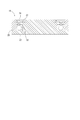
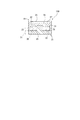
- FIG. 3 is a cross-sectional view taken along the line AA of FIG.
- FIG. 3 is a cross-sectional view taken along the line BB in FIG.
- FIG. 1 is an explanatory view conceptually showing the configuration of an operating device for a transmission.
- the operating device shown in the figure includes a shift and select shaft 1, an actuator 2 for select that performs a select operation by sliding the shift and select shaft 1 in the axial direction, and the shift and select shaft 1 about its axis. And a shift actuator 3 for performing a shift operation.
- the inner lever (actuating portion) 4 mounted on the shift and select shaft 1 slides together integrally with the shift and select shaft 1 in the axial direction, and a shift fork (not shown) select.
- the inner lever 4 is integrally rocked together with the shift-and-select shaft 1, and the shift fork selected as the shift target is slide-moved to shift the transmission 6.
- the actuator 2 for selection is constituted by a motor.
- the rotational power of the motor 2 is converted into the select operation force by the rack 1 a formed on the shift and select shaft 1.
- the shift actuator 3 is also constituted by a motor.
- the rotational power of the motor 3 is converted into a shift operation force by the gear 17 meshed with and supported by a gear 17 which is integrally splined to the shift-and-select shaft 1 and axially splined and slidably supported.
- the select operation is permitted.
- a damper device 18 is provided between the shift actuator 3 and the shift and select shaft 1. The shock from the transmission 6 is absorbed by the damper device 18 and transmission of the shock to the motor 3 is suppressed.
- FIG. 2 is a plan view showing the configuration of the damper device
- FIG. 3 is a cross-sectional view taken along the line AA of FIG. 2
- FIG. 4 is a cross-sectional view taken along the line BB of FIG.
- the damper device 18 is provided on the transmission shaft 14 in the illustrated example.
- the transmission shaft 14 is constituted by a first rotation shaft 14 a and a second rotation shaft 14 b which are coaxial with each other and separately formed.
- the damper device 18 as a transmission shift damper structure is formed in a disk shape, and is supported in a state in which the thickness direction is directed in the vertical direction.
- the damper device 18 is configured to rotate integrally with the first transmission member 19 that is integrally operated with the first rotation shaft 14 a and with the second rotation shaft 14 b so as to be rotatable relative to the first transmission member 19.
- the first transmission member 19 is accommodated in a second transmission member 21 stacked from the upper side, and a plurality of storage chambers 22 formed between the first transmission member 19 and the second transmission member 21 arranged at different positions from each other.
- a compression spring 23 is provided in a disk shape, and is supported in a state in which the thickness direction is directed in the vertical direction.
- the damper device 18 is configured to rotate integrally with the first transmission member 19 that is integrally operated with the first rotation shaft 14 a and with the second rotation shaft 14 b so as to be rotatable relative to the first transmission member 19.
- the first transmission member 19 is accommodated in
- Each accommodation chamber 22 is entirely formed by a recess 24 formed on the lower surface of the first transmission member 19 and recessed upward, and a second transmission member 21 closing a portion opened to the lower side of the recess 24. .
- the storage chamber 22 is formed in an arc shape along the rotational direction of the first transmission member 19 and the second transmission member 21 in a plan view. By injecting oil (fluid) into the storage chamber 22, it is possible to restrict the expansion and contraction operation of the compression spring 23.
- the plurality of storage chambers 22 are arranged at predetermined intervals in the rotational direction of the first transmission member 19 and the second transmission member 21.
- the second transmission member 21 has an operating portion 26 which is radially formed from the side of the rotation center of the second transmission member 21 and which divides the storage chamber 22 in the rotational direction.
- the compression spring 23 is accommodated in a compressed state between the inner wall surface of the accommodation chamber 22 and the operation portion 26 in a posture directed tangentially to the arc shape of the accommodation chamber 22.
- the compression springs 23, 23 are disposed on both sides in the rotational direction of the actuating portion 26, and resiliently bias the actuating portion 26 in both directions. It is held.
- the first transmission member 19 and the second transmission member 21 are elastically connected by the compression spring 23, and power can be transmitted from one to the other.
- the second transmission member 21 rotates relative to the first transmission member 19 against the elastic force of the compression spring 23 (a first transmission member 19 and the second transmission member 21 causes a rotation difference), and the actuating portion 26 is displaced to one side in the rotational direction of the storage chamber 22.
- An oil reservoir portion (fluid reservoir portion) 27 recessed downward is recessed at a position overlapping the storage chamber 22 in plan view on the upper surface of the first transmission member 19.
- an oil reservoir 27 is provided for each storage chamber 22.
- the oil reservoir 27 and the storage chamber 22 communicate with each other by a flow hole 28 extending in the vertical direction.
- the oil in the transmission case accommodating the transmission is supplied to the oil reservoir 27.
- the means for this supply may directly receive the oil scattered from the liquid surface by a gear or the like, or the oil may be forcibly supplied to the oil reservoir 27 by a pump or the like.
- the oil accumulated in the oil accumulation portion 27 in this manner flows into the accommodation chamber 22 through the flow hole 28, and the inside of the accommodation chamber 22 into which the oil is injected due to the expansion / contraction operation of the compression spring 23 or the like.
- oil flows out of the flow holes 28.
- Two flow holes 28 are provided for each oil reservoir 27.
- the working portion 26 in a neutral state is located in the storage chamber 22.
- the actuating portion 26 relatively rotates from the neutral position of the storage chamber 22, and either of the two flow holes 28, 28 It is closed by the operating portion 26 and the inflow of oil from the oil reservoir 27 into the storage chamber 22 is restricted.
- the actuating portion 26 is held at the neutral position of the storage chamber 22, and the two flow holes 28, 28 are both open. It will be in a dry condition.
- a selection mechanism 100 for selectively opening and closing the flow holes 28 is provided by the two flow holes 28 and the operation unit 26 for opening and closing the flow holes 28.
- the closing operation of the flow holes 28 regulates the inflow and outflow of the oil in the storage chamber 22, while the opening operation cancels such regulation.
- the selection mechanism 100 Since the selection mechanism 100 is closed when the impact force is absorbed by the damper device 18, the pressure of the oil filled in the storage chamber 22 is increased. Along with the pressure increase, the expansion and contraction operation of the compression spring 23 is restricted, and the vibration caused thereby is suppressed. Incidentally, in order to prevent the pressure in the storage chamber 22 from becoming excessively high pressure, the oil in the storage chamber 22 is discharged from the oil passage 29 for discharge to the transmission case when the pressure exceeds a predetermined level.
- the elastic force of the damper device 18 efficiently absorbs the impact force, and the vibration caused by the elastic absorption of the impact force. Can be suppressed by the oil in the storage chamber 22.
- the present invention is also applicable to those in which the shift and select shaft 1 is manually selected and shifted.
- the two actuators 2 and 3 are omitted, and the shift and select shaft 1 is mechanically coupled to a shift lever (not shown) for manual operation.
- the fluid is not limited to oil, as long as it has a viscosity capable of regulating the vibration of the compression spring 23.
- a damper device 18 may be provided on a transmission shaft 9 or the like disposed between the actuator 2 for selection and the shift and select shaft 1.
- the damper device 18 may be provided on the shift and select shaft 1 itself.
Landscapes
- Engineering & Computer Science (AREA)
- General Engineering & Computer Science (AREA)
- Mechanical Engineering (AREA)
- Physics & Mathematics (AREA)
- Acoustics & Sound (AREA)
- Aviation & Aerospace Engineering (AREA)
- Gear-Shifting Mechanisms (AREA)
Abstract
L'invention concerne une structure d'amortisseur de changement de vitesse pour une transmission, la structure d'amortisseur de changement de vitesse comprenant : un premier élément de transmission d'énergie ; un deuxième élément de transmission d'énergie mis en rotation par l'énergie du premier élément de transmission d'énergie, qui est transmise au deuxième élément de transmission d'énergie ; et un élément élastique logé à l'intérieur d'une chambre de réception qui est formée entre le premier élément de transmission d'énergie et le deuxième élément de transmission d'énergie, et transmettant l'énergie du premier élément de transmission d'énergie au deuxième élément de transmission d'énergie, les vibrations de l'élément élastique étant évitées efficacement. Dans la présente invention, un premier élément de transmission d'énergie (19) est mis en rotation par une force transmise à celui-ci, la force étant celle d'une opération de changement de vitesse ou d'une opération de sélection effectuée manuellement ou par des actionneurs (2, 3). Le deuxième élément de transmission d'énergie (21) est disposé à une position différente de celle du premier élément de transmission d'énergie (19) et est disposé de manière à pouvoir tourner par rapport au premier élément de transmission d'énergie (19). L'élément élastique (23) est logé dans une chambre de réception (23) formée entre le premier élément de transmission d'énergie (19) et le deuxième élément de transmission d'énergie (21). La chambre de réception (23) est remplie de fluide pour limiter le fonctionnement de l'élément élastique (23). L'invention est pourvue d'un mécanisme de sélection (100) pour permettre sélectivement soit l'entrée du fluide dans la chambre de réception (23) soit la sortie du fluide de la chambre de réception (23).
Applications Claiming Priority (2)
| Application Number | Priority Date | Filing Date | Title |
|---|---|---|---|
| JP2016-228945 | 2016-11-25 | ||
| JP2016228945A JP2018084310A (ja) | 2016-11-25 | 2016-11-25 | 変速機用シフトダンパ構造 |
Publications (1)
| Publication Number | Publication Date |
|---|---|
| WO2018096907A1 true WO2018096907A1 (fr) | 2018-05-31 |
Family
ID=62195820
Family Applications (1)
| Application Number | Title | Priority Date | Filing Date |
|---|---|---|---|
| PCT/JP2017/039756 Ceased WO2018096907A1 (fr) | 2016-11-25 | 2017-11-02 | Structure d'amortisseur de changement de vitesse pour transmission |
Country Status (2)
| Country | Link |
|---|---|
| JP (1) | JP2018084310A (fr) |
| WO (1) | WO2018096907A1 (fr) |
Citations (4)
| Publication number | Priority date | Publication date | Assignee | Title |
|---|---|---|---|---|
| JPS6018621A (ja) * | 1983-07-11 | 1985-01-30 | Ishikawajima Harima Heavy Ind Co Ltd | 撓み軸継手装置 |
| JPH01165348U (fr) * | 1988-05-11 | 1989-11-20 | ||
| JPH07110050A (ja) * | 1993-10-13 | 1995-04-25 | Daikin Mfg Co Ltd | 捩じり振動減衰装置 |
| JP2003529024A (ja) * | 2000-03-28 | 2003-09-30 | ルーク ラメレン ウント クツプルングスバウ ベタイリグングス コマンディートゲゼルシャフト | 変速機を備えた自動車 |
-
2016
- 2016-11-25 JP JP2016228945A patent/JP2018084310A/ja active Pending
-
2017
- 2017-11-02 WO PCT/JP2017/039756 patent/WO2018096907A1/fr not_active Ceased
Patent Citations (4)
| Publication number | Priority date | Publication date | Assignee | Title |
|---|---|---|---|---|
| JPS6018621A (ja) * | 1983-07-11 | 1985-01-30 | Ishikawajima Harima Heavy Ind Co Ltd | 撓み軸継手装置 |
| JPH01165348U (fr) * | 1988-05-11 | 1989-11-20 | ||
| JPH07110050A (ja) * | 1993-10-13 | 1995-04-25 | Daikin Mfg Co Ltd | 捩じり振動減衰装置 |
| JP2003529024A (ja) * | 2000-03-28 | 2003-09-30 | ルーク ラメレン ウント クツプルングスバウ ベタイリグングス コマンディートゲゼルシャフト | 変速機を備えた自動車 |
Also Published As
| Publication number | Publication date |
|---|---|
| JP2018084310A (ja) | 2018-05-31 |
Similar Documents
| Publication | Publication Date | Title |
|---|---|---|
| JP6559156B2 (ja) | シフト軸操作用のカム伝動機構 | |
| JP5337320B1 (ja) | 振動抑制装置 | |
| KR102211462B1 (ko) | 글로브박스 댐퍼 구조 | |
| KR20100049689A (ko) | 힌지 장치 | |
| JP6893735B2 (ja) | 回転慣性質量ダンパ | |
| JP7507126B2 (ja) | サスペンション装置 | |
| CN113557368A (zh) | 用于将第一可旋转部件互锁地连接至第二可旋转部件的爪形联接件 | |
| DE112010005938T5 (de) | Schwingungsdämpfvorrichtung | |
| JP2011503452A (ja) | ダブルクラッチトランスミッション及びその組立方式 | |
| JP2010510464A (ja) | 変速機 | |
| US20060247065A1 (en) | Torsional vibration damper | |
| WO2013133150A1 (fr) | Amortisseur rotatif | |
| JP2011510237A (ja) | 回転し軸方向に遊動するドラムを備えた車両用変速機のためのギヤ切替制御装置 | |
| KR101082821B1 (ko) | 유압조작밸브 | |
| KR20120020213A (ko) | 오븐기용 도어 힌지 장치 | |
| KR101345236B1 (ko) | 양변기용 오일댐퍼 | |
| JP6301222B2 (ja) | 構造物の振動抑制装置 | |
| JP2017125583A (ja) | マスダンパ | |
| JP2025504640A (ja) | 複数の減衰制御則を有する緩衝器 | |
| JP2018084310A (ja) | 変速機用シフトダンパ構造 | |
| JP2018528374A (ja) | トルク伝達装置 | |
| KR100803963B1 (ko) | 유압조작밸브 | |
| JP6151175B2 (ja) | 振動抑制装置 | |
| CN106103874B (zh) | 活塞‑缸单元和门铰链 | |
| JP2010101343A (ja) | 油量調整機構 |
Legal Events
| Date | Code | Title | Description |
|---|---|---|---|
| 121 | Ep: the epo has been informed by wipo that ep was designated in this application |
Ref document number: 17873660 Country of ref document: EP Kind code of ref document: A1 |
|
| NENP | Non-entry into the national phase |
Ref country code: DE |
|
| 32PN | Ep: public notification in the ep bulletin as address of the adressee cannot be established |
Free format text: NOTING OF LOSS OF RIGHTS PURSUANT TO RULE 112(1) EPC (EPO FORM 1205A DATED 05/09/2019) |
|
| 122 | Ep: pct application non-entry in european phase |
Ref document number: 17873660 Country of ref document: EP Kind code of ref document: A1 |