WO2018097039A1 - Dispositif de détection de collision - Google Patents
Dispositif de détection de collision Download PDFInfo
- Publication number
- WO2018097039A1 WO2018097039A1 PCT/JP2017/041355 JP2017041355W WO2018097039A1 WO 2018097039 A1 WO2018097039 A1 WO 2018097039A1 JP 2017041355 W JP2017041355 W JP 2017041355W WO 2018097039 A1 WO2018097039 A1 WO 2018097039A1
- Authority
- WO
- WIPO (PCT)
- Prior art keywords
- bumper
- piezoelectric sensor
- bumper cover
- attached
- deformation
- Prior art date
- Legal status (The legal status is an assumption and is not a legal conclusion. Google has not performed a legal analysis and makes no representation as to the accuracy of the status listed.)
- Ceased
Links
Images












Classifications
-
- B—PERFORMING OPERATIONS; TRANSPORTING
- B60—VEHICLES IN GENERAL
- B60R—VEHICLES, VEHICLE FITTINGS, OR VEHICLE PARTS, NOT OTHERWISE PROVIDED FOR
- B60R19/00—Wheel guards; Radiator guards, e.g. grilles; Obstruction removers; Fittings damping bouncing force in collisions
- B60R19/02—Bumpers, i.e. impact receiving or absorbing members for protecting vehicles or fending off blows from other vehicles or objects
- B60R19/04—Bumpers, i.e. impact receiving or absorbing members for protecting vehicles or fending off blows from other vehicles or objects formed from more than one section in a side-by-side arrangement
-
- B—PERFORMING OPERATIONS; TRANSPORTING
- B60—VEHICLES IN GENERAL
- B60R—VEHICLES, VEHICLE FITTINGS, OR VEHICLE PARTS, NOT OTHERWISE PROVIDED FOR
- B60R19/00—Wheel guards; Radiator guards, e.g. grilles; Obstruction removers; Fittings damping bouncing force in collisions
- B60R19/02—Bumpers, i.e. impact receiving or absorbing members for protecting vehicles or fending off blows from other vehicles or objects
- B60R19/48—Bumpers, i.e. impact receiving or absorbing members for protecting vehicles or fending off blows from other vehicles or objects combined with, or convertible into, other devices or objects, e.g. bumpers combined with road brushes, bumpers convertible into beds
-
- B—PERFORMING OPERATIONS; TRANSPORTING
- B60—VEHICLES IN GENERAL
- B60R—VEHICLES, VEHICLE FITTINGS, OR VEHICLE PARTS, NOT OTHERWISE PROVIDED FOR
- B60R19/00—Wheel guards; Radiator guards, e.g. grilles; Obstruction removers; Fittings damping bouncing force in collisions
- B60R19/02—Bumpers, i.e. impact receiving or absorbing members for protecting vehicles or fending off blows from other vehicles or objects
- B60R19/48—Bumpers, i.e. impact receiving or absorbing members for protecting vehicles or fending off blows from other vehicles or objects combined with, or convertible into, other devices or objects, e.g. bumpers combined with road brushes, bumpers convertible into beds
- B60R19/50—Bumpers, i.e. impact receiving or absorbing members for protecting vehicles or fending off blows from other vehicles or objects combined with, or convertible into, other devices or objects, e.g. bumpers combined with road brushes, bumpers convertible into beds with lights or registration plates
-
- B—PERFORMING OPERATIONS; TRANSPORTING
- B60—VEHICLES IN GENERAL
- B60R—VEHICLES, VEHICLE FITTINGS, OR VEHICLE PARTS, NOT OTHERWISE PROVIDED FOR
- B60R21/00—Arrangements or fittings on vehicles for protecting or preventing injuries to occupants or pedestrians in case of accidents or other traffic risks
- B60R21/01—Electrical circuits for triggering passive safety arrangements, e.g. airbags, safety belt tighteners, in case of vehicle accidents or impending vehicle accidents
- B60R21/013—Electrical circuits for triggering passive safety arrangements, e.g. airbags, safety belt tighteners, in case of vehicle accidents or impending vehicle accidents including means for detecting collisions, impending collisions or roll-over
- B60R21/0136—Electrical circuits for triggering passive safety arrangements, e.g. airbags, safety belt tighteners, in case of vehicle accidents or impending vehicle accidents including means for detecting collisions, impending collisions or roll-over responsive to actual contact with an obstacle, e.g. to vehicle deformation, bumper displacement or bumper velocity relative to the vehicle
Definitions
- the present disclosure relates to a collision detection device mounted on a vehicle.
- a collision detection device that detects that an object such as a person has collided with a bumper cover of a vehicle has been underway.
- the information detected by the collision detection device can be used, for example, in a device that lifts the vehicle hood instantaneously or a device that activates an air bag outside the vehicle in order to reduce the impact applied to the person who collided with the bumper cover. is there.
- a plurality of piezoelectric sensors that detect deformation of the bumper cover are attached to the back surface of the bumper cover.
- the plurality of piezoelectric sensors are arranged side by side at a predetermined interval in the longitudinal direction of the bumper cover.
- the signals output from the plurality of piezoelectric sensors are respectively input to the signal processing unit.
- the signal processing unit detects the position where the object collides with the bumper cover based on the signal input from each piezoelectric sensor.
- the sensor used for detecting the collision of the object with the bumper cover is not limited to the piezoelectric sensor described above, and various deformation detection units that can detect the deformation of the bumper cover can be employed.
- the deformation detection unit for example, a strain gauge, an optical fiber, a pressure-sensitive rubber, a capacitance sensor, and the like can be employed in addition to the piezoelectric sensor.
- the present disclosure is intended to provide a collision detection device capable of reducing the number of parts and simplifying the configuration by detecting a collision of a wide area with a deformation detection unit per sheet.
- a vehicle is provided with a bumper cover in which a first bumper component provided at a position including a vehicle side surface and a second bumper component provided at the front of the vehicle are joined by a joining member.
- a collision detection device A deformation detection unit that is attached to the vicinity of the boundary as a vicinity of the boundary between the first bumper part and the second bumper part, and capable of detecting deformation of the bumper cover;
- a signal processing unit that determines that an object has collided with the bumper cover based on a signal input from the deformation detection unit.
- the inventors have clarified the distribution of strain generated in the bumper cover when an object collides with the bumper cover through experiments and simulations. It was found that the number of deformation detectors attached to the bumper cover can be reduced by attaching the deformation detectors to the portion where the strain concentrates on the bumper cover at a plurality of collision positions with respect to the bumper cover. Specifically, when an object collides with an arbitrary place on the bumper cover, strain concentrates on the vicinity of the boundary between the first bumper part and the second bumper part. Therefore, by attaching a deformation detection unit in the vicinity of the boundary, when an object collides with various places on the bumper cover, the deformation detection unit can output a signal corresponding to the collision. As a result, this collision detection device can reduce the number of parts and simplify the configuration by reducing the number of deformation detection units and the number of wires connecting the deformation detection units and the signal processing unit. it can.
- the vicinity of the boundary as the vicinity of the boundary between the first bumper part and the second bumper part means the first bumper part and the second bumper part on the back surface of the bumper cover.
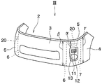
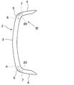
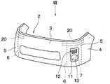
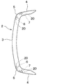
- FIG. 4 is an enlarged view of the back surface of the bumper cover as seen from the IV direction of FIG. It is explanatory drawing explaining a state when an object collides with the front part of a bumper cover. It is explanatory drawing explaining a state when an object collides with the side part of a bumper cover. It is a perspective view of the bumper cover which attached the piezoelectric sensor of 2nd Embodiment. It is a top view of the VIII direction of FIG.
- FIG. 26 is a sectional view taken along line XXVI-XXVI in FIG. 25. It is a perspective view which shows the left front part of the vehicle which attached the piezoelectric sensor of 9th Embodiment. It is a perspective view which shows the left front part of the vehicle which attached the piezoelectric sensor of 10th Embodiment. It is a perspective view which shows the left front part of the vehicle which attached the piezoelectric sensor of 11th Embodiment.
- the collision detection apparatus detects that an object such as a pedestrian collides with a bumper cover provided in a vehicle.
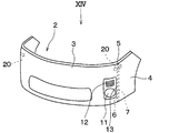
- the bumper cover 2 provided in the vehicle 1 on which the collision detection device is mounted will be described.
- the bumper cover 2 includes a front part 3 located in front of the vehicle, a side part 4 located on the side of the vehicle, and a bend having a smaller radius of curvature than the front part 3 and the side part 4. Part 5.
- the boundary between the front portion 3 and the bent portion 5 is indicated by a broken line 6, and the boundary between the side portion 4 and the bent portion 5 is indicated by a broken line 7, but the front portion 3, the side portion 4 and the bent portion 5 are illustrated. Is formed continuously.
- the bumper cover 2 is fixed to vehicle body parts around the bumper cover 2.
- the fixing portion 8 that fixes the bumper cover 2 to the vehicle body parts around the bumper cover 2 is indicated by a broken line.
- the vehicle body parts around the bumper cover 2 and the fixing portion 8 of the bumper cover 2 are fixed by bolts or the like as fastening members.
- the vehicle 1 on which the bumper cover 2 is installed includes headlights 10 on the front side of the vehicle and on the left and right in the vehicle width direction.
- the headlight 10 is provided above the bumper cover 2.
- the bumper cover 2 is provided with a mounting hole 13 at a position below the headlight 10 to which at least one of the fog lamp 11 and the ventilation duct 12 is attached.
- the collision detection device includes a piezoelectric sensor 20, a signal processing unit 30, and the like.
- a piezoelectric sensor 20 for detecting a collision of an object with the bumper cover 2 is attached to the back surface of the bumper cover 2.
- the piezoelectric sensor 20 is an example of a deformation detection unit that can detect deformation of the bumper cover 2.
- the piezoelectric sensor 20 is attached to a position including the bent portion 5 on the back surface of the bumper cover 2.
- the piezoelectric sensor 20 is attached to a position including a portion between the fog lamp 11 and the ventilation duct 12 and the headlight 10 in the bent portion 5 of the bumper cover 2.
- the area of the part is smaller than the area of the front part 3 or the side part 4. That is, as shown in FIG. 2, the distance ⁇ in the height direction of the part is shorter than the distances ⁇ and ⁇ in the height direction of the front part 3 or the side part 4.
- the piezoelectric sensor 20 is a film-like sensor having a piezoelectric element and a film portion that protects the piezoelectric element. When the piezoelectric sensor 20 is stretched in a predetermined direction, the piezoelectric sensor 20 outputs a voltage signal corresponding to the stretched length from the piezoelectric element.
- the predetermined direction is referred to as a sensitivity direction D of the piezoelectric sensor 20.
- the sensitivity direction D of the piezoelectric sensor 20 is indicated by a double-headed arrow with a symbol D.
- the piezoelectric sensor 20 is attached so that the sensitivity direction D is along the longitudinal direction of the bumper cover 2.
- the signal output from the piezoelectric sensor 20 is transmitted to the signal processing unit 30.
- the signal processing unit 30 determines whether an object has collided with the bumper cover 2 based on a signal input from the piezoelectric sensor 20. Specifically, the signal processing unit 30 stores a predetermined threshold corresponding to the vehicle speed of the vehicle 1. The signal processing unit 30 can determine that a person has collided with the bumper cover 2 when the output of the piezoelectric sensor 20 is larger than the predetermined threshold value.
- the electronic control device mounted on the vehicle 1 can execute a technique for instantly lifting the rear of the hood of the vehicle 1 and alleviating the impact on the person who rides on the hood.
- the electronic control device can also execute a technique for inflating an air bag installed outside the A-pillar and the cowl to mitigate a shock to a person.
- the bumper cover 2 undergoes local deformation and overall deformation.
- the local deformation is a deformation of the bumper cover 2 around the collision location.
- the overall deformation is a deformation in the vicinity of the fixed portion 8 that occurs when the entire bumper cover 2 is displaced with the fixed portion 8 as a fulcrum.
- the piezoelectric sensor 20 of the first embodiment can detect the local deformation of the bumper cover 2.
- FIG. 5 schematically shows a state when the object 50 collides with the front part 3 of the bumper cover 2.
- the object 50 collides with the front surface portion 3 of the bumper cover 2, as shown by arrows S1 and S2, elongation occurs around the collision location, and local deformation occurs.
- the curvature radius of the bent portion 5 of the bumper cover 2 is smaller than the curvature radius of the front surface portion 3 and the curvature radius of the side surface portion 4. Therefore, the rigidity of the bent part 5 is larger than the rigidity of the front part 3 and the rigidity of the side part 4. Therefore, local deformation that occurs when the object 50 collides with the front surface portion 3 of the bumper cover 2 is transmitted to the bent portion 5, and is difficult to be transmitted to the side surface portion 4 beyond the bent portion 5. Therefore, the piezoelectric sensor 20 attached to the bent portion 5 can output a signal corresponding to the collision force when the object 50 collides with the front surface portion 3 of the bumper cover 2.
- FIG. 6 schematically shows a state when the object 50 collides with the side surface portion 4 of the bumper cover 2.
- the object 50 collides with the side surface portion 4 of the bumper cover 2 as shown by arrows S3 and S4, elongation occurs in the area around the collision area, and local deformation occurs.
- This local deformation is transmitted to the bent portion 5 and hardly transmitted to the front portion 3 beyond the bent portion 5. Therefore, the piezoelectric sensor 20 attached to the bent portion 5 can output a signal corresponding to the collision force when the object 50 collides with the side surface portion 4 of the bumper cover 2.
- the collision detection device can detect local deformation of the bumper cover 2 regardless of whether the object 50 collides with the front surface portion 3 or the side surface portion 4 of the bumper cover 2. Is possible.
- the piezoelectric sensors 40 included in the collision detection device of the comparative example are respectively attached to the front surface portion 3 and the side surface portion 4 of the back surface of the bumper cover 2.
- FIG. 23 schematically shows a state when the object 50 collides with the front portion 3 of the bumper cover 2.
- the object 50 collides with the front surface portion 3 of the bumper cover 2 as shown by arrows S1 and S2, elongation occurs around the collision location, and local deformation occurs. As described above, this local deformation is transmitted to the bent portion 5 and hardly transmitted to the side surface portion 4 beyond the bent portion 5. Therefore, when the object 50 collides with the front part 3 of the bumper cover 2, the piezoelectric sensor 40 attached to the front part 3 outputs a signal corresponding to the collision force. On the other hand, the piezoelectric sensor 40 attached to the side surface portion 4 does not output a signal corresponding to the collision force.
- FIG. 24 schematically shows a state when the object 50 collides with the side surface portion 4 of the bumper cover 2.
- the object 50 collides with the side surface portion 4 of the bumper cover 2 as shown by arrows S3 and S4, elongation occurs in the area around the collision area, and local deformation occurs. As described above, this local deformation is transmitted to the bent portion 5 and is not easily transmitted to the front portion 3 beyond the bent portion 5. Therefore, when the object 50 collides with the side surface portion 4 of the bumper cover 2, the piezoelectric sensor 40 attached to the side surface portion 4 outputs a signal corresponding to the collision force. On the other hand, the piezoelectric sensor 40 attached to the front portion 3 does not output a signal corresponding to the collision force.
- the collision detection device of the comparative example detects the local deformation of the bumper cover 2 by attaching the piezoelectric sensors 40 to the front surface portion 3 and the side surface portion 4 of the bumper cover 2, respectively.
- the collision detection device of the first embodiment has the following operational effects.
- the piezoelectric sensor 20 included in the collision detection device is attached to a position including the bent portion 5 on the back surface of the bumper cover 2.
- the piezoelectric sensor 20 can output a signal corresponding to the collision. It is. Therefore, in this collision detection device, the piezoelectric sensor 20 is not attached to the front surface portion 3 and the side surface portion 4 by attaching the piezoelectric sensor 20 to the bent portion 5 or is attached to the front surface portion 3 and the side surface portion 4. It is possible to reduce the number of Therefore, this collision detection device can reduce the number of parts and simplify the configuration by reducing the number of piezoelectric sensors 20 and the number of wires connecting the piezoelectric sensors 20 and the signal processing unit 30. it can.
- the piezoelectric sensor 20 is attached to the bent portion 5 at a position including a portion between the fog lamp 11 and the ventilation duct 12 and the headlight 10.
- the area of the part to which the piezoelectric sensor 20 is attached is smaller than the area of the front part 3 or the side part 4. Therefore, when the object 50 collides with the front part 3 or the side part 4 of the bumper cover 2, the stress of local deformation around the collision part is concentrated and transmitted to the bent part 5. Thereby, the elongation of the bent part 5 becomes large. Therefore, it is possible to increase the output of the piezoelectric sensor 20 by attaching the piezoelectric sensor 20 to the bent portion 5.
- the piezoelectric sensor 20 is attached so that the sensitivity direction D is along the longitudinal direction of the bumper cover 2.
- the Pampa cover has a rigidity in the longitudinal direction smaller than that in the short direction. Therefore, when the object 50 collides with the bumper cover, the deformation amount in the longitudinal direction of the bumper cover becomes larger than the deformation amount in the short direction. Therefore, the output of the piezoelectric sensor 20 can be increased by setting the sensitivity direction D of the piezoelectric sensor 20 along the longitudinal direction of the bumper cover 2.
- the second embodiment is different from the first embodiment in that the mounting position and shape of the piezoelectric sensor 20 are changed with respect to the first embodiment, and the others are substantially the same as the first embodiment. Only the part will be described.
- the piezoelectric sensor 20 included in the collision detection device is attached across the front portion 3, the bent portion 5, and the side portion 4. Therefore, the piezoelectric sensor 20 of the second embodiment also reliably outputs a signal corresponding to the collision, even when the object 50 collides with any position of the front surface portion 3, the side surface portion 4, or the bent portion 5 of the bumper cover 2. Is possible.
- FIG. 9 schematically shows a state when the object 50 collides with the front portion 3 of the bumper cover 2.
- elongation occurs in the area around the collision location, and local deformation occurs.
- the rigidity of the front portion 3 is smaller than the rigidity of the bent portion 5
- the amount of deformation of the front portion 3 is that of the bent portion 5. It becomes larger than the amount of deformation. Therefore, the elongation of the piezoelectric sensor 20 increases due to the difference in deformation amount between the front portion 3 and the bent portion 5. Therefore, in the second embodiment, the output of the piezoelectric sensor 20 can be increased.
- FIG. 10 schematically shows a state when the object 50 collides with the side surface portion 4 of the bumper cover 2.
- elongation occurs around the collision location, and deformation occurs.
- the rigidity of the side surface portion 4 is smaller than the rigidity of the bent portion 5, when the object 50 collides with the side surface portion 4 of the bumper cover 2, the deformation amount of the side surface portion 4 is It becomes larger than the amount of deformation. Therefore, the elongation of the piezoelectric sensor 20 increases due to the difference in deformation amount between the side surface portion 4 and the bent portion 5. Therefore, in the second embodiment, the output of the piezoelectric sensor 20 can be increased.
- a collision detection apparatus according to a third embodiment will be described.
- the third embodiment is obtained by changing the mounting position and shape of the piezoelectric sensor 20 with respect to the first and second embodiments, and the other is substantially the same as the first and second embodiments. Only the parts different from the first and second embodiments will be described.
- the collision detection device includes the piezoelectric sensor 20 attached over the front portion 3 and the bent portion 5, and the side portion 4 and the bent portion 5. And an attached piezoelectric sensor 20. Therefore, in the piezoelectric sensor 20 of the third embodiment, even when the object 50 collides with any position of the front surface portion 3, the side surface portion 4, or the bent portion 5 of the bumper cover 2, as in the first and second embodiments. It is possible to reliably output a signal corresponding to the collision.
- the front portion 3 is caused by the difference in deformation amount between the front portion 3 and the bent portion 5.
- the piezoelectric sensor 20 attached over the bent portion 5 is greatly deformed.
- the piezoelectric sensor 20 attached across the side surface portion 4 and the bent portion 5 is caused by the difference in deformation amount between the side surface portion 4 and the bent portion 5. Deforms greatly. Therefore, also in the third embodiment, the output of the piezoelectric sensor 20 can be increased.
- the piezoelectric sensor 20 having a smaller area can be used in the third embodiment than in the second embodiment, the output of the piezoelectric sensor 20 can be increased.
- the bumper cover 2 of the fourth embodiment has a smaller radius of curvature of the bent portion 5 than the bumper cover 2 described in the first to third embodiments, and the bent portion. 5 has a small area.
- the piezoelectric sensor 20 provided in the collision detection device is attached to a position including the bent portion 5 on the back surface of the bumper cover 2.
- the piezoelectric sensor 20 is attached across the front part 3, the bent part 5, and the side part 4.
- the piezoelectric sensor 20 of the fourth embodiment also has the same structure as the first to third embodiments, even when the object 50 collides with any position of the front surface portion 3, the side surface portion 4 or the bent portion 5 of the bumper cover 2. It is possible to reliably output a signal corresponding to the collision.
- the piezoelectricity is caused by the difference in deformation amount between the front portion 3 and the bent portion 5.
- the sensor 20 is greatly deformed.
- the piezoelectric sensor 20 is greatly deformed due to the difference in deformation amount between the side surface portion 4 and the bent portion 5. Therefore, also in the fourth embodiment, the output of the piezoelectric sensor 20 can be increased.
- a collision detection apparatus according to a fifth embodiment will be described.
- the mounting position of the piezoelectric sensor 20 is changed with respect to the first to fourth embodiments, and the others are substantially the same as the first to fourth embodiments. Only parts different from the first to fourth embodiments will be described.
- a fixing portion 8 for fixing the bumper cover 2 to the vehicle body parts around the bumper cover 2 is provided on the outer edge portion of the bumper cover 2.
- the fixing portion 8 is a place where a hole for inserting the bolt 14 is formed in a part of a flange provided on the outer edge of the bumper cover main body.
- the vehicle body parts around the bumper cover 2 and the fixing portion 8 of the bumper cover 2 are fixed by a bolt 14 or the like as a fastening member.
- the piezoelectric sensor 20 included in the collision detection device of the fifth embodiment is attached to a position including the vicinity of the fixed portion 8 on the back surface of the bumper cover 2.
- the piezoelectric sensor 20 is attached to a position including the vicinity of the fixing portions 8 arranged at both ends in the longitudinal direction among the plurality of fixing portions 8 provided on the bumper cover 2.
- the vicinity of the fixing portion 8 refers to a portion where the fixing portion 8 is deformed around the fixing portion 8 when the entire deformation of the bumper cover 2 occurs.
- “in the vicinity of the fixing portion 8” refers to a range within 50 mm, for example, from the connection position between the flange and the bumper cover main body.
- a range “in the vicinity of the fixed portion 8” is indicated by a broken line N.
- the piezoelectric sensor 20 is attached so that the sensitivity direction D is directed from the fixed portion 8 toward the central region side of the side surface portion 4. By attaching the piezoelectric sensor 20 in this way, the output of the piezoelectric sensor 20 can be increased.
- the piezoelectric sensor 20 attached in the vicinity of the fixed portion 8 is preferably more sensitive than the piezoelectric sensor 20 attached to the bent portion 5 described in the first to fourth embodiments. Therefore, even when the extension of the bumper cover 2 due to the overall deformation is smaller than the extension of the bumper cover 2 due to the local deformation, the signal processing unit 30 can reliably detect the output of the piezoelectric sensor 20.
- the bumper cover 2 undergoes local deformation and overall deformation.
- the whole deformation is a deformation in the vicinity of the fixed portion 8 caused by the displacement of the entire bumper cover 2 with the fixed portion 8 as a fulcrum.
- the piezoelectric sensor 20 of the fifth embodiment can detect the entire deformation of the bumper cover 2.
- FIG. 18 schematically shows a state when the object 50 collides with the front part 3 of the bumper cover 2.
- the entire bumper cover 2 is displaced with the fixed portions 8 disposed at both ends in the longitudinal direction of the bumper cover 2 as fulcrums as indicated by arrows S5.
- the position of the fixing portion 8 is hardly displaced. Therefore, as shown by an arrow S6, stress concentrates on a portion of the bumper cover 2 in the vicinity of the fixed portion 8, and elongation occurs, resulting in overall deformation. Therefore, when the object 50 collides with the front part 3 of the bumper cover 2, the piezoelectric sensor 20 attached at a position including the vicinity of the fixed part 8 outputs a signal corresponding to the collision force.
- FIG. 19 schematically shows a state when the object 50 collides with the side surface portion 4 of the bumper cover 2.
- the entire bumper cover 2 has the fixed portions 8 arranged at both ends in the longitudinal direction of the bumper cover 2 as fulcrums. Displace. At that time, the position of the fixing portion 8 is hardly displaced. For this reason, as indicated by the arrow S8, the bumper cover 2 is stretched in the vicinity of the fixed portion 8, and the entire deformation occurs. Therefore, when the object 50 collides with the side surface portion 4 of the bumper cover 2, the piezoelectric sensor 20 attached at a position including the vicinity of the fixed portion 8 outputs a signal corresponding to the collision force.
- the collision detection device can detect the entire deformation of the bumper cover 2 regardless of whether the object 50 collides with the front surface portion 3 or the side surface portion 4 of the bumper cover 2. Is possible.
- the collision detection apparatus of the fifth embodiment has the following operational effects.
- the piezoelectric sensor 20 included in the collision detection device is attached to a position including the vicinity of the fixed portion 8 on the back surface of the bumper cover 2.
- the piezoelectric sensor 20 can output a signal corresponding to the collision. is there. Therefore, in this collision detection device, the piezoelectric sensor 20 is attached to a position including the vicinity of the fixed portion 8, so that the piezoelectric sensor 20 is not attached to the front face portion 3 and the bent portion 5 or the number of piezoelectric sensors 20 is reduced. It is possible. Therefore, this collision detection device can reduce the number of parts and simplify the configuration by reducing the number of piezoelectric sensors 20 and the number of wires connecting the piezoelectric sensors 20 and the signal processing unit 30. it can.
- the piezoelectric sensor 20 is attached to the bumper cover 2 in the vicinity of the fixed portion 8 disposed at the end portion in the longitudinal direction.
- the fixing portion 8 arranged at the end in the longitudinal direction of the bumper cover 2 is fixed to the tire house of the vehicle 1 or a vehicle body part in the vicinity thereof, and has high rigidity. For this reason, when the object 50 collides with the bumper cover 2, the fixed portion 8 is hardly displaced, so stress concentrates in the vicinity of the fixed portion 8 and the deformation near the fixed portion 8 is large. Become. Therefore, it is possible to increase the output of the piezoelectric sensor 20 by attaching the piezoelectric sensor 20 to a position including the vicinity of the fixed portion 8.
- the piezoelectric sensor 20 is attached such that the sensitivity direction D is directed from the fixed portion 8 toward the central region side of the side surface portion 4.
- the deformation amount of the portion from the fixed portion 8 toward the central region side of the side surface portion 4 becomes large. Therefore, it is possible to increase the output of the piezoelectric sensor 20 by attaching the piezoelectric sensor 20 according to the part.
- FIG. 6 A collision detection apparatus according to a sixth embodiment will be described.
- the sixth embodiment is obtained by changing the shape and mounting position of the piezoelectric sensor 20 with respect to the fifth embodiment, and is otherwise substantially the same as the fifth embodiment. Only the different parts will be described.
- the film portion 21 that protects the piezoelectric element is formed larger than the piezoelectric element 22.
- a hole 23 is provided at a position away from the piezoelectric element 22 in the film portion 21.
- Bolts 14 as fastening members are inserted through holes 23 provided in the film part 21. Accordingly, the piezoelectric sensor 20 is fastened together with the vehicle body parts around the bumper cover 2 and the fixing portion 8 of the bumper cover 2. The piezoelectric sensor 20 is attached from the fixed portion 8 to the vicinity of the fixed portion 8.
- the piezoelectric sensor 20 when the object 50 collides with the bumper cover 2, the piezoelectric sensor 20 is greatly deformed due to the difference between the deformation amount of the fixing portion 8 and the deformation amount near the fixing portion 8. Therefore, the output of the piezoelectric sensor 20 can be increased.
- a collision detection apparatus according to a seventh embodiment will be described.
- the mounting position of the piezoelectric sensor 20 is changed with respect to the first to sixth embodiments, and the rest is substantially the same as the first to sixth embodiments. Only the differences from the sixth embodiment will be described.
- the piezoelectric sensor 20 included in the collision detection device of the seventh embodiment is attached to the fixed portion 8 provided near the front portion 3 of the bumper cover 2 or in the vicinity of the fixed portion 8. ing.
- the piezoelectric sensor 20 is also attached to a position including the bent portion 5 as the first piezoelectric sensor.
- the piezoelectric sensor 20 is also attached to a position including the fixed portion 8 or the vicinity of the fixed portion 8 disposed at both ends in the longitudinal direction as the second piezoelectric sensor.
- the collision detection device according to the seventh embodiment can be applied to the bumper cover 2 regardless of whether the object 50 collides with the front portion 3 or the side portion 4 of the bumper cover 2. It is possible to detect the overall deformation.
- a collision detection apparatus according to an eighth embodiment will be described.
- the mounting position of the piezoelectric sensor 20 is changed with respect to the first to fourth embodiments, and the other parts are substantially the same as those of the first to fourth embodiments. Only the parts different from the fourth embodiment will be described.
- a ridge line 9 bent so as to protrude toward the front side of the vehicle around the mounting hole 13 to which at least one of the fog lamp 11 and the ventilation duct 12 is attached to the bumper cover 2 is provided. Is formed.
- a line obtained by extending a part of the ridge line 9 located on the outer side in the vehicle width direction along the back surface of the bumper cover 2 among the ridge lines 9 is defined as the extension line EL.
- the piezoelectric sensor 20 it is possible to increase the output of the piezoelectric sensor 20 by attaching the piezoelectric sensor 20 so as to include the extension line EL on the back surface of the bumper cover 2.
- the bumper cover 2 since the bumper cover 2 is well deformed in a direction orthogonal to the extension line EL, the bumper cover 2 includes the extension line EL, and the extension line EL and the sensitivity direction D of the piezoelectric sensor 20 are substantially orthogonal to each other. It is preferable to attach the piezoelectric sensor 20.
- the sensitivity direction D of the piezoelectric sensor 20 is shown with the dashed-dotted line.
- the sensitivity direction D of the piezoelectric sensor 20 and the extension line EL are substantially orthogonal means that the angle formed by the extension line EL and the sensitivity direction D of the piezoelectric sensor 20 is 90 °.
- the error it shall include an error of ⁇ 15 °.
- the extension line EL and the sensitivity direction D of the piezoelectric sensor 20 are orthogonal to each other includes an angle between the extension line EL and the sensitivity direction D of the piezoelectric sensor 20 in a range of 75 ° to 105 °. It is a waste. That is, it can be said that the piezoelectric sensor 20 is attached so that the sensitivity direction D and the extension line EL intersect so that a signal is output from the piezoelectric sensor 20 when an object collides with the bumper cover 2. . That is, as long as it is attached so that a signal is output from the piezoelectric sensor 20 when an object collides with the bumper cover 2, the bumper cover 2 may not be orthogonal but may be attached.
- one sheet is obtained by attaching the piezoelectric sensor 20 on the extension line EL where strain concentrates on the bumper cover 2 at a plurality of collision positions among the front surface portion 3 and the side surface portion 4 of the bumper cover 2.
- the hit piezoelectric sensor 20 can detect a wide area collision. Furthermore, by attaching the piezoelectric sensor 20 to the bumper cover 2 so that the sensitivity direction D of the piezoelectric sensor 20 and the extension line EL are substantially orthogonal to each other, the output of the piezoelectric sensor 20 is increased and a collision of a wider area is detected. Is possible.
- this collision detection apparatus can reduce the number of piezoelectric sensors 20 that are not attached to the positions deviating from the extension line EL or that are attached to positions deviating from the extension line EL. Therefore, this collision detection device can reduce the number of parts and simplify the configuration by reducing the number of piezoelectric sensors 20 and the number of wires connecting the piezoelectric sensors 20 and the signal processing unit 30. it can.
- (Ninth embodiment) A collision detection apparatus according to the ninth embodiment will be described.
- the ninth embodiment is obtained by changing the mounting position of the piezoelectric sensor 20 with respect to the first to fourth embodiments.
- the other aspects are substantially the same as those of the first to fourth embodiments. Only the parts different from the fourth embodiment will be described.
- the piezoelectric sensor 20 is attached so as to be positioned on the extension line EL in the bumper cover 2. Specifically, in the ninth embodiment, the piezoelectric sensor 20 is attached such that the central portion of the piezoelectric sensor 20 is positioned on the extension line EL. Thereby, when an object collides with one of the front part 3 or the side part 4 of the bumper cover 2, the one part of the sensitivity direction D of the piezoelectric sensor 20 differs from the other part across the extension EL. become. Therefore, the output of the piezoelectric sensor 20 can be increased.
- the central portion of the piezoelectric sensor 20 includes a range portion of 10% of the entire length of the piezoelectric sensor 20 in the sensitivity direction D in addition to the center position DS of the piezoelectric sensor 20 in the sensitivity direction D.
- the ninth embodiment it is possible to increase the output of the piezoelectric sensor 20 by attaching the piezoelectric sensor 20 to the bumper cover 2 so that the center portion of the piezoelectric sensor 20 is positioned on the extension line EL. Therefore, collision of a wider area can be detected by the piezoelectric sensor 20 per sheet.
- the tenth embodiment is a combination of the eighth embodiment and the ninth embodiment described above.
- the piezoelectric sensor 20 has a sensitivity direction D of the piezoelectric sensor 20 and an extension line EL substantially orthogonal to each other on the back surface of the bumper cover 2 and the piezoelectric sensor 20. It is attached so that the center part of may be located on the extension line EL.
- the output of the piezoelectric sensor 20 can be further increased, and a collision of a wider area can be detected by the piezoelectric sensor 20 per sheet.
- a collision detection apparatus according to an eleventh embodiment will be described.
- the tenth embodiment is obtained by changing the mounting position of the piezoelectric sensor 20 with respect to the eighth to tenth embodiments described above, and the other parts are substantially the same as the eighth to tenth embodiments. Only portions different from the eighth to tenth embodiments will be described.
- the piezoelectric sensor 20 is attached to the back surface of the bumper cover 2 at a position between the upper portion of the mounting hole 13 of the bumper cover 2 and the lower portion of the headlight 10. Yes. Specifically, in the eleventh embodiment, the piezoelectric sensor 20 is attached to the back surface of the bumper cover 2 at a position including the center position between the upper portion of the mounting hole 13 of the bumper cover 2 and the lower portion of the headlight 10. . Specifically, in FIG. 29, the distance L1 between the upper part of the mounting hole 13 of the bumper cover 2 and the center of the piezoelectric sensor 20 and the distance L2 between the lower part of the headlight 10 and the center of the piezoelectric sensor 20 are the same. .
- a ridgeline 91 that extends along the headlight 10 is formed at a portion of the bumper cover 2 positioned below the headlight 10 so as to be convex toward the front or side of the vehicle.
- the portion of the ridge line 91 formed under the headlight 10 has higher rigidity than other portions.
- the ridgeline 9 that is bent so as to protrude toward the front side of the vehicle is also formed around the mounting hole 13 of the bumper cover 2.
- the portion of the ridge line 9 around the mounting hole 13 has higher rigidity than other portions.
- the bumper cover 2 has a lower rigidity of the portion between the ridge lines 91 and 9 than the rigidity of the ridge line 91 below the headlight 10 and the ridge line 9 around the mounting hole 13 of the bumper cover 2. It has become. Among these, it can be said that the center position between the upper portion of the mounting hole 13 of the bumper cover 2 and the lower portion of the headlight 10 is a portion that is well deformed in accordance with the collision of an object.
- the piezoelectric sensor 20 is attached to the back surface of the bumper cover 2 at a position including the center position between the upper portion of the mounting hole 13 of the bumper cover 2 and the lower portion of the headlight 10. Thereby, it is possible to increase the output of the piezoelectric sensor 20 and detect a collision of a wider area. Furthermore, it is preferable that the piezoelectric sensor 20 is attached so that the sensitivity direction D and the extension line EL are substantially orthogonal to each other and the center portion of the piezoelectric sensor 20 is positioned on the extension line EL. Also in the eleventh embodiment, it is possible to achieve the same effects as the eighth to tenth embodiments.
- the piezoelectric sensor 20 has the sensitivity direction D of the piezoelectric sensor 20 and the extension line EL substantially orthogonal to each other on the back surface of the bumper cover 2 and the center of the piezoelectric sensor 20. It is preferable to attach so that a part may be located on extension line EL.
- the piezoelectric sensor 20 is preferably attached to a position on the back surface of the bumper cover 2 including a central position between the upper portion of the mounting hole 13 of the bumper cover 2 and the lower portion of the headlight 10.
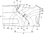
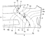
- the bumper cover 2 provided in the vehicle 1 on which the collision detection apparatus of the thirteenth embodiment is mounted includes a first bumper component 2a provided at a position including the vehicle side surface, and a second bumper cover 2 provided at the front of the vehicle. And a bumper part 2b.
- the first bumper part 2a on the right side in the vehicle width direction and the first bumper part 2a on the left side in the vehicle width direction may be parts formed integrally through the lower side of the second bumper part 2b, or the like. It may be a separate part.
- the first bumper component 2a has a part of the front part 3 located in front of the vehicle, a side part 4 located on the side of the vehicle, and a bent part 5 having a smaller radius of curvature than the front part 3 and the side part 4. is doing. Further, the first bumper component 2a is provided with a mounting hole 13 at a position located below the headlight 10 to which at least one of a fog lamp and a ventilation duct is attached.
- the second bumper part 2b has a part of the front part 3 located in front of the vehicle. That is, the first bumper component 2 a and the second bumper component 2 b are joined in the middle of the front portion 3.
- the second bumper part 2b includes a bumper grill 15 for taking air into the engine room. That is, in this specification, the bumper cover 2 includes the bumper grill 15.
- FIG. 32 shows the right half of the back surface of the bumper cover 2 in the vehicle width direction.
- the first bumper component 2 a and the second bumper component 2 b are overlapped with each other at a predetermined width, and are joined by a plurality of joining members 16 and 17.
- Examples of the joining members 16 and 17 include a locking hole and a locking claw 16, a screw 17, and a clip.
- the end of the portion where the first bumper component 2a and the second bumper component 2b overlap is indicated by a broken line 2c.
- the collision detection apparatus also includes the piezoelectric sensor 20 and the signal processing unit 30.
- the piezoelectric sensor 20 is attached to the vicinity of the boundary line 2d between the first bumper component 2a and the second bumper component 2b on the back surface of the bumper cover 2.
- the piezoelectric sensor 20 is attached to the back surface of the bumper cover 2 within a range of ⁇ 100 mm in the normal direction from the boundary line 2d between the first bumper component 2a and the second bumper component 2b.
- the range is referred to as “the boundary vicinity 18 between the first bumper component 2a and the second bumper component 2b”.
- the range of the boundary vicinity part 18 is shown with the dashed-dotted line which attached
- the piezoelectric sensor 20 when an object collides with various places of the bumper cover 2 by attaching the piezoelectric sensor 20 to the boundary vicinity portion 18, the piezoelectric sensor 20 has a voltage corresponding to the collision. It is possible to output a signal.
- the bumper cover 2 when an object collides with an arbitrary place of the bumper cover 2, the bumper cover 2 has a first bumper part 2a and a second bumper part 2b in the surface direction.
- the boundary line 2d is deformed in the normal direction. Therefore, the piezoelectric sensor 20 is preferably attached so that the direction of the sensitivity direction D intersects the boundary line 2d between the first bumper component 2a and the second bumper component 2b. Thereby, the output of the piezoelectric sensor 20 can be increased.
- the bumper cover 2 joins the first bumper part 2a and the second bumper part 2b. , 17 as a starting point. That is, stress concentration occurs in the bumper cover 2 where the shape changes rapidly. Therefore, it is preferable to attach the piezoelectric sensor 20 so that the direction of the sensitivity direction D faces the bonding members 16 and 17. Thereby, the output of the piezoelectric sensor 20 can be increased.
- the bumper cover 2 when an object collides with an arbitrary place of the bumper cover 2, the bumper cover 2 is deformed by the deformation of the first bumper part 2a compared to the deformation amount of the second bumper part 2b. The amount tends to increase. For this reason, the piezoelectric sensor 20 is preferably attached to the first bumper component 2a. Thereby, the output of the piezoelectric sensor 20 can be increased.
- the signal output from the piezoelectric sensor 20 is transmitted to the signal processing unit 30.
- the signal processing unit 30 determines whether an object has collided with the bumper cover 2 based on a signal input from the piezoelectric sensor 20. Specifically, the signal processing unit 30 stores a predetermined threshold corresponding to the vehicle speed of the vehicle 1. The signal processing unit 30 can determine that a person has collided with the bumper cover 2 when the output of the piezoelectric sensor 20 is larger than the predetermined threshold value.
- This effect confirmation test was conducted using a test apparatus as shown in FIG. That is, in this test apparatus, a part of the vehicle 1 including the front bumper (hereinafter referred to as a cut body 61) is fixed on the test stand 60, and the impactor 62 is moved from the front of the cut body 61 to the front bumper at a predetermined speed. It is a thing to collide with.
- the front bumper includes a bumper cover 2 and a bumper reinforcement (not shown) provided inside the bumper cover 2.
- a plurality of piezoelectric sensors 20 are attached to the back surface of the bumper cover 2.
- the signal intensity output from the plurality of piezoelectric sensors 20 when the impactor 62 collides with the bumper cover 2 that is, the magnitude of the voltage was detected.
- FIG. 34 is a diagram in which a stress distribution generated in the bumper cover 2 when the impactor 62 collides with a predetermined position on the boundary between the first bumper part 2a and the second bumper part 2b is analyzed.
- This analysis diagram shows the right half of the back surface of the bumper cover 2 in the vehicle width direction.
- the analysis figure referred by the below-mentioned description also shows the right half of the vehicle width direction among the back surfaces of the bumper cover 2.
- the collision position of the impactor 62 against the bumper cover 2 is indicated by reference numeral I1.
- the arrow S10 in FIG. 34 in this analysis view, it can be seen that stress concentration occurs in the boundary vicinity 18 between the first bumper component 2a and the second bumper component 2b. Therefore, by attaching the piezoelectric sensor 20 to the boundary vicinity 18, the output of the piezoelectric sensor 20 can be increased.
- the bumper cover 2 has a larger stress generated in the first bumper component 2a than the stress generated in the second bumper component 2b. Can be seen. Therefore, by attaching the piezoelectric sensor 20 to the boundary vicinity 18 between the first bumper component 2a and the second bumper component 2b and the first bumper component 2a, the output of the piezoelectric sensor 20 can be increased.
- FIG. 35 is an analysis of the stress distribution generated in the bumper cover 2 when the impactor 62 collides with a predetermined position of the first bumper part 2a.
- FIG. 35 shows the impactor 62 in a state of colliding with the bumper cover 2. That is, the position where the impactor 62 and the bumper cover 2 overlap is the collision position.
- the arrow S11 in FIG. 35 in this analysis view, it can be seen that stress concentration occurs starting from the joining members 16 and 17 that join the first bumper part 2a and the second bumper part 2b. Therefore, by attaching the piezoelectric sensor 20 to the boundary vicinity 18 with the sensitivity direction D of the piezoelectric sensor 20 facing the joining members 16 and 17, the output of the piezoelectric sensor 20 can be increased.
- FIG. 36 is an analysis of the stress distribution generated in the bumper cover 2 when the impactor 62 collides with another position on the boundary between the first bumper part 2a and the second bumper part 2b. 36 also includes the impactor 62 in a state of colliding with the bumper cover 2. That is, the position where the impactor 62 and the bumper cover 2 overlap is the collision position. As shown by arrows S12 and S13 in FIG. 36, in this analysis view, it can be seen that stress concentration occurs starting from the joining members 16 and 17 that join the first bumper part 2a and the second bumper part 2b. . Therefore, by attaching the piezoelectric sensor 20 to the boundary vicinity 18 with the sensitivity direction D of the piezoelectric sensor 20 facing the bonding members 16 and 17, the output of the piezoelectric sensor 20 can be increased.
- the piezoelectric sensor 20 is attached to the boundary vicinity 18 between the first bumper component 2a and the second bumper component 2b. That is, the inventors, through experiments and simulations, distorted the bumper cover 2 when the boundary vicinity 18 between the first bumper part 2a and the second bumper part 2b collides with an arbitrary position of the bumper cover 2. It was found that this is the part where it concentrates.
- the piezoelectric sensor 20 can output a signal corresponding to the collision. .
- this collision detection apparatus can reduce the number of piezoelectric sensors 20 attached to the bumper cover 2. Therefore, this collision detection device can reduce the number of parts and simplify the configuration by reducing the number of piezoelectric sensors 20 and the number of wires connecting the piezoelectric sensors 20 and the signal processing unit 30. it can.
- the piezoelectric sensor 20 is attached so that the direction of the sensitivity direction D of the piezoelectric sensor 20 intersects the boundary line 2d between the first bumper component 2a and the second bumper component 2b.
- the bumper cover 2 is deformed in the normal direction with respect to the boundary line 2d between the first bumper part 2a and the second bumper part 2b in the surface direction. Therefore, it is possible to increase the output of the piezoelectric sensor 20 by attaching the direction of the sensitivity direction D of the piezoelectric sensor 20 so as to intersect the boundary line 2d between the first bumper component 2a and the second bumper component 2b. It is.
- the piezoelectric sensor 20 is attached so that the sensitivity direction D faces the joining members 16 and 17 that join the first bumper part 2a and the second bumper part 2b.
- the bumper cover 2 is deformed starting from the joining members 16 and 17 that join the first bumper part 2a and the second bumper part 2b. Therefore, the output of the piezoelectric sensor 20 can be increased by attaching the direction of the sensitivity direction D of the piezoelectric sensor 20 toward the joining members 16 and 17.
- the piezoelectric sensor 20 is attached to the boundary vicinity 18 and the first bumper component 2a.
- the bumper cover 2 tends to have a larger deformation amount of the first bumper component 2a than a deformation amount of the second bumper component 2b. For this reason, it is possible to increase the output of the piezoelectric sensor 20 by attaching the piezoelectric sensor 20 to the first bumper component 2a.
- the piezoelectric sensor 20 of the fourteenth embodiment is also attached to the boundary vicinity 18 between the first bumper part 2a and the second bumper part 2b on the back surface of the first bumper part 2a.
- the piezoelectric sensor 20 is attached so that the direction of the sensitivity direction D is along the boundary line 2d between the first bumper component 2a and the second bumper component 2b.
- the boundary vicinity 18 between the first bumper part 2a and the second bumper part 2b is a part where strain is concentrated on the bumper cover 2 when an object collides with an arbitrary place of the bumper cover 2.
- the collision detection apparatus can reduce the number of components and simplify the configuration by reducing the number of piezoelectric sensors 20 attached to the bumper cover 2.
- the piezoelectric sensor 20 of the fifteenth embodiment is attached to the boundary vicinity 18 between the first bumper component 2a and the second bumper component 2b on the back surface of the second bumper component 2b.
- the boundary vicinity 18 between the first bumper part 2a and the second bumper part 2b is a part where strain is concentrated on the bumper cover 2 when an object collides with an arbitrary place of the bumper cover 2. Therefore, according to the experiments and simulations of the inventors, even when the piezoelectric sensor 20 is attached in this way, when an object collides with the bumper cover 2, the piezoelectric sensor 20 outputs a signal corresponding to the collision. Is possible.
- the piezoelectric sensor 20 is preferably attached so that the direction of the sensitivity direction D intersects the boundary line 2d between the first bumper component 2a and the second bumper component 2b. Thereby, the output of the piezoelectric sensor 20 can be increased.
- the bumper cover 2 when an object collides with the bumper cover 2, the bumper cover 2 is deformed starting from the joining members 16 and 17 that join the first bumper part 2a and the second bumper part 2b. That is, stress concentration occurs in the bumper cover 2 where the shape changes rapidly. Therefore, it is preferable to attach the piezoelectric sensor 20 so that the direction of the sensitivity direction D faces the bonding members 16 and 17. Thereby, the output of the piezoelectric sensor 20 can be increased.
- FIG. 39 is a diagram analyzing the stress distribution generated in the bumper cover 2 when the impactor 62 collides with a predetermined position of the second bumper part 2b.
- the collision position of the impactor 62 against the second bumper part 2b is indicated by reference numeral I2.
- the arrow S14 in FIG. 39 in this analysis view, it can be seen that stress concentration occurs starting from the joining members 16 and 17 that join the first bumper part 2a and the second bumper part 2b. Therefore, by attaching the piezoelectric sensor 20 to the boundary vicinity 18 with the sensitivity direction D of the piezoelectric sensor 20 facing the bonding members 16 and 17, the output of the piezoelectric sensor 20 can be increased.
- FIG. 40 is a diagram in which a stress distribution generated in the bumper cover 2 when the impactor 62 collides with another position of the second bumper part 2b is analyzed.
- the impactor 62 in a state of colliding with the bumper cover 2 is described. That is, the position where the impactor 62 and the bumper cover 2 overlap is the collision position.
- stress concentration occurs starting from the joining members 16 and 17 that join the first bumper part 2a and the second bumper part 2b. Can be seen. Therefore, by attaching the piezoelectric sensor 20 to the boundary vicinity 18 with the sensitivity direction D of the piezoelectric sensor 20 facing the bonding members 16 and 17, the output of the piezoelectric sensor 20 can be increased.
- the piezoelectric sensor 20 is attached to the boundary vicinity 18 between the first bumper component 2a and the second bumper component 2b and the second bumper component 2b.
- the piezoelectric sensor 20 can output a signal corresponding to the collision, even when an object collides with any position of the bumper cover 2.
- this collision detection apparatus can reduce the number of piezoelectric sensors 20 attached to the bumper cover 2. Therefore, this collision detection device can reduce the number of parts and simplify the configuration by reducing the number of piezoelectric sensors 20 and the number of wires connecting the piezoelectric sensors 20 and the signal processing unit 30. it can.
- the piezoelectric sensor 20 of the sixteenth embodiment is also attached to the boundary vicinity 18 between the first bumper component 2a and the second bumper component 2b on the back surface of the second bumper component 2b.
- the piezoelectric sensor 20 is attached such that the direction of the sensitivity direction D is along the boundary line 2d between the first bumper component 2a and the second bumper component 2b.
- the boundary vicinity 18 between the first bumper part 2a and the second bumper part 2b is a part where strain is concentrated on the bumper cover 2 when an object collides with an arbitrary place of the bumper cover 2.
- the piezoelectric sensor 20 even when the piezoelectric sensor 20 is attached in this way, when an object collides with the bumper cover 2, the piezoelectric sensor 20 outputs a signal corresponding to the collision. Is possible. Therefore, also in the collision detection device of the sixteenth embodiment, by reducing the number of piezoelectric sensors 20 attached to the bumper cover 2, the number of parts can be reduced and the configuration can be simplified.
- the piezoelectric sensor is attached to the bumper cover at a position including the bent portion.
- the piezoelectric sensor is attached to the bumper cover at a position including the vicinity of the fixed portion.
- the piezoelectric sensor is attached to the bumper cover at a position including the extension line.
- the piezoelectric sensor is attached to the vicinity of the boundary between the first bumper part and the second bumper part.
- the piezoelectric sensor may be attached to other positions in addition to the positions described in the first to sixteenth embodiments.
- the bumper cover is not limited to the shape exemplified in the above-described embodiment, and various shapes, materials, and thicknesses can be adopted.
- the bumper cover may not include one or both of a fog lamp and a ventilation duct.
- a piezoelectric sensor is exemplified as the deformation detection unit.
- various sensors that can detect the deformation of the bumper cover such as a strain gauge, an optical fiber, a pressure-sensitive rubber, and a capacitance sensor, are employed as the deformation detection unit. Is possible.
- the piezoelectric sensor or the like as the deformation detection unit is attached to the back surface of the bumper cover.
- a piezoelectric sensor or the like as a deformation detection unit may be attached to the surface of the bumper cover.
Landscapes
- Engineering & Computer Science (AREA)
- Mechanical Engineering (AREA)
- Force Measurement Appropriate To Specific Purposes (AREA)
Abstract
Dispositif de détection de collision monté sur un véhicule (1) pourvu d'un cache pare-chocs (2) qui est formé par l'assemblage, avec des éléments d'assemblage (16, 17), de premiers composants de pare-chocs (2a) disposés dans des positions comprenant les côtés de véhicule et d'un second composant de pare-chocs (2b) disposé sur l'avant de véhicule. Ce dispositif de détection de collision est pourvu d'une unité de détection de déformation (20) qui peut détecter une déformation du cache pare-chocs (2), et d'une unité de traitement de signal (30) qui détermine si un objet est entré en collision avec le cache pare-chocs (2) sur la base d'un signal entré à partir de l'unité de détection de déformation (20). L'unité de détection de déformation (20) est fixée au niveau d'une zone de limite proche (18), c'est-à-dire, un site à proximité de la limite entre le premier composant de pare-chocs (2a) et le second composant de pare-chocs (2b).
Priority Applications (1)
| Application Number | Priority Date | Filing Date | Title |
|---|---|---|---|
| DE112017005949.6T DE112017005949T5 (de) | 2016-11-24 | 2017-11-16 | Kollisionserfassungsvorrichtung |
Applications Claiming Priority (6)
| Application Number | Priority Date | Filing Date | Title |
|---|---|---|---|
| JP2016-228014 | 2016-11-24 | ||
| JP2016228014 | 2016-11-24 | ||
| JP2017-039511 | 2017-03-02 | ||
| JP2017039511 | 2017-03-02 | ||
| JP2017204495A JP6617759B2 (ja) | 2016-11-24 | 2017-10-23 | 衝突検知装置 |
| JP2017-204495 | 2017-10-23 |
Publications (1)
| Publication Number | Publication Date |
|---|---|
| WO2018097039A1 true WO2018097039A1 (fr) | 2018-05-31 |
Family
ID=62195114
Family Applications (1)
| Application Number | Title | Priority Date | Filing Date |
|---|---|---|---|
| PCT/JP2017/041355 Ceased WO2018097039A1 (fr) | 2016-11-24 | 2017-11-16 | Dispositif de détection de collision |
Country Status (1)
| Country | Link |
|---|---|
| WO (1) | WO2018097039A1 (fr) |
Citations (3)
| Publication number | Priority date | Publication date | Assignee | Title |
|---|---|---|---|---|
| JPS6133746U (ja) * | 1984-07-31 | 1986-03-01 | ダイハツ工業株式会社 | 自動車のバンパ |
| JPH09104298A (ja) * | 1995-10-12 | 1997-04-22 | Honda Motor Co Ltd | 分割されたバンパー構造体 |
| DE29719146U1 (de) * | 1997-10-28 | 1998-04-16 | Grimm Sven | Stoßmelder für Kraftwagen |
-
2017
- 2017-11-16 WO PCT/JP2017/041355 patent/WO2018097039A1/fr not_active Ceased
Patent Citations (3)
| Publication number | Priority date | Publication date | Assignee | Title |
|---|---|---|---|---|
| JPS6133746U (ja) * | 1984-07-31 | 1986-03-01 | ダイハツ工業株式会社 | 自動車のバンパ |
| JPH09104298A (ja) * | 1995-10-12 | 1997-04-22 | Honda Motor Co Ltd | 分割されたバンパー構造体 |
| DE29719146U1 (de) * | 1997-10-28 | 1998-04-16 | Grimm Sven | Stoßmelder für Kraftwagen |
Similar Documents
| Publication | Publication Date | Title |
|---|---|---|
| JP4264844B2 (ja) | 車両用衝突検知装置 | |
| EP2982547B1 (fr) | Structure de pare-chocs de véhicule à tubes de pression comprenant un capteur de détection de collision pour piétons | |
| US20090108598A1 (en) | Vehicular Front Bumper Structure | |
| JP4807594B2 (ja) | 車両用衝突検知装置 | |
| JP6617759B2 (ja) | 衝突検知装置 | |
| JP2008201272A (ja) | 衝突検知手段および保護システム | |
| JP4311744B2 (ja) | 衝突検出装置 | |
| WO2018097041A1 (fr) | Dispositif de détection de collision | |
| JP5115816B2 (ja) | 車両用衝突検知装置 | |
| WO2018097039A1 (fr) | Dispositif de détection de collision | |
| EP1717109B1 (fr) | Système de détection de collision pour véhicule | |
| JP4877295B2 (ja) | 車両用衝突検知装置 | |
| WO2018097040A1 (fr) | Dispositif de détection de collision | |
| JP7264736B2 (ja) | 衝突検知システム | |
| JP4858786B2 (ja) | 車両用衝突検知装置 | |
| JP6593647B2 (ja) | 車両用衝突検知装置 | |
| WO2016147546A1 (fr) | Dispositif de détection de collision de véhicule | |
| JP5056495B2 (ja) | 車両用衝突検知装置 | |
| JP6579051B2 (ja) | 衝突検知装置 | |
| JP5949786B2 (ja) | 歩行者衝突検知システム | |
| JP2007314159A (ja) | 車両用衝突検知装置 | |
| JP2009208642A (ja) | 車両用衝突検知装置 | |
| WO2017017902A1 (fr) | Dispositif de détection de collision de véhicule | |
| JP2017165372A (ja) | センサ取付構造 | |
| JP2017222269A (ja) | 車両のカウル構造 |
Legal Events
| Date | Code | Title | Description |
|---|---|---|---|
| 121 | Ep: the epo has been informed by wipo that ep was designated in this application |
Ref document number: 17873856 Country of ref document: EP Kind code of ref document: A1 |
|
| 122 | Ep: pct application non-entry in european phase |
Ref document number: 17873856 Country of ref document: EP Kind code of ref document: A1 |