WO2018100671A1 - Pneu - Google Patents
Pneu Download PDFInfo
- Publication number
- WO2018100671A1 WO2018100671A1 PCT/JP2016/085547 JP2016085547W WO2018100671A1 WO 2018100671 A1 WO2018100671 A1 WO 2018100671A1 JP 2016085547 W JP2016085547 W JP 2016085547W WO 2018100671 A1 WO2018100671 A1 WO 2018100671A1
- Authority
- WO
- WIPO (PCT)
- Prior art keywords
- load support
- pneumatic tire
- tire
- sidewall portion
- pair
- Prior art date
- Legal status (The legal status is an assumption and is not a legal conclusion. Google has not performed a legal analysis and makes no representation as to the accuracy of the status listed.)
- Ceased
Links
Images
















Classifications
-
- B—PERFORMING OPERATIONS; TRANSPORTING
- B60—VEHICLES IN GENERAL
- B60C—VEHICLE TYRES; TYRE INFLATION; TYRE CHANGING; CONNECTING VALVES TO INFLATABLE ELASTIC BODIES IN GENERAL; DEVICES OR ARRANGEMENTS RELATED TO TYRES
- B60C17/00—Tyres characterised by means enabling restricted operation in damaged or deflated condition; Accessories therefor
- B60C17/04—Tyres characterised by means enabling restricted operation in damaged or deflated condition; Accessories therefor utilising additional non-inflatable supports which become load-supporting in emergency
- B60C17/06—Tyres characterised by means enabling restricted operation in damaged or deflated condition; Accessories therefor utilising additional non-inflatable supports which become load-supporting in emergency resilient
-
- B—PERFORMING OPERATIONS; TRANSPORTING
- B60—VEHICLES IN GENERAL
- B60C—VEHICLE TYRES; TYRE INFLATION; TYRE CHANGING; CONNECTING VALVES TO INFLATABLE ELASTIC BODIES IN GENERAL; DEVICES OR ARRANGEMENTS RELATED TO TYRES
- B60C17/00—Tyres characterised by means enabling restricted operation in damaged or deflated condition; Accessories therefor
- B60C17/0009—Tyres characterised by means enabling restricted operation in damaged or deflated condition; Accessories therefor comprising sidewall rubber inserts, e.g. crescent shaped inserts
-
- B—PERFORMING OPERATIONS; TRANSPORTING
- B60—VEHICLES IN GENERAL
- B60C—VEHICLE TYRES; TYRE INFLATION; TYRE CHANGING; CONNECTING VALVES TO INFLATABLE ELASTIC BODIES IN GENERAL; DEVICES OR ARRANGEMENTS RELATED TO TYRES
- B60C17/00—Tyres characterised by means enabling restricted operation in damaged or deflated condition; Accessories therefor
- B60C17/009—Tyres characterised by means enabling restricted operation in damaged or deflated condition; Accessories therefor comprising annular protrusions projecting into the tyre cavity
-
- B—PERFORMING OPERATIONS; TRANSPORTING
- B60—VEHICLES IN GENERAL
- B60C—VEHICLE TYRES; TYRE INFLATION; TYRE CHANGING; CONNECTING VALVES TO INFLATABLE ELASTIC BODIES IN GENERAL; DEVICES OR ARRANGEMENTS RELATED TO TYRES
- B60C17/00—Tyres characterised by means enabling restricted operation in damaged or deflated condition; Accessories therefor
- B60C17/04—Tyres characterised by means enabling restricted operation in damaged or deflated condition; Accessories therefor utilising additional non-inflatable supports which become load-supporting in emergency
-
- B—PERFORMING OPERATIONS; TRANSPORTING
- B60—VEHICLES IN GENERAL
- B60C—VEHICLE TYRES; TYRE INFLATION; TYRE CHANGING; CONNECTING VALVES TO INFLATABLE ELASTIC BODIES IN GENERAL; DEVICES OR ARRANGEMENTS RELATED TO TYRES
- B60C17/00—Tyres characterised by means enabling restricted operation in damaged or deflated condition; Accessories therefor
- B60C17/04—Tyres characterised by means enabling restricted operation in damaged or deflated condition; Accessories therefor utilising additional non-inflatable supports which become load-supporting in emergency
- B60C17/047—Tyres characterised by means enabling restricted operation in damaged or deflated condition; Accessories therefor utilising additional non-inflatable supports which become load-supporting in emergency comprising circumferential ribs
-
- B—PERFORMING OPERATIONS; TRANSPORTING
- B60—VEHICLES IN GENERAL
- B60C—VEHICLE TYRES; TYRE INFLATION; TYRE CHANGING; CONNECTING VALVES TO INFLATABLE ELASTIC BODIES IN GENERAL; DEVICES OR ARRANGEMENTS RELATED TO TYRES
- B60C17/00—Tyres characterised by means enabling restricted operation in damaged or deflated condition; Accessories therefor
- B60C17/0009—Tyres characterised by means enabling restricted operation in damaged or deflated condition; Accessories therefor comprising sidewall rubber inserts, e.g. crescent shaped inserts
- B60C2017/0054—Physical properties or dimensions of the inserts
Definitions
- the present invention relates to a pneumatic tire that enables run-flat running with a load support, and more specifically, even when a load support is provided in a sidewall portion, rolling resistance and riding comfort during normal running are provided.
- the present invention relates to a pneumatic tire that can suppress the deterioration of the tire to a minimum and can improve the reusability after run-flat running.
- the side reinforcing layer when a side reinforcing layer made of a rubber composition is integrally formed inside the sidewall portion, the side reinforcing layer enables run-flat driving, but rolling resistance and riding comfort during normal driving deteriorate. There is a problem.
- a pneumatic tire having a large flatness ratio i.e., a pneumatic tire having a large size in the tire radial direction of the sidewall portion, it is necessary to increase the volume of the side reinforcing layer. Deterioration of comfort becomes remarkable. Therefore, in a pneumatic tire having a large flatness ratio, a side reinforcing type run flat tire is not realized at present.
- the side-reinforced pneumatic tire described above cannot be reused after run-flat running if the side reinforcing layer is damaged during run-flat running. Therefore, after run-flat running, even if there is no problem in the tire casing structure and the remaining groove of the tread part is left sufficiently, it is necessary to replace the tire itself, which is a resource saving viewpoint. Is not preferable.
- Japanese Unexamined Patent Publication No. 7-3030412 Japanese Unexamined Patent Publication No. 2003-94912 Japanese Unexamined Patent Publication No. 2007-98992 Japanese Unexamined Patent Publication No. 2009-61866
- the object of the present invention is to minimize the rolling resistance and the deterioration of riding comfort during normal running, even when a load support is provided on the sidewall portion, and after run flat running.
- An object of the present invention is to provide a pneumatic tire that can improve reusability.
- a pneumatic tire according to the present invention includes a tread portion that extends in the tire circumferential direction to form an annular shape, a pair of sidewall portions disposed on both sides of the tread portion, and the sidewall portions.
- a pneumatic tire provided with a pair of bead portions arranged on the inner side in the tire radial direction of A load support extending along the tire circumferential direction is disposed inside each sidewall portion, and the load support is detachably attached to the inner surface of the sidewall portion via a mechanical engagement tool. It is characterized by this.
- a load support extending along the tire circumferential direction is disposed inside each sidewall portion, and the load support is disposed on the inner surface of the sidewall portion via a mechanical engagement tool. It is possible to achieve stable run-flat running, and compared with the case where a side reinforcing layer made of a rubber composition is integrally formed inside the sidewall portion as in the past, during normal running. Rolling resistance and deterioration of riding comfort can be minimized.
- the load support is detachably attached to the inner surface of the sidewall portion via a mechanical engagement tool, even if the load support is damaged during run-flat running, only the load support is replaced.
- the tire itself can be reused, and the reusability after run-flat running can be improved.
- the configuration as described above can be applied to a pneumatic tire having a large flatness ratio (for example, a flatness ratio of 65% or more), and a run-flat tire can be easily manufactured.
- the mechanical engagement tool is preferably a pair of hook-and-loop fasteners.
- the load support can be easily attached and detached, and the load support can be stably held during run-flat travel.
- the pair of hook-and-loop fasteners are composed of hook-side hooks and loop-side hook-and-loop fasteners, hook-side hook-and-loop fasteners are vulcanized and bonded to the inner surface of the sidewall portion, and loop-side hook-and-loop fasteners are attached. It is preferable to attach to the load support. According to such a form, a load support body can be stably hold
- the shear shear force when the pair of hook-and-loop fasteners are engaged is 0.6 kgf / cm 2 or more and the peel strength is 200 gf / cm or more.
- the shear shear force (tensile shear strength) and peel strength (peel strength) are measured according to JIS-L3416.
- the mechanical support is disposed in a partial region of the surface where the load support contacts the inner surface of the sidewall portion during run-flat traveling, and the mechanical support is not provided in other regions.
- a structure in which the load support is in direct contact with the inner surface of the sidewall portion is preferable. In this case, the contact area between the load support and the sidewall portion during normal traveling can be reduced, and rolling resistance and riding comfort during normal traveling can be effectively suppressed.
- the load support body has an outer wall surface that contacts the inner surface of the sidewall portion and an inner wall surface facing the tire lumen, and the inner wall surface is a flat surface or a curved surface that is recessed outward in the tire width direction. preferable.
- the load support may have a plurality of divided pieces divided in the tire radial direction, and these divided pieces may be in contact with each other during run-flat running. In this case, it is possible to secure good durability by fixing each divided piece with a mechanical engagement tool, and in addition to the case where the load support is integrated, the rolling resistance and riding comfort during normal running are increased. Can be prevented.
- the hardness of the plurality of divided pieces constituting the load support can be different from each other.
- the hardness of the plurality of divided pieces can be different from each other.
- the load support body is accommodated in a bag body, and the bag body is attached to the inner surface of the sidewall portion by a mechanical engagement tool.
- the load support and the sidewall portion are minimized, it is possible to effectively suppress deterioration in rolling resistance and riding comfort during normal traveling.
- the load support is preferably made of rubber or a resin having a melting point or thermal decomposition temperature of 150 ° C. or higher. Such a material is suitable as a constituent material of the load support.
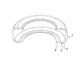
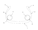
- FIG. 1 is a meridian cross-sectional view showing a pneumatic tire according to an embodiment of the present invention.
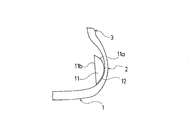
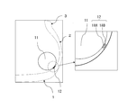
- FIG. 2 is a meridian cross-sectional view showing a state where the load support is removed from the pneumatic tire of FIG.
- FIG. 3 is a cross-sectional view showing a pair of hook-and-loop fasteners used as mechanical engagement tools in the pneumatic tire of FIG. 4 is a perspective sectional view showing the pneumatic tire of FIG.
- FIG. 5 is a perspective cross-sectional view showing a pneumatic tire provided with a load support that is intermittently arranged along the tire circumferential direction.
- FIG. 6 is a meridian cross-sectional view showing a run-flat running state of the pneumatic tire of FIG. FIG.
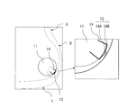
- FIG. 7 is a meridian cross-sectional view showing a main part of the pneumatic tire of FIG.
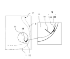
- FIG. 8 is a meridian cross-sectional view showing the main part of a pneumatic tire provided with load supports with different inner wall surface shapes.
- FIG. 9 is a meridian cross-sectional view showing the main part of a pneumatic tire having protrusions on the inner surface of the sidewall portion.
- FIG. 10 is a meridian cross-sectional view showing a run-flat running state of the pneumatic tire of FIG.
- FIG. 11 is a meridian cross-sectional view showing a pneumatic tire provided with a load support having a plurality of divided pieces divided in the tire radial direction.
- FIG. 12 is a meridian cross-sectional view showing a run-flat running state of the pneumatic tire of FIG.
- FIG. 13 is a cross-sectional view showing a main part of a pneumatic tire provided with another load support having a plurality of divided pieces divided in the tire radial direction.
- FIG. 14 is a cross-sectional view showing a main part of a pneumatic tire provided with still another load support having a plurality of divided pieces divided in the tire radial direction.
- FIG. 15 is a meridian cross-sectional view showing the main part of a pneumatic tire provided with a load support housed in a bag.
- FIG. 16 is a meridian cross-sectional view showing the main part of a pneumatic tire provided with another load support housed in a bag.
- FIG. 17 is a meridian cross-sectional view showing a pneumatic tire provided with a load support having a circular cross-sectional shape.
- 18 is a meridian cross-sectional view showing a run-flat running state of the pneumatic tire of FIG.
- FIG. 19 is a cross-sectional view showing a main part of a pneumatic tire using a pair of buttons as a mechanical engagement tool.
- FIG. 20 is a cross-sectional view showing a main part of another pneumatic tire using a pair of buttons as a mechanical engagement tool.
- FIG. 21 is a cross-sectional view showing the main part of still another pneumatic tire using a pair of buttons as a mechanical engagement tool.
- FIG. 22 is a cross-sectional view showing the main part of still another pneumatic tire using a pair of buttons as a mechanical engagement tool.
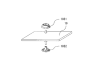
- FIG. 23 is a perspective view showing a state in which one button constituting the mechanical engagement tool is fixed to the sheet material.
- FIG. 24 is a perspective view showing a method of fixing one button constituting the mechanical engagement tool to the sheet material.
- FIG. 25 is a perspective view showing a method of fixing the other button constituting the mechanical engagement tool to the sheet material.
- FIG. 26 is a cross-sectional view showing a main part of a pneumatic tire using a pair of hook-and-loop fasteners as a mechanical engagement tool.
- FIG. 27 is a cross-sectional view showing a main part of another pneumatic tire using a pair of hook-and-loop fasteners as a mechanical engagement tool.
- FIG. 28 is a cross-sectional view showing the main part of still another pneumatic tire using a pair of hook-and-loop fasteners as mechanical engagement tools.
- FIG. 29 is a cross-sectional view showing a main part of still another pneumatic tire using a pair of hook-and-loop fasteners as mechanical engagement tools.
- FIG. 1 to 4 show a pneumatic tire according to an embodiment of the present invention.
- FIG. 1 the reinforcing structure of the pneumatic tire is depicted, but the reinforcing structure is not illustrated in other drawings.
- the pneumatic tire of this embodiment includes a tread portion 1 that extends in the tire circumferential direction and has an annular shape, and a pair of sidewall portions 2 that are disposed on both sides of the tread portion 1.
- a pair of bead portions 3 are provided inside the sidewall portions 2 in the tire radial direction.
- At least one carcass layer 4 is mounted between the pair of bead portions 3 and 3.
- the carcass layer 4 includes a plurality of carcass cords oriented in the tire radial direction.
- the carcass layer 4 is folded from the tire inner side to the outer side around the bead core 5 disposed in each bead portion 3.
- An organic fiber cord is preferably used as the carcass cord of the carcass layer 4.
- a plurality of belt layers 6 are embedded on the outer peripheral side of the carcass layer 4 in the tread portion 1.
- These belt layers 6 include a plurality of reinforcing cords inclined with respect to the tire circumferential direction, and are arranged so that the reinforcing cords cross each other between the layers.
- the inclination angle of the reinforcing cord with respect to the tire circumferential direction is set in a range of 10 ° to 40 °, for example.
- a steel cord is preferably used as the reinforcing cord of the belt layer 6.
- tire reinforcement structure mentioned above shows the typical example in a pneumatic tire, it is not limited to this.
- a load support 11 extending along the tire circumferential direction is disposed inside each sidewall portion 2.
- a load support 11 needs to be arranged at least inside the side wall part 2 on one side, but is preferably arranged inside the side wall parts 2 on both sides.
- the load support 11 is preferably continuous in the tire circumferential direction.
- the load support 11 is an annular body that is continuous in the tire circumferential direction, it can be inserted into a pneumatic tire by deforming it into an elliptical shape.
- the load support 11 is a small piece that is intermittently disposed along the tire circumferential direction, it can be easily inserted into the pneumatic tire.
- the load support 11 is made of rubber or resin.
- the JIS-A hardness is preferably in the range of 55 to 90.
- the melting point or thermal decomposition temperature of the resin is preferably 150 ° C. or higher. In other words, since the temperature of the load support 11 rises during run-flat travel, plastic deformation of the load support 11 can be prevented by using a resin having a melting point or a thermal decomposition temperature of 150 ° C. or higher.
- a thermosetting resin foam may be used.
- the load support 11 is detachably attached to the inner surface of the sidewall portion 2 via a mechanical engagement tool 12.
- the mechanical engagement tool 12 is a connecting means including a pair of engagement tools that enables mechanical engagement, and includes, for example, a pair of hook-and-loop fasteners and a pair of buttons. 1 to 4, a pair of hook-and-loop fasteners 13A and 13B (see FIG. 3) is used as the mechanical engagement tool 12.
- the hook-side hook-and-loop fastener 13A is fixed to the inner surface of the sidewall portion 2 by, for example, vulcanization bonding
- the loop-side hook-and-loop fastener 13B is fixed to the load support 11 by, for example, an adhesive. According to such a pair of hook-and-loop fasteners 13A and 13B, the load support 11 can be stably held during run-flat travel.
- a pair of surface fasteners 13A, shear shearing force in the engaged state of 13B is 0.6 kgf / cm 2 or more, more preferably, may is 0.7kgf / cm 2 ⁇ 2.5kgf / cm 2.
- the peel strength in the engaged state of the pair of hook-and-loop fasteners 13A and 13B is 200 gf / cm or more, and more preferably 250 gf / cm to 800 gf / cm.
- the load support 11 extending along the tire circumferential direction is disposed inside each sidewall portion 2, and the load support 11 is mechanically engaged with the inner surface of the sidewall portion 2. Since the pneumatic tire is punctured since it is mounted via the joint 12, the load support 11 is enveloped by the bent sidewall portion 2 as shown in FIG. Run flat running becomes possible. In particular, by performing vulcanization without applying a release agent to the tire inner surface during tire vulcanization, the frictional force of the load support 11 on the tire inner surface increases, and the stability of run-flat running can be improved.
- a side reinforcing layer made of a rubber composition is integrally formed inside the sidewall portion 2 as in the prior art. Compared to the case, it is possible to minimize the deterioration of rolling resistance and riding comfort during normal driving. That is, since the load support 11 mounted via the mechanical engagement tool 12 has little influence on the bending characteristics of the sidewall portion 2, the rolling resistance and riding comfort are not substantially deteriorated.
- the load support 11 is detachably attached to the inner surface of the sidewall portion 2 via the mechanical engagement tool 12, even if the load support 11 is damaged during the run flat running, the load support 11 The tire itself can be reused by exchanging only the body 11. Therefore, the pneumatic tire provided with the detachable load support 11 as described above is excellent in reusability after run-flat running.
- the above-described configuration can be applied to a pneumatic tire having a large flatness ratio, and there is an advantage that it is easy to manufacture a run-flat tire.
- the mechanical engagement tool 12 is disposed in a partial region of the surface where the load support 11 comes into contact with the inner surface of the sidewall portion 2 during run flat running. In other regions, a structure in which the load support 11 directly contacts the inner surface of the sidewall portion 2 without using the mechanical engagement tool 12 is employed. More specifically, the mechanical engagement tool 12 is selectively disposed only in a region outside the load support 11 in the tire radial direction. In this case, the contact area between the load support 11 and the sidewall portion 2 during normal traveling is reduced, and it is possible to effectively suppress deterioration in rolling resistance and riding comfort during normal traveling. However, even when the mechanical support 12 is disposed over the entire area where the load support 11 contacts the inner surface of the sidewall portion 2 during run-flat travel, rolling resistance and riding comfort during normal travel are improved. Is possible.
- the load support 11 includes an outer wall surface 11a (a wall surface on the outer side in the tire width direction) that contacts the inner surface of the sidewall portion 2 and an inner wall surface 11b (a wall surface on the inner side in the tire radial direction) that faces the tire lumen side.
- the inner wall surface 11b is preferably a flat surface (see FIG. 7) or a curved surface (see FIG. 8) that is recessed outward in the tire width direction.
- a force F that pushes the load support 11 toward the inner side in the tire width acts during run-flat travel, but by defining the shape of the inner wall surface 11b of the load support 11 as described above.
- the force F acting to push the load support 11 inward in the tire width direction during run-flat travel can be relaxed, and the load support 11 can be stably held during run-flat travel.
- the inner wall surface 11b is a curved surface that is recessed toward the outer side in the tire width direction, the load support 11 can be more stably held when the sidewall portion 2 is bent during run-flat travel.
- FIG. 9 and 10 show a pneumatic tire having protrusions on the inner surface of the sidewall portion.
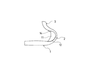
- a projection 14 is formed on the inner surface of the side wall portion 2 to lock the end portion of the load support 11 during run flat running.
- the edge part of the load support body 11 protrudes at the time of run-flat driving
- the load support 11 and 12 show a pneumatic tire provided with a load support having a plurality of divided pieces divided in the tire radial direction.
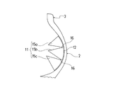
- the load support 11 has a plurality of divided pieces 15a, 15b, 15c divided in the tire radial direction, and these divided pieces 15a to 15c are in contact with each other during run-flat running.
- the divided pieces 15a to 15c are completely independent.
- Each of the divided pieces 15a to 15c is detachably attached to the inner surface of the sidewall portion 2 via the mechanical engagement tool 12.
- the load supporting body 11 composed of the divided pieces 15a to 15c is encased by the bent sidewall portion 2, and stable run-flat running is achieved. Is possible. In such a configuration, it is possible to ensure good durability by fixing the divided pieces 15a to 15c with the mechanical engagement tool 12, and moreover, as compared with the case where the load support 11 is integrated. Deterioration of rolling resistance and riding comfort during traveling can be suppressed.
- the hardness of the plurality of divided pieces 15a to 15c constituting the load support 11 may be constant, but may be different from each other as necessary. By making the hardness of the plurality of divided pieces 15a to 15c different from each other, it is possible to arbitrarily adjust the characteristics during run-flat running. For example, when the hardness of the plurality of divided pieces 15a to 15c is gradually reduced toward the inner side in the tire radial direction, durability during run-flat running can be improved.
- FIGS. 13 and 14 each show a pneumatic tire provided with another load support having a plurality of divided pieces divided in the tire radial direction.
- the divided pieces 15a to 15c constituting the load support 11 may be completely independent, but may be partially connected to each other as shown in FIG. 13 and FIG. Further, as shown in FIG. 14, it is preferable that the divided pieces 15 a to 15 c are connected to each other via the bending portion 16. Providing such a curved portion 16 makes it difficult for cracks to occur between the divided pieces 15a to 15c.
- FIGS. 15 and 16 each show a pneumatic tire provided with a load support housed in a bag.
- the load support 11 is accommodated in a bag 17, and the bag 17 is detachably attached to the inner surface of the sidewall portion 2 by a mechanical engagement tool 12.
- the load support 11 having a plurality of divided pieces 15 a to 15 c is accommodated in a bag 17, and the bag 17 is mechanically engaged with the inner surface of the sidewall portion 2 by the engagement tool 12. And is detachably mounted. Only a part of the load support body 11 (for example, an inner wall surface facing the tire lumen) is fixed to the bag body 17, and other parts are freely displaced with respect to the bag body 17. It is in a state that can be.
- the bag body 17 is constituted by a loop-side surface fastener, and the bag body 17 itself constitutes a part of the mechanical engagement tool.
- the load support 11 has a circular cross-sectional shape and is detachably attached to the inner surface of the sidewall portion 2 via a mechanical engagement tool 12.
- the load support 11 having a circular cross-sectional shape is mounted on the inner surface of the sidewall portion 2 as described above, when the pneumatic tire is punctured, the load is applied by the bent sidewall portion 2 as shown in FIG. Since the support body 11 is encased and the load support body 11 can be prevented from being compressed and damaged, stable run-flat travel is possible.
- the mechanical engagement tool 12 a pair of hook-and-loop fasteners, a pair of buttons, or the like can be used.
- buttons 18 ⁇ / b> A and 18 ⁇ / b> B are used as a mechanical engagement tool 12 for mounting the load support 11 on the inner surface of the sidewall portion 2.
- the button 18A is a male button
- the button 18B is a female button.
- One of the pair of buttons 18A and 18B is directly bonded to the load support 11, and the other is vulcanized and bonded to the tire inner surface.
- the buttons 18A and 18B that make a pair in this way are arranged at a plurality of locations in the tire circumferential direction.
- buttons 18 ⁇ / b> A and 18 ⁇ / b> B is used as the mechanical engagement tool 12, and one of the pair of buttons 18 ⁇ / b> A and 18 ⁇ / b> B is attached to the sheet material 19 bonded to the surface of the load support 11. It is fixed and the other is vulcanized and bonded to the tire inner surface. In this way, it is also possible to use one of the pair of buttons 18 ⁇ / b> A and 18 ⁇ / b> B while being fixed to the sheet material 19.
- buttons 18A and 18B are used as the mechanical engagement tool 12.
- One of the pair of buttons 18A and 18B is a sheet material 19 partially embedded in the load support 11. The other is vulcanized and bonded to the tire inner surface.
- only one end of the sheet material 19 is buried in the load support 11, and in the example of FIG. 22, both ends of the sheet material 19 are buried in the load support 11. ing.
- the load support 11 is formed of a foamed resin
- a part of the sheet material 19 is inserted into the foam mold, and foaming and curing is performed in a state including the sheet material 19, so that the load support 11 is formed.
- the sheet material 19 can be fixed with extremely high strength.
- FIG. 23 shows a state in which one button constituting the mechanical engagement tool is fixed to the sheet material
- FIG. 24 shows a method of fixing one button to the sheet material
- FIG. 25 shows the other button to the sheet material.
- the method of fixing to is shown.
- the button 18 ⁇ / b> B is fixed to the sheet material 19.
- the material of the sheet material 19 is not specifically limited, For example, a resin sheet, a rubber sheet, a fiber sheet (woven fabric, a knitted fabric, a nonwoven fabric), a fiber reinforced resin sheet, a fiber reinforced rubber sheet, etc. are used. As shown in FIG.
- the button 18B is composed of an engaging member 18B1 and a backing member 18B2, and the sheet material 19 is sandwiched between the engaging member 18B1 and the backing member 18B2, and both are swaged.
- the button 18B can be firmly fixed to the sheet material 19.
- the button 18A is composed of an engaging member 18A1 and a backing member 18A2, and both the sheet material 19 is sandwiched between the engaging member 18A1 and the backing member 18A2.
- the button 18A can be firmly fixed to the sheet material 19 by caulking.
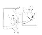
- FIGS. 26 to 29 each show a pneumatic tire using a pair of hook-and-loop fasteners as mechanical engagement tools.
- a pair of hook-and-loop fasteners 13 ⁇ / b> A and 13 ⁇ / b> B is used as a mechanical engagement tool 12 for mounting the load support 11 on the inner surface of the sidewall portion 2.
- the surface fastener 13A is a hook material
- the surface fastener 13B is a loop material.
- One of the pair of hook-and-loop fasteners 13A and 13B is fixed to the sheet material 19 partially embedded in the load support 11, and the other is vulcanized and bonded to the tire inner surface.
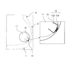
- FIG. 26 each show a pneumatic tire using a pair of hook-and-loop fasteners as mechanical engagement tools.
- a pair of hook-and-loop fasteners 13 ⁇ / b> A and 13 ⁇ / b> B is used as a mechanical engagement tool 12 for mounting the load support 11 on the inner surface of the
- a pair of hook-and-loop fasteners 13A and 13B is used as the mechanical engagement tool 12, but one of the pair of hook-and-loop fasteners 13A and 13B is partially in the load support 11. It is buried and the other is vulcanized and bonded to the tire inner surface.
- only one end of the hook-and-loop fastener 13B is buried in the load support 11, and in the example of FIG. 29, both ends of the hook-and-loop fastener 13B are buried in the load support 11. ing.
- the load support 11 is formed of foamed resin
- a part of the hook-and-loop fastener 13A or 13B is inserted into the foam mold and foamed and cured in a state including the hook-and-loop fastener 13A or 13B.
- the surface fastener 13A or 13B can be fixed to the support 11 with extremely high strength.
- a load support extending along the tire circumferential direction is disposed inside each sidewall portion, and the load support is machined against the inner surface of the sidewall portion.
- Tires of Examples 1 to 10 which were detachably mounted via a mechanical engagement tool were manufactured.
- As the mechanical engagement tool a pair of hook-and-loop fasteners having a shear shear force of 0.8 kgf / cm 2 and a peel strength of 400 gf / cm was used.
- a pair of buttons was used as another mechanical engagement tool.
- Such mechanical engagement tools were installed at a plurality of locations in the tire circumferential direction.
- a conventional tire in which a side reinforcing layer made of a rubber composition is integrally formed inside each sidewall portion was prepared. Further, a load support body extending along the tire circumferential direction was arranged inside each sidewall portion, and a tire of a comparative example in which the load support body was fixed to the inner surface of the sidewall portion with an adhesive was manufactured. .
- Run-flat mileage Each test tire is assembled to a wheel with a rim size of 18 ⁇ 8J and mounted on the test vehicle. The valve core of the right drive wheel is removed while the air pressure of the other tire is 230 kPa, and the test course consisting of asphalt road surface has an average speed of 80 km / h. The vehicle was run until the tire failed and the vehicle became unable to run, or the driver felt the vibration due to the tire failure, and the running distance was measured. It means that run flat durability is excellent, so that this mileage is large.
Landscapes
- Engineering & Computer Science (AREA)
- Mechanical Engineering (AREA)
- Tires In General (AREA)
Abstract
L'invention concerne un pneu tel que, même si un corps de support de charge est disposé sur chaque partie de paroi latérale, il est possible de réduire à un minimum la résistance au roulement et la détérioration du confort de conduite pendant un déplacement normal, ainsi que d'améliorer la réutilisation après un déplacement à plat. Ce pneu comporte : une partie bande de roulement (1) qui s'étend dans la direction circonférentielle du pneu et présente une forme annulaire ; une paire de parties de paroi latérale (2) qui sont agencées des deux côtés de la partie bande de roulement (1) ; une paire de parties talon (3) qui sont agencées sur l'intérieur des parties de paroi latérale (2) dans la direction radiale du pneu. Un corps de support de charge (11) s'étendant dans la direction circonférentielle du pneu est disposé sur l'intérieur de chacune des parties de paroi latérale (2). Le corps de support de charge (11) est monté de manière amovible sur la surface interne de la partie de paroi latérale (2) par un outil de mise en prise mécanique (2).
Priority Applications (4)
| Application Number | Priority Date | Filing Date | Title |
|---|---|---|---|
| US16/465,546 US11554616B2 (en) | 2016-11-30 | 2016-11-30 | Pneumatic tire with removably mounted run-flat load support bodies |
| PCT/JP2016/085547 WO2018100671A1 (fr) | 2016-11-30 | 2016-11-30 | Pneu |
| DE112016007492.1T DE112016007492B4 (de) | 2016-11-30 | 2016-11-30 | Luftreifen |
| CN201680090912.XA CN109952213B (zh) | 2016-11-30 | 2016-11-30 | 充气轮胎 |
Applications Claiming Priority (1)
| Application Number | Priority Date | Filing Date | Title |
|---|---|---|---|
| PCT/JP2016/085547 WO2018100671A1 (fr) | 2016-11-30 | 2016-11-30 | Pneu |
Publications (1)
| Publication Number | Publication Date |
|---|---|
| WO2018100671A1 true WO2018100671A1 (fr) | 2018-06-07 |
Family
ID=62242415
Family Applications (1)
| Application Number | Title | Priority Date | Filing Date |
|---|---|---|---|
| PCT/JP2016/085547 Ceased WO2018100671A1 (fr) | 2016-11-30 | 2016-11-30 | Pneu |
Country Status (4)
| Country | Link |
|---|---|
| US (1) | US11554616B2 (fr) |
| CN (1) | CN109952213B (fr) |
| DE (1) | DE112016007492B4 (fr) |
| WO (1) | WO2018100671A1 (fr) |
Citations (8)
| Publication number | Priority date | Publication date | Assignee | Title |
|---|---|---|---|---|
| JPH07304312A (ja) * | 1994-05-13 | 1995-11-21 | Bridgestone Corp | 空気入り安全タイヤ |
| JP2003094912A (ja) * | 2001-09-26 | 2003-04-03 | Bridgestone Corp | ランフラットタイヤ及びその製造方法 |
| JP2007098992A (ja) * | 2005-09-30 | 2007-04-19 | Sumitomo Rubber Ind Ltd | ランフラットタイヤ及びその製造方法 |
| JP2009061866A (ja) * | 2007-09-05 | 2009-03-26 | Yokohama Rubber Co Ltd:The | ランフラットタイヤ |
| JP2012025319A (ja) * | 2010-07-27 | 2012-02-09 | Yokohama Rubber Co Ltd:The | 空気入りタイヤおよびその製造方法 |
| WO2014088064A1 (fr) * | 2012-12-05 | 2014-06-12 | 横浜ゴム株式会社 | Pneumatique équipé d'un élément de fixation autoagrippant et procédé de fabrication dudit pneu |
| JP2015063171A (ja) * | 2013-09-24 | 2015-04-09 | 横浜ゴム株式会社 | 空気入りタイヤ |
| JP2015063170A (ja) * | 2013-09-24 | 2015-04-09 | 横浜ゴム株式会社 | 空気入りタイヤおよびその製造方法 |
Family Cites Families (11)
| Publication number | Priority date | Publication date | Assignee | Title |
|---|---|---|---|---|
| US4371023A (en) * | 1980-11-24 | 1983-02-01 | Aqualume, Incorporated | Tubeless tire with insert for preventing collapse in the event of loss of air pressure |
| TW564226B (en) * | 2003-02-18 | 2003-12-01 | Shuei-Jen Shiu | Enhanced method for manufacturing anti-puncturing tires |
| US20050115656A1 (en) * | 2003-11-28 | 2005-06-02 | Chin-Ming Hsieh | Safe tire with a supporting apparatus |
| JP4963878B2 (ja) * | 2006-06-06 | 2012-06-27 | 株式会社ブリヂストン | 空気入りランフラットラジアルタイヤ |
| EP2223813B1 (fr) * | 2007-11-14 | 2012-05-02 | Sumitomo Rubber Industries, Ltd. | Pneu à affaissement limité |
| JP4989449B2 (ja) * | 2007-12-25 | 2012-08-01 | 横浜ゴム株式会社 | 空気入りタイヤの製造方法及び空気入りタイヤ |
| JP5121589B2 (ja) * | 2008-06-11 | 2013-01-16 | 株式会社ブリヂストン | ランフラットタイヤ |
| US20150027607A1 (en) * | 2012-03-06 | 2015-01-29 | Smitiparna Satpathy | Multi- chambered tubeless tyre and method for producing |
| CN202847343U (zh) * | 2012-10-22 | 2013-04-03 | 北京化工大学 | 一种三角平衡轮廓充气轮胎 |
| CN105291717A (zh) * | 2014-07-25 | 2016-02-03 | 鸿富锦精密工业(深圳)有限公司 | 车轮 |
| EP3481625A4 (fr) * | 2016-07-06 | 2020-02-19 | Bridgestone Americas Tire Operations, LLC | Renforcement de stabilisation de paroi latérale post-vulcanisation et procédé de fabrication |
-
2016
- 2016-11-30 DE DE112016007492.1T patent/DE112016007492B4/de active Active
- 2016-11-30 CN CN201680090912.XA patent/CN109952213B/zh active Active
- 2016-11-30 WO PCT/JP2016/085547 patent/WO2018100671A1/fr not_active Ceased
- 2016-11-30 US US16/465,546 patent/US11554616B2/en active Active
Patent Citations (8)
| Publication number | Priority date | Publication date | Assignee | Title |
|---|---|---|---|---|
| JPH07304312A (ja) * | 1994-05-13 | 1995-11-21 | Bridgestone Corp | 空気入り安全タイヤ |
| JP2003094912A (ja) * | 2001-09-26 | 2003-04-03 | Bridgestone Corp | ランフラットタイヤ及びその製造方法 |
| JP2007098992A (ja) * | 2005-09-30 | 2007-04-19 | Sumitomo Rubber Ind Ltd | ランフラットタイヤ及びその製造方法 |
| JP2009061866A (ja) * | 2007-09-05 | 2009-03-26 | Yokohama Rubber Co Ltd:The | ランフラットタイヤ |
| JP2012025319A (ja) * | 2010-07-27 | 2012-02-09 | Yokohama Rubber Co Ltd:The | 空気入りタイヤおよびその製造方法 |
| WO2014088064A1 (fr) * | 2012-12-05 | 2014-06-12 | 横浜ゴム株式会社 | Pneumatique équipé d'un élément de fixation autoagrippant et procédé de fabrication dudit pneu |
| JP2015063171A (ja) * | 2013-09-24 | 2015-04-09 | 横浜ゴム株式会社 | 空気入りタイヤ |
| JP2015063170A (ja) * | 2013-09-24 | 2015-04-09 | 横浜ゴム株式会社 | 空気入りタイヤおよびその製造方法 |
Also Published As
| Publication number | Publication date |
|---|---|
| US20190283508A1 (en) | 2019-09-19 |
| CN109952213A (zh) | 2019-06-28 |
| DE112016007492T5 (de) | 2019-08-22 |
| CN109952213B (zh) | 2021-03-02 |
| DE112016007492B4 (de) | 2024-01-04 |
| US11554616B2 (en) | 2023-01-17 |
Similar Documents
| Publication | Publication Date | Title |
|---|---|---|
| JP4532520B2 (ja) | 面ファスナー付き空気入りタイヤ及びその製造方法 | |
| JP6728801B2 (ja) | 空気入りタイヤ | |
| JP4980621B2 (ja) | 取付パッチ構造及び空気入りタイヤ | |
| JP5530258B2 (ja) | 非空気圧タイヤ及びその製造方法 | |
| JP6094620B2 (ja) | 空気入りタイヤ | |
| WO2014088064A1 (fr) | Pneumatique équipé d'un élément de fixation autoagrippant et procédé de fabrication dudit pneu | |
| JP5809191B2 (ja) | 乗用車用のランフラットタイヤ | |
| JP5308906B2 (ja) | タイヤ内面への部材の貼付け方法 | |
| JP5809192B2 (ja) | 乗用車用のランフラットタイヤ | |
| CN106687306A (zh) | 充气轮胎 | |
| CN104507711A (zh) | 泄气保用轮胎 | |
| JP2022164929A (ja) | 乗用車用空気入りラジアルタイヤ | |
| CN109952213B (zh) | 充气轮胎 | |
| CN113543986A (zh) | 充气轮胎 | |
| JPH11320705A (ja) | 空気入りタイヤの製造方法 | |
| JP4039907B2 (ja) | ランフラットタイヤ及びタイヤホイール組立体 | |
| JP2019500268A (ja) | ラジアルカーカスまたはバイアスカーカスを有するタイヤ | |
| US10017009B2 (en) | Pneumatic tire | |
| JP5943152B2 (ja) | 空気入りタイヤ | |
| JP5087289B2 (ja) | ランフラットタイヤ及びランフラットタイヤとリムとの組立体 | |
| KR102388162B1 (ko) | 탈부착형 흡음재가 구비된 타이어 | |
| JP2006272992A (ja) | 空気入りタイヤ及びその製造方法 | |
| CN106457932A (zh) | 充气轮胎及其制造方法 | |
| JPH0781321A (ja) | 空気入りラジアルタイヤ | |
| JP4384098B2 (ja) | ランフラット支持体と空気入りタイヤとの固定具 |
Legal Events
| Date | Code | Title | Description |
|---|---|---|---|
| 121 | Ep: the epo has been informed by wipo that ep was designated in this application |
Ref document number: 16922571 Country of ref document: EP Kind code of ref document: A1 |
|
| 122 | Ep: pct application non-entry in european phase |
Ref document number: 16922571 Country of ref document: EP Kind code of ref document: A1 |
|
| NENP | Non-entry into the national phase |
Ref country code: JP |