WO2018100802A1 - Outil rotatif à percussion - Google Patents
Outil rotatif à percussion Download PDFInfo
- Publication number
- WO2018100802A1 WO2018100802A1 PCT/JP2017/028048 JP2017028048W WO2018100802A1 WO 2018100802 A1 WO2018100802 A1 WO 2018100802A1 JP 2017028048 W JP2017028048 W JP 2017028048W WO 2018100802 A1 WO2018100802 A1 WO 2018100802A1
- Authority
- WO
- WIPO (PCT)
- Prior art keywords
- impact
- rotation angle
- anvil
- impacts
- shut
- Prior art date
- Legal status (The legal status is an assumption and is not a legal conclusion. Google has not performed a legal analysis and makes no representation as to the accuracy of the status listed.)
- Ceased
Links
Images



Classifications
-
- B—PERFORMING OPERATIONS; TRANSPORTING
- B25—HAND TOOLS; PORTABLE POWER-DRIVEN TOOLS; MANIPULATORS
- B25B—TOOLS OR BENCH DEVICES NOT OTHERWISE PROVIDED FOR, FOR FASTENING, CONNECTING, DISENGAGING, OR HOLDING
- B25B21/00—Portable power-driven screw or nut setting or loosening tools; Attachments for drilling apparatus serving the same purpose
- B25B21/02—Portable power-driven screw or nut setting or loosening tools; Attachments for drilling apparatus serving the same purpose with means for imparting impact to screwdriver blade or nut socket
-
- B—PERFORMING OPERATIONS; TRANSPORTING
- B25—HAND TOOLS; PORTABLE POWER-DRIVEN TOOLS; MANIPULATORS
- B25B—TOOLS OR BENCH DEVICES NOT OTHERWISE PROVIDED FOR, FOR FASTENING, CONNECTING, DISENGAGING, OR HOLDING
- B25B23/00—Details of, or accessories for, spanners, wrenches, screwdrivers
- B25B23/14—Arrangement of torque limiters or torque indicators in wrenches or screwdrivers
Definitions
- the present invention relates to an impact rotary tool for tightening screw members such as bolts and nuts by intermittent rotational impact force.
- the mechanical impact rotary tool tightens the screw member by generating an intermittent rotational impact force on the output shaft when the hammer rotating with the motor output strikes the anvil in the rotation direction.
- an oil pulse tool which is a kind of impact rotary tool, causes an intermittent rotational impact force to be generated on an output shaft by a liner that rotates with motor output creating a pressure difference between oil chambers, thereby tightening a screw member. Since the impact rotary tool is used in an assembly factory or the like, the tightening torque of the screw member needs to be accurately controlled so as to be a value set by the user.
- Patent Document 1 counts the number of hits detected by the impact detection means and the number of hits detected by the hit detection means, and the counted number of hits corresponds to the number of hits corresponding to the tightening torque set by the user.
- the part where the bolt was fastened first sinks relatively, so that the part where the bolt is fastened later from the original state Slightly tilted.
- the impact rotary tool may start hitting by the impact mechanism before the bolt is seated by receiving a load due to the tilt of the fastened member.
- the impact rotary tool is not affected by the impact mechanism before the bolt is seated. May start hitting.
- shutoff impact number the number of impacts (impacts) corresponding to the tightening torque value set by the user. Since the number of strikes is digested by the load, the tightening torque value of the bolt after tightening may not reach the tightening torque value set by the user.
- the present invention has been made in view of such circumstances, and an object of the present invention is to provide a technique for appropriately correcting the shut-off impact number so as to fasten a screw member with a tightening torque value set by a user.
- an impact rotary tool includes an impact mechanism that generates an intermittent rotational impact force on an anvil by a motor output, and a setting unit that sets the number of shut-off impacts of the impact mechanism.
- An impact detection unit that detects the impact applied to the anvil by the impact mechanism, and a control that counts the number of impacts detected by the impact detection unit and stops the rotation of the motor when the counted number of impacts reaches the shut-off impact number
- a rotation angle acquisition unit that acquires an anvil rotation angle due to a single impact of the impact mechanism. The control unit corrects the set shut-off impact number based on the impact number when the anvil rotation angle acquired by the rotation angle acquisition unit becomes a predetermined threshold value or falls below the predetermined threshold value.
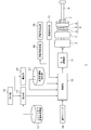
- FIG. 1 shows a configuration of a mechanical impact rotary tool according to an embodiment of the present invention.
- the impact rotary tool 1 electric power is supplied by a rechargeable battery built in the battery pack.
- the motor 2 as a driving source is driven by the motor driving unit 11, and the rotation output of the motor 2 is decelerated by the speed reducer 3 and transmitted to the drive shaft 5.
- a hammer 6 is connected to the drive shaft 5 via a cam mechanism (not shown), and the hammer 6 is urged toward the anvil 7 including the output shaft 8 by the spring 4.
- the hammer 6 and the anvil 7 are engaged in the rotation direction, and the hammer 6 transmits the rotation of the drive shaft 5 to the anvil 7.
- the hammer 6 moves backward against the spring 4 by the cam mechanism, and the engagement state between the hammer 6 and the anvil 7 is released.
- the hammer 6 advances while rotating by an urging force by the spring 4 and a guidance by the cam mechanism, and strikes the anvil 7 in the rotational direction.
- the spring 4 the drive shaft 5, the hammer 6, and the cam mechanism strike the anvil 7 and the output shaft 8 by the motor output to generate intermittent rotational impact force on the anvil 7 and the output shaft 8.
- the impact mechanism 9 is configured.
- the configuration of the control unit 10, the setting unit 15, the rotation angle acquisition unit 19, the derivation unit 20, and the like are realized by a microcomputer or the like mounted on the control board.
- the control unit 10 has a function of controlling the rotation of the motor 2.
- the operation switch 16 is a trigger switch operated by a user, and the control unit 10 controls on / off of the motor 2 by operating the operation switch 16 and drives a drive according to the operation amount of the operation switch 16.
- the motor drive unit 11 controls the voltage applied to the motor 2 according to the drive instruction supplied from the control unit 10 to adjust the motor rotation speed.
- the impact detector 12 detects an impact applied to the anvil 7 by the impact mechanism 9.
- the impact detection unit 12 may include an impact sensor that detects an impact caused by the hammer 6 hitting the anvil 7, and an amplifier that amplifies the output of the impact sensor and supplies the amplified output to the control unit 10.
- the impact sensor is a piezoelectric shock sensor and outputs a voltage signal corresponding to the impact, and the amplifier amplifies the output voltage signal and supplies the amplified voltage signal to the control unit 10.
- the impact detection unit 12 may adopt another configuration, and may be a sound sensor that detects an impact applied to the anvil 7 by the impact mechanism 9 by detecting an impact sound, for example.
- the rotation angle detector 18 detects the rotation angle of the motor 2 and / or the anvil 7.
- the rotation angle detection unit 18 may be a magnetic rotary encoder that detects the rotation angle of the motor 2.
- the rotation angle detection unit 18 supplies a motor rotation angle detection signal to the rotation angle acquisition unit 19.
- the rotation angle acquisition unit 19 has a function of acquiring the rotation angle of the anvil 7 from the motor rotation angle detection signal.
- the rotation angle acquisition unit 19 acquires the angle at which the anvil 7 rotates for each impact by the impact mechanism 9.
- the angle at which the anvil 7 rotates by a single impact is simply referred to as “anvil rotation angle”.
- the hammer 6 has a pair of hammer claws 6a and 6b erected from the front surface, and the anvil 7 has a pair of anvil claws 7a and 7b extending in the radial direction from the center.
- FIG. 2A shows a state in which the hammer claw and the anvil claw are engaged in the circumferential direction.
- the hammer claw 6a and the hammer claw 6b engage with the anvil claw 7a and the anvil claw 7b, respectively, and apply a rotational force in the direction indicated by the arrow A.
- FIG. 2B shows a state in which the engagement state between the hammer claw and the anvil claw is released.
- FIG. 2C shows a state in which the hammer claw hits the anvil claw and rotates the anvil 7.
- the rotation angle acquisition unit 19 can acquire the anvil rotation angle ⁇ per impact from the motor rotation angle ⁇ between impacts using the following Equation 1.
- the rotation angle acquisition unit 19 is notified from the control unit 10 that there has been an impact by the impact mechanism 9, and the rotation angle acquisition unit 19 receives the motor rotation angle ⁇ between the impacts from the motor rotation angle detection signal at the notified timing.
- ⁇ indicates a reduction ratio by the reduction gear 3.
- the rotation angle acquisition unit 19 can acquire the anvil rotation angle ⁇ by a single impact using the motor rotation angle ⁇ between the impacts, but the acquisition accuracy of the anvil rotation angle ⁇ depends on the detection accuracy of the motor rotation angle ⁇ . .
- the anvil rotation angle ⁇ gradually decreases with each impact, but if the detection accuracy of the motor rotation angle ⁇ is low, the anvil rotation angle ⁇ is calculated to be larger than the anvil rotation angle due to the previous impact. Can also occur. Therefore, the rotation angle acquisition unit 19 may acquire the anvil rotation angle ⁇ due to one impact by performing a moving average process on the K anvil rotation angles due to consecutive K impacts. By performing the moving average process, the rotation angle acquisition unit 19 can acquire the anvil rotation angle ⁇ with high reliability.
- the rotation angle acquisition unit 19 acquires the anvil rotation angle ⁇ from the motor rotation angle detection signal, but in another example, the rotation angle detection unit 18 may directly detect the rotation angle of the anvil 7. At this time, the rotation angle acquisition unit 19 can acquire the anvil rotation angle ⁇ between impacts based on the anvil rotation angle detection signal supplied from the rotation angle detection unit 18.
- target torque value a target tightening torque value (hereinafter, also simply referred to as “target torque value”) corresponding to the work target to the impact rotary tool 1 before starting the work.
- target torque value a target tightening torque value
- the impact rotary tool 1 counts the number of impacts detected by the impact detection unit 12, and when the counted number of impacts reaches the number of impacts (shutoff impact number) corresponding to the target torque value, Executes a shut-off function that automatically stops rotation.
- the shut-off impact number storage unit 17 stores the shut-off impact number corresponding to each set value of the target torque.
- the shut-off impact number storage unit 17 stores a shut-off impact number corresponding to each set value of, for example, 30 steps. This means that the user can select one of the 30-step tightening torque values according to the work target.
- the shut-off impact number storage unit 17 may be configured as a master table, and the stored content may not be updated.
- the setting unit 15 has a function of setting the shut-off impact number of the impact mechanism 9 with reference to the stored contents of the shut-off impact number storage unit 17.
- FIG. 3 shows the correspondence between the target torque value stored in the shut-off impact number storage unit 17 and the shut-off impact number.
- the setting unit 15 refers to the storage content of the shut-off impact number storage unit 17 and sets the shut-off impact number to “64 times”.
- the shut-off impact number storage unit 17 only needs to store information or data for the setting unit 15 to derive the shut-off impact number corresponding to the target torque value. For example, the shut-off impact number is calculated from the target torque value. You may memorize
- the accepting unit 14 accepts an operation input by the user and supplies it to the setting unit 15.
- the reception unit 14 includes a wireless communication module, and the user inputs an operation to the impact rotary tool 1 using a remote controller attached to the tool.
- the tool body may be provided with operation buttons and a touch panel, and the receiving unit 14 may receive an operation input by the user.
- the user selects a target torque value using the remote controller.
- the setting unit 15 refers to the stored contents of the shut-off impact number storage unit 17 to derive the shut-off impact number corresponding to the target torque value, and the control unit 10 To supply.
- the setting unit 15 derives the shut-off shock number and supplies the shut-off shock number to the control unit 10, and the control unit 10 makes the shut-off shock number available for rotation control of the motor 2. This is called the setting process.
- the control unit 10 monitors the output voltage of the impact detection unit 12, and if the output voltage of the impact detection unit 12 exceeds the impact determination voltage Vth, intermittent impact force is applied to the anvil 7 by the impact mechanism 9. Determine that it has occurred. When determining that the rotational impact force has occurred, the control unit 10 notifies the rotation angle acquisition unit 19 of the determination result.
- the control unit 10 includes a comparator that compares the output voltage of the impact detection unit 12 and the impact determination voltage Vth, and may determine from the output of the comparator that an intermittent rotational impact force has occurred in the anvil 7. .
- the control unit 10 counts the number of impacts detected by the impact detection unit 12.
- the control unit 10 automatically stops the rotation of the motor 2 when the counted number of impacts becomes the number of shut-off impacts. At this time, the tightening torque value of the screw member needs to be a target torque value set by the user.
- a load of a predetermined value or more (hereinafter also referred to as “intermediate load”) is applied between the hammer 6 and the anvil 7.
- intermediate load a load of a predetermined value or more
- the control unit 10 stops the rotation of the motor 2 with the number of shut-off impacts, since the number of impacts (impacts) is digested by a midway load, the tightening torque value of the bolt after fastening is determined by the user. The set target torque value is not reached. Therefore, the control unit 10 according to the embodiment has a function of appropriately correcting the number of shut-off shocks set by the setting unit 15 when a load occurs midway.
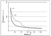
- FIG. 4 is a diagram showing the relationship between the anvil rotation angle and the number of impacts.
- the manufacturer of the impact rotary tool 1 also measures the relationship between the anvil rotation angle and the number of impacts when measuring the number of shut-off impacts for realizing a plurality of tightening torque values.
- the relationship between the anvil rotation angle and the number of impacts is stored in a storage unit (not shown). If there is no midway load, as shown in line L1, for a while after the start of hitting, the anvil rotation angle greatly decreases for each hit, and then the rate of decrease of the anvil rotation angle for each hit is There is a tendency to become smaller.
- FIG. 5 is a diagram for comparing the relationship between the anvil rotation angle and the number of impacts.
- Line L2 shows the relationship between the anvil rotation angle and the number of impacts acquired when there is an intermediate load before the screw member is seated.
- the impact mechanism 9 when a midway load exists, the impact mechanism 9 generates a hit against the midway load, so that the number of impacts is already digested when the screw member is seated.
- the number of impacts digested with respect to the midway load is “n times”, as shown in FIG. 3, when the number of shutoff impacts is set to “64 times”, the number of impacts after the screw member is seated is (64-n) times, and the tightening torque value may be less than the target torque value.
- the control unit 10 performs the process of correcting the shut-off impact number set by the setting unit 15 by adding the number of impacts digested by the midway load to the shut-off impact number.
- the control unit 10 uses a predetermined threshold value of the anvil rotation angle.
- the control unit 10 performs the shutoff impact set by the setting unit 15 based on the number of impacts when the anvil rotation angle acquired by the rotation angle acquisition unit 19 becomes a predetermined threshold or falls below the predetermined threshold. Correct the number.
- FIG. 6 shows the threshold value Th set for the anvil rotation angle.
- the threshold value Th is set to an anvil rotation angle corresponding to a load larger than the midway load. That is, when the anvil rotation angle acquired by the rotation angle acquisition unit 19 becomes the threshold value Th or falls below the threshold value Th, the screw member is already seated and is in a state of being tightened.
- a threshold Th is set.
- the threshold Th may be set as a default value, but may be set by the user using a remote controller.
- the reference impact number storage unit 21 stores the number of impacts until the anvil rotation angle due to one impact becomes the threshold Th.
- this number of impacts is referred to as “reference impact number”.
- the reference impact number until the anvil rotation angle reaches the threshold Th is N1. This indicates that the anvil rotation angle becomes the threshold value Th when the number of impacts is N1 when there is no load on the way.
- the derivation unit 20 derives the reference impact number N1 from the relationship between the anvil rotation angle and the impact number shown in FIG. Thus, it may be stored in the reference impact number storage unit 21.
- the controller 10 calculates the difference (N2 ⁇ N1) between the reference impact number N1 and the actual impact number N2 as the corrected impact number.
- This corrected number of impacts corresponds to the number of impacts digested in order to overcome the midway load until the actual anvil rotation angle reaches the threshold value Th. Therefore, the control unit 10 corrects the shut-off impact number based on the calculated corrected impact number. Specifically, the control unit 10 corrects the shut-off impact number by adding the corrected impact number to the shut-off impact number.
- line L3 is obtained by translating line L1 to the right by the number of corrected impacts.
- the screw member is already seated and tightened, so the anvil rotation angle indicated by the line L2 is in accordance with the relationship indicated by the line L3 due to the impact after the impact number N2. It will change substantially.
- the threshold value Th for the anvil rotation angle is preferably set so that the reference impact number N1 is a predetermined value or more.
- the threshold Th is preferably set so that the reference impact number is K or more.
- the anvil rotation angle tends to decrease greatly for a while after the hitting is started, and thereafter, the reduction rate tends to decrease.
- the threshold value Th may be set to an anvil rotation angle when the decrease rate of the anvil rotation angle becomes a predetermined value or less.
- the control unit 10 corrects the shut-off impact number based on the impact number N2 when the anvil rotation angle becomes the threshold value Th or falls below the threshold value Th.
- the control unit 10 preferably continues without stopping the rotation of the motor 2 when the anvil rotation angle has not yet reached the threshold Th.
- Such a situation can occur, for example, when there is an intermediate load over the entire length of the bolt or when the number of shut-off impacts is set to be small.
- the control unit 10 continues the rotation of the motor 2 even after reaching the shut-off impact number, calculates the corrected impact number when the anvil rotation angle reaches or falls below the threshold Th, and performs the shut-off impact. The number is corrected, and the rotation of the motor 2 is controlled with the corrected number of shut-off shocks.
- the impact rotary tool 1 of the embodiment includes the motor 2 that is an electric motor as a drive source, other types of motors such as an air motor may be mounted.
- the impact rotary tool 1 of the embodiment is a mechanical rotary tool, but may be another type of impact rotary tool, for example, an oil pulse tool.
- An impact rotary tool (1) includes an impact mechanism (9) that generates an intermittent rotational impact force on an anvil (7) by a motor output, and a setting unit that sets the number of shut-off impacts of the impact mechanism.
- the impact detection unit (12) for detecting the impact applied to the anvil by the impact mechanism, and the number of impacts detected by the impact detection unit are counted, and the counted number of impacts becomes the shut-off impact number.
- a control unit (10) for stopping the rotation of the motor and a rotation angle acquisition unit (19) for acquiring an anvil rotation angle by one impact of the impact mechanism are provided.
- the control unit (10) sets the setting unit (15) based on the number of impacts when the anvil rotation angle acquired by the rotation angle acquisition unit (19) becomes a predetermined threshold Th or falls below the predetermined threshold Th. ) Correct the number of shut-off shocks set by (1).
- the impact rotating tool (1) may further include a reference impact number storage unit (21) for storing a reference impact number until the anvil rotation angle due to one impact becomes a predetermined threshold value.
- the control unit (10) is a corrected impact number that is a difference between the reference impact number and the impact number when the anvil rotation angle acquired by the rotation angle acquisition unit becomes a predetermined threshold value or falls below the predetermined threshold value. Based on the above, the shut-off impact number may be corrected. At this time, the control unit (10) may correct the shut-off impact number by adding the corrected impact number to the shut-off impact number.
- the predetermined threshold value of the anvil rotation angle is preferably set so that the reference impact number is equal to or greater than a predetermined value.
- the rotation angle acquisition unit (19) may acquire the anvil rotation angle due to one impact by performing a moving average process on the K anvil rotation angles due to the continuous K impacts.
- the predetermined threshold value of the anvil rotation angle is preferably set so that the reference impact number is K or more.
- the present invention can be used for tools such as impact rotary tools.
Landscapes
- Engineering & Computer Science (AREA)
- Mechanical Engineering (AREA)
- Details Of Spanners, Wrenches, And Screw Drivers And Accessories (AREA)
Abstract
Selon l'invention, une unité de réglage (15) règle un nombre de percussions pour l'arrêt d'un mécanisme de percussion (9). Une unité de détection de percussion (12) détecte les percussions appliquées à une enclume (7) par le mécanisme de percussion (9). Une unité de commande (10) compte le nombre de percussions détectées par l'unité de détection de percussion (12) et arrête la rotation d'un moteur lorsque le nombre compté de percussions atteint le nombre de percussions pour l'arrêt. Une unité d'acquisition d'angle de rotation (19) acquiert l'angle de rotation d'enclume dû à une percussion du mécanisme de percussion (9). L'unité de commande (10) corrige le nombre de percussion pour l'arrêt réglé par l'unité de réglage (15), sur la base du nombre de percussions lorsque l'angle de rotation d'enclume acquis par l'unité d'acquisition d'angle de rotation (19) a atteint une valeur de seuil prescrite ou est inférieur à la valeur de seuil prescrite.
Applications Claiming Priority (2)
| Application Number | Priority Date | Filing Date | Title |
|---|---|---|---|
| JP2016232440A JP6646858B2 (ja) | 2016-11-30 | 2016-11-30 | インパクト回転工具 |
| JP2016-232440 | 2016-11-30 |
Publications (1)
| Publication Number | Publication Date |
|---|---|
| WO2018100802A1 true WO2018100802A1 (fr) | 2018-06-07 |
Family
ID=62242354
Family Applications (1)
| Application Number | Title | Priority Date | Filing Date |
|---|---|---|---|
| PCT/JP2017/028048 Ceased WO2018100802A1 (fr) | 2016-11-30 | 2017-08-02 | Outil rotatif à percussion |
Country Status (2)
| Country | Link |
|---|---|
| JP (1) | JP6646858B2 (fr) |
| WO (1) | WO2018100802A1 (fr) |
Cited By (5)
| Publication number | Priority date | Publication date | Assignee | Title |
|---|---|---|---|---|
| US11951596B2 (en) | 2020-08-05 | 2024-04-09 | Milwaukee Electric Tool Corporation | Rotary impact tool |
| US12076841B2 (en) | 2020-07-31 | 2024-09-03 | Panasonic Intellectual Property Management Co., Ltd. | Impact tool, method for controlling the impact tool, and program |
| US12240085B2 (en) | 2020-06-04 | 2025-03-04 | Milwaukee Electric Tool Corporation | Systems and methods for detecting anvil position using an inductive sensor |
| US12251800B2 (en) | 2020-06-17 | 2025-03-18 | Milwaukee Electric Tool Corporation | Systems and methods for detecting anvil position using a relief feature |
| US12528170B2 (en) | 2023-04-25 | 2026-01-20 | Milwaukee Electric Tool Corporation | Impact tool anvil with improved durability |
Citations (7)
| Publication number | Priority date | Publication date | Assignee | Title |
|---|---|---|---|---|
| EP1000710A1 (fr) * | 1998-11-16 | 2000-05-17 | Renault | Procédé de mesure et/ou de commande d'un équipement de vissage comprenant une visseuse hydropneumatique à martèlement |
| JP2001246573A (ja) * | 2000-03-03 | 2001-09-11 | Matsushita Electric Works Ltd | インパクト締め付け工具 |
| JP2006015438A (ja) * | 2004-06-30 | 2006-01-19 | Matsushita Electric Works Ltd | インパクト締め付け工具 |
| JP2006231446A (ja) * | 2005-02-23 | 2006-09-07 | Matsushita Electric Works Ltd | インパクト締付け工具 |
| JP2008213089A (ja) * | 2007-03-02 | 2008-09-18 | Matsushita Electric Works Ltd | 回転式工具 |
| US20090250233A1 (en) * | 2006-08-02 | 2009-10-08 | Paul William Wallace | Method and apparatus for determining when a threaded fastener has been tightened to a predetermined tightness |
| JP2013107165A (ja) * | 2011-11-21 | 2013-06-06 | Panasonic Eco Solutions Power Tools Co Ltd | インパクト回転工具 |
-
2016
- 2016-11-30 JP JP2016232440A patent/JP6646858B2/ja active Active
-
2017
- 2017-08-02 WO PCT/JP2017/028048 patent/WO2018100802A1/fr not_active Ceased
Patent Citations (7)
| Publication number | Priority date | Publication date | Assignee | Title |
|---|---|---|---|---|
| EP1000710A1 (fr) * | 1998-11-16 | 2000-05-17 | Renault | Procédé de mesure et/ou de commande d'un équipement de vissage comprenant une visseuse hydropneumatique à martèlement |
| JP2001246573A (ja) * | 2000-03-03 | 2001-09-11 | Matsushita Electric Works Ltd | インパクト締め付け工具 |
| JP2006015438A (ja) * | 2004-06-30 | 2006-01-19 | Matsushita Electric Works Ltd | インパクト締め付け工具 |
| JP2006231446A (ja) * | 2005-02-23 | 2006-09-07 | Matsushita Electric Works Ltd | インパクト締付け工具 |
| US20090250233A1 (en) * | 2006-08-02 | 2009-10-08 | Paul William Wallace | Method and apparatus for determining when a threaded fastener has been tightened to a predetermined tightness |
| JP2008213089A (ja) * | 2007-03-02 | 2008-09-18 | Matsushita Electric Works Ltd | 回転式工具 |
| JP2013107165A (ja) * | 2011-11-21 | 2013-06-06 | Panasonic Eco Solutions Power Tools Co Ltd | インパクト回転工具 |
Cited By (7)
| Publication number | Priority date | Publication date | Assignee | Title |
|---|---|---|---|---|
| US12240085B2 (en) | 2020-06-04 | 2025-03-04 | Milwaukee Electric Tool Corporation | Systems and methods for detecting anvil position using an inductive sensor |
| US12251800B2 (en) | 2020-06-17 | 2025-03-18 | Milwaukee Electric Tool Corporation | Systems and methods for detecting anvil position using a relief feature |
| US12654295B2 (en) | 2020-06-17 | 2026-06-16 | Milwaukee Electric Tool Corporation | Systems and methods for detecting anvil position using a relief feature |
| US12076841B2 (en) | 2020-07-31 | 2024-09-03 | Panasonic Intellectual Property Management Co., Ltd. | Impact tool, method for controlling the impact tool, and program |
| US11951596B2 (en) | 2020-08-05 | 2024-04-09 | Milwaukee Electric Tool Corporation | Rotary impact tool |
| US12583083B2 (en) | 2020-08-05 | 2026-03-24 | Milwaukee Electric Tool Corporation | Rotary impact tool |
| US12528170B2 (en) | 2023-04-25 | 2026-01-20 | Milwaukee Electric Tool Corporation | Impact tool anvil with improved durability |
Also Published As
| Publication number | Publication date |
|---|---|
| JP2018089705A (ja) | 2018-06-14 |
| JP6646858B2 (ja) | 2020-02-14 |
Similar Documents
| Publication | Publication Date | Title |
|---|---|---|
| JP7170290B2 (ja) | インパクト回転工具 | |
| US10919134B2 (en) | Impact rotary tool | |
| JP4412377B2 (ja) | インパクト回転工具 | |
| JP6646858B2 (ja) | インパクト回転工具 | |
| US9701000B2 (en) | Impact rotation tool and impact rotation tool attachment | |
| JP3903976B2 (ja) | 締付け工具 | |
| US20160325414A1 (en) | Method for measuring inertia moment of impact rotary tool and impact rotary tool using measuring method | |
| US20130153252A1 (en) | Impact tightening tool | |
| US10926386B2 (en) | Impact rotary tool | |
| JP2005118910A (ja) | インパクト回転工具 | |
| EP2895300B1 (fr) | Outil de serrage à impact | |
| JP6782428B2 (ja) | インパクト回転工具 | |
| JP2009083002A (ja) | インパクト回転工具 | |
| JP2013107165A (ja) | インパクト回転工具 | |
| JP6664102B2 (ja) | インパクト回転工具およびシャットオフ衝撃数の設定方法 | |
| US20190275650A1 (en) | Electric pulse tool | |
| JP2006015438A (ja) | インパクト締め付け工具 | |
| JP7325001B2 (ja) | インパクト回転工具 | |
| JP6913870B2 (ja) | インパクト回転工具 | |
| JP2006231445A (ja) | インパクト締付け工具 |
Legal Events
| Date | Code | Title | Description |
|---|---|---|---|
| 121 | Ep: the epo has been informed by wipo that ep was designated in this application |
Ref document number: 17877216 Country of ref document: EP Kind code of ref document: A1 |
|
| NENP | Non-entry into the national phase |
Ref country code: DE |
|
| 122 | Ep: pct application non-entry in european phase |
Ref document number: 17877216 Country of ref document: EP Kind code of ref document: A1 |