WO2018105169A1 - Dispositif et procédé d'analyse de gaz - Google Patents
Dispositif et procédé d'analyse de gaz Download PDFInfo
- Publication number
- WO2018105169A1 WO2018105169A1 PCT/JP2017/029279 JP2017029279W WO2018105169A1 WO 2018105169 A1 WO2018105169 A1 WO 2018105169A1 JP 2017029279 W JP2017029279 W JP 2017029279W WO 2018105169 A1 WO2018105169 A1 WO 2018105169A1
- Authority
- WO
- WIPO (PCT)
- Prior art keywords
- gas
- sample gas
- moisture
- line
- concentration
- Prior art date
- Legal status (The legal status is an assumption and is not a legal conclusion. Google has not performed a legal analysis and makes no representation as to the accuracy of the status listed.)
- Ceased
Links
Images


Classifications
-
- G—PHYSICS
- G01—MEASURING; TESTING
- G01N—INVESTIGATING OR ANALYSING MATERIALS BY DETERMINING THEIR CHEMICAL OR PHYSICAL PROPERTIES
- G01N31/00—Investigating or analysing non-biological materials by the use of the chemical methods specified in the subgroup; Apparatus specially adapted for such methods
- G01N31/10—Investigating or analysing non-biological materials by the use of the chemical methods specified in the subgroup; Apparatus specially adapted for such methods using catalysis
-
- G—PHYSICS
- G01—MEASURING; TESTING
- G01M—TESTING STATIC OR DYNAMIC BALANCE OF MACHINES OR STRUCTURES; TESTING OF STRUCTURES OR APPARATUS, NOT OTHERWISE PROVIDED FOR
- G01M15/00—Testing of engines
- G01M15/04—Testing internal-combustion engines
- G01M15/10—Testing internal-combustion engines by monitoring exhaust gases or combustion flame
- G01M15/102—Testing internal-combustion engines by monitoring exhaust gases or combustion flame by monitoring exhaust gases
-
- G—PHYSICS
- G01—MEASURING; TESTING
- G01N—INVESTIGATING OR ANALYSING MATERIALS BY DETERMINING THEIR CHEMICAL OR PHYSICAL PROPERTIES
- G01N1/00—Sampling; Preparing specimens for investigation
-
- G—PHYSICS
- G01—MEASURING; TESTING
- G01N—INVESTIGATING OR ANALYSING MATERIALS BY DETERMINING THEIR CHEMICAL OR PHYSICAL PROPERTIES
- G01N1/00—Sampling; Preparing specimens for investigation
- G01N1/02—Devices for withdrawing samples
- G01N1/22—Devices for withdrawing samples in the gaseous state
-
- G—PHYSICS
- G01—MEASURING; TESTING
- G01N—INVESTIGATING OR ANALYSING MATERIALS BY DETERMINING THEIR CHEMICAL OR PHYSICAL PROPERTIES
- G01N33/00—Investigating or analysing materials by specific methods not covered by groups G01N1/00 - G01N31/00
- G01N33/0004—Gaseous mixtures, e.g. polluted air
- G01N33/0009—General constructional details of gas analysers, e.g. portable test equipment
- G01N33/0011—Sample conditioning
- G01N33/0016—Sample conditioning by regulating a physical variable, e.g. pressure or temperature
-
- G—PHYSICS
- G01—MEASURING; TESTING
- G01N—INVESTIGATING OR ANALYSING MATERIALS BY DETERMINING THEIR CHEMICAL OR PHYSICAL PROPERTIES
- G01N33/00—Investigating or analysing materials by specific methods not covered by groups G01N1/00 - G01N31/00
- G01N33/0004—Gaseous mixtures, e.g. polluted air
- G01N33/0009—General constructional details of gas analysers, e.g. portable test equipment
- G01N33/0022—General constructional details of gas analysers, e.g. portable test equipment using a number of analysing channels
- G01N33/0024—General constructional details of gas analysers, e.g. portable test equipment using a number of analysing channels a chemical reaction taking place or a gas being eliminated in one or more channels
-
- G—PHYSICS
- G01—MEASURING; TESTING
- G01N—INVESTIGATING OR ANALYSING MATERIALS BY DETERMINING THEIR CHEMICAL OR PHYSICAL PROPERTIES
- G01N33/00—Investigating or analysing materials by specific methods not covered by groups G01N1/00 - G01N31/00
- G01N33/0004—Gaseous mixtures, e.g. polluted air
- G01N33/0009—General constructional details of gas analysers, e.g. portable test equipment
- G01N33/0027—General constructional details of gas analysers, e.g. portable test equipment concerning the detector
- G01N33/0036—General constructional details of gas analysers, e.g. portable test equipment concerning the detector specially adapted to detect a particular component
- G01N33/0047—Organic compounds
Definitions
- the present invention relates to a gas analyzer and a gas analysis method for analyzing sample gas such as exhaust gas discharged from an internal combustion engine.
- This type of gas analyzer is configured to measure methane and other hydrocarbons contained in the exhaust gas using an oxidation catalyst called a non-methane cutter for removing hydrocarbons other than methane from the exhaust gas. There is something.
- methane transmission efficiency methane transmission efficiency
- ethane transmission efficiency transmission efficiency of ethane
- the specific required levels are, for example, methane permeation efficiency of 85% or more and ethane permeation efficiency of 2% or less. The resolution which becomes is mentioned.
- the gas analyzer described in Patent Document 1 is configured so that moisture can be added to the non-methane cutter in order to improve the separation ability of the non-methane cutter, and thereby, the methane in the non-methane cutter can be added. Combustion is suppressed and methane permeation efficiency is improved.
- the addition of moisture suppresses the combustion of ethane and improves the ethane permeation efficiency. Therefore, in order to ensure the separability of the non-methane cutter to the required level, the amount of water supplied to the non-methane cutter is reduced. It needs to be adjusted.
- Patent Document 1 moisture contained in the exhaust gas is not considered at all, and when the moisture concentration of the exhaust gas varies depending on the operating state of the engine, the amount of moisture supplied to the non-methane cutter increases or decreases. The separability of the cutter varies. As a result, the gas analyzer disclosed in Patent Document 1 may cause a problem that the separation accuracy required for the non-methane cutter cannot be obtained and the measurement accuracy is lowered.
- the present invention has been made to solve the above-described problems, and its main purpose is to ensure the separation performance required for a catalyst such as a non-methane cutter and to measure the sample gas with high accuracy. It is to be an issue.
- the gas analyzer includes a sample gas line through which a sample gas flows, an analyzer that is provided in the sample gas line and detects a concentration of a specific component contained in the sample gas, and the sample gas line A catalyst that is provided upstream of the analyzer and that reacts with the sample gas; and a moisture concentration adjusting unit that is provided upstream of the catalyst in the sample gas line and adjusts the moisture concentration of the sample gas. It is a feature.
- the moisture concentration adjusting unit provided on the upstream side of the catalyst in the sample gas line causes the sample gas
- the water concentration can be kept constant, and an increase or decrease in the amount of water supplied to the catalyst can be suppressed.
- the concentration of water contained in the sample gas line is low, the amount of water supplied to the catalyst becomes insufficient, and the amount of combustion of, for example, methane in the catalyst increases, so that sufficient separation performance may not be obtained. Therefore, it is preferable to provide a moisture supply unit for supplying moisture between the moisture concentration adjusting unit and the catalyst in the sample gas line. With such a configuration, a desired amount of moisture can be supplied to the catalyst by supplying a predetermined amount of moisture from the moisture supply unit to the sample gas whose moisture concentration is kept constant by the moisture concentration adjusting unit. The separation ability required for the catalyst can be obtained more reliably.
- the moisture supply unit include a moisture supply line connected between the moisture concentration adjusting unit and the catalyst in the sample gas line, and a hydrogen introduction line for introducing hydrogen into the moisture supply line. And an oxygen introduction line that introduces oxygen into the moisture supply line, and a moisture generation catalyst that is provided in the moisture supply line and reacts with hydrogen and oxygen to produce moisture. Can be mentioned.
- the moisture concentration adjusting unit one that adjusts the moisture concentration of the sample gas by adjusting at least one of the temperature and the pressure of the sample gas can be mentioned.
- the moisture concentration adjusting unit is preferably a dehumidifier that lowers the moisture concentration to a constant concentration.
- the sample gas is an exhaust gas discharged from the internal combustion engine, the moisture concentration varies depending on the operation state of the internal combustion engine, so that the effect of the present invention appears more remarkably.
- the sample gas is allowed to flow through a sample gas line, the sample gas is passed through a catalyst provided in the sample gas line and reacts with the sample gas, and the sample that has passed through the catalyst.
- a gas analysis method for detecting a concentration of a specific component contained in a gas by an analyzer wherein the sample gas is passed through a moisture concentration adjusting unit before the sample gas is passed through the catalyst, and moisture of the sample gas is obtained. It is a method characterized by adjusting the density. If it is such a gas analysis method, the effect similar to the gas analyzer mentioned above can be acquired.
- a calibration gas for calibrating the analyzer is introduced into the sample gas line, and the calibration gas is It is preferable to supply moisture to the calibration gas after passing through the moisture concentration adjusting unit and before passing through the catalyst.
- the separation gas required for a catalyst such as a non-methane cutter can be ensured and the sample gas can be accurately measured.
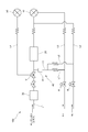
- the schematic diagram which shows the structure of the gas analyzer of this embodiment The figure which shows the operation
- the gas analyzer 100 of this embodiment is an exhaust gas analyzer that measures the concentration of a component contained in a sample gas such as exhaust gas discharged from an internal combustion engine of a vehicle.
- a sample gas such as exhaust gas discharged from an internal combustion engine of a vehicle.
- An exhaust gas analysis system is constructed with a constant volume sampling device (CVS) that samples at a constant flow rate.
- the exhaust gas analysis system may be a dilution sampling system that dilutes the exhaust gas and measures the concentration, or a direct sampling system that measures the concentration as it is without dilution.
- the gas analyzer 100 measures the concentration of a measurement gas component L1 provided in the sample gas line L1 through which the exhaust gas as the sample gas flows and the sample gas line L1 is included in the sample gas
- the analyzer 10 is provided.
- the analyzer 10 measures hydrocarbon (HC), which is an organic compound, as a measurement target component, and has an FID detector using a flame ionization analysis method (FID), which is included in the sample gas here.
- HC hydrocarbon
- FID flame ionization analysis method
- THC total hydrocarbon
- the analyzer 10 is connected to an analysis gas line L2 to which hydrogen gas as an analysis gas is supplied and an auxiliary combustion gas line L3 to which air as an auxiliary combustion gas is supplied.
- Analytical gas and auxiliary combustion gas are mixed at a fixed ratio and introduced into a hydrogen flame, and the hydrocarbon (HC) concentration can be continuously measured based on the ionic current generated by ionizing HC by combustion at this time. It is configured.
- the gas analyzer 100 of the present embodiment is provided on the upstream side of the analyzer 10 in the sample gas line L1, and removes hydrocarbons (components to be removed) other than methane from the sample gas.
- An oxidation catalyst 20 is provided.
- a branch line L4 branched from the upstream side of the oxidation catalyst 20 and joined to the downstream side, and a switching valve V such as a three-way valve for selectively flowing the sample gas to the branch line L4 or the oxidation catalyst 20; Is provided.
- the concentration of total hydrocarbons (THC) can be measured by flowing the sample gas through the branch line L4, and the concentration of methane contained in the sample gas is measured by flowing the sample gas through the oxidation catalyst 20. Based on these differences, the concentration of non-methane hydrocarbon (NMHC) contained in the sample gas can be calculated.
- THC total hydrocarbons
- NMHC non-methane hydrocarbon
- the oxidation catalyst 20 described above is a metal catalyst called a so-called non-methane cutter, and specifically includes manganese dioxide (IV) and copper (II) oxide, and is used within a defined temperature range such as 600K or more. Is done.
- the separation performance of this non-methane cutter is evaluated by, for example, the transmission efficiency of methane and the transmission efficiency of ethane, which is a hydrocarbon other than methane, and the transmission efficiency varies depending on the temperature of the methane cutter. Also changes according to the temperature of the non-methane cutter.
- the separation ability of the non-methane cutter can be increased (for example, the methane transmission efficiency is 85% or more and the ethane transmission efficiency is 2% or less).
- the gas analyzer 100 of the present embodiment further includes a moisture concentration adjusting unit 30 that is provided on the upstream side of the oxidation catalyst 20 in the sample gas line L1 and adjusts the moisture concentration of the sample gas as shown in FIG. It becomes.
- the moisture concentration adjusting unit 30 is configured to change the temperature of the sample gas to keep the moisture concentration constant, and lowers the moisture concentration contained in the sample gas to a preset concentration.
- the moisture concentration adjusting unit 30 here uses a dehumidifier that cools and dehumidifies the sample gas, and this dehumidifier is, for example, a compressor type using a compressor.
- the set concentration can be changed as appropriate according to the specifications.
- the moisture concentration adjusting unit 30 may be one that adjusts the moisture concentration by changing the pressure of the sample gas, or that adjusts the moisture concentration by changing both the temperature and pressure of the sample gas. There may be.
- the gas analyzer 100 of the present embodiment includes a moisture supply unit 40 that supplies moisture between the moisture concentration adjusting unit 30 and the oxidation catalyst 20 in the sample gas line L1.
- the moisture supply unit 40 includes a moisture supply line L5 connected between the moisture concentration adjusting unit 30 and the oxidation catalyst 20 in the sample gas line L1, a hydrogen introduction line L6 that introduces hydrogen into the moisture supply line L5, and moisture.
- An oxygen introduction line L7 that introduces oxygen into the supply line L5 and a platinum catalyst 41 that is provided in the moisture supply line L5 and reacts with hydrogen and oxygen to produce moisture are provided.
- the hydrogen introduction line L6 is a line through which a gas consisting only of hydrogen or a gas containing hydrogen at a predetermined concentration flows, and a part thereof is also used as the above-described analysis gas line L2.
- the oxygen introduction line L7 is a line for introducing a gas consisting only of oxygen or a gas containing oxygen at a predetermined concentration.
- the oxygen introduction line L7 here is a line through which air flows, and a part of the oxygen introduction line L7 is also used as the auxiliary combustion gas line L3 described above.
- Each of the hydrogen introduction line L6 and the oxygen introduction line L7 is provided with a regulator R.
- the amount of moisture generated that is, The amount of water supplied to the sample gas line L1 can be controlled to a predetermined amount.
- the moisture supply unit 40 of the present embodiment supplies 1 to 2 vol% of moisture to the sample gas line L1.
- the analyzer 10 when the analyzer 10 is calibrated, for example, a calibration gas containing methane having a known concentration is introduced into the sample gas line L1. Thereby, the analyzer 10 can be calibrated as needed by comparing the known concentration of methane contained in the calibration gas with the measured concentration of methane obtained using the analyzer 10.
- the calibration gas may be a gas containing ethane or propane having a known concentration.
- the calibration gas used here is a gas that contains less moisture than the exhaust gas that is the sample gas. For this reason, if the moisture concentration adjusting unit 30 is not provided, the amount of moisture supplied to the non-methane cutter differs between calibration and analysis. In this case, the separation ability of the non-methane cutter is different between the calibration and the analysis, and the analysis accuracy is lowered. Therefore, in this embodiment, the calibration gas used during calibration is introduced into the sample gas line L1 so that the calibration gas passes through the moisture concentration adjusting unit 30.
- a calibration gas for calibrating the analyzer 10 is introduced into the sample gas line L1 (S1).
- the switching valve V at this time is in a state where the calibration gas flows to the non-methane cutter.
- the calibration gas flows into the non-methane cutter and hydrocarbons other than methane are removed. Then, the analyzer 10 measures the methane concentration contained in the calibration gas (S2).
- the user compares the measured concentration of methane obtained by the analyzer 10 with the known concentration of methane actually contained in the calibration gas, and calibrates the analyzer 10 as necessary (S3). .
- the exhaust gas as the sample gas is introduced into the sample gas line L1 (S4).
- the switching valve V at this time is in a state where the calibration gas flows through the branch line L4.
- the sample gas is guided to the analyzer 10 without passing through the non-methane cutter, and the concentration of all hydrocarbons contained in the sample gas is measured by the analyzer 10 (S5).
- the switching valve V is switched so that the sample gas flows to the non-methane cutter (S6).
- the analyzer 10 measures the methane concentration contained in the sample gas (S7).
- an arithmetic processing unit (not shown) provided in the analyzer 10 or provided separately from the analyzer 10 is configured to generate non-methane hydrocarbon (NMHC) contained in the sample gas based on the difference between the total hydrocarbon concentration and the methane concentration.
- NMHC non-methane hydrocarbon
- the moisture concentration contained in the sample gas is lowered to a constant concentration by the dehumidifier, and a predetermined amount of moisture is supplied to the sample gas. Even if the moisture concentration in the exhaust gas fluctuates according to the operating state, the moisture supplied to the oxidation catalyst 20 can be kept constant. Thereby, the fluctuation
- the calibration gas is introduced into the sample gas line L1 and passes through the moisture concentration adjusting unit 30 and a predetermined amount of moisture is supplied, oxidation is performed during measurement of the sample gas and during calibration of the analyzer 10.
- the separation ability of the catalyst 20 can be made equal, and the analysis accuracy can be further improved.
- the present invention is not limited to the above embodiment.
- the branch line L4 branched from the upstream side of the non-methane cutter does not join the downstream side of the non-methane cutter, for example, the second analyzer 50 (THC) that analyzes all hydrocarbons. May be connected to the total).
- the analyzer 10 may be a CH 4 meter that measures the concentration of methane. Note that these THC meters and CH 4 meters have FID detectors as in this embodiment. If it is such a structure, the concentration measurement of all the hydrocarbons of S5 in the said embodiment and the concentration measurement of methane in S7 can be performed in parallel.
- An arithmetic processing device may include a moisture partial pressure correction unit. Specifically, the moisture partial pressure correction unit obtains removed moisture amount data indicating the amount of moisture in the sample gas removed by the moisture concentration adjusting unit 30, and the methane concentration and total hydrocarbons according to the moisture amount. A configuration for correcting the density can be mentioned.
- a desiccant type dehumidifier using a desiccant such as a porous mineral may be used.
- the moisture concentration adjusting unit 30 may be configured such that the introduced sample gas passes through, for example, the liquid stored in the tank. More specifically, for example, by bubbling the liquid with the sample gas while keeping the liquid in the tank at a constant temperature, the water contained in the sample gas becomes saturated, and the amount of water in the sample gas is kept constant. be able to. If the moisture in the sample gas can be adjusted to a desired amount with such a configuration, the moisture supply unit 40 in the embodiment can be dispensed with.
- the methane concentration is measured after measuring the total hydrocarbon concentration contained in the sample gas.
- the total hydrocarbon concentration may be measured after measuring the methane concentration.
- the calibration gas that has passed through the concentration adjusting unit 30 remains lower than the set concentration of the concentration adjusting unit 30 and is converted into a non-methane cutter during calibration and during analysis. There will be a difference in the amount of water supplied. Therefore, when the analyzer 10 is calibrated using the calibration gas, the calibration gas may be humidified and then flowed to the moisture concentration adjusting unit 30. As a result, the moisture concentration of the calibration gas that has passed through the moisture concentration adjusting unit 30 is obtained by causing the calibration gas to flow to the moisture concentration adjusting unit 30 after the moisture concentration contained in the calibration gas is equal to or higher than the set concentration of the moisture concentration adjusting unit 30. Can be set to the set concentration, and the difference in the amount of water supplied to the non-methane cutter between calibration and analysis can be made as small as possible.
- the analyzer 10 may be one using infrared absorption such as a CO meter or a CO 2 meter.
- the gas analyzer 100 according to the present invention can be used as a vehicle-mounted device mounted on a vehicle.
- the set temperature of the moisture concentration adjusting unit 30 is increased to suppress power consumption, or the moisture concentration adjusting unit 30 is described above.
- a desiccant dehumidifier may be used.
- the gas analyzer 100 according to the present invention can also be used as a catalyst evaluation device.
- the sample gas can be applied not only to the exhaust gas of the internal combustion engine but also to various gases such as a combustion engine such as a boiler, a gas introduced and removed in a chemical reaction furnace, and the like.
- the gas analyzer By using the gas analyzer according to the present invention, it is possible to accurately measure the sample gas while ensuring the separation performance required for an oxidation catalyst such as a non-methane cutter.
Landscapes
- Chemical & Material Sciences (AREA)
- Life Sciences & Earth Sciences (AREA)
- Health & Medical Sciences (AREA)
- Engineering & Computer Science (AREA)
- Physics & Mathematics (AREA)
- General Physics & Mathematics (AREA)
- Biochemistry (AREA)
- Analytical Chemistry (AREA)
- General Health & Medical Sciences (AREA)
- Immunology (AREA)
- Pathology (AREA)
- Combustion & Propulsion (AREA)
- Molecular Biology (AREA)
- Chemical Kinetics & Catalysis (AREA)
- Food Science & Technology (AREA)
- Medicinal Chemistry (AREA)
- Biomedical Technology (AREA)
- Sampling And Sample Adjustment (AREA)
- Investigating Or Analyzing Non-Biological Materials By The Use Of Chemical Means (AREA)
Abstract
Afin d'assurer la capacité de séparation exigée d'un catalyseur d'oxydation tel qu'un dispositif de coupe sans méthane et afin de permettre à un échantillon de gaz d'être mesuré avec précision, l'invention concerne un dispositif d'analyse de gaz qui est pourvu : d'une ligne d'échantillon gazeux L1 à travers laquelle s'écoule un échantillon gazeux ; d'un analyseur 10 situé dans la ligne d'échantillon gazeux L1 et qui détecte la concentration d'un composant particulier contenu dans l'échantillon gazeux ; d'un catalyseur 20 situé en amont de l'analyseur 10 dans la ligne d'échantillon gazeux L1 et qui réagit avec l'échantillon gazeux ; d'une unité de réglage de la concentration d'humidité 30 située en amont du catalyseur 20 dans la ligne d'échantillon gazeux L1 afin de régler la concentration d'humidité de l'échantillon gazeux.
Priority Applications (4)
| Application Number | Priority Date | Filing Date | Title |
|---|---|---|---|
| EP17878611.7A EP3553491B1 (fr) | 2016-12-08 | 2017-08-14 | Dispositif et procédé d'analyse de gaz |
| CN201780074916.3A CN110036271A (zh) | 2016-12-08 | 2017-08-14 | 气体分析装置和气体分析方法 |
| US16/465,751 US11035756B2 (en) | 2016-12-08 | 2017-08-14 | Gas analyzing device and gas analyzing method |
| JP2018554817A JP7001616B2 (ja) | 2016-12-08 | 2017-08-14 | ガス分析装置及びガス分析方法 |
Applications Claiming Priority (2)
| Application Number | Priority Date | Filing Date | Title |
|---|---|---|---|
| JP2016238143 | 2016-12-08 | ||
| JP2016-238143 | 2016-12-08 |
Publications (1)
| Publication Number | Publication Date |
|---|---|
| WO2018105169A1 true WO2018105169A1 (fr) | 2018-06-14 |
Family
ID=62490927
Family Applications (1)
| Application Number | Title | Priority Date | Filing Date |
|---|---|---|---|
| PCT/JP2017/029279 Ceased WO2018105169A1 (fr) | 2016-12-08 | 2017-08-14 | Dispositif et procédé d'analyse de gaz |
Country Status (5)
| Country | Link |
|---|---|
| US (1) | US11035756B2 (fr) |
| EP (1) | EP3553491B1 (fr) |
| JP (1) | JP7001616B2 (fr) |
| CN (1) | CN110036271A (fr) |
| WO (1) | WO2018105169A1 (fr) |
Cited By (3)
| Publication number | Priority date | Publication date | Assignee | Title |
|---|---|---|---|---|
| EP3623806A1 (fr) * | 2018-08-17 | 2020-03-18 | HORIBA, Ltd. | Appareil d'analyse de gaz et procédé d'analyse de gaz |
| WO2020066308A1 (fr) * | 2018-09-28 | 2020-04-02 | 株式会社堀場製作所 | Dispositif d'analyse de gaz et procédé d'étalonnage pour dispositif d'analyse de gaz |
| JPWO2022075353A1 (fr) * | 2020-10-09 | 2022-04-14 |
Families Citing this family (6)
| Publication number | Priority date | Publication date | Assignee | Title |
|---|---|---|---|---|
| GB201903473D0 (en) * | 2019-03-14 | 2019-05-01 | Sumitomo Chemical Co | Interferent and baseline drift correcting gas sensor system |
| CN111879844B (zh) * | 2020-07-15 | 2022-10-25 | 聚光科技(杭州)股份有限公司 | 气态污染物中多成分的检测方法 |
| US12339220B2 (en) | 2021-02-18 | 2025-06-24 | Aerodyne Research, Inc. | Rapid, sensitive hydrogen detector with flow path difference compensation |
| AU2024391123A1 (en) * | 2023-12-01 | 2026-04-02 | Aerodyne Research, Inc. | Optical detector employing controlled water vapor concentration over catalyst |
| GB2639019A (en) * | 2024-03-07 | 2025-09-10 | Jaguar Land Rover Ltd | Module for supplying gas |
| KR102942413B1 (ko) | 2025-10-16 | 2026-03-23 | (주)리얼텍 | 잔류 가스 분석 방법, 장치 및 시스템 |
Citations (7)
| Publication number | Priority date | Publication date | Assignee | Title |
|---|---|---|---|---|
| JPS63308535A (ja) * | 1987-06-10 | 1988-12-15 | Mazda Motor Corp | エンジン排気系の評価装置 |
| JPH0552755U (ja) * | 1991-12-17 | 1993-07-13 | 株式会社堀場製作所 | メタン分析装置 |
| JPH06123682A (ja) * | 1992-10-13 | 1994-05-06 | Mitsubishi Heavy Ind Ltd | NOx 濃度の計測装置 |
| JPH0835950A (ja) | 1994-07-23 | 1996-02-06 | Horiba Ltd | 炭化水素分析方法とその分析装置およびメタン・ノンメタン成分の分離能向上のための装置 |
| JPH09273991A (ja) * | 1996-04-06 | 1997-10-21 | Horiba Ltd | 赤外線ガス分析計 |
| JP2003315220A (ja) * | 2002-02-19 | 2003-11-06 | Horiba Ltd | 窒素酸化物測定装置 |
| JP2005055246A (ja) * | 2003-08-01 | 2005-03-03 | Horiba Ltd | ガスサンプリング装置 |
Family Cites Families (3)
| Publication number | Priority date | Publication date | Assignee | Title |
|---|---|---|---|---|
| US6878339B2 (en) | 2002-02-19 | 2005-04-12 | Horiba, Ltd. | NOx-concentration measuring apparatus |
| US7435284B2 (en) * | 2005-11-17 | 2008-10-14 | Thermo Electron Corporation | Parallel-plate diffusion gas dehumidifier and methods for use |
| JP5967908B2 (ja) | 2011-11-29 | 2016-08-10 | 三菱日立パワーシステムズ株式会社 | 窒素酸化物計測器 |
-
2017
- 2017-08-14 WO PCT/JP2017/029279 patent/WO2018105169A1/fr not_active Ceased
- 2017-08-14 JP JP2018554817A patent/JP7001616B2/ja active Active
- 2017-08-14 EP EP17878611.7A patent/EP3553491B1/fr active Active
- 2017-08-14 CN CN201780074916.3A patent/CN110036271A/zh active Pending
- 2017-08-14 US US16/465,751 patent/US11035756B2/en active Active
Patent Citations (7)
| Publication number | Priority date | Publication date | Assignee | Title |
|---|---|---|---|---|
| JPS63308535A (ja) * | 1987-06-10 | 1988-12-15 | Mazda Motor Corp | エンジン排気系の評価装置 |
| JPH0552755U (ja) * | 1991-12-17 | 1993-07-13 | 株式会社堀場製作所 | メタン分析装置 |
| JPH06123682A (ja) * | 1992-10-13 | 1994-05-06 | Mitsubishi Heavy Ind Ltd | NOx 濃度の計測装置 |
| JPH0835950A (ja) | 1994-07-23 | 1996-02-06 | Horiba Ltd | 炭化水素分析方法とその分析装置およびメタン・ノンメタン成分の分離能向上のための装置 |
| JPH09273991A (ja) * | 1996-04-06 | 1997-10-21 | Horiba Ltd | 赤外線ガス分析計 |
| JP2003315220A (ja) * | 2002-02-19 | 2003-11-06 | Horiba Ltd | 窒素酸化物測定装置 |
| JP2005055246A (ja) * | 2003-08-01 | 2005-03-03 | Horiba Ltd | ガスサンプリング装置 |
Non-Patent Citations (1)
| Title |
|---|
| See also references of EP3553491A4 |
Cited By (8)
| Publication number | Priority date | Publication date | Assignee | Title |
|---|---|---|---|---|
| EP3623806A1 (fr) * | 2018-08-17 | 2020-03-18 | HORIBA, Ltd. | Appareil d'analyse de gaz et procédé d'analyse de gaz |
| US11327047B2 (en) | 2018-08-17 | 2022-05-10 | Horiba, Ltd. | Gas analysis apparatus and gas analysis method |
| WO2020066308A1 (fr) * | 2018-09-28 | 2020-04-02 | 株式会社堀場製作所 | Dispositif d'analyse de gaz et procédé d'étalonnage pour dispositif d'analyse de gaz |
| JPWO2020066308A1 (ja) * | 2018-09-28 | 2021-09-09 | 株式会社堀場製作所 | ガス分析装置及びガス分析装置の校正方法 |
| JP7293248B2 (ja) | 2018-09-28 | 2023-06-19 | 株式会社堀場製作所 | ガス分析装置及びガス分析装置の校正方法 |
| JPWO2022075353A1 (fr) * | 2020-10-09 | 2022-04-14 | ||
| WO2022075353A1 (fr) * | 2020-10-09 | 2022-04-14 | 株式会社堀場製作所 | Dispositif d'analyse de gaz et procédé d'analyse de gaz |
| JP7638294B2 (ja) | 2020-10-09 | 2025-03-03 | 株式会社堀場製作所 | ガス分析装置及びガス分析方法 |
Also Published As
| Publication number | Publication date |
|---|---|
| US20190391045A1 (en) | 2019-12-26 |
| EP3553491A1 (fr) | 2019-10-16 |
| EP3553491A4 (fr) | 2020-08-19 |
| CN110036271A (zh) | 2019-07-19 |
| JPWO2018105169A1 (ja) | 2019-10-24 |
| US11035756B2 (en) | 2021-06-15 |
| JP7001616B2 (ja) | 2022-01-19 |
| EP3553491B1 (fr) | 2024-06-19 |
Similar Documents
| Publication | Publication Date | Title |
|---|---|---|
| JP7001616B2 (ja) | ガス分析装置及びガス分析方法 | |
| EP3480593B1 (fr) | Procédé et système d'étalonnage pour appareil d'analyse de gaz | |
| US7454950B2 (en) | Vehicle exhaust gas analyzer | |
| JP7267161B2 (ja) | 排ガス分析装置、排ガス分析方法、及び補正式作成方法 | |
| CN108226268B (zh) | 气体分析装置、气体取样装置和气体分析方法 | |
| US20190064035A1 (en) | Exhaust Gas Analysis Device, Exhaust Gas Analysis Method and Storage Medium Recording Programs for Exhaust Gas Analysis Device | |
| JP4413160B2 (ja) | 排気ガス成分分析装置 | |
| WO2022211111A1 (fr) | Système de mesure de la quantité d'hydrogène consommé | |
| US11327047B2 (en) | Gas analysis apparatus and gas analysis method | |
| JP4925489B1 (ja) | ガス分析装置 | |
| JP6093607B2 (ja) | 排ガス分析装置 | |
| JP4804782B2 (ja) | 窒素酸化物分析計及び窒素酸化物分析計に適用されるパラメータ設定方法 | |
| JP2013105299A (ja) | 混合ガス流量制御装置および排ガス浄化触媒評価装置 | |
| US20230375503A1 (en) | Gas analysis device and gas analysis method | |
| JP2006284502A (ja) | ガス分析装置及び水素炎イオン化検出器の制御方法 | |
| CN203587565U (zh) | 一种sf6气相色谱检测系统 | |
| JP2001159587A (ja) | ガス分析装置 | |
| JP4550645B2 (ja) | 車両搭載型排気ガス分析装置 | |
| JP7528237B2 (ja) | ガス分析装置及びガス分析方法 | |
| JP4319471B2 (ja) | 試料ガス濃度計 | |
| JP3789093B2 (ja) | 水素濃度測定装置 | |
| JP2020134278A (ja) | ガス分析方法及びガス分析装置 | |
| JP2014162663A (ja) | 試料ガス中の硫黄化合物の酸化方法及び装置並びに分析装置 | |
| JP2012181126A (ja) | 酸素濃度の分析方法及び装置 |
Legal Events
| Date | Code | Title | Description |
|---|---|---|---|
| 121 | Ep: the epo has been informed by wipo that ep was designated in this application |
Ref document number: 17878611 Country of ref document: EP Kind code of ref document: A1 |
|
| ENP | Entry into the national phase |
Ref document number: 2018554817 Country of ref document: JP Kind code of ref document: A |
|
| NENP | Non-entry into the national phase |
Ref country code: DE |
|
| ENP | Entry into the national phase |
Ref document number: 2017878611 Country of ref document: EP Effective date: 20190708 |