WO2018105175A1 - Procédé de traitement d'informations, système de traitement d'informations et dispositif de traitement d'informations - Google Patents
Procédé de traitement d'informations, système de traitement d'informations et dispositif de traitement d'informations Download PDFInfo
- Publication number
- WO2018105175A1 WO2018105175A1 PCT/JP2017/030288 JP2017030288W WO2018105175A1 WO 2018105175 A1 WO2018105175 A1 WO 2018105175A1 JP 2017030288 W JP2017030288 W JP 2017030288W WO 2018105175 A1 WO2018105175 A1 WO 2018105175A1
- Authority
- WO
- WIPO (PCT)
- Prior art keywords
- information
- machine tool
- information processing
- machine tools
- machine
- Prior art date
- Legal status (The legal status is an assumption and is not a legal conclusion. Google has not performed a legal analysis and makes no representation as to the accuracy of the status listed.)
- Ceased
Links
Images







Classifications
-
- B—PERFORMING OPERATIONS; TRANSPORTING
- B23—MACHINE TOOLS; METAL-WORKING NOT OTHERWISE PROVIDED FOR
- B23Q—DETAILS, COMPONENTS, OR ACCESSORIES FOR MACHINE TOOLS, e.g. ARRANGEMENTS FOR COPYING OR CONTROLLING; MACHINE TOOLS IN GENERAL CHARACTERISED BY THE CONSTRUCTION OF PARTICULAR DETAILS OR COMPONENTS; COMBINATIONS OR ASSOCIATIONS OF METAL-WORKING MACHINES, NOT DIRECTED TO A PARTICULAR RESULT
- B23Q17/00—Arrangements for observing, indicating or measuring on machine tools
- B23Q17/09—Arrangements for observing, indicating or measuring on machine tools for indicating or measuring cutting pressure or for determining cutting-tool condition, e.g. cutting ability, load on tool
- B23Q17/0995—Tool life management
-
- G—PHYSICS
- G05—CONTROLLING; REGULATING
- G05B—CONTROL OR REGULATING SYSTEMS IN GENERAL; FUNCTIONAL ELEMENTS OF SUCH SYSTEMS; MONITORING OR TESTING ARRANGEMENTS FOR SUCH SYSTEMS OR ELEMENTS
- G05B23/00—Testing or monitoring of control systems or parts thereof
- G05B23/02—Electric testing or monitoring
- G05B23/0205—Electric testing or monitoring by means of a monitoring system capable of detecting and responding to faults
- G05B23/0259—Electric testing or monitoring by means of a monitoring system capable of detecting and responding to faults characterized by the response to fault detection
- G05B23/0283—Predictive maintenance, e.g. involving the monitoring of a system and, based on the monitoring results, taking decisions on the maintenance schedule of the monitored system; Estimating remaining useful life [RUL]
-
- B—PERFORMING OPERATIONS; TRANSPORTING
- B23—MACHINE TOOLS; METAL-WORKING NOT OTHERWISE PROVIDED FOR
- B23Q—DETAILS, COMPONENTS, OR ACCESSORIES FOR MACHINE TOOLS, e.g. ARRANGEMENTS FOR COPYING OR CONTROLLING; MACHINE TOOLS IN GENERAL CHARACTERISED BY THE CONSTRUCTION OF PARTICULAR DETAILS OR COMPONENTS; COMBINATIONS OR ASSOCIATIONS OF METAL-WORKING MACHINES, NOT DIRECTED TO A PARTICULAR RESULT
- B23Q17/00—Arrangements for observing, indicating or measuring on machine tools
- B23Q17/09—Arrangements for observing, indicating or measuring on machine tools for indicating or measuring cutting pressure or for determining cutting-tool condition, e.g. cutting ability, load on tool
-
- G—PHYSICS
- G05—CONTROLLING; REGULATING
- G05B—CONTROL OR REGULATING SYSTEMS IN GENERAL; FUNCTIONAL ELEMENTS OF SUCH SYSTEMS; MONITORING OR TESTING ARRANGEMENTS FOR SUCH SYSTEMS OR ELEMENTS
- G05B13/00—Adaptive control systems, i.e. systems automatically adjusting themselves to have a performance which is optimum according to some preassigned criterion
- G05B13/02—Adaptive control systems, i.e. systems automatically adjusting themselves to have a performance which is optimum according to some preassigned criterion electric
- G05B13/0205—Adaptive control systems, i.e. systems automatically adjusting themselves to have a performance which is optimum according to some preassigned criterion electric not using a model or a simulator of the controlled system
- G05B13/024—Adaptive control systems, i.e. systems automatically adjusting themselves to have a performance which is optimum according to some preassigned criterion electric not using a model or a simulator of the controlled system in which a parameter or coefficient is automatically adjusted to optimise the performance
-
- G—PHYSICS
- G05—CONTROLLING; REGULATING
- G05B—CONTROL OR REGULATING SYSTEMS IN GENERAL; FUNCTIONAL ELEMENTS OF SUCH SYSTEMS; MONITORING OR TESTING ARRANGEMENTS FOR SUCH SYSTEMS OR ELEMENTS
- G05B13/00—Adaptive control systems, i.e. systems automatically adjusting themselves to have a performance which is optimum according to some preassigned criterion
- G05B13/02—Adaptive control systems, i.e. systems automatically adjusting themselves to have a performance which is optimum according to some preassigned criterion electric
- G05B13/0265—Adaptive control systems, i.e. systems automatically adjusting themselves to have a performance which is optimum according to some preassigned criterion electric the criterion being a learning criterion
-
- G—PHYSICS
- G05—CONTROLLING; REGULATING
- G05B—CONTROL OR REGULATING SYSTEMS IN GENERAL; FUNCTIONAL ELEMENTS OF SUCH SYSTEMS; MONITORING OR TESTING ARRANGEMENTS FOR SUCH SYSTEMS OR ELEMENTS
- G05B19/00—Program-control systems
- G05B19/02—Program-control systems electric
- G05B19/18—Numerical control [NC], i.e. automatically operating machines, in particular machine tools, e.g. in a manufacturing environment, so as to execute positioning, movement or co-ordinated operations by means of program data in numerical form
-
- G—PHYSICS
- G05—CONTROLLING; REGULATING
- G05B—CONTROL OR REGULATING SYSTEMS IN GENERAL; FUNCTIONAL ELEMENTS OF SUCH SYSTEMS; MONITORING OR TESTING ARRANGEMENTS FOR SUCH SYSTEMS OR ELEMENTS
- G05B19/00—Program-control systems
- G05B19/02—Program-control systems electric
- G05B19/18—Numerical control [NC], i.e. automatically operating machines, in particular machine tools, e.g. in a manufacturing environment, so as to execute positioning, movement or co-ordinated operations by means of program data in numerical form
- G05B19/406—Numerical control [NC], i.e. automatically operating machines, in particular machine tools, e.g. in a manufacturing environment, so as to execute positioning, movement or co-ordinated operations by means of program data in numerical form characterised by monitoring or safety
- G05B19/4065—Monitoring tool breakage, life or condition
-
- G—PHYSICS
- G05—CONTROLLING; REGULATING
- G05B—CONTROL OR REGULATING SYSTEMS IN GENERAL; FUNCTIONAL ELEMENTS OF SUCH SYSTEMS; MONITORING OR TESTING ARRANGEMENTS FOR SUCH SYSTEMS OR ELEMENTS
- G05B19/00—Program-control systems
- G05B19/02—Program-control systems electric
- G05B19/418—Total factory control, i.e. centrally controlling a plurality of machines, e.g. direct or distributed numerical control [DNC], flexible manufacturing systems [FMS], integrated manufacturing systems [IMS] or computer integrated manufacturing [CIM]
- G05B19/4184—Total factory control, i.e. centrally controlling a plurality of machines, e.g. direct or distributed numerical control [DNC], flexible manufacturing systems [FMS], integrated manufacturing systems [IMS] or computer integrated manufacturing [CIM] characterised by fault tolerance, reliability of production system
-
- G—PHYSICS
- G05—CONTROLLING; REGULATING
- G05B—CONTROL OR REGULATING SYSTEMS IN GENERAL; FUNCTIONAL ELEMENTS OF SUCH SYSTEMS; MONITORING OR TESTING ARRANGEMENTS FOR SUCH SYSTEMS OR ELEMENTS
- G05B23/00—Testing or monitoring of control systems or parts thereof
- G05B23/02—Electric testing or monitoring
- G05B23/0205—Electric testing or monitoring by means of a monitoring system capable of detecting and responding to faults
- G05B23/0218—Electric testing or monitoring by means of a monitoring system capable of detecting and responding to faults characterised by the fault detection method dealing with either existing or incipient faults
- G05B23/0224—Process history based detection method, e.g. whereby history implies the availability of large amounts of data
- G05B23/0227—Qualitative history assessment, whereby the type of data acted upon, e.g. waveforms, images or patterns, is not relevant, e.g. rule based assessment; if-then decisions
- G05B23/0229—Qualitative history assessment, whereby the type of data acted upon, e.g. waveforms, images or patterns, is not relevant, e.g. rule based assessment; if-then decisions knowledge based, e.g. expert systems; genetic algorithms
-
- G—PHYSICS
- G05—CONTROLLING; REGULATING
- G05B—CONTROL OR REGULATING SYSTEMS IN GENERAL; FUNCTIONAL ELEMENTS OF SUCH SYSTEMS; MONITORING OR TESTING ARRANGEMENTS FOR SUCH SYSTEMS OR ELEMENTS
- G05B23/00—Testing or monitoring of control systems or parts thereof
- G05B23/02—Electric testing or monitoring
- G05B23/0205—Electric testing or monitoring by means of a monitoring system capable of detecting and responding to faults
- G05B23/0218—Electric testing or monitoring by means of a monitoring system capable of detecting and responding to faults characterised by the fault detection method dealing with either existing or incipient faults
- G05B23/0224—Process history based detection method, e.g. whereby history implies the availability of large amounts of data
- G05B23/024—Quantitative history assessment, e.g. mathematical relationships between available data; Functions therefor; Principal component analysis [PCA]; Partial least square [PLS]; Statistical classifiers, e.g. Bayesian networks, linear regression or correlation analysis; Neural networks
-
- G—PHYSICS
- G05—CONTROLLING; REGULATING
- G05B—CONTROL OR REGULATING SYSTEMS IN GENERAL; FUNCTIONAL ELEMENTS OF SUCH SYSTEMS; MONITORING OR TESTING ARRANGEMENTS FOR SUCH SYSTEMS OR ELEMENTS
- G05B23/00—Testing or monitoring of control systems or parts thereof
- G05B23/02—Electric testing or monitoring
- G05B23/0205—Electric testing or monitoring by means of a monitoring system capable of detecting and responding to faults
- G05B23/0259—Electric testing or monitoring by means of a monitoring system capable of detecting and responding to faults characterized by the response to fault detection
- G05B23/0275—Fault isolation and identification, e.g. classify fault; estimate cause or root of failure
-
- G—PHYSICS
- G05—CONTROLLING; REGULATING
- G05B—CONTROL OR REGULATING SYSTEMS IN GENERAL; FUNCTIONAL ELEMENTS OF SUCH SYSTEMS; MONITORING OR TESTING ARRANGEMENTS FOR SUCH SYSTEMS OR ELEMENTS
- G05B23/00—Testing or monitoring of control systems or parts thereof
- G05B23/02—Electric testing or monitoring
- G05B23/0205—Electric testing or monitoring by means of a monitoring system capable of detecting and responding to faults
- G05B23/0259—Electric testing or monitoring by means of a monitoring system capable of detecting and responding to faults characterized by the response to fault detection
- G05B23/0297—Reconfiguration of monitoring system, e.g. use of virtual sensors; change monitoring method as a response to monitoring results
-
- B—PERFORMING OPERATIONS; TRANSPORTING
- B23—MACHINE TOOLS; METAL-WORKING NOT OTHERWISE PROVIDED FOR
- B23Q—DETAILS, COMPONENTS, OR ACCESSORIES FOR MACHINE TOOLS, e.g. ARRANGEMENTS FOR COPYING OR CONTROLLING; MACHINE TOOLS IN GENERAL CHARACTERISED BY THE CONSTRUCTION OF PARTICULAR DETAILS OR COMPONENTS; COMBINATIONS OR ASSOCIATIONS OF METAL-WORKING MACHINES, NOT DIRECTED TO A PARTICULAR RESULT
- B23Q17/00—Arrangements for observing, indicating or measuring on machine tools
- B23Q17/09—Arrangements for observing, indicating or measuring on machine tools for indicating or measuring cutting pressure or for determining cutting-tool condition, e.g. cutting ability, load on tool
- B23Q17/0952—Arrangements for observing, indicating or measuring on machine tools for indicating or measuring cutting pressure or for determining cutting-tool condition, e.g. cutting ability, load on tool during machining
-
- B—PERFORMING OPERATIONS; TRANSPORTING
- B23—MACHINE TOOLS; METAL-WORKING NOT OTHERWISE PROVIDED FOR
- B23Q—DETAILS, COMPONENTS, OR ACCESSORIES FOR MACHINE TOOLS, e.g. ARRANGEMENTS FOR COPYING OR CONTROLLING; MACHINE TOOLS IN GENERAL CHARACTERISED BY THE CONSTRUCTION OF PARTICULAR DETAILS OR COMPONENTS; COMBINATIONS OR ASSOCIATIONS OF METAL-WORKING MACHINES, NOT DIRECTED TO A PARTICULAR RESULT
- B23Q2717/00—Arrangements for indicating or measuring
- B23Q2717/003—Arrangements for indicating or measuring in lathes
-
- G—PHYSICS
- G05—CONTROLLING; REGULATING
- G05B—CONTROL OR REGULATING SYSTEMS IN GENERAL; FUNCTIONAL ELEMENTS OF SUCH SYSTEMS; MONITORING OR TESTING ARRANGEMENTS FOR SUCH SYSTEMS OR ELEMENTS
- G05B2219/00—Program-control systems
- G05B2219/30—Nc systems
- G05B2219/32—Operator till task planning
- G05B2219/32226—Computer assisted repair, maintenance of system components
-
- Y—GENERAL TAGGING OF NEW TECHNOLOGICAL DEVELOPMENTS; GENERAL TAGGING OF CROSS-SECTIONAL TECHNOLOGIES SPANNING OVER SEVERAL SECTIONS OF THE IPC; TECHNICAL SUBJECTS COVERED BY FORMER USPC CROSS-REFERENCE ART COLLECTIONS [XRACs] AND DIGESTS
- Y02—TECHNOLOGIES OR APPLICATIONS FOR MITIGATION OR ADAPTATION AGAINST CLIMATE CHANGE
- Y02P—CLIMATE CHANGE MITIGATION TECHNOLOGIES IN THE PRODUCTION OR PROCESSING OF GOODS
- Y02P90/00—Enabling technologies with a potential contribution to greenhouse gas [GHG] emissions mitigation
- Y02P90/02—Total factory control, e.g. smart factories, flexible manufacturing systems [FMS] or integrated manufacturing systems [IMS]
Definitions
- This disclosure relates to a technique for collecting various information from a plurality of machine tools.
- Patent Document 1 discloses a preventive maintenance management system capable of predicting a failure of a machine tool.
- Patent Document 2 connects a plurality of NC (Numerical Control) machine tools to a central management device via a network, and connects each NC machine tool to the central management device.
- NC machining support system capable of mutually communicating various types of information is disclosed.
- the central management apparatus collects machining know-how and the like by machine tools from each NC machine tool, for example.
- Patent Document 3 discloses a tool management system capable of creating tool information in a machine tool.
- the tool management system accumulates various cutting tool information, NC command information, tool correction information, and actual cutting data associated with spindle load information and feeds them back during machining by the machine tool.
- Patent Document 4 discloses an industrial machine maintenance system that allows a user to perform efficient maintenance work while providing maintenance information from the manufacturer. .
- the maintenance system is connected to the user-side LAN and the manufacturer-side LAN as necessary via a communication line, and connected to the user-side LAN to monitor predetermined items of industrial machinery.
- Monitoring means for transmitting information to the manufacturer side LAN via the information transmission means, and information transmitting and receiving means for receiving information from the manufacturer side LAN, and a monitor connected to the manufacturer side LAN for receiving
- Monitoring means for automatically diagnosing a failure based on the information and monitoring the industrial machine, and maintenance information transmitting means for automatically transmitting maintenance information to the user side when maintenance is required based on the diagnosis result.
- Patent Document 1 does not disclose the type of information to be collected and the method of using the information.
- Patent Documents 2 and 3 only disclose collecting information based on actual processing data, and do not disclose a method for collecting other information and a method for using the other information.
- Patent Document 4 only discloses collecting monitoring information related to a predetermined item of an industrial machine, and does not disclose a method for collecting other information and a method for using the other information.
- the present disclosure has been made to solve the above-described problems, and an object in one aspect is to provide an information processing method capable of effectively utilizing various information collected from a machine tool. It is to be. An object in another aspect is to provide an information processing system capable of effectively utilizing various information collected from a machine tool. An object of the present invention is to provide an information processing apparatus capable of effectively utilizing various information collected from machine tools.
- the information processing method includes a step of communicating with a plurality of machine tools.
- Each of the plurality of machine tools includes a sensor for detecting information on the machine tool as detection information.
- the step of communicating includes a step of receiving, as collected data, part information relating to parts of the machine tool and detection information by the sensor from each of the plurality of machine tools.
- the information processing method further includes: storing the collected data received from each of the plurality of machine tools in a storage unit; and a plurality of the collected data stored in the storage unit based on the plurality of collected data. Learning a correlation between the component information and the information detected by the sensor in the machine tool.
- the information processing method includes a step of communicating with a plurality of machine tools.
- the step of communicating comprises receiving from each of the plurality of machine tools, the contents of an alarm generated in the machine tool and a countermeasure performed on the machine tool when the alarm is generated, as collected data.
- the information processing method further includes the step of storing the collected data received from each of the plurality of machine tools in a storage unit, and the alarm based on the plurality of collected data stored in the storage unit. Learning a correlation between the alarm and a coping method for the alarm for each type.
- the information processing method includes a step of communicating with a plurality of machine tools.
- Each of the plurality of machine tools includes a sensor for detecting information related to the machine tool as detection information, and a recommendation for recommending candidate control parameter recommended conditions for reducing vibration of the spindle of the machine tool.
- the communicating step is performed by setting information detected by the sensor, a recommended condition selected from the candidates, and a control parameter based on the recommended condition in the machine tool from each of the plurality of machine tools. Receiving the result indicating whether the vibration is reduced or not as collected data.
- the information processing method further includes: storing the collected data received from each of the plurality of machine tools in a storage unit; and a plurality of the collected data stored in the storage unit, Learning a correlation between the detection information by the sensor, the recommended condition selected from the candidates, and the result.
- the information processing method includes a step of communicating with a plurality of machine tools.
- Each of the plurality of machine tools includes a sensor for detecting information related to the machine tool as detection information, and an interface for connecting to a correction device for correcting a control parameter of the machine tool.
- the step of communicating includes the step of receiving detection information by the sensor and correction information of the control parameter by the correction device as collected data from each of the plurality of machine tools.
- the information processing method further includes: storing the collected data received from each of the plurality of machine tools in a storage unit; and a plurality of the collected data stored in the storage unit, Learning a correlation between the detection information by the sensor and the correction information by the correction device.
- the information processing method includes a step of communicating with a plurality of machine tools.
- Each of the plurality of machine tools includes a plurality of sensors for detecting different information regarding the machine tool.
- the step of communicating includes a step of receiving detection information from each of the plurality of sensors in the machine tool as collected data from each of the plurality of machine tools.
- the information processing method further includes: storing the collected data received from each of the plurality of machine tools in a storage unit; and the plurality of the collected data stored in the storage unit based on the plurality of the collected data.
- a step of learning a normal range of detection information for each type of sensor, and when a diagnosis execution instruction is received from any one of the plurality of machine tools and other machine tools, the above in the machine tool Receiving detection information from a plurality of sensors from the machine tool, referring to a learning result in the learning step, diagnosing whether each of the received detection information is within a corresponding normal range; Transmitting the diagnosis result in the diagnosing step to the machine tool that is the transmission source of the execution instruction.
- the information processing system includes an information processing device and a plurality of machine tools capable of communicating with the information processing device.
- Each of the plurality of machine tools includes a sensor for detecting information on the machine tool as detection information.
- the information processing apparatus includes a communication unit for receiving, as collected data, part information related to a part of the machine tool and detection information by the sensor from each of the plurality of machine tools, and each of the plurality of machine tools.
- a storage unit for storing the collected data received from the machine, and based on a plurality of the collected data stored in the storage unit, part information of the machine tool and detection information by a sensor in the machine tool And a learning unit for learning the correlation between them.
- the information processing apparatus includes a communication unit for communicating with a plurality of machine tools.
- Each of the plurality of machine tools includes a sensor for detecting information on the machine tool as detection information.
- the communication unit receives, as collected data, part information related to parts of the machine tool and detection information by the sensor from each of the plurality of machine tools.
- the information processing apparatus further includes a storage unit for storing the collected data received from each of the plurality of machine tools, and a plurality of the collected data stored in the storage unit.
- a learning unit for learning a correlation between the component information and the detection information by the sensor in the machine tool.
- FIG. 1 is a diagram illustrating an example of a system configuration of the information processing system 1.
- the information processing system 1 includes an information processing apparatus 100 and a plurality of machine tools 200A to 200D.
- Machine tools 200A to 200D are arranged in a factory, for example.
- the machine tools 200A to 200D may be the same type of machine tool or different types of machine tools.
- at least one of the machine tools 200A to 200D is also referred to as a machine tool 200.
- a lathe processes a workpiece by applying a tool to the workpiece while rotating the workpiece on a spindle.
- the machining center processes a workpiece by applying the tool to the workpiece while rotating the tool around the spindle.
- the information processing apparatus 100 is a server installed at a location different from the factory where the machine tools 200A to 200D are installed.
- the information processing apparatus 100 collects various information regarding the machine tool from the machine tools 200A to 200D and converts the information into a database.
- the information processing apparatus 100 collects the spindle acceleration detected by the acceleration sensor, the temperature in the machine tool detected by the temperature sensor, information on the hydraulic unit in the machine tool, the monitoring result of the oil cooler, and the like.
- the information collection function may be a physical server, and may be provided in a platform on the cloud, for example.
- the information processing apparatus 100 and the machine tool 200 are connected to each other via a network NW.
- the machine tool 200 is connected to the network NW in an arbitrary manner.
- machine tools 200 ⁇ / b> A and 200 ⁇ / b> B are connected to a network NW via a router 401.
- the machine tool 200C is connected to a network NW via an IO (Input Output) unit and a router 401.
- Machine tool 200D is directly connected to network NW.
- the information processing system 1 may include PCs (Personal Computers) 300A and 300B.
- the PC 300A is indirectly connected to the information processing apparatus 100 via the router 401 via the network.
- the PC 300B is directly connected to the information processing apparatus 100 via a network.
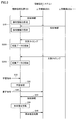
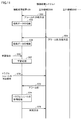
- FIG. 2 is a sequence diagram showing a data flow between the information processing apparatus 100 and the machine tools 200A and 200B.
- Each machine tool 200 includes a sensor for detecting information about itself.
- the information processing apparatus 100 collects part information regarding maintenance parts of the machine tool 200 and detection information by sensors in the machine tool 200 from each of the machine tools 200. Thereafter, the information processing apparatus 100 performs machine learning (data mining) on the correlation between the component information of the machine tool 200 and information detected by the sensor in the machine tool 200 based on information collected from each of the machine tools 200. ) The information processing apparatus 100 refers to the correlation obtained as a learning result, predicts the service life of the maintenance part, and determines whether or not the maintenance part has failed.
- step S10 the information processing apparatus 100 periodically receives detection information from the sensor in the machine tool 200A from the machine tool 200A. A detection time is given to the received detection information, and the information processing apparatus 100 receives the detection information as a detection history. Similarly, the information processing apparatus 100 periodically receives detection information from the sensor in the machine tool 200B from the machine tool 200B. A detection time is given to the received detection information, and the information processing apparatus 100 receives the detection information as a detection history. Detection histories received from the machine tools 200A and 200B are stored in a database 124 described later.
- step S20A Suppose that the maintenance parts of the machine tool 200A are replaced in step S20A.
- the maintenance parts include consumables such as a spindle.
- machine tool 200A Based on the replacement of the maintenance part, machine tool 200A transmits a part ID (Identification) for identifying the maintenance part to be replaced and the replacement timing of the maintenance part to information processing apparatus 100 as part information.
- the information processing apparatus 100 associates the component information received from the machine tool 200A with the detection information of the machine tool 200A received in step S10 until the maintenance component replacement timing, and these pieces of information are shown in FIG. Store in the database 124.
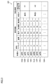
- FIG. 3 is a diagram showing an example of the data structure of the database 124.
- the machine tool device ID, the detection history received in step S10 that is, the detection information and its detection timing
- the article information received in step S20A are associated with each other.
- the detection information to be collected is detected by, for example, the temperature in the machine tool 200A detected by the temperature sensor, the power consumption in the machine tool 200A, the acceleration of the main axis of the machine tool 200A detected by the acceleration sensor, and the current sensor. It includes the value of the current flowing through the maintenance parts in the machine tool 200A.
- the collection target article information includes, for example, a part ID for identifying a maintenance part to be replaced and a replacement timing of the maintenance part.
- step S20B it is assumed that the maintenance parts of the machine tool 200B are replaced in step S20B.
- the machine tool 200B transmits the part ID for identifying the maintenance part to be replaced and the replacement timing of the maintenance part to the information processing apparatus 100 as part information.
- the information processing apparatus 100 associates the component information received from the machine tool 200B with the detection information of the machine tool 200B received in step S10 until the maintenance component replacement timing, and these pieces of information are shown in FIG. Store in the database 124.
- the information processing apparatus 100 receives, as collected data, article information related to a maintenance part to be replaced and information detected by a sensor until the replacement timing of the maintenance part from each of the machine tools 200.
- the information processing apparatus 100 stores the collected data received from each of the machine tools 200 in the database 124.
- the collected data 125A to 125H is accumulated in the database 124.
- step S30 it is assumed that the information processing apparatus 100 receives a learning instruction.
- the learning instruction may be issued based on a user operation on the information processing apparatus 100, or may be issued based on the arrival of a preset learning timing.
- step S32 the information processing apparatus 100 executes a learning process for machine learning of the correlation between the collected data accumulated in the database 124.
- the information processing apparatus 100 performs machine learning on the correlation between the replacement timing of the maintenance parts of the machine tool 200 and the detection information by the sensor in the machine tool 200 based on the database 124. To do.
- the information processing apparatus 100 calculates the time from the detection timing of detection information to the replacement timing of maintenance parts (hereinafter also referred to as “lifetime”) for each of the collected data 125A to 125H. After that, the information processing apparatus 100 performs machine learning on the correlation between each detection information indicated in the database 124 and the lifetime calculated for each detection information for each type of maintenance component. For the machine learning of the correlation, for example, various learning methods such as a neural network and a support vector machine can be adopted.
- FIG. 4 is a diagram illustrating an example of the correlation 126 obtained as a learning result.
- a correlation 126 obtained as a learning result for the maintenance part “1” in the machine tool 200 is shown.
- the horizontal axis of the correlation 126 indicates detection information by a sensor in the machine tool 200.
- the detection information is represented by one dimension for convenience of explanation, but the detection information may be represented by the number of dimensions corresponding to the type of detection information.
- the vertical axis of the correlation 126 indicates the lifetime of the maintenance part “1”.
- step S40 it is assumed that the machine tool 200A receives an instruction from the user for estimating the service life of the maintenance part “1”. Based on this, the machine tool 200A outputs a detection instruction to an internal sensor, and newly acquires detection information from the sensor.
- step S42 the machine tool 200A transmits the newly acquired detection information to the information processing apparatus 100.
- step S44 the information processing apparatus 100 refers to the correlation 126 learned in step S32 based on the newly received detection information from the sensor of the machine tool 200A, and sets the newly received detection information.
- the corresponding life time is specified as the life estimation result of the maintenance part “1”.
- the information processing apparatus 100 estimates the lifetime “ ⁇ T” corresponding to the detection information “m1” as the lifetime of the maintenance component “1”.
- the estimated lifetime is output by an arbitrary method.
- the estimated lifetime may be output as a message on the screen or may be output as audio. For example, a message such as “The life will be reached in about 10 hours” is displayed.
- the service person or the user can recognize the lifetime of the maintenance parts.
- the information processing apparatus 100 receives the detection information “m2” from the machine tool 200A, the information processing apparatus 100 estimates the lifetime “0” corresponding to the detection information “m2” as the lifetime of the maintenance component “1”. . That is, in this case, it is determined that the life of the maintenance component “1” has expired.
- step S46 the information processing apparatus 100 transmits the life estimation result in step S44 to the machine tool 200A.
- the machine tool 200A outputs the life estimation result received from the information processing apparatus 100.
- the lifetime estimation result is output by an arbitrary method.
- the life estimation result may be output on a screen, may be output as a voice, a spare part may be automatically ordered from a manufacturer, or a maintenance request may be made.
- the information processing apparatus 100 collects, from each of the machine tools 200, part information including the failure timing of the maintenance parts of the machine tool 200 and detection information up to the failure timing of the maintenance parts.
- the information processing apparatus 100 performs machine learning on the correlation between the failure timing of the maintenance parts of the machine tool and the detection information by the sensor in the machine tool based on the collected data.
- the information processing apparatus 100 refers to the correlation obtained as a learning result and corresponds to the newly received detection information. Identify timing.
- the information processing apparatus 100 determines the replacement timing of the maintenance part based on the specified failure timing.
- an impurity (contamination) in the coolant of the machine tool 200 may be detected.
- the information processing apparatus 100 collects component information including the purity of coolant and detection information (for example, temperature, coolant hydraulic pressure, etc.) from each of the machine tools 200.
- the information processing apparatus 100 performs machine learning on the correlation between the purity of the coolant and the detection information by the sensor based on the collected data.
- the information processing apparatus 100 refers to the correlation obtained as the learning result, and corresponds to the newly received detection information. Is detected.
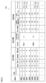
- FIG. 5 is a diagram illustrating an example of the database 124A according to the modification.
- the database 124 shown in FIG. 3 information detected by sensors in the machine tool 200 and parts information related to maintenance parts are collected.
- operation information indicating the operation status of the machine tool 200 is further collected.
- the information processing apparatus 100 collects information detected by the machine tool 200, part information of the machine tool 200, and operation information of the machine tool 200 from each of the machine tools 200.
- the operation information include a travel distance, an operation time of the spindle, a power supply state (ON or OFF), an alarm that has occurred, and the like.
- the information processing apparatus 100 refers to the database 124A during the learning process, and maintains a correlation between detection information by the machine tool 200, parts information of the machine tool 200, and operation information of the machine tool 200 as maintenance parts. Machine learning for each type.
- the failure information of the automatic door cylinder of the machine tool 200 may be collected as the operation information.
- the information processing apparatus 100 can estimate an alarm before the door cylinder breaks down based on the replacement information of the automatic door cylinder, the operation information, and the model information.
- FIG. 6 is a diagram illustrating an example of a functional configuration of the information processing apparatus 100.
- the information processing apparatus 100 includes a control device 101 and a storage device 120 (storage unit) as a hardware configuration.
- the control device 101 includes a communication unit 152, a learning unit 154, a life estimation unit 156, and a failure determination unit 158 as functional configurations.
- the communication unit 152 receives, as collected data, part information related to maintenance parts of the machine tool 200 and information detected by sensors in the machine tool 200 from each of the machine tools 200.
- the collected data received is sequentially accumulated in the database 124 (see FIG. 3) stored in the storage device 120.
- the learning unit 154 performs machine learning on the correlation 126 (see FIG. 4) between the component information of the machine tool 200 and the detection information by the sensor in the machine tool 200 based on the collected data accumulated in the database 124. To do.
- the database 124 collects the replacement timing of maintenance parts of the machine tool 200 and detection information by sensors in the machine tool 200.
- the learning unit 154 refers to the database 124 to machine-learn the correlation between the replacement timing of the maintenance parts of the machine tool 200 and the detection information by the sensors in the machine tool 200.
- the failure timing of the maintenance parts of the machine tool 200 and the detection information by the sensors in the machine tool 200 are collected in the database 124.
- the learning unit 154 refers to the database 124 to machine-learn the correlation between the failure timing of the maintenance parts of the machine tool 200 and the detection information by the sensors in the machine tool 200.
- the life estimation unit 156 refers to the correlation 126 and identifies the replacement timing corresponding to the received detection information for each maintenance component of the machine tool 200. The life estimation unit 156 estimates the life of each maintenance component based on the identified replacement timing.
- the failure determination unit 158 refers to the correlation 126 and specifies the replacement timing corresponding to the received detection information for each maintenance component of the machine tool 200.
- the failure determination unit 158 determines a failure of each maintenance part based on the identified replacement timing.
- FIG. 7 is a flowchart showing learning processing by the information processing apparatus 100.
- FIG. 8 is a flowchart showing a service life estimation process of information processing apparatus 100. 7 and 8 are realized by the control device 101 of the information processing device 100 executing a program. In other aspects, some or all of the processing may be performed by circuit elements or other hardware.
- control device 101 executes the learning process shown in FIG. 7 first, and then executes the life estimation process shown in FIG. Below, the learning process shown in FIG. 7 and the life estimation process shown in FIG. 8 will be described in order.
- step S ⁇ b> 110 control device 101 determines whether or not detection information from the sensor of machine tool 200 has been received from machine tool 200.
- control device 101 determines that the detection information from the sensor of machine tool 200 has been received from machine tool 200 (YES in step S110)
- control device 101 switches control to step S112. If not (NO in step S110), control device 101 switches control to step S120.
- step S112 the control device 101 writes the detection information received from the machine tool 200 in step S110 in the above-described database 124 (see FIG. 3) as the above-described communication unit 152 (see FIG. 6).
- detection information to be collected include temperature in the machine tool 200 detected by the temperature sensor, power consumption in the machine tool 200A, acceleration of the spindle of the machine tool 200A detected by the acceleration sensor, and current sensor. For example, the value of the current flowing through the maintenance part in the machine tool 200A is mentioned.
- step S120 the control device 101 determines whether or not the component information related to the maintenance component has been received from the machine tool 200.
- control device 101 determines that the component information relating to the maintenance component has been received from machine tool 200 (YES in step S120)
- control is switched to step S122. If not (NO in step S120), control device 101 switches control to step S130.
- step S122 the control device 101 writes the component information received from the machine tool 200 in step S110 as the above-described communication unit 152 in the above-described database 124 (see FIG. 3).
- component information to be collected include maintenance component replacement timing, and a component ID for identifying the maintenance component.
- step S130 the control device 101 determines whether or not an instruction for executing the learning process has been received.
- the instruction may be issued based on a user operation on the information processing apparatus 100 or the machine tool 200, or may be issued based on the arrival of a preset learning timing.
- control device 101 determines that an instruction to execute the learning process has been received from the user (YES in step S130)
- control device 101 switches control to step S132. If not (NO in step S130), control device 101 returns control to step S110.
- step S132 the control device 101 performs machine learning on the correlation between the detection information and the component information accumulated in the database 124 as the learning unit 154 (see FIG. 6). As an example of the result, the above-described correlation 126 is obtained.
- step S150 the control apparatus 101 determines whether an instruction for executing the life estimation process has been received.
- the instruction may be issued based on a user operation on the information processing apparatus 100 or the machine tool 200, or may be issued based on the arrival of a preset execution timing.
- control device 101 determines that an instruction to execute the life estimation process has been received (YES in step S150)
- control device 101 switches control to step S152.
- step S150 NO the control apparatus 101 performs the process of step S150 again.
- step S152 the control device 101 transmits a detection command to the machine tool 200 that is a life estimation target.
- the machine tool 200 acquires detection information by a sensor in the machine tool 200 based on the reception of the detection command from the information processing apparatus 100.
- the machine tool 200 transmits the acquired detection information to the information processing apparatus 100.
- step S154 the control apparatus 101 corresponds to the detection information received in step S152 based on the correlation obtained in the learning process shown in FIG. 7 as the above-described life estimation unit 156 (see FIG. 6). Identify the replacement timing of maintenance parts. The control device 101 estimates the service life of the maintenance part based on the identified replacement timing. Since the life estimation process is as described with reference to FIG. 4, the description thereof will not be repeated.
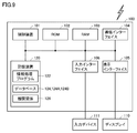
- FIG. 9 is a block diagram illustrating a main hardware configuration of the information processing apparatus 100.
- the information processing apparatus 100 includes a control device 101, a ROM (Read Only Memory) 102, a RAM (Random Access Memory) 103, a communication interface 104, a display interface 105, an input interface 106, and a storage device 120. .
- ROM Read Only Memory
- RAM Random Access Memory
- the control device 101 controls the information processing device 100.
- the control device 101 is configured by at least one integrated circuit, for example.
- the integrated circuit includes, for example, at least one CPU (Central Processing Unit), at least one ASIC (Application Specific Integrated Circuit), at least one FPGA (Field Programmable Gate Array), or a combination thereof.
- the control apparatus 101 controls the operation of the information processing apparatus 100 by executing various programs such as the information processing program 122 according to the present embodiment.
- the control device 101 reads the information processing program 122 from the storage device 120 to the ROM 102 based on receiving the execution instruction of the information processing program 122.
- the RAM 103 functions as a working memory and temporarily stores various data necessary for executing the information processing program 122.
- the communication interface 104 is connected to a LAN or an antenna.
- the information processing apparatus 100 exchanges data with an external communication device via the communication interface 104.
- the external communication device includes, for example, a machine tool 200, a server, and other communication terminals.
- the information processing apparatus 100 may be configured to download the information processing program 122 from the server.
- the display interface 105 is connected to the display 110, and sends an image signal for displaying an image to the display 110 in accordance with a command from the control device 101 or the like.
- the display 110 is, for example, a liquid crystal display, an organic EL display, or another display device.
- the display 110 displays, for example, a life estimation result of a maintenance part of the machine tool 200, a failure determination result of the maintenance part, and the like.
- the input interface 106 is, for example, a USB (Universal Serial Bus) terminal and is connected to the input device 111.
- the input interface 106 receives a signal indicating a user operation from the input device 111.
- the input device 111 is, for example, a mouse, a keyboard, a touch panel, or other devices that can accept user operations. In the case of a blade server configuring a cloud, it is not necessary to include the input interface 106 and the display interface 105.
- the storage device 120 is a storage medium such as a hard disk or a flash memory.
- the storage device 120 stores the information processing program 122 according to the present embodiment, the above-described database 124 (see FIG. 3), the above-described correlation 126 (see FIG. 4), and the like.
- the storage location of the information processing program 122, the database 124, and the correlation 126 is not limited to the storage device 120, but the storage area (for example, cache memory) of the control device 101, ROM 102, RAM 103, external device (for example, work tool) It may be stored in the machine 200) or the like.
- the information processing program 122 may be provided by being incorporated in a part of an arbitrary program, not as a single program. In this case, the processing according to the present embodiment is realized in cooperation with an arbitrary program. Even such a program that does not include some modules does not depart from the spirit of the information processing program 122 according to the present embodiment. Furthermore, some or all of the functions provided by the information processing program 122 may be realized by dedicated hardware. Furthermore, the information processing apparatus 100 and the machine tool 200 may be configured to cooperate to execute the information processing program 122.
- FIG. 10 is a block diagram illustrating a main hardware configuration of the machine tool 200.
- the machine tool 200 includes a control device 201, a ROM 202, a RAM 203, a communication interface 204, a display interface 205, a temperature sensor 206, an acceleration sensor 207, a current sensor 208, an input interface 209, and a storage device 220. including.
- the control device 201 controls the machine tool 200.
- the control device 201 is configured by at least one integrated circuit, for example.
- the integrated circuit includes, for example, at least one CPU, at least one ASIC, at least one FPGA, or a combination thereof.
- the control device 201 controls the operation of the machine tool 200 by executing various programs such as the control program 222 of the machine tool 200.
- the control device 201 reads the control program 222 from the storage device 220 to the ROM 202 based on receiving the execution instruction of the control program 222.
- the RAM 203 functions as a working memory and temporarily stores various data necessary for executing the control program 222.
- the communication interface 204 is connected to a LAN or an antenna.
- the machine tool 200 exchanges data with an external communication device via the communication interface 204.
- the external communication device includes, for example, the information processing apparatus 100 and other communication terminals.
- the machine tool 200 may be configured to download the control program 222 from the communication terminal.
- the display interface 205 is connected to the display 210 and sends an image signal for displaying an image to the display 210 in accordance with a command from the control device 201 or the like.
- the display 210 is, for example, a liquid crystal display, an organic EL display, or another display device.
- the temperature sensor 206 is provided in the machine tool 200 and detects the temperature of the parts to be maintained.
- the temperature sensor 206 periodically detects the temperature of the maintenance target component, and transmits the detected temperature as detection information to the information processing apparatus 100 via the communication interface 204.
- the acceleration sensor 207 is provided in the machine tool 200 and detects the acceleration (vibration) of the parts to be maintained. As an example, the acceleration sensor 207 detects the acceleration of the main axis of the machine tool 200. The detected acceleration is transmitted as detection information to the information processing apparatus 100 via the communication interface 204.
- the current sensor 208 is provided in the machine tool 200 and detects the value of the current flowing through the parts to be maintained. The current sensor 208 periodically detects the value of the current flowing through the maintenance target component, and transmits the detected current value as detection information to the information processing apparatus 100 via the communication interface 204.
- the input interface 209 is, for example, a USB terminal and is connected to the input device 211.
- the input interface 209 receives a signal indicating a user operation from the input device 211.
- the input device 211 is, for example, a mouse, a keyboard, a touch panel, or other devices that can accept user operations.
- the storage device 220 is, for example, a storage medium such as a hard disk or a flash memory.
- Storage device 220 stores control program 222 and the like according to the present embodiment.
- the storage location of the control program 222 is not limited to the storage device 220, but is stored in a storage area (for example, a cache memory) of the control device 201, a ROM 202, a RAM 203, an external device (for example, the information processing apparatus 100), or the like. Also good.
- the information processing apparatus 100 collects information detected by sensors in the machine tool 200 and part information related to maintenance parts in the machine tool 200.
- the information processing apparatus 100 according to the second embodiment collects alarms generated in the machine tool 200 and countermeasures for the alarms. Thereafter, the information processing apparatus 100 performs machine learning on the correlation between the alarm generated in the machine tool 200 and a countermeasure for the alarm for each type of alarm.
- FIG. 11 is a sequence diagram showing a data flow between information processing apparatus 100 and machine tools 200A and 200B according to the second embodiment.
- an alarm to be detected is generated in the machine tool 200A in step S50.
- the service person or the user performs an operation on the machine tool 200A in order to deal with an alarm generated on the machine tool 200A. Thereafter, the service person or the user inputs a failure content of the machine tool 200A and a countermeasure for the failure on the screen of the machine tool 200A.
- FIG. 12 is a diagram illustrating an example of a screen displayed on the display 210 of the machine tool 200A.
- the screen shown in FIG. 12 is provided from the operating system “CELOS”, for example.
- the screen includes, for example, an input area 230 for inputting the details of the failure, an input area 231 for inputting a countermeasure method for the failure, a registration button 232, and a cancel button 233.
- the registration button 232 is pressed, the generated alarm ID and the information input in the input areas 230 and 231 are transmitted to the information processing apparatus 100.
- the cancel button 233 is pressed, the screen shown in FIG. 12 is closed.
- step S52 the information processing apparatus 100 associates the alarm ID received from the machine tool 200A with the coping method for the alarm, and stores the information in the database 124B shown in FIG.
- FIG. 13 is a diagram illustrating an example of a data structure of the database 124B.
- a machine tool device ID, an alarm ID for identifying an alarm generated in the machine tool, an occurrence time of the alarm, and a coping method for the alarm are associated with each type of alarm. .
- an alarm to be detected is generated in the machine tool 200B in step S54.
- the service person or the user operates the machine tool 200B in order to deal with an alarm generated in the machine tool 200B. Thereafter, in the same manner as described above, the service person or the user inputs a failure content of the machine tool 200B and a coping method for the failure on the screen of the machine tool 200B.
- the machine tool 200B transmits to the information processing apparatus 100 an alarm ID for identifying the alarm that has occurred, an occurrence time of the alarm, and a countermeasure for the alarm.
- step S56 the information processing apparatus 100 associates the alarm ID received from the machine tool 200B with the coping method for the alarm, and stores the information in the database 124B for each type of alarm.
- the collected data 125I to 125P are accumulated in the database 124B by repeating the processes of steps S50, S52, S54, and S56.
- step S60 it is assumed that the information processing apparatus 100 receives a learning instruction from the user.
- the learning instruction may be issued based on a user operation on the information processing apparatus 100, or may be issued based on the arrival of a preset learning timing.
- step S62 the information processing apparatus 100 performs machine learning on the correlation between the alarm and a method for dealing with the alarm for each type of alarm based on the collected data 125I to 125P of the database 124B.
- Various learning methods such as a neural network and a support vector machine can be adopted for the machine learning of the correlation.
- step S70 it is assumed that an alarm is newly generated in the machine tool 200A and the user performs a troubleshooting call operation to deal with the alarm.
- step S72 the machine tool 200A transmits an alarm ID for identifying the generated alarm to the information processing apparatus 100.
- step S74 the information processing apparatus 100 refers to the correlation learned in step S62 based on the reception of the alarm ID from the machine tool 200A, and troubleshoots the coping method corresponding to the received alarm ID. Get as.
- step S76 the information processing apparatus 100 transmits the coping method acquired in step S74 to the machine tool 200A.
- the machine tool 200A outputs the coping method received from the information processing apparatus 100 as troubleshooting.
- the troubleshooting may be output on the screen or may be output as audio.
- the information processing apparatus 100 when the information processing apparatus 100 newly receives an alarm generated in the machine tool 200A, the information processing apparatus 100 refers to the correlation learned in step S62, and takes a coping method for responding to the received alarm. Specify and output the specified countermeasure.
- the information processing apparatus 100 includes tool information (for example, manufacturer and tool type), workpiece type, cutting conditions (for example, spindle speed, cutting width, cutting depth, feed), acceleration (for example, frequency, peak vibration). ) And other sensor information, machine state (for example, each axis coordinate, axis load), and the like may be collected.
- tool information for example, manufacturer and tool type
- workpiece type for example, cutting conditions (for example, spindle speed, cutting width, cutting depth, feed), acceleration (for example, frequency, peak vibration).
- acceleration for example, frequency, peak vibration.
- machine state for example, each axis coordinate, axis load
- the information processing apparatus 100 according to the first embodiment collects information detected by sensors in the machine tool 200 and part information related to maintenance parts of the machine tool 200.
- the information processing apparatus 100 according to the third embodiment collects detection information by sensors in the machine tool 200 and information on tools used in the machining process of the machine tool 200.
- FIG. 14 is a diagram showing an example of the system configuration of the information processing system 1 according to the third embodiment.
- the information processing system 1 includes an information processing apparatus 100 and a plurality of machine tools 200.
- a tool for machining a workpiece can be attached to the spindle of the machine tool 200.
- the tool mounted on the spindle can be automatically changed according to the type of workpiece and machining mode.
- the information processing apparatus 100 collects tool information related to tools used in the workpiece machining process from various machine tools 200.
- the information processing apparatus 100 collects a tool manufacturer, a tool type (for example, a tool ID), a workpiece machining condition, and the like from the machine tool 200 as tool information.
- the information processing apparatus 100 collects the tool usage time, the tool usage count, and the like from the machine tool 200 as the tool information.
- the information processing apparatus 100 collects detection information detected by the sensor of the machine tool 200 during the workpiece machining process from the machine tool 200.
- the information processing apparatus 100 associates tool information and detection information and accumulates the information in the database 124.
- the information processing apparatus 100 performs machine learning on the correlation between the tool information and the detection information based on the accumulated tool information and detection information.
- the correlation is machine-learned for each type of machine tool 200 and each type of tool.
- the information processing apparatus 100 can determine the tool life, tool breakage, and the like for each type of tool.
- the information processing apparatus 100 according to the first embodiment collects information detected by sensors in the machine tool 200 and part information related to maintenance parts of the machine tool 200.
- the information processing apparatus 100 according to the fourth embodiment collects detection information by sensors in the machine tool 200 and control parameters set in the machine tool 200.
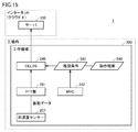
- FIG. 15 is a diagram showing an example of a system configuration of information processing system 1 according to the fourth embodiment.
- the information processing system 1 includes an information processing apparatus 100 and a plurality of machine tools 200.
- the machine tool 200 is, for example, the MVX5000 series manufactured by DMG MORI.
- Machine tool 200 according to the present embodiment has a recommendation function for recommending control parameter candidates to be set in itself.
- a recommended function by MVC (Machine Vibration Control) manufactured by DMG MORI is employed.
- MVC Machine Vibration Control
- MVC automatically recommends recommended conditions for reducing chatter to the user based on the detection of unintentional vibration (hereinafter also referred to as “chatter”) that occurs between the tool and the workpiece during workpiece machining.
- the machine tool 200 sets a control parameter corresponding to the selected recommended condition. This optimizes the control parameters and reduces chatter.
- the information processing apparatus 100 collects recommended conditions selected from MVC recommended conditions from various machine tools 200. More specifically, the machine tool 200 includes a CELOS 240 that is an operating system, and the CELOS 240 acquires a recommended condition 245 by the MVC 242 and an operation result 246 by adopting the recommended condition 245 from the MVC 242.
- the operation result 246 indicates whether or not chatter has been reduced by adopting the recommended condition 245, and is represented by, for example, what percentage can be reduced.
- the acceleration sensor 207 acquires the acceleration of the spindle of the machine tool 200 as vibration data.
- An FFT (Fast Fourier Transform) unit 241 performs fast Fourier transform on the vibration data obtained from the acceleration sensor 207. As a result, the vibration data is frequency-resolved. The result of the Fourier transform is output to CELOS 240.
- the CELOS 240 transmits the detection information by the acceleration sensor 207, the recommended condition 245, and the operation result 246 to the information processing apparatus 100.
- the information processing apparatus 100 collects these pieces of information as collected data from various machine tools 200, associates the detection information, the recommended conditions 245, and the operation results 246 and accumulates these pieces of information in the database 124.
- the information processing apparatus 100 performs machine learning on the type of the operation result 246 for the correlation between the accumulated detection information, the recommended condition 245, and the operation result 246. Thereby, the information processing apparatus 100 can estimate the cutting conditions for reducing chatter more accurately, and can improve the cutting efficiency.
- the information processing apparatus 100 sets the detection information by the acceleration sensor 207, the recommended condition 245 selected from the recommended candidates, and the control parameters based on the recommended condition 245 in the machine tool 200.
- An operation result 246 indicating whether or not chatter has been reduced is received from various machine tools 200 as collected data.
- the information processing apparatus 100 stores the collected data received from the machine tool 200 in the database 124. Thereafter, the information processing apparatus 100 performs machine learning on the correlation between the detection information by the acceleration sensor 207, the recommended condition 245, and the operation result 246 based on the collected data accumulated in the database 124.
- the information processing apparatus 100 uses tool information (for example, manufacturer and tool type), workpiece type, and cutting conditions (for example, spindle speed, cutting width, cutting depth, feed, etc.) in the machining process when using the MVC 242. ), Various sensor information mainly based on acceleration (for example, frequency, peak vibration), machine state (for example, each axis coordinate, axis load), and the like may be collected.
- the information processing apparatus 100 according to the first embodiment collects information detected by sensors in the machine tool 200 and part information related to maintenance parts of the machine tool 200.
- the information processing apparatus 100 according to the fifth embodiment collects detection information by sensors in the machine tool 200 and correction information on control parameters set in the machine tool 200.
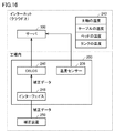
- FIG. 16 is a diagram showing an example of the system configuration of the information processing system 1 according to the fifth embodiment.
- the information processing system 1 includes an information processing apparatus 100 and a plurality of machine tools 200.
- the machine tool 200 is, for example, a DMU series or NTX series manufactured by DMG MORI.
- Machine tool 200 according to the present embodiment includes an interface 248 for connecting correction device 250 for correcting the control parameter of machine tool 200.
- the correction device 250 is “3D Quick Set”. “3D Quick Set” measures the geometric intersection of the swivel axes using a touch probe and a true sphere, and automatically corrects the error of the spindle of the machine tool 200 and the swivel center of the table based on the measurement result. It is a tool kit.
- the information processing apparatus 100 collects control parameter correction information by the correction apparatus 250 from various machine tools 200. More specifically, the machine tool 200 includes a CELOS 240 that is an operating system. The CELOS 240 acquires control parameter correction information by the correction device 250 from the correction device 250 via the interface 248. The CELOS 240 transmits the correction information acquired from the correction device 250 to the information processing device 100.
- the machine tool 200 includes a CELOS 240 that is an operating system.
- the CELOS 240 acquires control parameter correction information by the correction device 250 from the correction device 250 via the interface 248.
- the CELOS 240 transmits the correction information acquired from the correction device 250 to the information processing device 100.
- the temperature sensor 206 detects the maintenance temperature of the components in the machine tool 200.
- the temperature sensor 206 is provided for each temperature detection target component.
- the temperature sensor 206 detects, for example, the temperature of the spindle, the temperature of the table for holding the workpiece, the temperature of the bed, the temperature of the tank, and the like.
- the temperature detected by the temperature sensor 206 is transmitted to the information processing apparatus 100 as detection information 243.
- the information processing apparatus 100 collects the detection information 243 by the temperature sensor 206 and the correction information by the correction apparatus 250 as collected data from various machine tools 200, and associates the correction information by the correction apparatus 250 with these information. Are stored in the database 124. Thereafter, the information processing apparatus 100 performs machine learning on the correlation between the accumulated detection information and the correction information. Preferably, the correlation is machine-learned for each type of machine tool 200 and each type of maintenance part. Thereby, the information processing apparatus 100 can construct an algorithm that can estimate that the error is increasing based on the detection information of the temperature sensor before the measurement, and can feed back to the machine tool 200. . Further, the machine tool 200 can accurately predict deterioration in accuracy based on detection information from the temperature sensor, and can estimate the timing of using the correction device 250.
- the information processing apparatus 100 receives detection information from the temperature sensor 206 and control parameter correction information from the correction apparatus 250 from various machine tools 200 as collected data.
- the information processing apparatus 100 stores the collected data received from the machine tool 200 in the database 124. Thereafter, the information processing apparatus 100 performs machine learning on the correlation between the detection information by the temperature sensor 206 and the correction information by the correction apparatus 250 based on the collected data accumulated in the database 124.
- the information processing apparatus 100 may further collect operation information indicating the operation status of the machine tool 200.
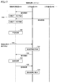
- FIG. 17 is a sequence diagram showing a data flow between information processing apparatus 100 and machine tools 200A and 200B according to the sixth embodiment.
- step S80 the information processing apparatus 100 periodically receives detection information from the sensor of the machine tool 200A as collected data from the machine tool 200A.
- the collected data received is stored in the database 124 (see FIG. 3).
- the information processing apparatus 100 periodically receives detection information from the sensor of the machine tool 200B as collected data from the machine tool 200B.
- the collected data received is stored in the database 124 (see FIG. 3).
- step S82 the information processing apparatus 100 executes a learning process for the collected data stored in the database 124 based on receiving a learning instruction from the user.
- the information processing apparatus 100 learns the normal range of detection information for each type of sensor.
- the information processing apparatus 100 calculates an average value and a standard deviation of detection information for each type of sensor, and obtains a lower limit value obtained by subtracting a predetermined multiple of the standard deviation from the average value, and a standard deviation from the average value. A range between the upper limit value obtained by adding the predetermined multiple is learned as a normal range.
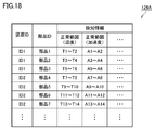
- FIG. 18 is a diagram illustrating an example of a learning result 126A obtained by a learning process performed by the information processing apparatus 100.
- the learning result 126A the normal range of detection information of each sensor is defined for each type of device and each type of component.
- the learning result 126A is stored in, for example, the storage device 120 of the information processing apparatus 100.
- step S84 it is assumed that the machine tool 200A receives an instruction to execute diagnostic processing.
- the user prepares a workpiece of a specific size and a specific material in the machine tool 200A in advance, and executes a self-diagnosis program.
- the machine tool 200A executes the NC program prepared for self-diagnosis and starts machining the workpiece using a specific tool.
- the machine tool 200A monitors the detection information of the sensor during the machining of the workpiece, and collects the detection information.
- the detection information of the collection target includes, for example, motor load fluctuations, spindle temperature fluctuations, coolant temperature fluctuations, spindle vibrations, motor load fluctuations related to the tool trajectory such as the XYAB axis, and XYAB. Includes encoder trajectory data related to the trajectory of the tool such as the axis.
- step S88 the machine tool 200A transmits the detection information collected in step S86 to the information processing apparatus 100.
- the shape of a specific part of the workpiece may be measured by a measurement unit (for example, a touch probe) in the machine tool 200A after the workpiece machining in step S86 is finished, and in this case, the measurement result is further determined by the machine tool. 200A.
- step S90 the information processing apparatus 100 diagnoses the machine tool 200A based on the detection information received from the machine tool 200A. More specifically, the information processing apparatus 100 refers to the learning result 126A obtained in the learning process in step S82 to determine whether or not the type of each piece of detection information is included in the normal range. Based on the result, the machine tool 200A is diagnosed. As an example, the information processing apparatus 100 uses the learning result 126A as the learning result 126A about the vibration state of the machine tool 200A, the temperature fluctuation range of the machine tool 200A, the quadrant projection (backlash) of the machine tool 200A, the operation load of each axis of the machine tool 200A. Compare with specified normal range.
- step S92 the information processing apparatus 100 transmits the medical chart obtained as the diagnosis result in step S90 to the machine tool 200A.
- step S94 the machine tool 200A displays the diagnosis result received from the information processing apparatus 100.
- FIG. 19 is a diagram illustrating an example of a diagnosis result screen 260 displayed on the display 210 of the machine tool 200A.
- the diagnosis result screen 260 shows a determination result indicating the normal level of each detection information.
- a coping method for example, adjustment, parts replacement, manufacturer contact, etc.
- the prediction of the time when the failure occurs is shown from the degree of change compared with the past data.
- the information processing apparatus 100 stores a medical record obtained as a diagnosis result every time the diagnosis process is executed. Thereby, the information processing apparatus 100 can accumulate a large amount of medical records, and can estimate the future failure occurrence probability by machine learning together with the maintenance record.
- the information processing apparatus 100 receives detection information from each of a plurality of sensors in the machine tool 200 as collected data from various machine tools 200.
- the information processing apparatus 100 stores the collected data received from the machine tool 200 in the database 124.
- the information processing apparatus 100 learns the normal range of the detection information for each type of sensor based on the collected data stored in the database 124. Thereafter, when the information processing apparatus 100 receives an instruction to execute diagnosis of the machine tool from an arbitrary machine tool, the information processing apparatus 100 receives detection information from the sensor in the machine tool from the machine tool, and the learning result by the learning process. , It is diagnosed whether each of the received detection information is within the corresponding normal range.
- the information processing apparatus 100 transmits the diagnosis result to the machine tool that is the transmission source of the diagnosis processing execution instruction.
- the accumulated diagnosis results can be used for failure prediction.
- FIG. 20 is a diagram showing an example of a system configuration of information processing system 1 according to the seventh embodiment.
- the information processing system 1 includes, for example, an information processing apparatus 100, machine tools 200A to 200C, a PC 300, and communication terminals 500A to 500C.
- the machine tools 200A to 200C and the PC 300 are connected to each other via the network NW1.
- the information processing apparatus 100 and the machine tools 200A to 200C are not directly connected to the network. Security is ensured by separating the network of the information processing apparatus 100 and the machine tools 200A to 200C.
- the information to be collected is transmitted from the machine tool 200 to the information processing apparatus 100 via the communication terminals 500A to 500C.
- Communication terminal 500A is, for example, a communication adapter.
- MMLink registered trademark
- Communication terminals 500B and 500C are portable terminals such as smartphones and tablets.
- FIG. 21 is a diagram illustrating an example of collected data 125 collected from the machine tool 200 by the information processing apparatus 100.
- the information processing apparatus 100 collects various information indicated by the collected data 125 from the machine tool 200 in addition to the above-described information.
- an information processing method includes a step of communicating with a plurality of machine tools.
- Each of the plurality of machine tools includes a sensor for detecting information on the machine tool as detection information.
- the step of communicating includes a step of receiving, as collected data, part information relating to parts of the machine tool and detection information by the sensor from each of the plurality of machine tools.
- the information processing method further includes: storing the collected data received from each of the plurality of machine tools in a storage unit; and a plurality of the collected data stored in the storage unit based on the plurality of collected data. Learning a correlation between the component information and the information detected by the sensor in the machine tool.
- the collected data includes, from each of the plurality of machine tools, the part information including a replacement timing of the parts of the machine tool and detection information by the sensor until the replacement timing of the parts.
- the learning step learns a correlation between the replacement timing of a part of the machine tool and information detected by a sensor in the machine tool based on the plurality of collected data stored in the storage unit. Includes steps.
- the information processing method when the detection information by the sensor is newly received from any one of the plurality of machine tools and other machine tools, the information is received by referring to the correlation.
- the apparatus further includes a life estimation unit for specifying a part replacement timing corresponding to the detected information and estimating the life of the part based on the specified replacement timing.
- the collected data includes, from each of the plurality of machine tools, the part information including a failure timing of a part of the machine tool and detection information by the sensor until the failure timing of the part.
- the learning step learns a correlation between a failure timing of a part of the machine tool and information detected by a sensor in the machine tool based on the plurality of collected data stored in the storage unit. Includes steps.
- the information processing method when the detection information by the sensor is newly received from any one of the plurality of machine tools and other machine tools, the information is received by referring to the correlation.
- the method further includes the step of identifying the failure timing of the component corresponding to the detected information and determining the replacement timing of the component based on the identified failure timing.
- the information processing method includes a step of communicating with a plurality of machine tools.
- the step of communicating comprises receiving from each of the plurality of machine tools, the contents of an alarm generated in the machine tool and a countermeasure performed on the machine tool when the alarm is generated, as collected data.
- the information processing method further includes the step of storing the collected data received from each of the plurality of machine tools in a storage unit, and the alarm based on the plurality of collected data stored in the storage unit. Learning a correlation between the alarm and a coping method for the alarm for each type.
- the information processing method refers to the correlation when an alarm generated in the machine tool is newly received from any one of the plurality of machine tools and other machine tools.
- the method further includes the step of identifying a coping method for responding to the newly received alarm and outputting the identified coping method.
- the information processing method includes a step of communicating with a plurality of machine tools.
- Each of the plurality of machine tools includes a sensor for detecting information related to the machine tool as detection information, and a recommendation for recommending candidate control parameter recommended conditions for reducing vibration of the spindle of the machine tool.
- the communicating step is performed by setting information detected by the sensor, a recommended condition selected from the candidates, and a control parameter based on the recommended condition in the machine tool from each of the plurality of machine tools. Receiving the result indicating whether the vibration is reduced or not as collected data.
- the information processing method further includes: storing the collected data received from each of the plurality of machine tools in a storage unit; and a plurality of the collected data stored in the storage unit, Learning a correlation between the detection information by the sensor, the recommended condition selected from the candidates, and the result.
- the information processing method includes a step of communicating with a plurality of machine tools.
- Each of the plurality of machine tools includes a sensor for detecting information related to the machine tool as detection information, and an interface for connecting to a correction device for correcting a control parameter of the machine tool.
- the step of communicating includes the step of receiving detection information by the sensor and correction information of the control parameter by the correction device as collected data from each of the plurality of machine tools.
- the information processing method further includes: storing the collected data received from each of the plurality of machine tools in a storage unit; and a plurality of the collected data stored in the storage unit, Learning a correlation between the detection information by the sensor and the correction information by the correction device.
- the information processing method includes a step of communicating with a plurality of machine tools.
- Each of the plurality of machine tools includes a plurality of sensors for detecting different information regarding the machine tool.
- the step of communicating includes a step of receiving detection information from each of the plurality of sensors in the machine tool as collected data from each of the plurality of machine tools.
- the information processing method further includes: storing the collected data received from each of the plurality of machine tools in a storage unit; and the plurality of the collected data stored in the storage unit based on the plurality of the collected data.
- a step of learning a normal range of detection information for each type of sensor, and when a diagnosis execution instruction is received from any one of the plurality of machine tools and other machine tools, the above in the machine tool Receiving detection information from a plurality of sensors from the machine tool, referring to a learning result in the learning step, diagnosing whether each of the received detection information is within a corresponding normal range; Transmitting the diagnosis result in the diagnosing step to the machine tool that is the transmission source of the execution instruction.
- the information processing system includes an information processing device and a plurality of machine tools capable of communicating with the information processing device.
- Each of the plurality of machine tools includes a sensor for detecting information on the machine tool as detection information.
- the information processing apparatus includes a communication unit for receiving, as collected data, part information related to a part of the machine tool and detection information by the sensor from each of the plurality of machine tools, and each of the plurality of machine tools.
- a storage unit for storing the collected data received from the machine, and based on a plurality of the collected data stored in the storage unit, part information of the machine tool and detection information by a sensor in the machine tool And a learning unit for learning the correlation between them.
- the information processing apparatus includes a communication unit for communicating with a plurality of machine tools.
- Each of the plurality of machine tools includes a sensor for detecting information on the machine tool as detection information.
- the communication unit receives, as collected data, part information related to parts of the machine tool and detection information by the sensor from each of the plurality of machine tools.
- the information processing apparatus further includes a storage unit for storing the collected data received from each of the plurality of machine tools, and a plurality of the collected data stored in the storage unit.
- a learning unit for learning a correlation between the component information and the detection information by the sensor in the machine tool.
- 1 information processing system 100 information processing apparatus, 101, 201 control apparatus, 102, 202 ROM, 103, 203 RAM, 104, 204 communication interface, 105, 205 display interface, 106, 209 input interface, 110, 210 display, 111 Input device, 120, 220 storage device, 122 information processing program, 124, 124A, 124B database, 125, 125A-125P collected data, 126 correlation, 126A learning result, 152 communication unit, 154 learning unit, 156 life estimation unit 158, failure determination unit, 200A to 200D machine tool, 206 temperature sensor, 207 acceleration sensor, 208 current sensor, 222 control program, 230, 2 1 input area, 232 registration button, 233 cancel button, 241 FFT section, 243 detection information, 245 recommended conditions, 246 operation result, 248 interface, 250 correction device, 260 diagnostic result screen, 300A, 300B, 500A-500C communication terminal, 401 Router.
Landscapes
- Engineering & Computer Science (AREA)
- Physics & Mathematics (AREA)
- General Physics & Mathematics (AREA)
- Automation & Control Theory (AREA)
- Artificial Intelligence (AREA)
- Mechanical Engineering (AREA)
- Manufacturing & Machinery (AREA)
- Evolutionary Computation (AREA)
- Computer Vision & Pattern Recognition (AREA)
- Medical Informatics (AREA)
- Health & Medical Sciences (AREA)
- Software Systems (AREA)
- Human Computer Interaction (AREA)
- Quality & Reliability (AREA)
- Life Sciences & Earth Sciences (AREA)
- Bioinformatics & Cheminformatics (AREA)
- Bioinformatics & Computational Biology (AREA)
- Evolutionary Biology (AREA)
- General Engineering & Computer Science (AREA)
- Mathematical Physics (AREA)
- Numerical Control (AREA)
- General Factory Administration (AREA)
- Testing And Monitoring For Control Systems (AREA)
- Management, Administration, Business Operations System, And Electronic Commerce (AREA)
- Machine Tool Sensing Apparatuses (AREA)
Abstract
L'invention concerne un procédé de traitement d'informations qui permet une utilisation efficace de diverses informations collectées à partir d'une machine-outil. Le procédé de traitement d'informations comprend une étape (S10) pour communiquer avec une pluralité de machines-outils. La pluralité de machines-outils comprennent chacune un capteur pour détecter, en tant qu'informations de détection, des informations concernant la machine-outil correspondante. L'étape (S10) de communication comprend une étape pour recevoir, en tant que données collectées à partir de chacune de la pluralité de machines-outils, des informations de composant concernant un composant de la machine-outil et les informations de détection détectées par le capteur. Le procédé de traitement d'informations comprend en outre des étapes (S20A, S20B) pour stocker, dans une unité de stockage, les données collectées reçues de la pluralité de machines-outils, et une étape (S32) pour apprendre des corrélations entre les informations de composant concernant les machines-outils et les informations de détection détectées par les capteurs des machines-outils sur la base d'une pluralité des ensembles de données collectés stockés dans l'unité de stockage.
Priority Applications (4)
| Application Number | Priority Date | Filing Date | Title |
|---|---|---|---|
| US16/467,901 US11897068B2 (en) | 2016-12-09 | 2017-08-24 | Information processing method, information processing system, and information processing device |
| KR1020197019126A KR102407484B1 (ko) | 2016-12-09 | 2017-08-24 | 정보 처리 방법, 정보 처리 시스템, 및 정보 처리 장치 |
| EP17878001.1A EP3553613B1 (fr) | 2016-12-09 | 2017-08-24 | Méthode de traitement de l'apprentissage et de diagnostic pour une pluralité de machines-outils |
| CN201780075823.2A CN110088699B (zh) | 2016-12-09 | 2017-08-24 | 信息处理方法、信息处理系统以及信息处理装置 |
Applications Claiming Priority (2)
| Application Number | Priority Date | Filing Date | Title |
|---|---|---|---|
| JP2016239830A JP6675297B2 (ja) | 2016-12-09 | 2016-12-09 | 情報処理方法、情報処理システム、および情報処理装置 |
| JP2016-239830 | 2016-12-09 |
Publications (1)
| Publication Number | Publication Date |
|---|---|
| WO2018105175A1 true WO2018105175A1 (fr) | 2018-06-14 |
Family
ID=62491471
Family Applications (1)
| Application Number | Title | Priority Date | Filing Date |
|---|---|---|---|
| PCT/JP2017/030288 Ceased WO2018105175A1 (fr) | 2016-12-09 | 2017-08-24 | Procédé de traitement d'informations, système de traitement d'informations et dispositif de traitement d'informations |
Country Status (6)
| Country | Link |
|---|---|
| US (1) | US11897068B2 (fr) |
| EP (1) | EP3553613B1 (fr) |
| JP (1) | JP6675297B2 (fr) |
| KR (1) | KR102407484B1 (fr) |
| CN (1) | CN110088699B (fr) |
| WO (1) | WO2018105175A1 (fr) |
Cited By (5)
| Publication number | Priority date | Publication date | Assignee | Title |
|---|---|---|---|---|
| JP2019220164A (ja) * | 2018-06-21 | 2019-12-26 | 高聖精密機電股▲分▼有限公司Cosen Mechatronics Co.,Ltd | スマート調整システム及びその方法 |
| JP2020015148A (ja) * | 2018-07-26 | 2020-01-30 | 三菱マテリアル株式会社 | 切削管理システム、及び切削管理方法 |
| WO2020161865A1 (fr) * | 2019-02-07 | 2020-08-13 | ギガフォトン株式会社 | Procédé d'apprentissage automatique, dispositif de gestion d'article consommable et support lisible par ordinateur |
| JP2020138265A (ja) * | 2019-02-27 | 2020-09-03 | ファナック株式会社 | びびり振動判定装置、機械学習装置及びシステム |
| JP6837622B1 (ja) * | 2020-07-10 | 2021-03-03 | 三菱電機株式会社 | 診断装置、診断方法及びプログラム |
Families Citing this family (32)
| Publication number | Priority date | Publication date | Assignee | Title |
|---|---|---|---|---|
| JP6603272B2 (ja) * | 2017-07-18 | 2019-11-06 | ファナック株式会社 | 情報収集装置及び情報収集方法 |
| JP6589018B1 (ja) * | 2018-07-03 | 2019-10-09 | Dmg森精機株式会社 | 測定方法 |
| JP7216986B2 (ja) * | 2018-08-27 | 2023-02-02 | 有限会社藤川樹脂 | 画像生成装置、画像生成表示システム及び画像生成方法 |
| JP6893750B2 (ja) * | 2018-09-14 | 2021-06-23 | 株式会社日本製鋼所 | 射出成形機、射出成形機の状態報知システム、射出成形機の状態報知方法 |
| JP2020060862A (ja) * | 2018-10-05 | 2020-04-16 | ファナック株式会社 | 工作機械、及び工作機械の認証システム |
| JP2020066062A (ja) * | 2018-10-22 | 2020-04-30 | ファナック株式会社 | 異常監視装置および異常判定方法 |
| WO2020149316A1 (fr) * | 2019-01-15 | 2020-07-23 | 株式会社山本金属製作所 | Système de traitement externe pour une machine-outil |
| JP6806384B2 (ja) * | 2019-01-16 | 2021-01-06 | 株式会社三葉電熔社 | 故障予測システム |
| JP2020126430A (ja) * | 2019-02-04 | 2020-08-20 | ファナック株式会社 | 保守時期予測装置 |
| JP2020135007A (ja) * | 2019-02-13 | 2020-08-31 | セイコーエプソン株式会社 | 情報処理装置、学習装置及び学習済モデル |
| JP7233947B2 (ja) * | 2019-02-13 | 2023-03-07 | Dgshape株式会社 | デンタル加工機のエラー履歴表示システム |
| JP7132166B2 (ja) * | 2019-04-04 | 2022-09-06 | ファナック株式会社 | 数値制御装置及び数値制御システム |
| JP7000376B2 (ja) * | 2019-04-23 | 2022-01-19 | ファナック株式会社 | 機械学習装置、予測装置、及び制御装置 |
| JP6875461B2 (ja) * | 2019-07-05 | 2021-05-26 | 株式会社日立製作所 | 機械加工管理方法及び機械加工管理システム |
| US12265932B2 (en) | 2019-09-23 | 2025-04-01 | Booz Allen Hamilton Inc. | System and method for assessing an operating condition of an asset |
| JP7317662B2 (ja) * | 2019-10-24 | 2023-07-31 | 大阪瓦斯株式会社 | 需要予測システム |
| JP7441652B2 (ja) * | 2020-01-10 | 2024-03-01 | ユニ・チャーム株式会社 | 吸収性物品の製造装置に関する推定装置、吸収性物品の製造装置に関する推定方法、および吸収性物品の製造装置に関するプログラム |
| CN115210024A (zh) * | 2020-03-05 | 2022-10-18 | 发那科株式会社 | 机器学习装置、预测装置以及控制装置 |
| JP7487503B2 (ja) * | 2020-03-16 | 2024-05-21 | 株式会社ジェイテクト | びびり予測システム |
| US20230191513A1 (en) * | 2020-05-25 | 2023-06-22 | Fanuc Corporation | Tool diagnostic device |
| JP7551967B2 (ja) * | 2020-06-08 | 2024-09-18 | 株式会社三葉電熔社 | 装置状態監視システム |
| US20230305520A1 (en) * | 2020-06-24 | 2023-09-28 | Fanuc Corporation | Tool diagnostic device and tool diagnostic method |
| JP6842591B1 (ja) * | 2020-07-07 | 2021-03-17 | Dmg森精機株式会社 | 工作機械、工作機械の制御方法、および、工作機械の制御プログラム |
| DE102020128369A1 (de) * | 2020-10-28 | 2022-04-28 | Leybold Gmbh | Verfahren zum Betrieb einer Scroll-Pumpe sowie Scroll-Pumpe |
| CN112399367A (zh) * | 2020-11-06 | 2021-02-23 | 哈尔滨师范大学 | 一种抗干扰的大型设备结构安全检测方法 |
| JP7633031B2 (ja) * | 2021-01-29 | 2025-02-19 | 三菱重工業株式会社 | 対処法提示システム、対処法提示方法およびプログラム |
| JP6990332B1 (ja) | 2021-02-25 | 2022-01-14 | Dmg森精機株式会社 | 工作機械 |
| JP7653815B2 (ja) * | 2021-03-19 | 2025-03-31 | 大阪瓦斯株式会社 | 給湯器の故障推定システム |
| JP7699517B2 (ja) * | 2021-10-05 | 2025-06-27 | 株式会社荏原製作所 | 情報処理装置、推論装置、機械学習装置、情報処理方法、推論方法、及び、機械学習方法 |
| JP7829354B2 (ja) * | 2022-03-03 | 2026-03-13 | 三菱電機株式会社 | 水処理制御支援システム、水処理制御支援方法、および水処理制御支援プログラム |
| WO2025142082A1 (fr) * | 2023-12-25 | 2025-07-03 | 株式会社デンソー | Procédé, système et programme de gestion de composants |
| KR102829216B1 (ko) * | 2024-06-05 | 2025-07-09 | 주식회사 투비콤 | 현장 설비의 상태를 진단하는 진단 어댑터 장치 |
Citations (9)
| Publication number | Priority date | Publication date | Assignee | Title |
|---|---|---|---|---|
| WO2000012259A1 (fr) | 1998-08-28 | 2000-03-09 | Mori Seiki Co., Ltd. | Preparation de base de donnees d'informations sur un outillage de machine d'usinage a commande numerique et dispositif associe de gestion d'outillage |
| WO2002003156A1 (fr) | 2000-06-30 | 2002-01-10 | Mori Seiki Co., Ltd. | Systeme de support d'usinage a commande numerique |
| JP2002530768A (ja) * | 1998-11-25 | 2002-09-17 | フェデラル−モーグル コーポレイション | 診断ルールベースツール状態モニタシステム |
| JP2003177815A (ja) | 2001-12-07 | 2003-06-27 | Komatsu Ltd | 産業機械の保全システム |
| JP2004086338A (ja) * | 2002-08-23 | 2004-03-18 | Toshiba Corp | 警報制御処理装置 |
| JP2015153914A (ja) * | 2014-02-14 | 2015-08-24 | オムロン株式会社 | 品質管理装置、品質管理方法、およびプログラム |
| US20150323425A1 (en) * | 2014-05-12 | 2015-11-12 | Samsung Techwin Co., Ltd. | System and method for generating facility abnormality prediction model, and computer-readable recording medium storing program for executing the method |
| JP2015203646A (ja) * | 2014-04-15 | 2015-11-16 | 三菱重工業株式会社 | 工作機械の診断方法及びシステム |
| JP5992087B1 (ja) | 2015-12-28 | 2016-09-14 | ファナック株式会社 | 機械の保全計画を作成する予防保全管理システム |
Family Cites Families (42)
| Publication number | Priority date | Publication date | Assignee | Title |
|---|---|---|---|---|
| EP0228151B1 (fr) * | 1985-08-27 | 1993-12-22 | HENKEL CORPORATION (a Delaware Corp.) | Solutions aqueuses acides de phosphatation pour leur utilisation dans un procédé de phosphatation de surfaces métalliques |
| JP2821189B2 (ja) * | 1989-09-01 | 1998-11-05 | 株式会社日立製作所 | 学習型意思決定支援システム |
| KR920002268A (ko) * | 1990-07-17 | 1992-02-28 | 유끼노리 가까즈 | 인텔리젠트가공장치 |
| US5631825A (en) * | 1993-09-29 | 1997-05-20 | Dow Benelux N.V. | Operator station for manufacturing process control system |
| BR9709624A (pt) * | 1996-05-31 | 1999-08-10 | Baker Hughes Inc | Método e aparelho para controle de máquinas de flotação de espuma |
| JPH10187228A (ja) * | 1996-12-20 | 1998-07-14 | Toshiba Corp | プラント運転支援装置 |
| US6295510B1 (en) * | 1998-07-17 | 2001-09-25 | Reliance Electric Technologies, Llc | Modular machinery data collection and analysis system |
| US6278920B1 (en) * | 2000-06-19 | 2001-08-21 | James O. Hebberd | Method for analyzing and forecasting component replacement |
| WO2001098849A2 (fr) | 2000-06-19 | 2001-12-27 | Dow Global Technologies Inc. | Systeme de diagnostique d'equipement rotatif et unite de commande adaptive |
| JP3969494B2 (ja) * | 2004-08-31 | 2007-09-05 | 三菱電機株式会社 | 車載電子制御装置 |
| JP4944391B2 (ja) * | 2005-05-11 | 2012-05-30 | 富士通株式会社 | メッセージ異常自動判別装置、方法、及びプログラム |
| US20080097945A1 (en) * | 2006-08-09 | 2008-04-24 | The University Of North Carolina At Chapel Hill | Novelty detection systems, methods and computer program products for real-time diagnostics/prognostics in complex physical systems |
| JP4423617B2 (ja) * | 2007-01-10 | 2010-03-03 | 株式会社日立製作所 | プラント制御装置 |
| US7667596B2 (en) * | 2007-02-16 | 2010-02-23 | Panasonic Corporation | Method and system for scoring surveillance system footage |
| JP2009070071A (ja) * | 2007-09-12 | 2009-04-02 | Toshiba Corp | 学習型プロセス異常診断装置、およびオペレータ判断推測結果収集装置 |
| CN101359228B (zh) * | 2008-09-09 | 2011-04-20 | 张东来 | 基于驱动端电流变化的电磁控制元件故障诊断方法及装置 |
| JP5182178B2 (ja) * | 2009-03-18 | 2013-04-10 | ソニー株式会社 | 情報処理装置及び情報処理方法 |
| JP5375396B2 (ja) * | 2009-07-17 | 2013-12-25 | 富士ゼロックス株式会社 | 消耗品管理システムおよび画像形成装置 |
| JP5363927B2 (ja) * | 2009-09-07 | 2013-12-11 | 株式会社日立製作所 | 異常検知・診断方法、異常検知・診断システム、及び異常検知・診断プログラム |
| JP2011145846A (ja) * | 2010-01-14 | 2011-07-28 | Hitachi Ltd | 異常検知方法、異常検知システム、及び異常検知プログラム |
| JP5473651B2 (ja) | 2010-02-08 | 2014-04-16 | キヤノン株式会社 | 管理システム、監視装置及び情報処理方法 |
| US9836110B2 (en) * | 2010-02-25 | 2017-12-05 | Echostar Technologies L.L.C. | Apparatus, systems and methods for learning a critical voltage of a microprocessor control unit |
| JP5545026B2 (ja) * | 2010-05-18 | 2014-07-09 | Dmg森精機株式会社 | 電子機器、および制限解除方法 |
| CN102156447B (zh) * | 2010-12-03 | 2013-08-14 | 中冶南方工程技术有限公司 | 基于基础自动化的工厂级设备管理和报警系统及方法 |
| US9467500B2 (en) * | 2012-08-09 | 2016-10-11 | Rockwell Automation Technologies, Inc. | Remote industrial monitoring using a cloud infrastructure |
| US9561810B2 (en) * | 2013-01-11 | 2017-02-07 | International Business Machines Corporation | Large-scale multi-detector predictive modeling |
| AR095272A1 (es) * | 2013-03-14 | 2015-09-30 | Fisher Controls Int Llc | Pronóstico de válvula en función de análisis de laboratorio |
| WO2014145977A1 (fr) * | 2013-03-15 | 2014-09-18 | Bates Alexander B | Système et procédés de détection automatisée de défaillance d'actifs d'usine |
| EP3019920B1 (fr) * | 2013-07-13 | 2022-03-30 | Festo SE & Co. KG | Unité de détection de données et système d'automatisation |
| JP6144582B2 (ja) * | 2013-09-13 | 2017-06-07 | Dmg森精機株式会社 | Nc工作機械の操作装置 |
| JP6216242B2 (ja) * | 2013-12-13 | 2017-10-18 | 株式会社日立ハイテクノロジーズ | 異常検知方法およびその装置 |
| JP6282148B2 (ja) * | 2014-03-17 | 2018-02-21 | Dmg森精機株式会社 | 工作機械 |
| AU2015247437B2 (en) * | 2014-04-17 | 2018-12-20 | Lockheed Martin Corporation | Prognostics and health management system |
| US10139311B2 (en) | 2014-09-26 | 2018-11-27 | Palo Alto Research Center Incorporated | Computer-implemented method and system for machine tool damage assessment, prediction, and planning in manufacturing shop floor |
| JP6360432B2 (ja) * | 2014-12-16 | 2018-07-18 | Dmg森精機株式会社 | 段付工具の寿命管理装置 |
| JP6457257B2 (ja) * | 2014-12-18 | 2019-01-23 | Dmg森精機株式会社 | フライス工具、及びこれを用いた加工方法 |
| US20160245686A1 (en) * | 2015-02-23 | 2016-08-25 | Biplab Pal | Fault detection in rotor driven equipment using rotational invariant transform of sub-sampled 3-axis vibrational data |
| CN104612957A (zh) * | 2015-02-02 | 2015-05-13 | 中国石油集团川庆钻探工程有限公司长庆井下技术作业公司 | 一种压裂泵车液力端在线监测系统 |
| JP5937727B1 (ja) * | 2015-05-22 | 2016-06-22 | Dmg森精機株式会社 | 工具摩耗評価装置 |
| JP5997330B1 (ja) | 2015-07-31 | 2016-09-28 | ファナック株式会社 | 主軸交換の要否を判定できる機械学習装置、主軸交換判定装置、制御装置、工作機械及び生産システム、並びに機械学習方法 |
| CN105384015A (zh) * | 2015-12-16 | 2016-03-09 | 苏州大学 | 一种基于人脸识别和智能推荐的电梯控制系统 |
| JP6031202B1 (ja) * | 2016-01-29 | 2016-11-24 | ファナック株式会社 | 製造機械の異常の原因を発見するセル制御装置 |
-
2016
- 2016-12-09 JP JP2016239830A patent/JP6675297B2/ja active Active
-
2017
- 2017-08-24 US US16/467,901 patent/US11897068B2/en active Active
- 2017-08-24 EP EP17878001.1A patent/EP3553613B1/fr active Active
- 2017-08-24 WO PCT/JP2017/030288 patent/WO2018105175A1/fr not_active Ceased
- 2017-08-24 KR KR1020197019126A patent/KR102407484B1/ko active Active
- 2017-08-24 CN CN201780075823.2A patent/CN110088699B/zh active Active
Patent Citations (9)
| Publication number | Priority date | Publication date | Assignee | Title |
|---|---|---|---|---|
| WO2000012259A1 (fr) | 1998-08-28 | 2000-03-09 | Mori Seiki Co., Ltd. | Preparation de base de donnees d'informations sur un outillage de machine d'usinage a commande numerique et dispositif associe de gestion d'outillage |
| JP2002530768A (ja) * | 1998-11-25 | 2002-09-17 | フェデラル−モーグル コーポレイション | 診断ルールベースツール状態モニタシステム |
| WO2002003156A1 (fr) | 2000-06-30 | 2002-01-10 | Mori Seiki Co., Ltd. | Systeme de support d'usinage a commande numerique |
| JP2003177815A (ja) | 2001-12-07 | 2003-06-27 | Komatsu Ltd | 産業機械の保全システム |
| JP2004086338A (ja) * | 2002-08-23 | 2004-03-18 | Toshiba Corp | 警報制御処理装置 |
| JP2015153914A (ja) * | 2014-02-14 | 2015-08-24 | オムロン株式会社 | 品質管理装置、品質管理方法、およびプログラム |
| JP2015203646A (ja) * | 2014-04-15 | 2015-11-16 | 三菱重工業株式会社 | 工作機械の診断方法及びシステム |
| US20150323425A1 (en) * | 2014-05-12 | 2015-11-12 | Samsung Techwin Co., Ltd. | System and method for generating facility abnormality prediction model, and computer-readable recording medium storing program for executing the method |
| JP5992087B1 (ja) | 2015-12-28 | 2016-09-14 | ファナック株式会社 | 機械の保全計画を作成する予防保全管理システム |
Non-Patent Citations (1)
| Title |
|---|
| See also references of EP3553613A4 |
Cited By (13)
| Publication number | Priority date | Publication date | Assignee | Title |
|---|---|---|---|---|
| JP2019220164A (ja) * | 2018-06-21 | 2019-12-26 | 高聖精密機電股▲分▼有限公司Cosen Mechatronics Co.,Ltd | スマート調整システム及びその方法 |
| JP2020015148A (ja) * | 2018-07-26 | 2020-01-30 | 三菱マテリアル株式会社 | 切削管理システム、及び切削管理方法 |
| CN113261166B (zh) * | 2019-02-07 | 2023-07-14 | 极光先进雷射株式会社 | 机器学习方法、消耗品管理装置和计算机可读介质 |
| CN113261166A (zh) * | 2019-02-07 | 2021-08-13 | 极光先进雷射株式会社 | 机器学习方法、消耗品管理装置和计算机可读介质 |
| JPWO2020161865A1 (ja) * | 2019-02-07 | 2021-12-09 | ギガフォトン株式会社 | 機械学習方法、消耗品管理装置、及びコンピュータ可読媒体 |
| WO2020161865A1 (fr) * | 2019-02-07 | 2020-08-13 | ギガフォトン株式会社 | Procédé d'apprentissage automatique, dispositif de gestion d'article consommable et support lisible par ordinateur |
| US11822324B2 (en) | 2019-02-07 | 2023-11-21 | Gigaphoton Inc. | Machine learning method, consumable management apparatus, and computer readable medium |
| JP7428667B2 (ja) | 2019-02-07 | 2024-02-06 | ギガフォトン株式会社 | 機械学習方法、消耗品管理装置、及びコンピュータ可読媒体 |
| JP2020138265A (ja) * | 2019-02-27 | 2020-09-03 | ファナック株式会社 | びびり振動判定装置、機械学習装置及びシステム |
| US11782414B2 (en) | 2019-02-27 | 2023-10-10 | Fanuc Corporation | Chatter vibration determination device, machine learning device, and system |
| JP6837622B1 (ja) * | 2020-07-10 | 2021-03-03 | 三菱電機株式会社 | 診断装置、診断方法及びプログラム |
| WO2022009434A1 (fr) * | 2020-07-10 | 2022-01-13 | 三菱電機株式会社 | Dispositif de diagnostic, procédé de diagnostic et programme |
| US11669068B2 (en) | 2020-07-10 | 2023-06-06 | Mitsubishi Electric Corporation | Diagnostic device, diagnostic method, and recording medium |
Also Published As
| Publication number | Publication date |
|---|---|
| KR102407484B1 (ko) | 2022-06-13 |
| KR20190093604A (ko) | 2019-08-09 |
| JP2018097494A (ja) | 2018-06-21 |
| CN110088699A (zh) | 2019-08-02 |
| US20200061768A1 (en) | 2020-02-27 |
| EP3553613A1 (fr) | 2019-10-16 |
| JP6675297B2 (ja) | 2020-04-01 |
| CN110088699B (zh) | 2022-06-28 |
| EP3553613B1 (fr) | 2024-02-28 |
| EP3553613A4 (fr) | 2020-12-23 |
| US11897068B2 (en) | 2024-02-13 |
Similar Documents
| Publication | Publication Date | Title |
|---|---|---|
| JP6675297B2 (ja) | 情報処理方法、情報処理システム、および情報処理装置 | |
| US11262744B2 (en) | Diagnostic service system and diagnostic method using network | |
| US10942506B2 (en) | Systems and methods for a multi-purpose sensing device for industrial automation equipment | |
| US20210003482A1 (en) | Diagnostic service system and diagnostic method using network | |
| CN110394688B (zh) | 基于边缘计算的机床状态监测方法 | |
| US11307117B2 (en) | System and method for interpretation and analysis of manufacturing activity | |
| KR100599990B1 (ko) | 작업기계의 메인티넌스시스템 | |
| CN110187694A (zh) | 故障预测装置以及机器学习装置 | |
| JP6568167B2 (ja) | 異常検知装置及び機械学習装置 | |
| JP2003177815A (ja) | 産業機械の保全システム | |
| JP2010146537A (ja) | 人工知能化した加工支援監視方法と人工知能化した加工支援監視システム | |
| US20180099413A1 (en) | Robot system and maintenance method for tracking information of module | |
| JP7154100B2 (ja) | 工作機械の加工異常検出装置 | |
| JP2018088177A (ja) | 情報処理装置、情報処理システム、情報処理方法、および情報処理プログラム | |
| KR20220039283A (ko) | 외부장치를 이용한 절삭 공구 파손 감지 및 교체시기 처리시스템 및 방법 | |
| EP3514641A1 (fr) | Système de gestion et de surveillance d'une pluralité de machines-outils à commande numérique | |
| WO2021042233A1 (fr) | Système de diagnostic à distance, appareil et procédé pour outil électrique | |
| JP7674388B2 (ja) | 支援装置及び機械システム | |
| KR102006125B1 (ko) | 모바일 단말기를 이용한 plc 원격제어 및 모니터링 시스템 및 그 방법 | |
| EP3432236A1 (fr) | Procédé et système de réglage automatique d'un phare d'un véhicule | |
| WO2021177238A1 (fr) | Dispositif de commande | |
| US11675347B2 (en) | Industrial machine monitoring device | |
| EP3818421B1 (fr) | Système et procédé de gestion à distance de la configuration de machines industrielles | |
| KR20230046833A (ko) | 공구 진단 시스템 | |
| WO2024154275A1 (fr) | Dispositif de commande et support d'enregistrement lisible par ordinateur |
Legal Events
| Date | Code | Title | Description |
|---|---|---|---|
| DPE1 | Request for preliminary examination filed after expiration of 19th month from priority date (pct application filed from 20040101) | ||
| 121 | Ep: the epo has been informed by wipo that ep was designated in this application |
Ref document number: 17878001 Country of ref document: EP Kind code of ref document: A1 |
|
| NENP | Non-entry into the national phase |
Ref country code: DE |
|
| ENP | Entry into the national phase |
Ref document number: 20197019126 Country of ref document: KR Kind code of ref document: A |
|
| ENP | Entry into the national phase |
Ref document number: 2017878001 Country of ref document: EP Effective date: 20190709 |