WO2018105228A1 - Dispositif de traitement d'image, dispositif d'affichage, procédé de commande de dispositif de traitement d'image et programme de commande - Google Patents
Dispositif de traitement d'image, dispositif d'affichage, procédé de commande de dispositif de traitement d'image et programme de commande Download PDFInfo
- Publication number
- WO2018105228A1 WO2018105228A1 PCT/JP2017/036609 JP2017036609W WO2018105228A1 WO 2018105228 A1 WO2018105228 A1 WO 2018105228A1 JP 2017036609 W JP2017036609 W JP 2017036609W WO 2018105228 A1 WO2018105228 A1 WO 2018105228A1
- Authority
- WO
- WIPO (PCT)
- Prior art keywords
- area
- image
- sky
- region
- divided
- Prior art date
- Legal status (The legal status is an assumption and is not a legal conclusion. Google has not performed a legal analysis and makes no representation as to the accuracy of the status listed.)
- Ceased
Links
Images








Classifications
-
- H—ELECTRICITY
- H04—ELECTRIC COMMUNICATION TECHNIQUE
- H04N—PICTORIAL COMMUNICATION, e.g. TELEVISION
- H04N1/00—Scanning, transmission or reproduction of documents or the like, e.g. facsimile transmission; Details thereof
- H04N1/40—Picture signal circuits
- H04N1/409—Edge or detail enhancement; Noise or error suppression
- H04N1/4092—Edge or detail enhancement
-
- G—PHYSICS
- G09—EDUCATION; CRYPTOGRAPHY; DISPLAY; ADVERTISING; SEALS
- G09G—ARRANGEMENTS OR CIRCUITS FOR CONTROL OF INDICATING DEVICES USING STATIC MEANS TO PRESENT VARIABLE INFORMATION
- G09G5/00—Control arrangements or circuits for visual indicators common to cathode-ray tube indicators and other visual indicators
- G09G5/36—Control arrangements or circuits for visual indicators common to cathode-ray tube indicators and other visual indicators characterised by the display of a graphic pattern, e.g. using an all-points-addressable [APA] memory
-
- H—ELECTRICITY
- H04—ELECTRIC COMMUNICATION TECHNIQUE
- H04N—PICTORIAL COMMUNICATION, e.g. TELEVISION
- H04N1/00—Scanning, transmission or reproduction of documents or the like, e.g. facsimile transmission; Details thereof
- H04N1/46—Colour picture communication systems
- H04N1/56—Processing of colour picture signals
- H04N1/60—Colour correction or control
- H04N1/62—Retouching, i.e. modification of isolated colours only or in isolated picture areas only
- H04N1/628—Memory colours, e.g. skin or sky
-
- G—PHYSICS
- G09—EDUCATION; CRYPTOGRAPHY; DISPLAY; ADVERTISING; SEALS
- G09G—ARRANGEMENTS OR CIRCUITS FOR CONTROL OF INDICATING DEVICES USING STATIC MEANS TO PRESENT VARIABLE INFORMATION
- G09G2320/00—Control of display operating conditions
- G09G2320/06—Adjustment of display parameters
- G09G2320/0686—Adjustment of display parameters with two or more screen areas displaying information with different brightness or colours
-
- G—PHYSICS
- G09—EDUCATION; CRYPTOGRAPHY; DISPLAY; ADVERTISING; SEALS
- G09G—ARRANGEMENTS OR CIRCUITS FOR CONTROL OF INDICATING DEVICES USING STATIC MEANS TO PRESENT VARIABLE INFORMATION
- G09G2340/00—Aspects of display data processing
-
- G—PHYSICS
- G09—EDUCATION; CRYPTOGRAPHY; DISPLAY; ADVERTISING; SEALS
- G09G—ARRANGEMENTS OR CIRCUITS FOR CONTROL OF INDICATING DEVICES USING STATIC MEANS TO PRESENT VARIABLE INFORMATION
- G09G2354/00—Aspects of interface with display user
-
- G—PHYSICS
- G09—EDUCATION; CRYPTOGRAPHY; DISPLAY; ADVERTISING; SEALS
- G09G—ARRANGEMENTS OR CIRCUITS FOR CONTROL OF INDICATING DEVICES USING STATIC MEANS TO PRESENT VARIABLE INFORMATION
- G09G2360/00—Aspects of the architecture of display systems
- G09G2360/16—Calculation or use of calculated indices related to luminance levels in display data
-
- G—PHYSICS
- G09—EDUCATION; CRYPTOGRAPHY; DISPLAY; ADVERTISING; SEALS
- G09G—ARRANGEMENTS OR CIRCUITS FOR CONTROL OF INDICATING DEVICES USING STATIC MEANS TO PRESENT VARIABLE INFORMATION
- G09G5/00—Control arrangements or circuits for visual indicators common to cathode-ray tube indicators and other visual indicators
- G09G5/02—Control arrangements or circuits for visual indicators common to cathode-ray tube indicators and other visual indicators characterised by the way in which colour is displayed
Definitions
- the following disclosure relates to an image processing apparatus that processes an image.
- Patent Document 1 discloses a display device (image display device) for displaying an object (object) on a screen so as to obtain a stereoscopic effect close to the actual appearance in the natural world. Has been.
- the display device of Patent Document 1 is configured for the purpose of reproducing the appearance of such an object. More specifically, the display device of Patent Document 1 includes image processing means for performing diffusion processing (processing processing) according to the distance from the gazing point to the position of the target object on the image information representing the target object. And image reproducing means for generating pixel information representing each pixel to be displayed on the display screen based on the image information subjected to the diffusion processing.
- image processing means for performing diffusion processing (processing processing) according to the distance from the gazing point to the position of the target object on the image information representing the target object.
- image reproducing means for generating pixel information representing each pixel to be displayed on the display screen based on the image information subjected to the diffusion processing.
- Patent Document 2 discloses a technique for changing the display of the display based on the user's line of sight (how the user looks at the computer display).
- Japanese Patent Publication Japanese Patent Laid-Open No. 9-55959 (published on February 25, 1997)” Japanese Patent Publication “Special Table 2014-532206 Publication (December 4, 2014)”
- An object of one aspect of the present disclosure is to realize an image processing apparatus that generates an image close to an actual appearance in the natural world.
- an image processing apparatus includes a sky area specifying unit that specifies a sky area corresponding to the sky in a display target image, and the sky area specifying unit that specifies the sky area specifying unit. Based on the color of the sky area, when it is determined by the execution determination unit that determines whether or not to perform the blurring process for the sky area and the blur determination process by the execution determination unit, the sky area An image generation unit that generates a post-processing image by performing a blurring process.
- a control method for an image processing device includes a sky region specifying step of specifying a sky region corresponding to the sky in a display target image, and the sky region specifying step.
- An execution feasibility determination step for determining whether to perform blurring processing on the sky region based on the color of the sky region specified in step, and when it is determined that the blurring processing is performed in the execution feasibility determination step
- an image generation step of generating a post-processing image by performing a blurring process on the sky region.
- FIG. 2 is a diagram illustrating an example of a configuration of a display device according to Embodiment 1.
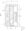
- FIG. 3 is a diagram illustrating an example of an image to be displayed on the display unit of the display device according to the first embodiment and a plurality of divided regions formed in the image.
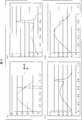
- FIG. (A)-(d) is a figure for demonstrating the concept of the method of specifying an empty area
- 6 is a flowchart illustrating an example of processing in the display device according to the first embodiment. 6 is a diagram illustrating an example of a configuration of a display device according to a modification of the first embodiment.
- FIG. 10 is a diagram illustrating an example of an image to be displayed on the display unit of the display device according to the second embodiment and a plurality of divided regions formed in the image.
- FIG. 6 is a diagram illustrating an example of a configuration of a display device according to a third embodiment.
- FIG. It is a figure which shows an example of the image used as the display object of the display part of the display apparatus which concerns on Embodiment 3, and the some area
- FIG. 10 is a diagram illustrating an example of a configuration of a display device according to a fourth embodiment. It is a figure which shows an example of the image used as the display target of the display part of the display apparatus which concerns on Embodiment 4, and the several division area formed in the said image. It is a figure which shows an example of the post-process image displayed on the said display part. 14 is a flowchart illustrating an example of processing in the display device according to the fourth embodiment.
- FIG. 10 is a diagram for explaining an example of processing of a display device according to a fifth embodiment.
- FIG. 10 is a diagram for explaining an example of processing of a display device according to a fifth embodiment.
- Embodiment 1 Hereinafter, Embodiment 1 of the present disclosure will be described in detail based on FIGS. 1 to 5.
- a physical color can be defined by tristimulus values (X, Y, Z).
- the tristimulus values are obtained by integrating values calculated based on (luminance of light source) ⁇ (reflectance of object) ⁇ (human visual sensitivity) at each wavelength of about 400 nm to 800 nm. Since the color represented by these tristimulus values is an absolute color, colors that show the same stimulus value should look the same color. However, depending on the situation or environment, a human may feel a psychologically different color even if the colors show the same stimulus value.
- German psychologist David Katz classifies psychological colors based on the knowledge that the appearance of colors varies not only with tristimulus values but also with the localization or texture of the object (object).
- surface color refers to a color that can be perceived so that the localization or texture of the object surface cannot be clearly perceived, and that cannot be sensed with attributes other than the color attribute.
- a blue sky color sometimes referred to as “sky blue”.
- edges or textures are not stereotactic. That is, such an edge or texture changes its position or disappears every time a distant blue sky is reviewed, unlike a cloud, bird, airplane, or sunset sky that is clearly different from the blue sky. It is not a target that humans are clearly aware of.
- the edge or texture may be recognized as being obtained from an actually existing object. This is because the distance from the person to the display surface of the display device is much closer than the distance from the person to the distant blue sky, so that the position of the object is psychologically specified to be close to the person. Arise. As a result, in the above case, the distant blue sky may appear unnatural.
- the image processing apparatus performs a blurring process on the sky region based on the color of the sky region (eg, distant view and background). Specifically, when the color of the sky region is sky blue, the image processing apparatus performs edge processing or a texture in a region that can be recognized as a face color psychologically by performing a blurring process on the sky region. Eliminate. Thereby, a surface color can be perceived as a surface color, and a natural way of viewing the sky region can be provided.
- the color of the sky region eg, distant view and background.
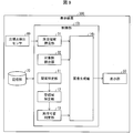
- FIG. 1 is a diagram illustrating an example of the configuration of the display device 100.
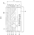
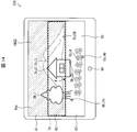
- FIG. 2 is a diagram illustrating an example of an image IMG1 (display target image) to be displayed on the display unit 50 (display surface) and a plurality of divided regions A1 to A3 formed in the image IMG1.
- FIGS. 3A to 3D are diagrams for explaining the concept of a technique for identifying the sky region Bs using a graph expressing the relationship between the brightness and the number of pixels in each of the divided regions A1 to A3.
- FIG. FIG. 4 is a diagram illustrating an example of the processed image IMG2 displayed on the display unit 50.
- FIG. 2 shows an example in which an image IMG1 (input image) before processing by the control unit 10 is displayed on the display unit 50 for the sake of simplification, but actually, as described later, An image processed by the control unit 10 (for example, the processed image IMG2 shown in FIG. 4) is displayed on the display unit 50.
- This also applies to FIGS. 10, 17, and 20 to 22 after the second embodiment.
- the images IMG1 shown in these figures are the same.
- the display device 100 displays an image, and includes a control unit 10 (image processing device), a display unit 50, and a storage unit 70.
- the controller 10 will be described later.
- the display unit 50 displays an image under the control of the control unit 10, and is composed of, for example, a liquid crystal panel. In the present embodiment, the display unit 50 displays the processed image IMG2 (see FIG. 4).
- the storage unit 70 stores, for example, various control programs executed by the control unit 10, and is configured by a non-volatile storage device such as a hard disk or a flash memory.
- the storage unit 70 stores, for example, image data indicating the image IMG1.
- control unit 10 reads out image data indicating the image IMG1 as a still image stored from the storage unit 70.
- image data indicating the image IMG1 is stored in the storage unit 70, and the moving image data may be read by the control unit 10.
- the control unit 10 may perform image processing described below for each frame constituting the moving image.
- the image data or the moving image data is not necessarily stored in the storage unit 70 in advance, and may be acquired by receiving a broadcast wave, or may be acquired by receiving image data or a moving image connected to the display device 100. You may acquire from the external apparatus (for example, recording device) which stores or produces
- the external apparatus for example, recording device
- examples of the display device 100 include a personal information computer such as a PC (Personal Computer), a multi-function mobile phone (smart phone), a tablet, or a television.
- a personal information computer such as a PC (Personal Computer), a multi-function mobile phone (smart phone), a tablet, or a television.
- the control unit 10 controls the display device 100 in an integrated manner. Particularly in the present embodiment, the control unit 10 has an image processing function for performing a predetermined process on the image IMG1 shown in FIG. 2.
- the relationship specifying unit 11 determines the brightness of each of the plurality of pixels constituting the image IMG1 and the brightness. The relationship with the number of pixels having
- the relationship specifying unit 11 reads the image data stored in the storage unit 70, and specifies the vertical direction (Y-axis direction in FIG. 2) of the image IMG1 indicated by the image data. Then, as shown in FIG. 2, the image IMG1 is divided into a plurality of divided regions A1 to A3 in accordance with the vertical direction. That is, a plurality of divided areas A1 to A3 are formed (set) for the image IMG1.
- the width h (length in the vertical direction) of the plurality of divided regions A1 to A3 is set so as to divide the width (length) H in the Y-axis direction of the image IMG1 into approximately three equal parts. . That is, it is set as h ⁇ H / 3.
- the width H can be appropriately adjusted in accordance with effective execution of actual image processing.
- the lower part ( ⁇ Y axis direction) of the display unit 50 corresponds to the foreground (front side of the landscape), and the upper side (+ Y axis direction) corresponds to the distant view (of the landscape). Often corresponds to the back side. Therefore, by dividing the image IMG1 in the vertical direction of the image IMG1 to form a plurality of divided regions A1 to A3, the image generation unit 14 considers the perspective of the image (the three-dimensional depth of the landscape). Thus, it is possible to generate the processed image IMG2 that is close to the actual appearance in the natural world.
- the width and number of the plurality of divided areas can be arbitrarily set.
- the width of at least a part of the plurality of divided regions may be different from the width of other divided regions. Further, the number of the plurality of divided regions may be two, or may be four or more.
- the relationship specifying unit 11 Based on the gradation values (for example, three gradation values of a red gradation value, a green gradation value, and a blue gradation value) possessed by each of a plurality of pixels constituting the image IMG1, the relationship specifying unit 11 The brightness of the pixel is calculated, and the number of pixels having the brightness is counted. Then, the relationship specifying unit 11 specifies the relationship between the calculated brightness and the number of counted pixels for each of the divided regions A1 to A3. The relationship specifying unit 11 may express the relationship as a graph (brightness distribution) in which the horizontal axis represents lightness and the vertical axis represents appearance frequency (number of pixels), for example.
- a graph (brightness distribution) in which the horizontal axis represents lightness and the vertical axis represents appearance frequency (number of pixels), for example.
- the graph expressing the above relationship is, for example, a graph as shown in (b) to (d) of FIG.
- the relationship identifying unit 11 associates the identified relationship with each of the divided regions A1 to A3, and transmits the relationship to the empty region identifying unit 12 as specific relationship data.
- the relationship specifying unit 11 can also function as part of the image processing function. In this case, the process can be simplified.
- the empty area specifying unit 12 specifies an empty area Bs corresponding to the sky in the image IMG1.
- the sky region specifying unit 12 is configured such that the number of pixels indicated by the peak in the graph expressing the relationship for each of the plurality of divided regions A1 to A3 specified by the relationship specifying unit 11 is the divided region in the image IMG1.
- the area formed by the pixels corresponding to the peak is specified as the distant view area.
- the sky area specifying unit 12 determines that the distant view area is included in the image IMG1, and specifies the distant view area as the empty area Bs.
- the graphs shown in (a) to (d) of FIG. 3 are graphs showing the above-described relationships in a given display target image with the horizontal axis representing the brightness and the vertical axis representing the appearance frequency.
- the value on the vertical axis is given for convenience, and the value has no substantial meaning.
- the value on the horizontal axis is a value obtained by normalizing the brightness.
- an arbitrary display target image includes an area corresponding to the sky (empty area Bs in FIG. 2) and an object group other than the area. For ease of explanation, the area corresponding to the sky will be described as the empty area Bs in the description of FIG.
- the graph showing the above relationship in the empty region Bs tends to be narrow.
- the graph showing the above relationship in the sky region Bs is a narrow graph having a peak when the lightness value is around 0.8.
- the graph showing the relationship in the object group tends to be broad.
- the graph showing the above relationship in the object group is a broad graph having a peak when the value of brightness is around 0.5.
- the graph in the object group may have a plurality of peaks.
- a graph (a histogram of the display target image and a brightness distribution of the display target image) as shown in FIGS. 3B to 3D is obtained.
- the graphs showing the above relationships shown in (b) to (d) of FIG. 3 prepare three display target images having different ratios of the empty regions Bs, and each of the three display target images shown in (a) of FIG. This is a result of generating two graphs and synthesizing the two graphs.
- the ratio of the empty region Bs in the display target image decreases in the order of (b) to (d) in FIG.
- the number of pixels indicated by the peak of the graph showing the above relationship and pixels having brightness near the peak decreases as the ratio of the sky region Bs decreases. I understand that.
- the ratio of the distant view area to the display target image is larger on the upper side of the display target image than on the lower side. Accordingly, the transition of the number of pixels indicated by the peak as shown in (b) to (d) of FIG. 3 (which may include the number of pixels having brightness near the peak) is changed from the upper side of the display target image to the lower side.
- a distant view area in the display target image that is, whether or not the distant view area as the sky area Bs is included in the image IMG1.
- the sky region specifying unit 12 includes the number of pixels indicated by the peak in the graph expressing the above relationships of the divided regions A1 to A3 specified by the relationship specifying unit 11 (may include the number of pixels having brightness near the peak). Is identified. Then, when the number of the pixels in the divided regions A1 to A3 decreases in that order, the sky region specifying unit 12 specifies the region formed by the pixels having the lightness near the peak and the peak as the distant view region. Then, it is determined that the image IMG1 includes a distant view area as the sky area Bs. That is, the sky area specifying unit 12 specifies the pixels having the peak and the brightness near the peak as pixels constituting the distant view area.
- the sky region specifying unit 12 selects pixels having a lightness within a predetermined range (for example, a range of ⁇ 0.1 in lightness after normalization) from the lightness corresponding to the peak (maximum value of the number of pixels). , It is specified as a pixel constituting a distant view area.
- a predetermined range for example, a range of ⁇ 0.1 in lightness after normalization
- the sky region specifying unit 12 adds an empty region to the image IMG1 if at least one of the plurality of peaks decreases as described above. It is determined that Bs is included.
- the empty region specifying unit 12 transmits pixel data indicating pixels constituting the empty region Bs to the execution determination unit 13.
- the image IMG1 itself does not have information such as what the object included in the image IMG1 is and how large the object is. Therefore, in a general display device, the above information is acquired based on a database search or analysis of metadata accompanying the image IMG1.
- the display device 100 only needs to be able to specify the empty region Bs as the target of the blurring process.
- the display device 100 can specify the distant view area on the assumption that the distant view area is the sky area Bs. Therefore, in the display device 100, the sky region specifying unit 12 can specify the distant view region by a simple method that only uses the relationship specified by the relationship specifying unit 11 (a graph expressing the relationship). That is, the perspective determination in the image IMG1 can be performed by a simple method. The same can be said for the processing of Modification 1 of the present embodiment described later.
- the executability determination unit 13 determines whether or not to perform the blurring process on the sky region Bs based on the color of the sky region Bs specified by the sky region specifying unit 12.
- the feasibility determination unit 13 includes a specific color in the color of the pixel specified by the sky region specifying unit 12 and the number of pixels having the specific color in the distant view region is a predetermined number or more. In this case, it is determined that the blurring process is performed on the sky region Bs.
- the specific color refers to a color in which the color of the sky region Bs can be determined as a surface color, such as a color of the sky region Bs of blue sky (referred to as sky blue in the present embodiment).
- the predetermined number refers to the number of pixels that can be determined that the sky region Bs has a sky spread. In other words, when the pixel of the sky region Bs having a size that can be defined as sky indicates a sky blue color, the feasibility determination unit 13 determines that the sky region Bs is a surface color and blurs the sky region Bs. Is determined to be performed.
- the execution determination unit 13 determines whether or not the color is sky blue using, for example, a 24-color ring of PCCS (Practical Color Co-ordinate System).
- PCCS Practical Color Co-ordinate System
- the executability determination unit 13 determines that the color of the pixel is a sky blue.
- the specific color is 15: BG, 16: gB or 17: B.
- the specific color is not limited to the above, and a color that can determine the color of the sky region Bs as the surface color may be selected as the specific color. Further, there is no need to set a specific color using the 24-color circle of PCCS, and for example, a specific color may be selected from a hue group divided into 6, 12, or 20 types.
- the execution determination unit 13 also includes an empty area Bs1 included in the divided area A1 (upper divided area) among the divided areas A1 to A3, and a divided area A2 (lower divided area) adjacent to the divided area A1. ) Included in the empty area Bs2 included in the divided area A1 may be subject to blurring processing. That is, in this case, even if it is determined that the blurring process is once performed on the sky area Bs2, the execution possibility determination unit 13 determines that the blurring process is not performed on the sky area Bs2.
- the sky region Bs is composed of sky regions Bs1 and Bs2.
- the execution determination unit 13 determines whether or not the empty region Bs is continuous at the boundary between the divided region A1 and the divided region A2 in the image IMG1.
- the executability determination unit 13 specifies pixels near the boundary in the empty region Bs1 included in the divided region A1, and specifies pixels near the boundary in the empty region Bs2 included in the divided region A2.
- the feasibility determination unit 13 identifies an area where these pixels are adjacent at the boundary as a contact area, and the number of adjacent pixels within the contact area is greater than or equal to a predetermined number, or all of the pixels near the boundary. It is determined whether or not there is a predetermined ratio or more with respect to the number.
- the feasibility determination unit 13 determines that the empty region Bs2 is continuous with the empty region Bs1, and blurs the empty region Bs2 as well. Target of processing.
- the number is less than the predetermined number or the predetermined ratio
- the dotted framed area is an area specified as the contact area.
- the sky region Bs may actually be an object different from the sky. In this case, since the target object can clearly visually recognize the actual state, it is not appropriate to perform the blurring process on the target object.
- the upper side of the image IMG1 is often a distant view area. Therefore, by determining whether or not the empty area Bs is continuous from the upper (upper) divided area toward the lower (lower) divided area, the empty area Bs2 included in the lower divided area is also determined. It can be determined whether or not the sky region Bs1 indicates sky. In other words, if it is determined that it is not continuous, it can be determined that the sky region Bs2 actually indicates an object other than the sky, and the blur processing is not performed on the object. be able to. As a result, it is possible to prevent the above-described inappropriate blurring process from being performed.
- the predetermined amount may be set to a value that can be determined to be the continuous.
- the predetermined amount can be set to 20%, for example.
- the number of pixel pairs in which the upper and lower pixels across the boundary are both sky blue is 20% of the display horizontal pixel number (the total number of pixels aligned in the horizontal direction (X-axis direction) of the image IMG1).
- the empty regions Bs1 and Bs2 are continuous.
- the upper divided area is the divided area A1, and the lower divided area is the divided area A2.
- the upper divided area is the divided area A2, and the lower divided area is the divided area A3. The same can be explained.
- the execution availability determination unit 13 transmits to the image generation unit 14 the determination result as to whether or not to perform the blurring process on the sky region Bs.
- the image generation unit 14 generates the post-processing image IMG2 by performing the blurring process on the sky region Bs when the execution determination unit 13 determines to perform the blurring process. That is, the image generation unit 14 performs a process of generating the post-processing image IMG2 illustrated in FIG. Then, the image generation unit 14 displays the processed image IMG2 on the display unit 50 by transmitting image data indicating the generated processed image IMG2 to the display unit 50.
- the blurring process is realized by a known method using, for example, a filter (for example, a low-pass filter).
- a filter for example, a low-pass filter
- the process which applies the low-pass filter comprised from a 3x3 matrix (average matrix) is mentioned.
- a 3 ⁇ 3 matrix may have a central value of 0 and a value of 1/8 in other regions, or a central value of 1/2 and a value of 1/16 in other regions.
- the present invention is not limited to this, and various low-pass filters including a simple average matrix can be applied to the blurring process. That is, it is only necessary that the blurring process is performed to such an extent that a clear edge and texture cannot be visually recognized in the sky region Bs when the display device 100 displays the processed image IMG2.
- the matrix size of the low-pass filter may be selected appropriately in consideration of the application of the display device 100, the circuit scale of the display device 100, or the resolution of the display unit 50.
- the matrix size is about 5 ⁇ 5 to 15 ⁇ 15. It may be the size of According to the study by the present inventors, by applying a low-pass filter of about 5 ⁇ 5 for high vision, about 9 ⁇ 9 for 4K, and about 13 ⁇ 13 for 8K, the sky region Bs is applied. Has been confirmed to approach the actual appearance (natural appearance).
- the application of the low-pass filter in the present embodiment is not for noise removal in the sky region Bs but for clearly blurring (blurring) the sky region Bs.
- blurring can be performed with a 3 ⁇ 3 low-pass filter, it is preferable to apply a low-pass filter having a size larger than 3 ⁇ 3 as described above in order to achieve the purpose of blurring more clearly. .
- the image generation unit 14 performs blurring processing on the entire sky region Bs.
- the edge of the object may also be blurred.
- the object actually observed in the sky can be clearly seen because it has both edges and texture, but its position (feeling of distance) is familiar with the sky (background) and its clarity is Decrease.
- By blurring the edges of the object as described above it is possible to approximate the appearance of the actual object in the processed image IMG2.
- the present inventors have confirmed that when the edge of the object is emphasized, the object appears to be raised from the display surface, and the natural appearance of the sky is impaired.
- the post-processing image IMG2 generated by the image generation unit 14 from the image IMG1 shown in FIG. 2 is as shown in FIG. Note that the color of the sky region Bs in FIG. 2 is sky blue in most of the regions, and the contact region of the sky region Bs in the divided regions A1 and A2 is a predetermined amount or more.
- the blurring process is performed on the empty area Bs. Also, blurring processing is performed on (i) the edge between the sky region Bs and the object Obj1 (tree), and (ii) the edge between the sky region Bs and the object Obj3 (mountain).
- the region other than the above (i) and (ii) (including a part of the objects Obj1 and Obj3, the object Obj2 (house), and the object Obj4 (flower)) remains the image IMG1. That is, the image IMG1 is subjected to a blurring process so that the edge and texture cannot be visually recognized in the area determined to be the face color, and the edge and texture are held for the area determined not to be the face color. Further, the textures are held inside the objects Obj1 and Obj3.
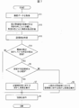
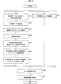
- FIG. 5 is a flowchart illustrating an example of processing in the display device 100.
- the relationship specifying unit 11 reads image data from the storage unit 70 (S1), and divides the image IMG1 into a plurality of divided regions A1 to A3 in accordance with the vertical direction of the image IMG1.
- the relationship specifying unit 11 specifies the relationship in each of the divided areas A1 to A3 (S2).
- the number of pixels indicating the peak of the graph expressing the above relationship in each of the divided regions A1 to A3 specified by the relationship specifying unit 11 decreases from the divided region A1 toward the divided region A3.
- an area formed by the pixels corresponding to the peak is specified as a distant view area.
- the sky region specifying unit 12 determines that the distant view region is included in the image IMG1, and specifies the distant view region as the sky region Bs (S3; sky region specifying step).
- the sky region specifying unit 12 specifies the pixel corresponding to the peak as a pixel constituting the sky region Bs (S4), and determines whether or not the pixel is sky blue and exists in a predetermined number or more (S5). ; Executability determination step).
- the execution determination unit 13 determines whether or not the empty areas Bs in the divided areas A1 and A2 are continuous (S6; execution determination process). Specifically, the feasibility determination unit 13 determines whether or not the contact areas in the divided areas A1 and A2 exist in a predetermined amount or more. On the other hand, if NO in S5, the image generation unit 14 displays the image IMG1 on the display unit 50 without performing the blurring process on the image IMG1 (S8).
- the feasibility determination unit 13 determines to perform the blurring process on the entire empty area Bs.
- the image generation unit 14 generates a processed image IMG2 by performing blurring processing on the entire sky region Bs (S7; image generation step).
- the image generation unit 14 displays the processed image IMG2 on the display unit 50 (S8).
- the feasibility determination unit 13 determines that the blurring process is performed only on the empty area Bs1 included in the divided area A1 in the empty area Bs.
- the image generation unit 14 performs the blurring process only on the sky region Bs1, and generates a processed image IMG2 (an image different from the processed image IMG2 illustrated in the example of FIG. 4) (S9). Image generation step).
- the image generation unit 14 displays the processed image IMG2 on the display unit 50 (S8).
- FIG. 6 is a diagram illustrating an example of the configuration of the display device 100a.
- the display device 100a includes a control unit 10a (image processing device) that comprehensively controls the display device 100a.
- the control unit 10a has an image processing function for performing predetermined processing on the image IMG1 shown in FIG. 2, and includes a pixel counting unit 21, a sky region specifying unit 12a, an execution availability determination unit 13a, and an image generation unit 14. Is provided. That is, the control unit 10 a is different from the control unit 10 mainly in that a pixel counting unit 21 is provided instead of the relationship specifying unit 11. This means that the method of specifying the empty area Bs is different from the method of the control unit 10.
- the pixel counting unit 21 classifies each of the plurality of pixels constituting the image IMG1 into one of a plurality of predetermined colors for each of the divided regions A1 to A3.
- the plurality of predetermined colors for example, 24 colors in the 24-color ring of PCCS can be used.
- the plurality of predetermined colors is not limited to 24 colors.
- the pixel counting unit 21 reads the image data stored in the storage unit 70 and, like the relationship specifying unit 11, the image IMG1 is divided into a plurality of divided regions A1 to A3 in accordance with the vertical direction as shown in FIG. To divide. In addition, the pixel counting unit 21 calculates the color of each pixel based on the gradation value that each of the plurality of pixels constituting the image IMG1 has. The pixel counting unit 21 classifies the calculated color of each pixel into one of a plurality of predetermined colors for each of the divided regions A1 to A3. The pixel counting unit 21 counts the number of classified pixels (appearance frequency) for each predetermined color. The pixel counting unit 21 transmits pixel number data indicating the number of pixels associated with each predetermined color to the sky region specifying unit 12a.
- the empty area specifying unit 12a specifies the empty area Bs in the image IMG1 similarly to the empty area specifying unit 12.
- the sky area specifying unit 12a moves from the divided area A1 (the divided area located on the upper side) to the divided area A3 (the divided area located on the lower side) for any one of the predetermined colors.
- an area formed by the pixels having the reduced number is specified as a distant view area.
- the sky area specifying unit 12a determines that the image IMG1 includes a distant view area as the sky area Bs.
- the sky area specifying unit 12a determines that the image IMG1 includes the sky area Bs, the sky area specifying unit 12a indicates a predetermined color in which the number of pixels is reduced (a predetermined color corresponding to the pixels constituting the distant view area). The color data is transmitted to the execution determination unit 13a.
- the execution availability determination unit 13a determines whether to perform the blurring process on the sky region Bs based on the color of the sky region Bs.
- the feasibility determination unit 13a identifies that the pixel indicating the predetermined color constitutes the sky region Bs, and It is determined that the blurring process is performed on the sky region Bs including the pixel. Whether or not the predetermined color is sky blue is determined based on whether or not the predetermined color is, for example, 15: BG, 16: gB, or 17: B in the 24-color circle, as described above. Then, the feasibility determination unit 13a transmits to the image generation unit 14 a determination result as to whether or not to perform the blurring process on the sky region Bs.
- the color indicating the color of the empty area Bs (location that can be the target of the determination process) and the coefficient thereof necessary for the determination process of the execution determination unit 13a is already evaluated in the empty area specifying unit 12a. It can be said that. Therefore, the feasibility determining unit 13a can determine the sky region Bs indicating the sky color that can be specified by the sky region specifying unit 12a as the executable region of the blurring process.
- the color of the pixel is evaluated in specifying the sky region Bs. Therefore, unlike the display device 100, it is not necessary to perform a two-step step of evaluating the color of the pixels in the sky region Bs after specifying the sky region Bs based on the above relationship. Therefore, the display device 100a can perform processing more easily than the display device 100.
- FIG. 7 is a flowchart illustrating an example of processing in the display device 100a.
- the pixel counting unit 21 reads image data from the storage unit 70 (S11), and divides the image IMG1 into a plurality of divided regions A1 to A3.
- the pixel counting unit 21 classifies the calculated color of each pixel into one of a plurality of predetermined colors for each of the divided areas A1 to A3, and counts the number of pixels for each predetermined color (S12).
- the sky area specifying unit 12a is formed by pixels having a reduced number when the number of pixels decreases from the divided area A1 toward the divided area A3 in any of a plurality of predetermined colors.
- the area is specified as a distant view area. That is, the sky area specifying unit 12a determines that the image IMG1 includes a distant view area, and specifies the distant view area as the empty area Bs (S13; sky area specifying step).
- the execution determination unit 13a determines whether or not the predetermined color in which the number of pixels is decreasing is a sky blue (S14; execution determination step). If YES in S14, the process proceeds to S6. On the other hand, in the case of NO in S14, the image generation unit 14 displays the image IMG1 on the display unit 50 without performing the blurring process on the image IMG1 (S8).
- the control unit 10 or 10a When the number of pixels indicated by the peak of the graph expressing the above relationship or the number of pixels of a predetermined color is reduced in each of the divided regions A1 to A3, the control unit 10 or 10a is a region including the pixel. Is specified as a distant view area, but is not limited thereto. For example, the controller 10 or 10a tends to decrease the number of pixels as a whole in the divided regions A1 to A3, but even if there is a portion where the number of pixels is constant in some of the pixels, You may identify the area
- the area including the pixel is defined as a distant view area.
- the divided areas A1 and A2 are constant and the number of pixels in the divided areas A2 and A3 is reduced, the divided areas A2 and A3 correspond to the set of divided areas.
- the empty area Bs of the divided areas can be the target of the blurring process.
- the divided areas are set finely as in the second embodiment, it can be assumed that the number of pixels in the adjacent divided areas can be constant, but even in such a case, the distant view area can be accurately identified. It becomes possible.
- the blurring process can be performed on the sky region Bs even when the entire image IMG1 is a blue sky.
- the control unit 10 or 10a may detect an edge in the image IMG1. In this case, the control unit 10 or 10a detects the edge after acquiring the image data from the storage unit 70. Thereby, the objects Obj1 to Obj4 (for example, the contours of the objects Obj1 to Obj4) in the image IMG1 are detected.
- the texture of the objects Obj1 and Obj3 having the boundary with the sky region Bs may be reduced, or the objects Obj1 and Obj3
- the edges may become sharper.
- the sky region Bs can be blurred, and only the edge of the objects Obj1 and Obj3 or the vicinity of the edge can be surely blurred. Therefore, the above possibility can be reduced.
- edge detection is not essential. That is, as described above, it is not always necessary to detect the objects Obj1 to Obj4 by detecting the edge.
- control unit 10 or 10a combines the image obtained by performing the blurring process on the sky region Bs and the image obtained by performing another image processing on the image IMG1, thereby obtaining the processed image IMG2. It may be generated. However, when different processing is performed on the pixels constituting the two images, the blurring processing for the sky region Bs is preferentially applied.
- Examples of the other image processing include enhancement processing or blurring processing performed according to a predetermined condition.
- An example of performing enhancement processing or blurring processing according to such a predetermined condition will be described in the third and subsequent embodiments.
- the display device 100 has been described as including the control unit 10 and the display unit 50.
- the display device 100 is not limited thereto, and, for example, an external device (image) that can be communicably connected to the display device having the display unit 50.
- the processing apparatus may have the image processing function of the control unit 10. The same applies to the display device 100a.
- the display device 100 or 100a determines whether or not to perform the blurring process based on the color of the sky area Bs, and performs the blurring process on the sky area Bs when it is determined to perform the blurring process.
- the color of the sky region Bs to be subjected to the blurring process is a color that can be recognized as a surface color (for example, blue sky). For this reason, with respect to the sky region Bs recognized as the surface color, the visibility as the surface color can be improved by removing the edge or texture, and can be brought close to the actual sky appearance in the natural world.
- FIG. 8 is a diagram illustrating an example of the image IMG1 to be displayed on the display unit 50 and a plurality of divided regions B1 to B6 formed in the image IMG1.
- the width h of the plurality of divided regions A1 to A3 is set so that the width H of the image IMG1 is approximately equal to three.
- the divided regions B1 to B4 have different widths.
- the divided regions B1 to B4 (upper side) are larger than the width hb (length in the vertical direction) of the divided regions B5 and B6 (lower divided regions).
- the width ha (the length in the vertical direction) of the divided region) is shorter.
- the divided areas B1 to B4 are set as upper half areas in the image IMG1, and the divided areas B5 and B6 are set as lower half areas in the image IMG1.
- the width ha of the divided areas B1 to B4 is set to 1/8 of the width H of the image IMG1
- the width hb of the divided areas B5 and B6 is set to 1/4 of the width H. ing.
- the empty area Bs can be specified more accurately by setting the width ha of the divided areas B1 to B4 positioned above the width hb of the divided areas B5 and B6 positioned on the lower side. It becomes.
- the setting method of the divided areas B1 to B6 is not limited to the above, and for example, the widths ha and hb of the plurality of divided areas B1 to B6 may be set so as to increase in order (stepwise) downward. Good.
- the width ha of at least one of the divided areas B2 to B4 (for example, divided area B4) constituting the upper divided area is equal to the width hb of the divided areas B5 and B6 constituting the lower divided area. It may be the same length. That is, the width ha of at least one of the divided areas constituting the upper divided areas B1 to B4 is set shorter than the width hb of at least one divided area constituting the lower divided areas B5 and B6. It only has to be.
- the display device 200 can perform the processing of the display device 100 or 100a of the first embodiment, and in that case, the effect of the display device 100 or 100a can be achieved. This also applies to the display devices 300 to 500 in the third and later embodiments described below.
- the display device 300 In the first embodiment, the process in the case of performing the blurring process on the sky area Bs based on the color of the sky area Bs has been described.
- the display device 300 according to the third embodiment generates the processed image IMG2 by performing the enhancement process or the blurring process in consideration of the position where the viewer 90 looks at the display unit 50 in addition to the process. To do.
- FIG. 9 is a diagram illustrating an example of the configuration of the display device 300.
- FIG. 10 is a diagram illustrating an example of the image IMG1 to be displayed on the display unit 50 and a plurality of divided regions A1 to A3 formed in the image IMG1.
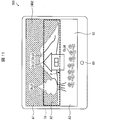
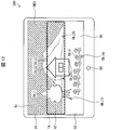
- 11 to 14 are diagrams illustrating an example of the processed image IMG2 displayed on the display unit 50.
- FIG. 10 is a diagram illustrating an example of the image IMG1 to be displayed on the display unit 50 and a plurality of divided regions A1 to A3 formed in the image IMG1.
- 11 to 14 are diagrams illustrating an example of the processed image IMG2 displayed on the display unit 50.
- the display device 300 displays an image, and includes a control unit 10 b (image processing device), a display unit 50, a gazing point detection sensor 60 (sensor), and a storage unit 70. .
- the gazing point detection sensor 60 detects the gazing point F of the viewer 90 on the display unit 50, and transmits gazing point data indicating the detected gazing point F to the control unit 10b.
- the gazing point detection sensor 60 is realized by, for example, an eye tracker that detects the movement of the line of sight of the viewer 90 by detecting the movement of the eyeball of the viewer 90. Further, the position of the gazing point F is represented by, for example, xy coordinates arbitrarily set on the display unit 50.
- the control unit 10b controls the display device 300 in an integrated manner.
- the control unit 10b has an image processing function for performing a predetermined process on the image IMG1 illustrated in FIG. 10.
- the image generating unit 14b, the attention area specifying unit 31, and the object detecting unit 32 are provided. That is, the control unit 10b is different from the control unit 10 in that the control unit 10b includes an image generation unit 14b, an attention area specifying unit 31, and an object detection unit 32.
- this embodiment demonstrates as what the control part 10b is equipped with the structure of the control part 10, it can replace with the said structure and can also be equipped with the structure of the control part 10a.
- the processing of the attention area specifying unit 31 and the object detection unit 32 is performed when there is only one viewer. In other words, when the display device 300 determines that a plurality of viewers 90 are looking at the display unit 50 by the face detection function for detecting the face of the viewer 90, the attention area specifying unit 31 and the object detection unit 32. Do not perform the process. The same applies to the fourth and fifth embodiments.
- the attention area specifying unit 31 specifies the attention area TA, which is the divided area that the viewer 90 is paying attention to, among the divided areas A1 to A3, based on the gazing point F detected by the gazing point detection sensor 60. That is, the attention area specifying unit 31 specifies the attention area TA in the divided areas A1 to A3 and also specifies the non- attention area (the divided area other than the attention area TA).
- the attention area specifying unit 31 reads the image data stored in the storage unit 70, specifies the up-down direction of the image IMG1 indicated by the image data, and matches the up-down direction.
- the image IMG1 is divided into divided areas A1 to A3.
- the attention area specifying unit 31 determines which of the position coordinates indicating the divided areas A1 to A3 the gazing point (position coordinates) F indicated by the gazing point data acquired from the gazing point detection sensor 60 matches. That is, the attention area specifying unit 31 specifies which of the divided areas A1 to A3 the gazing point F is included in. Then, the attention area specifying unit 31 specifies the divided area including the gazing point F as the attention area TA. In the example of FIG. 10, the divided area A2 is specified as the attention area TA. Further, the divided areas A1 and A3 are specified as non-target areas.
- the attention area identification unit 31 transmits area identification data indicating the correspondence between the divided areas A1 to A3, the attention area TA, and the non-attention area to the object detection unit 32.
- the object detection unit 32 detects the objects Obj1 to Obj4 in the image IMG1. Specifically, the object detection unit 32 reads the image data stored in the storage unit 70 and detects the objects Obj1 to Obj4 by detecting edges (edge regions) in the image IMG1 indicated by the image data. To do.
- the object detection unit 32 uses, for example, a filter to detect, as an edge, a region in which the difference in pixel value between adjacent pixels is equal to or greater than a predetermined value (that is, a region where the brightness is rapidly changed).
- a predetermined value that is, a region where the brightness is rapidly changed.
- a closed region formed by (or a region considered to be closed) is detected as an object.
- detection is not limited to pixel value differences, and for example, an area where the difference in values indicating the hue is a predetermined value or more (that is, an area where the color changes rapidly) may be detected as an edge.
- edge processing based on the depth information may be performed.
- the object detection unit 32 detects whether the detected objects Obj1 to Obj4 exist in the attention area TA or the non-attention area indicated by the area specifying data, and the detection result is displayed as an image generation section. 14b.
- the object detection unit having a function of detecting that the objects Obj1 to Obj4 are present in the attention area TA may be referred to as a first object detection unit.
- the object detection unit having a function of detecting that the objects Obj1 to Obj4 are present in the non-attention area may be referred to as a second object detection unit.
- the object detection unit 32 will be described as having both functions of the first and second object detection units. However, each of the first and second object detection units may be provided as an individual functional unit.
- the object Obj1 is included in the divided area A2 which is the attention area TA, and is also included in the divided areas A1 and A3 which are non-attention areas.
- the object Obj2 is included in the divided area A2 that is the attention area TA and is also included in the divided area A3 that is the non-attention area.
- the object Obj3 is included in the divided area A2 that is the attention area TA and is also included in the divided area A1 that is the non-attention area.
- the object Obj4 is included only in the divided area A3 that is a non-target area.
- the object detection unit 32 gives a detection result indicating that the objects Obj1 to Obj3 are included in the attention area TA (divided area A2) and only the non-attention area (divided area A3) for the object Obj4.
- the detection result indicating that it is included is transmitted to the image generation unit 14b.
- the object detection unit 32 transmits coordinate data indicating the position coordinates of the objects Obj1 to Obj4 in the image IMG1 to the image generation unit 14b together with the detection result.
- the target object is included in both the attention area TA and the non-target area (target objects Obj1 to Obj3 shown in FIG. 10), they are included in both of them (the divided area A2 and the divided area A1). And / or A3) may be transmitted.
- the image generation unit 14b performs the same process as the image generation unit 14 (hereinafter also referred to as process P1). That is, when the execution determination unit 13 determines that the blur processing is performed on the sky region Bs, the image generation unit 14b performs the blur processing on the sky region Bs, thereby obtaining an image (hereinafter referred to as an image). IA). On the other hand, if it is determined not to perform the blurring process, the image IMG1 is generated as the image IA. In addition, the image generation unit 14b performs an enhancement process on the image IMG1 in at least a part of the attention area TA specified by the attention area specification unit 31 among the divided areas A1 to A3, and the non-target area.
- An image (hereinafter also referred to as image IB) is generated (hereinafter also referred to as process P2) by performing blurring processing at least in part.
- This enhancement processing is realized by a known method using, for example, a filter (edge enhancement filter).
- the image generation unit 14b generates the processed image IMG2 by combining the images IA and IB generated by the processes P1 and P2.
- the image generation unit 14b applies the result of the process to the post-processing image IMG2.
- the image generation unit 14b performs enhancement processing on at least a part of the non-processing area other than the sky area Bs in which the blurring process is performed in the attention area TA.
- the image generation unit 14b sequentially determines whether or not the color indicated by the pixel is sky blue for each of the plurality of pixels of the image IMG1. As this determination process, for example, the determination process in the execution determination unit 13 described in the first embodiment can be applied. Then, the pixel data indicating the corresponding pixel in the image IA is output for the pixel determined to be sky blue, and the pixel data indicating the corresponding pixel in the image IB is output for the pixel determined not to be sky blue, respectively. IMG2 is generated.
- the post-processing image IMG2 may be generated as follows.
- the image generation unit 14b When the image generation unit 14b generates the image IA by performing the blurring process on the sky region Bs, the position of the sky region Bs in the image IMG1 is naturally specified. Therefore, the image generation unit 14b generates a processed image IMG2 by generating a mask image in which the sky region Bs or other than the sky region Bs is masked, and performing a logical operation using the mask image, the image IA, and the image IB. To do.
- a reduced image may be used as the mask image. This is because the processing of the image generation unit 14b is a blurring process for the sky region Bs, so that a block-shaped adverse effect is hardly generated in the processed image IMG2. For example, when a 9 ⁇ 9 low-pass filter is used for the blurring process, it is possible to use a mask image having a size 1/8 of the image IMG1. When a reduced image is used as a mask image, interpolation processing using an intra-block address may be performed between the mask image and the images IA and IB.
- the image generation unit 14b generates the post-processing image IMG2 shown in FIGS. 11 to 14, for example, by performing the above-described processing.
- the post-processing image IMG2 shown in FIG. 11 reflects the image IA generated as a result of the following processing P1. That is, the execution possibility determination unit 13 determines that the sky region Bs is the target of the blurring process, and the image generation unit 14b performs the blurring process on the sky region Bs. With this blurring process, the blurring process is also performed on the edge between the sky region Bs and the object Obj1 and the edge between the sky region Bs and the object Obj3.
- processed image IMG2 shown in FIG. 11 reflects the image IB generated as a result of the following process P2.
- the image generation unit 14b performs an enhancement process on an object having at least a part in the attention area TA based on the detection result acquired from the object detection unit 32, and Then, the blurring process is performed on the object existing only in the non-attention area (processing PA).
- the image generation unit 14b specifies the positions of the objects Obj1 to Obj3 in the image IMG1 using the coordinate data, and performs an enhancement process on the objects Obj1 to Obj3. That is, the edges of the objects Obj1 to Obj3 are emphasized. In addition, even when the entire target object is included in the attention area TA, the image generation unit 14b performs enhancement processing on the target object.
- the image generation unit 14b specifies the position of the object Obj4 in the image IMG1 using the coordinate data, and performs a blurring process on the object Obj4. That is, the edge of the object Obj4 is blurred.
- the object Obj1 exists over all the divided areas A1 to A3. Therefore, the enhancement process is performed on the object Obj1 regardless of whether the attention area TA is the divided area A1 or A3. Since the object Obj2 exists across the divided areas A2 and A3, the object Obj2 is subjected to enhancement processing when the attention area TA is either the divided area A2 or A3, and the divided area A1. In the case of, a blurring process is performed. Since the object Obj3 exists across the divided areas A1 and A2, the object Obj3 is subjected to enhancement processing when the attention area TA is either the divided area A1 or A2, and the object Obj3 is the divided area A3. The blurring process is performed.
- the object Obj4 exists only in the divided area A3, the object Obj4 is subjected to enhancement processing when the attention area TA is the divided area A3, and is subjected to blurring processing when the attention area TA is the divided areas A1 and A2. .
- the image generation unit 14b combines the images IA and IB generated by the above processing so that the sky region Bs subjected to the blurring processing of the image IA is preferentially applied, thereby performing the post-processing shown in FIG.
- An image IMG2 is generated.
- the process P2 PA
- all the edges of the objects Obj1 to Obj3 are emphasized.
- the edges (i) and (ii) that have been subjected to the blurring process in the process P1 are described. It is blurred.
- the image generation unit 14b performs enhancement processing only on the part included in the non-processing area.
- most of the divided area A1 is the empty area Bs. Therefore, even if there is a gazing point F in the divided area A1, the sky area Bs subjected to the blurring process of the image IA is preferentially applied, and thus the edge of the object Obj3 included in the divided area A1 is blurred. Become.
- the post-processing image IMG2 illustrated in FIG. 12 reflects the image IA generated as a result of the same processing P1 as in FIG.
- processed image IMG2 shown in FIG. 12 reflects an image IB generated as a result of the following process P2.
- the image generation unit 14b performs processing P2 on an object having at least a part in the attention area TA based on the position of the lowermost ends Obj1b to Obj4b (lower ends) of the objects Obj1 to Obj4 in the image IMG1. It is then determined whether or not to perform enhancement processing (processing PB).
- the image generation unit 14b determines whether or not each of the objects Obj1 to Obj4 is included only in the attention area TA or the non-attention area using the detection result. If the image generation unit 14b determines that the entire object is included in the attention area TA, the image generation unit 14b performs enhancement processing on the object. In addition, when the image generation unit 14b determines that the entire object is included only in the non-attention area, the image generation unit 14b performs a blurring process on the object.
- the image generation unit 14b determines that the entire objects Obj1 to Obj4 are not included in the attention area TA (that is, the object exists across the attention area TA and the non-attention area). In this case, the position coordinates of the lowest ends Obj1b to Obj4b in the image IMG1 of the objects Obj1 to Obj4 are specified using the coordinate data. Then, the image generation unit 14b determines whether or not the position coordinates are included in the divided area that exists at the lower end of the attention area TA.
- the image generation unit 14b determines that the position coordinates are included in the divided region existing at the lower end of the attention region TA.
- the image generation unit 14b determines that the enhancement process is performed on the target object.
- the image generation unit 14b determines that the position coordinates are not included in the divided area existing at the lower end of the attention area TA (that is, the lowermost end of the target exists in the attention area TA).
- the object is determined to be blurred.
- the image generation unit 14b determines to perform the blurring process on the object Obj4.
- the image generation unit 14b determines whether or not the lowermost end Obj1b to Obj3b is included in the divided area A3 at the lower end than the attention area TA.
- the bottom end Obj1b of the object Obj1 and the bottom end Obj2b of the object Obj2 are each included in the divided area A3. For this reason, the image generation unit 14b determines that the enhancement processing is performed on the objects Obj1 and Obj2. On the other hand, the lowermost end Obj3b of the object Obj3 is not included in the divided area A3 (included in the attention area TA). For this reason, the image generation unit 14b determines to perform the blurring process on the object Obj3.
- the image generation unit 14b determines that the viewer 90 is paying attention to the objects Obj1 and Obj2 that mainly exist in the vicinity thereof, and emphasizes the objects Obj1 and Obj2. Processing is performed, and blurring processing is performed on the other objects Obj3 and Obj4. Therefore, even if the viewer 90 looks at the object Obj3 (around the mountainside) in the attention area TA, if the attention area TA is the divided area A2, it is determined that the object Obj3 is not being watched, and the object Blur processing is performed on Obj3.
- the image generation unit 14b generates the processed image IMG2 shown in FIG. 12 by combining the images IA and IB.
- the post-processing image IMG2 shown in FIG. 12 all edges of the objects Obj1 and Obj2 are emphasized in the process P2 (PB), but the object Obj1 is reflected in the non-processing area by reflecting the process P1. Only some of the included edges are highlighted.
- the image generation unit 14b determines whether or not to perform enhancement processing on the objects Obj1 to Obj4 having at least a part in the non-processing area based on the position of the lowest end Obj1b to Obj4b. . Then, based on the determination result, the image generation unit 14b performs enhancement processing on only a portion of the target object included in the non-processing region (a part of the target object Obj1 and the entire target object Obj2 in the example of FIG. 12). I do.
- the post-processing image IMG2 is subjected to enhancement or blurring processing as shown in FIG.
- the processing PB is performed, the post-processing image IMG2 is subjected to enhancement or blurring processing as shown in FIG.
- FIG. 15 is a flowchart illustrating an example of processing in the display device 300.
- SA sky region blur determination process
- FIG. 15 refers to S1 to S7 and S9 in FIG. 5, and as a result, an image IA is generated.
- the image IA may be generated by the processing of S11 to S14, S6, S7, and S9 shown in FIG.
- the attention area specifying unit 31 divides the image IMG1 into divided areas A1 to A3. Then, the attention area specifying unit 31 specifies the attention area TA from the divided areas A1 to A3 based on the gazing point data indicating the gazing point F detected by the gazing point detection sensor 60 (S21).
- the object detection unit 32 reads the image data from the storage unit 70 (S22), and detects an edge in the image IMG1 indicated by the image data (S23). Then, the object detection unit 32 detects the objects Obj1 to Obj4 included in the image IMG1 using the detected edge (S24), and the objects Obj1 to Obj4 are either the attention area TA or the non-attention area. It is detected (determined) whether it exists in the area (S25).
- the image generation unit 14b generates an image IB based on the detection result of the object detection unit 32. Specifically, the image generation unit 14b performs enhancement processing on the image IMG1 in at least a part of the attention area TA (S26), and performs blurring processing on at least a part of the non-attention area (S27). Specifically, the processing PA or PB is performed in S26 and S27, and as a result, the image IB is generated.
- the image generation unit 14b generates the processed image IMG2 by combining the image IA generated by the sky region blur determination process (SA) and the image IB generated by the processes of S21 to S27 (S28; Image generation step). Then, the image generation unit 14b displays the generated processed image IMG2 on the display unit 50 (S8).
- SA sky region blur determination process
- S28 image generation step
- processing of S21 and the processing of S22 to S24 may be performed in parallel, or the processing of S21 may be performed after the processing of S22 to S24.
- the processes of S26 and S27 may be performed in parallel, or the process of S26 may be performed after the process of S27.
- the processing of S21 to S27 may be performed after the processing of SA, or the processing of SA may be performed after the processing of S21 to S27.
- the display device 300 determines whether or not the blurring process can be performed on the sky region Bs, and performs the enhancement or blurring process based on the gazing point F in addition to the process P1 that performs the blurring process on the sky region Bs according to the determination result. P2 is performed. Therefore, the display device 300 can bring the sky region Bs closer to the actual appearance in the natural world, and the actual objects in the natural world can be obtained for the objects Obj1 to Obj4 without detecting the gaze point F with high accuracy. A three-dimensional appearance close to the appearance can be obtained.
- the image generation unit 14b is described as performing the enhancement process on at least a part of the attention area TA and the blurring process on at least a part of the non-attention area for the image IMG1 in the process P2. Not limited to this.
- the image generation unit 14b does not necessarily need to perform both the enhancement process and the blurring process in the process P2, and may be configured to perform only the enhancement process in at least a part of the attention area TA (non-processing area). That is, it is not always necessary to perform the blurring process on at least a part of the non-target area in the image generation unit 14b.
- the image generation unit 14b may perform only the blurring process in at least a part of the non-target area in the process P2. In other words, the image generation unit 14b may not perform the enhancement process on at least a part of the attention area TA.
- the display device 300 has been described as including the control unit 10b, the display unit 50, and the gazing point detection sensor 60.
- the display device 300 is not limited thereto, and the display device 300 includes the control unit 10b, the display unit 50, and the note.
- the viewpoint detection sensor 60 may be configured separately.
- an external device image processing device
- the gazing point detection sensor 60 only needs to be communicably connected to the display device 300 including the control unit 10b or the external device.
- Embodiment 4 of the present disclosure will be described below with reference to FIGS. 16 to 19.
- members having the same functions as those described in the above embodiment are denoted by the same reference numerals and description thereof is omitted.
- FIG. 16 is a diagram illustrating an example of the configuration of the display device 400.
- FIG. 17 is a diagram illustrating an example of the image IMG1 to be displayed on the display unit 50 and a plurality of divided regions A1 to A3 formed in the image IMG1.
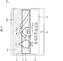
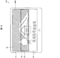
- FIG. 18 is a diagram illustrating an example of the processed image IMG2 displayed on the display unit 50.
- the display device 400 displays an image, and includes a control unit 10c (image processing device), a display unit 50, a gazing point detection sensor 60, and a storage unit 70.
- a control unit 10c image processing device
- a display unit 50 display unit 50
- a gazing point detection sensor 60 display unit 50
- a storage unit 70 storage unit 70
- the control unit 10c controls the display device 400 in an integrated manner.
- the control unit 10c has an image processing function for performing a predetermined process on the image IMG1 illustrated in FIG. 17.
- the image generating unit 14c, the attention area specifying unit 31, and the edge detecting unit 42 are provided. That is, the control unit 10c is different from the control unit 10b in that it includes an image generation unit 14c and an edge detection unit 42.
- the edge detection unit 42 reads the image data stored in the storage unit 70, detects an edge in the image IMG1 indicated by the image data by the same method as that of the object detection unit 32 of the third embodiment, and obtains the detection result. It transmits to the image generation part 14c. Unlike the object detection unit 32, the edge detection unit 42 performs only edge detection on the image IMG1, and does not detect the object included in the image IMG1.
- the image generation unit 14c performs an enhancement process on the image IMG1 over the entire attention area TA identified by the attention area identification unit 31, and performs a blurring process on the entire non-attention area. (Process P3).
- the image generation unit 14c combines the image IA generated in the process P1 and the image IC generated in the process P3, thereby processing the post-process image IMG2 as shown in FIG. Is generated.
- the image generation unit 14c determines which of the divided areas A1 to A3 is the attention area TA, and performs enhancement processing or blurring for each of the divided areas A1 to A3. Process.
- the image generation unit 14c acquires the area specifying data, and specifies that the divided area A2 is the attention area TA and the divided areas A1 and A3 are the non-attention areas. Based on the detection result of the edge detection unit 42, the image generation unit 14c performs enhancement processing on the edges included in the divided area A2 that is the attention area TA, and is included in the divided areas A1 and A3 that are non-target areas.
- An image IC is generated by performing a blurring process on the edge to be processed.
- the image generation unit 14c generates the processed image IMG2 illustrated in FIG. 18 by combining the image IA obtained by performing the blurring process on the sky region Bs and the image IC. In the post-processing image IMG2, only edges (edges other than the edges (i) and (ii) above) included in the non-processed area of the attention area TA are emphasized, and other edges are blurred.
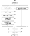
- FIG. 19 is a flowchart illustrating an example of processing in the display device 400.
- the image generation unit 14c After the processing of S23, the image generation unit 14c generates an image IC based on the detection result of the edge detection unit 42. Specifically, the image generation unit 14c performs enhancement processing on the image IMG1 in the entire attention area TA (S34) and blurring processing in the entire non-target area (S35). The image generation unit 14c generates the processed image IMG2 by synthesizing the image IA generated by the SA process and the image IC generated by the processes of S21 to 23, S34, and S35 (S28).
- process of S21 and the process of S22 and S23 may be performed in parallel, and the process of S21 may be performed after the process of S22 and S23.
- processes of S34 and S35 may be performed in parallel, or the process of S34 may be performed after the process of S35.
- processing of S21 to 23, S34 and S35 may be performed after the processing of SA, or the processing of SA may be performed after the processing of S21 to 23, S34 and S35.
- the display device 400 performs the enhancement process on the attention area TA and performs the blurring process on the non-attention area without specifying the objects Obj1 to Obj4.
- the image generation unit 14c performs enhancement processing on the entire non-processing area for the attention area TA. Therefore, the display device 400 can generate the image IC by a simpler process than the process P2 of the third embodiment. That is, the display device 400 can generate the processed image IMG2 by a simpler process than the display device 300.
- the control unit 10c may determine whether or not there is a sky region Bs that is subject to blurring processing only for the identified attention area TA, and may perform blurring processing on the sky region Bs according to the determination result.
- the relationship specifying unit 11, the empty region specifying unit 12, and the execution feasibility determining unit 13 set the target region TA specified by the target region specifying unit 31 as a processing target.
- the image generation unit 14c performs a blurring process on the non-attention area, and for the attention area TA, when it is determined that the sky area Bs is a target of the blurring process, the image generation unit 14c performs a blurring process on the sky area Bs.
- a post-processing image IMG2 is generated by performing enhancement processing for the processing region.
- the blurring process is performed on the non-attention area. For this reason, even if the result of the process P1 is preferentially applied, the blurring process is performed on the non-attention area regardless of the presence or absence of the empty area Bs. That is, in the processes P1 and P3, the blurring process may overlap when there is an empty area Bs in the non-target area. As described above, when the determination as to whether or not to perform the blurring process on the sky region Bs is not performed on the non-attention region but only on the attention region TA, the blurring processing overlaps on the non-attention region. It can be avoided. That is, it is possible to efficiently determine (specify) a region to be subjected to the blurring process in the image IMG1, and to simplify the process.
- a backlight (not shown) to be controlled may be made to coincide with the above-described area where the blurring process is performed.
- the area can be set with a degree of freedom in accordance with the image effect of the image IMG1 and the system or mechanism requirements of the display device 400.
- FIG. 20 is a diagram illustrating an example of the image IMG1 to be displayed on the display unit 50 and a plurality of divided regions C1 to C9 formed in the image IMG1.
- the nine divided regions C1 to C9 are set so that the width H of the image IMG1 is approximately equal to nine. That is, the widths hc (lengths in the vertical direction) of the divided regions C1 to C9 are all hc ⁇ H / 9.
- FIG. 21 and FIG. 22 are diagrams for explaining an example of processing of the display device 500, respectively.
- the gazing point F exists in the divided area C4.
- the gazing point F exists in the divided area C8.
- FIGS. 21 and 22 show cases where the positions of the gazing point F are different from each other.
- the attention area specifying unit 31 specifies the attention area TC based on the gazing point F as in the third and fourth embodiments.
- the attention area specifying unit 31 specifies the divided area C4 as the attention area TC.
- the attention area specifying unit 31 specifies the divided area C8 as the attention area TC.
- the attention area specifying unit 31 further specifies a neighboring area NC that is a divided area located in the vicinity of the attention area TC among the divided areas C1 to C9.
- the attention area specifying unit 31 specifies a divided area adjacent to the attention area TC in the vertical direction as the neighboring area NC.
- the neighboring area NC above the attention area TC is also referred to as an upper neighboring area NU.
- the lower neighboring area NC on the attention area TC is also referred to as a lower neighboring area NL.
- the attention area specifying unit 31 specifies the divided area C3 as the upper vicinity area NU and specifies the divided area C5 as the lower vicinity area NL. That is, the attention area specifying unit 31 specifies the divided areas C3 and C5 as neighboring areas NC with respect to the attention area TC (divided area C4).
- the attention area specifying unit 31 specifies the divided area C7 as the upper vicinity area NU and specifies the divided area C9 as the lower vicinity area NL. That is, the attention area specifying unit 31 specifies the divided areas C7 and C9 as neighboring areas NC with respect to the attention area TC (divided area C8).
- the attention area specifying unit 31 sets (specifies) the attention area TC and the neighboring area NC that have already been specified as new attention areas.
- the attention area newly set by the attention area specifying unit 31 is referred to as a new attention area TC2.
- the attention area specifying unit 31 sets the divided area C4 as the attention area TC and the divided areas C3 and C5 as the neighboring areas NC as the new attention area TC2. That is, the attention area specifying unit 31 sets the three divided areas C3 to C5 as the new attention area TC2, and the six divided areas (the divided areas C1 to C2 and C6 to C9) excluding the new attention area TC2 as the non- attention areas. Set each.
- the attention area specifying unit 31 sets the divided area C8 as the attention area TC and the divided areas C7 and C9 as the neighboring areas NC as the new attention area TC2. That is, the attention area specifying unit 31 sets the three divided areas C7 to C9 as the new attention area TC2 and the six divided areas (the divided areas C1 to C6) excluding the new attention area TC2 as the non- attention areas, respectively. .
- the processing P1 and the processing P2 or P3 described above are performed as in the third and fourth embodiments, and the processed image IMG2 is generated by combining these processing results.
- the attention area TC is likely to change as the gazing point F moves. For this reason, in the processed image IMG2, there is a concern that the vicinity of the boundary may appear unnatural to the viewer 90. This is also remarkable when the number of divided areas is small.
- the display device 500 is provided with a larger number of divided regions than the display devices 300 and 400 described above, and adds a region NC near the region of interest TC as a margin to the region of interest TC.
- the region of interest TC2 is set.
- the enhancement process can be performed for the non-processing area. Therefore, even when the gazing point F moves, the vicinity of the boundary of the attention area TC The possibility that the viewer 90 looks unnatural can be reduced.
- the gazing point F moves outside the attention area TC, the moved gazing point F exists inside the neighboring area NC. This is because it is expected.
- the non-processed region included in the attention region (new attention region TC2) wider than the display devices 300 and 400 can be the target of the enhancement processing, and thus there is no sense of incongruity. It is possible to provide the viewer 90 with the processed image IMG2.
- the case where the number of divided areas is nine is exemplified, but the number of divided areas is not limited to this, and may be five or more.
- the case where the divided area adjacent to the attention area TC in the vertical direction is specified as the neighboring area NC is exemplified, but the method of specifying the neighboring area NC is not limited to this.
- the attention area specifying unit 31 specifies up to N1 divided areas when viewed upward from the attention area TC as the upper neighboring area NU, and up to N2 divided areas when viewed downward from the attention area TC. May be specified as the lower vicinity region NU.
- the attention area specifying unit 31 may specify the upper neighboring area NU composed of N1 divided areas and the lower neighboring area NL composed of N2 divided areas as the neighboring area NC.
- the values of N1 and N2 may be set in advance by the designer of the display device 500 according to the number of divided areas. That is, the extent of the “nearby” range from the attention area TC may be determined as appropriate by the designer of the display device 500. Further, the values of N1 and N2 may be set so as to be changeable by the user of the display device 500.
- control blocks (particularly the control units 10, 10a, 10b, and 10c) of the display devices 100, 100a, 200, 300, 400, and 500 are realized by a logic circuit (hardware) formed in an integrated circuit (IC chip) or the like. Alternatively, it may be realized by software using a CPU (Central Processing Unit).
- a logic circuit hardware
- IC chip integrated circuit
- CPU Central Processing Unit
- the display devices 100, 100a, 200, 300, 400, and 500 are configured such that a CPU that executes instructions of a program that is software that realizes each function, and the program and various data can be read by a computer (or CPU)
- a ROM (Read Only Memory) or a storage device (these are referred to as “recording media”), a RAM (Random Access Memory) for expanding the program, and the like are provided.
- the objective of this indication is achieved when a computer (or CPU) reads and runs the said program from the said recording medium.
- a “non-temporary tangible medium” such as a tape, a disk, a card, a semiconductor memory, a programmable logic circuit, or the like can be used.
- the program may be supplied to the computer via an arbitrary transmission medium (such as a communication network or a broadcast wave) that can transmit the program.
- an arbitrary transmission medium such as a communication network or a broadcast wave
- one aspect of the present disclosure can also be realized in the form of a data signal embedded in a carrier wave in which the program is embodied by electronic transmission.
- the image processing apparatus specifies a sky area (Bs, Bs1, Bs2, Bsn) that corresponds to the sky in the display target image (image IMG1). Based on the color of the sky region specified by the region specifying unit (12, 12a) and the sky region specifying unit, an execution feasibility determining unit (13, 13a) for determining whether to perform the blurring process on the sky region. ) And an image generation unit (14, 14b, which generates a post-processing image (IMG2) by performing a blurring process on the sky area when the execution determination unit determines that the blurring process is to be performed. 14c).
- a sky area Bs, Bs1, Bs2, Bsn
- an execution feasibility determining unit 13, 13a
- an image generation unit which generates a post-processing image (IMG2) by performing a blurring process on the sky area when the execution determination unit determines that the blurring process is to be performed. 14c).
- the blurring process is performed on the sky area based on the determination result. For example, when the sky region has a specific color, it is highly likely that the sky region is a surface color. By performing the blurring process on the sky region that is the surface color, it is possible to bring the appearance unique to the surface color, that is, the sky region closer to a psychological appearance.
- the image processing device it is possible to generate a post-processing image including a sky region that is close to the actual appearance in the natural world.
- the sky area specifying unit specifies the distant view area as the sky area when the display target image includes a distant view area. May be.
- the distant view area included in the display target image can be specified as the sky area.
- the image processing apparatus (10) in the second aspect, includes a plurality of divided regions (A1 to A3, B1 to B6, and the like) formed by dividing the display target image in the vertical direction.
- the sky region specifying unit includes a relationship specifying unit (11) for specifying the relationship between the brightness of each of the plurality of pixels constituting the display target image and the number of pixels having the brightness.
- the number of the pixels indicated by the peak in the graph (lightness distribution) expressing the relationship for each of the plurality of divided regions specified by the relationship specifying unit is positioned on the upper side in the display target image. When there is a set of divided areas decreasing from the divided area toward the divided area located below, or when the number of pixels is constant in the display target image
- the region formed by the pixels corresponding to the peak may be specified as the distant view area.
- the distant view area When the distant view area is included in the display target image, the distant view area is generally included more in the upper side than the lower side of the display target image. In general, the width of the graph in the sky region is relatively narrow. Considering these points, when the number of pixels indicated by the peak is reduced or constant as described above, a distant view area as a sky area may be included in the display target image. high.
- the sky area specifying unit specifies pixels constituting the distant view area
- the execution determination unit (13) is configured to specify the sky area specifying unit.
- the distant area is a sky area having a specific color
- blur processing is performed on the sky area.
- a sky region for example, a blue sky
- a surface color can be brought close to an actual appearance in the natural world.
- the image processing apparatus (10a) is configured to display the display target image for each of the plurality of divided regions formed by dividing the display target image in the vertical direction in aspect 2.
- Each of the colors of a plurality of constituting pixels is classified into one of a plurality of predetermined colors, and includes a pixel counting unit (21) that counts the number of pixels for each of the predetermined colors. 12a), in any one of the predetermined colors, the pixel counting unit moves from the upper divided area (A1) to the lower divided area (A3) in the display target image.
- the region that is formed may be specified as the distant view area.
- the distant view area is generally included more in the upper side than the lower side of the display target image.
- the color distribution in the sky region is relatively narrow. Considering these points, when the number of pixels classified into any one of the predetermined colors as described above is reduced or constant, a distant view area as a sky area is displayed. There is a high possibility that it is included in the target image.
- the determination can be performed relatively easily.
- the execution determination unit (13a) is configured such that the predetermined color corresponding to the pixels constituting the specified far-field region is a specific color. In some cases, it may be determined that the blurring process is performed on the sky region.
- the blurring process can be performed on a distant view area as a sky area having a specific color. For this reason, in the processed image, for example, a sky region (for example, a blue sky) that is a surface color can be brought close to an actual appearance in the natural world.
- a sky region for example, a blue sky
- the execution determination unit may include an empty area included in the upper divided area (A1 or A2) among the plurality of divided areas.
- the contact area with the empty area included in the lower divided area (A2 or A3) adjacent to the upper divided area is less than a predetermined amount, only the empty area included in the upper divided area is blurred. It may be a target.
- the sky area may not be an area corresponding to the actual sky, but may indicate an object having a specific color that is different from the sky.
- the contact area is less than the predetermined amount, it is determined that the object as described above exists in the lower divided area, and the blurring process is not performed on the object. Can be. For this reason, it is possible to prevent a problem such as performing blurring processing unintentionally even for an object whose entity can be recognized.
- the image is positioned above the divided area (B5, B6) located on the lower side among the plurality of divided areas.
- the divided regions (B1 to B4) to be performed may be shorter in the vertical direction (width ha ⁇ width hb).
- the empty area is often included above the display target image. For this reason, as in the configuration described above, it is possible to specify the empty region with high accuracy by shortening the length in the vertical direction in the upper divided region than in the lower divided region.
- a display device 300, 400, 500 having a display surface (display unit 50) for displaying the display target image;
- the display target image can be connected to a sensor (gaze point detection sensor 60) that detects the gaze point (F) of the viewer (90) on the display surface in a communicable manner and is based on the gaze point detected by the sensor.
- a sensor gaze point detection sensor 60
- the attention area specifying unit for specifying the attention area (TA, TC, new attention area TC2) that is the divided area that the viewer is paying attention to (31), and the image generation unit (14b, 14c) applies to at least a part of the non-process area other than the sky area to be subjected to the blurring process in the attention area. Enhancement processing may be performed.
- the image generation unit can perform the enhancement processing on the non-processing region based on the result of the attention region specifying unit specifying the attention region based on the gazing point.
- the image processing apparatus simply identifies which divided area of the display surface the viewer is watching, and the portion where the emphasis process is performed in the non-process area and the other areas where the emphasis process is not performed. It is possible to generate a post-processing image that causes a relative difference in appearance between the portions.
- the image processing apparatus can generate a post-processed image that provides a stereoscopic effect close to the actual appearance in the natural world without performing high-precision detection of the point of sight. Therefore, it is possible to generate a post-processing image that provides the above three-dimensional effect with a simple process.
- a display device (100, 100a, 200, 300, 400, 500) according to aspect 10 of the present disclosure includes the image processing device according to any one of aspects 1 to 9.
- control method of the image processing device includes a sky region specifying step of specifying a sky region corresponding to the sky in the display target image, and a color of the sky region specified in the sky region specifying step.
- a sky region specifying step of specifying a sky region corresponding to the sky in the display target image
- a color of the sky region specified in the sky region specifying step Based on the execution possibility determination step for determining whether or not to perform the blurring process for the sky region, and the blur processing for the sky region when it is determined that the blurring process is to be performed in the execution permission determination step.
- An image generation step of generating a post-processing image by performing.
- the image processing apparatus may be realized by a computer.
- the image processing apparatus is operated on each computer by causing the computer to operate as each unit (software element) included in the image processing apparatus.
- An image processing program of an image processing apparatus to be realized in this manner and a computer-readable recording medium on which the image processing program is recorded also fall within the scope of the present disclosure.
Landscapes
- Engineering & Computer Science (AREA)
- Multimedia (AREA)
- Signal Processing (AREA)
- Physics & Mathematics (AREA)
- Computer Hardware Design (AREA)
- General Physics & Mathematics (AREA)
- Theoretical Computer Science (AREA)
- Controls And Circuits For Display Device (AREA)
Abstract
Le but de la présente invention est de générer une image qui ressemble à un objet tel qu'il apparaîtrait réellement dans la nature. L'invention concerne un dispositif d'affichage (100) comprenant : une unité d'identification de région de ciel (12) qui identifie une région de ciel (Bs) dans une image (IMG1) ; une unité d'évaluation d'exécution (13) qui, sur la base de la couleur de la région du ciel, évalue s'il faut effectuer un traitement de flou sur la région du ciel ; une unité de génération d'image (14) qui, s'il a été évalué que le traitement de flou doit être effectué, génère une image traitée (IMG2) par réalisation du traitement de flou sur la région du ciel.
Applications Claiming Priority (2)
| Application Number | Priority Date | Filing Date | Title |
|---|---|---|---|
| JP2016-236910 | 2016-12-06 | ||
| JP2016236910 | 2016-12-06 |
Publications (1)
| Publication Number | Publication Date |
|---|---|
| WO2018105228A1 true WO2018105228A1 (fr) | 2018-06-14 |
Family
ID=62491868
Family Applications (1)
| Application Number | Title | Priority Date | Filing Date |
|---|---|---|---|
| PCT/JP2017/036609 Ceased WO2018105228A1 (fr) | 2016-12-06 | 2017-10-10 | Dispositif de traitement d'image, dispositif d'affichage, procédé de commande de dispositif de traitement d'image et programme de commande |
Country Status (1)
| Country | Link |
|---|---|
| WO (1) | WO2018105228A1 (fr) |
Citations (4)
| Publication number | Priority date | Publication date | Assignee | Title |
|---|---|---|---|---|
| JP2006140594A (ja) * | 2004-11-10 | 2006-06-01 | Pentax Corp | デジタルカメラ |
| JP2012109725A (ja) * | 2010-11-16 | 2012-06-07 | Canon Inc | 立体映像処理装置および立体映像処理方法 |
| JP2013254358A (ja) * | 2012-06-07 | 2013-12-19 | Sony Corp | 画像処理装置、画像処理方法およびプログラム |
| WO2014041860A1 (fr) * | 2012-09-14 | 2014-03-20 | ソニー株式会社 | Dispositif de traitement d'image, procédé de traitement d'image et programme |
-
2017
- 2017-10-10 WO PCT/JP2017/036609 patent/WO2018105228A1/fr not_active Ceased
Patent Citations (4)
| Publication number | Priority date | Publication date | Assignee | Title |
|---|---|---|---|---|
| JP2006140594A (ja) * | 2004-11-10 | 2006-06-01 | Pentax Corp | デジタルカメラ |
| JP2012109725A (ja) * | 2010-11-16 | 2012-06-07 | Canon Inc | 立体映像処理装置および立体映像処理方法 |
| JP2013254358A (ja) * | 2012-06-07 | 2013-12-19 | Sony Corp | 画像処理装置、画像処理方法およびプログラム |
| WO2014041860A1 (fr) * | 2012-09-14 | 2014-03-20 | ソニー株式会社 | Dispositif de traitement d'image, procédé de traitement d'image et programme |
Similar Documents
| Publication | Publication Date | Title |
|---|---|---|
| US11501479B2 (en) | Virtual make-up apparatus and virtual make-up method | |
| US11545108B2 (en) | Modifying rendered image data based on ambient light from a physical environment | |
| KR20240112853A (ko) | 물리적 표면들에 대한 가상 콘텐츠의 앵커링 | |
| US11128909B2 (en) | Image processing method and device therefor | |
| CN110488969A (zh) | 相对于实际物理对象定位虚拟对象的技术 | |
| KR20160021607A (ko) | 배경 화면을 디스플레이하는 방법 및 장치 | |
| US11375166B2 (en) | Selective colorization of thermal imaging | |
| US12316821B2 (en) | Multiview display system and method with adaptive background | |
| KR20220139261A (ko) | 물리적 환경으로부터의 광 중첩에 기초한 디스플레이 동작 파라미터들의 수정 | |
| CN105791793A (zh) | 图像处理方法及其电子装置 | |
| JP2016142988A (ja) | 表示装置及び表示制御プログラム | |
| US11877088B2 (en) | Contrast enhanced images composited with artificial colorization | |
| US11657478B1 (en) | Systems and methods for dynamically rendering three-dimensional images with varying detail to emulate human vision | |
| WO2017221509A1 (fr) | Dispositif de traitement d'images, dispositif d'affichage, procédé de commande de dispositif de traitement d'images et programme de commande | |
| TWI541761B (zh) | 影像處理方法及其電子裝置 | |
| CN102868905A (zh) | 图像处理设备、图像处理方法和程序 | |
| KR102005526B1 (ko) | 증강 현실 표시 방법 및 장치 | |
| JP7172066B2 (ja) | 情報処理装置及びプログラム | |
| JP7125847B2 (ja) | 3dモデル表示装置、3dモデル表示方法及び3dモデル表示プログラム | |
| Fukiage | Human-centric Image Rendering for Natural and Comfortable Viewing--Image Optimization Based on Human Visual Information Processing Models | |
| HK40088146A (zh) | 使用自适应背景的多视图显示系统及方法 | |
| KR20230066986A (ko) | 혼합 현실과 상호작용하기 위한 방법 및 이를 위한 장치 | |
| CN117597919A (zh) | 处理图像的方法和设备 |
Legal Events
| Date | Code | Title | Description |
|---|---|---|---|
| 121 | Ep: the epo has been informed by wipo that ep was designated in this application |
Ref document number: 17877399 Country of ref document: EP Kind code of ref document: A1 |
|
| NENP | Non-entry into the national phase |
Ref country code: DE |
|
| 122 | Ep: pct application non-entry in european phase |
Ref document number: 17877399 Country of ref document: EP Kind code of ref document: A1 |
|
| NENP | Non-entry into the national phase |
Ref country code: JP |