WO2018105395A1 - Dispositif de chauffage par induction, dispositif d'ajustement par rétraction et procédé de chauffage par induction - Google Patents
Dispositif de chauffage par induction, dispositif d'ajustement par rétraction et procédé de chauffage par induction Download PDFInfo
- Publication number
- WO2018105395A1 WO2018105395A1 PCT/JP2017/041962 JP2017041962W WO2018105395A1 WO 2018105395 A1 WO2018105395 A1 WO 2018105395A1 JP 2017041962 W JP2017041962 W JP 2017041962W WO 2018105395 A1 WO2018105395 A1 WO 2018105395A1
- Authority
- WO
- WIPO (PCT)
- Prior art keywords
- temperature
- induction heating
- heating element
- flange
- joining
- Prior art date
- Legal status (The legal status is an assumption and is not a legal conclusion. Google has not performed a legal analysis and makes no representation as to the accuracy of the status listed.)
- Ceased
Links
Images









Classifications
-
- B—PERFORMING OPERATIONS; TRANSPORTING
- B23—MACHINE TOOLS; METAL-WORKING NOT OTHERWISE PROVIDED FOR
- B23P—METAL-WORKING NOT OTHERWISE PROVIDED FOR; COMBINED OPERATIONS; UNIVERSAL MACHINE TOOLS
- B23P11/00—Connecting or disconnecting metal parts or objects by metal-working techniques not otherwise provided for
- B23P11/02—Connecting or disconnecting metal parts or objects by metal-working techniques not otherwise provided for by first expanding and then shrinking or vice versa, e.g. by using pressure fluids; by making force fits
-
- B—PERFORMING OPERATIONS; TRANSPORTING
- B23—MACHINE TOOLS; METAL-WORKING NOT OTHERWISE PROVIDED FOR
- B23Q—DETAILS, COMPONENTS, OR ACCESSORIES FOR MACHINE TOOLS, e.g. ARRANGEMENTS FOR COPYING OR CONTROLLING; MACHINE TOOLS IN GENERAL CHARACTERISED BY THE CONSTRUCTION OF PARTICULAR DETAILS OR COMPONENTS; COMBINATIONS OR ASSOCIATIONS OF METAL-WORKING MACHINES, NOT DIRECTED TO A PARTICULAR RESULT
- B23Q17/00—Arrangements for observing, indicating or measuring on machine tools
-
- H—ELECTRICITY
- H05—ELECTRIC TECHNIQUES NOT OTHERWISE PROVIDED FOR
- H05B—ELECTRIC HEATING; ELECTRIC LIGHT SOURCES NOT OTHERWISE PROVIDED FOR; CIRCUIT ARRANGEMENTS FOR ELECTRIC LIGHT SOURCES, IN GENERAL
- H05B6/00—Heating by electric, magnetic or electromagnetic fields
- H05B6/02—Induction heating
-
- H—ELECTRICITY
- H05—ELECTRIC TECHNIQUES NOT OTHERWISE PROVIDED FOR
- H05B—ELECTRIC HEATING; ELECTRIC LIGHT SOURCES NOT OTHERWISE PROVIDED FOR; CIRCUIT ARRANGEMENTS FOR ELECTRIC LIGHT SOURCES, IN GENERAL
- H05B6/00—Heating by electric, magnetic or electromagnetic fields
- H05B6/02—Induction heating
- H05B6/06—Control, e.g. of temperature, of power
-
- H—ELECTRICITY
- H05—ELECTRIC TECHNIQUES NOT OTHERWISE PROVIDED FOR
- H05B—ELECTRIC HEATING; ELECTRIC LIGHT SOURCES NOT OTHERWISE PROVIDED FOR; CIRCUIT ARRANGEMENTS FOR ELECTRIC LIGHT SOURCES, IN GENERAL
- H05B6/00—Heating by electric, magnetic or electromagnetic fields
- H05B6/02—Induction heating
- H05B6/10—Induction heating apparatus, other than furnaces, for specific applications
Definitions
- the present invention relates to an induction heating device that induction-heats a heating element made of a magnetic material, a shrink fitting device including the induction heating device, and an induction heating method.
- shrink fitting is known as a joining method for joining two joining objects of a first member and a second member having a joining insertion portion into which the first member is inserted (for example, Patent Literature 1). 1).
- the second member is preheated and thermally expanded to expand the diameter of the joining insert, the first member is inserted in the expanded state, and the diameter of the joining insert is reduced during cooling. It is a technology that joins them together.
- the second member (tool holding portion) is made of a nonmagnetic material.
- a heating element heatating ring
- the second member is heated by heat transfer from the heating element.
- the heating efficiency of the heating element is extremely high. That is, the heating rate of the heating element during induction heating is extremely fast. For this reason, there is a problem that the variation in the timing of stopping the induction heating greatly affects the variation in the temperature of the heating element at the time of the stopping, and it is difficult to set the heating element to a temperature near the target temperature. For this reason, there is a demand for a technique capable of easily setting the heating element to a temperature near the target temperature while rapidly raising the temperature of the heating element.
- the present invention has been made in view of the above, and it is possible to easily set the heating element to a temperature in the vicinity of the target temperature while rapidly raising the temperature of the heating element, a shrink fitting device, And it aims at providing the induction heating method.
- an induction heating device is an induction heating device that induction-heats a heating element made of a magnetic material, and is wound so as to cover the heating element.
- An induction heating coil and a power feeding unit that feeds a high-frequency current to the induction heating coil and raises the heating element to a target temperature by induction heating, the target temperature being higher than the Curie temperature of the heating element It is characterized by being set to temperature.
- the induction heating device further includes a temperature measuring unit that measures the temperature of the heating element, and the power feeding unit has a temperature of the heating element measured by the temperature measuring unit. When the target temperature is reached, feeding of high-frequency current to the induction heating coil is stopped.
- the temperature measuring unit is a radiation thermometer.
- the temperature measuring unit is a thermocouple.
- the induction heating device further includes a time measuring unit that measures an elapsed time since the start of feeding of the high-frequency current to the induction heating coil, and the feeding unit includes the time The power supply of the high frequency current to the induction heating coil is stopped when the elapsed time measured by the measurement unit reaches a preset time.
- the shrink-fitting device according to the present invention is a shrink-fitting device that joins two joining objects of a first member and a second member having a joining insertion portion into which the first member is inserted by shrink fitting.
- the above-described induction heating device for controlling the temperature of the second member is provided.
- the induction heating device includes the heating element, and transmits the heat of the heating element to the second member made of a nonmagnetic material, so that the second The temperature of the member is controlled.
- the second member is an aluminum alloy
- the heating element is Kovar
- the induction heating method according to the present invention is an induction heating method in which a heating element made of a magnetic material is induction-heated, and a high-frequency current is fed to an induction heating coil wound so as to cover the heating element.
- a power supply step of heating the heating element to a target temperature by heating is provided, and the target temperature is set to a temperature higher than the Curie temperature of the heating element.
- the induction heating device the shrink fitting device, and the induction heating method according to the present invention, the effect that the heating element can be easily set to a temperature near the target temperature while the heating element is quickly heated. Play.
- FIG. 1 is a diagram showing two joining objects according to the first embodiment.
- FIG. 2 is a diagram illustrating two objects to be joined according to the first embodiment.
- FIG. 3 is a diagram showing the shrink-fitting device according to the first embodiment.
- FIG. 4 is a flowchart showing a joining method of two joining objects using the shrink-fitting device shown in FIG.
- FIG. 5 is a diagram showing the temperature transition of the heating element and the flange when the joining method shown in FIG. 4 is performed.
- FIG. 6 is a diagram showing a shrink-fitting device according to the first modification of the first embodiment.
- FIG. 7 is a diagram showing a shrink-fitting device according to the second modification of the first embodiment.
- FIG. 8 is a diagram showing a shrink-fitting device according to the second embodiment.
- FIG. 1 is a diagram showing two joining objects according to the first embodiment.
- FIG. 2 is a diagram illustrating two objects to be joined according to the first embodiment.
- FIG. 3 is a diagram showing
- FIG. 9 is a flowchart showing a joining method of two joining objects using the shrink-fitting device shown in FIG.
- FIG. 10 is a flowchart showing the bonding method according to the third embodiment.
- FIG. 11A is a diagram for explaining the joining method shown in FIG.
- FIG. 11B is a diagram illustrating the bonding method illustrated in FIG. 10.
- FIG. 11C is a diagram for explaining the joining method illustrated in FIG. 10.
- FIG. 11D is a diagram for explaining the joining method illustrated in FIG. 10.
- FIG. 11E is a view for explaining the joining method shown in FIG. 10.
- 12 is a diagram illustrating changes in the inner diameter dimension of the installation insertion portion, the outer diameter dimension of the flange, and the inner diameter dimension of the bonding insertion portion when the joining method illustrated in FIG. 10 is performed.
- FIG. 13 is a diagram for explaining the effect of the third embodiment.
- FIG. 14 is a diagram for explaining the effect of the third embodiment.
- FIG. 15 is a diagram for explaining
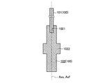
- FIG. 1 is a perspective view of two joining objects 100.
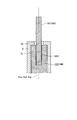
- FIG. 2 is a cross-sectional view of the two joining objects 100 cut along a cut surface along the central axes Axs and Axf of the two joining objects 100.
- 1 and 2 show a state in which the objects to be joined 100 are joined to each other for convenience of explanation.
- the two joining objects 100 include a shaft member 101 and a flange 102.
- the shaft member 101 corresponds to a first member according to the present invention, and is made of, for example, a titanium alloy having a long cylindrical shape as shown in FIG. 1 or FIG.
- the flange 102 corresponds to the second member according to the present invention, and is made of a nonmagnetic material such as an aluminum alloy having a long, substantially cylindrical shape as shown in FIG. 1 or FIG. Then, on the center axis Axf (FIG. 2) of the flange 102, the shaft member 101 is depressed from one end (upper end in FIG. 2) to the other end (lower end in FIG. 2). A joining insertion portion 1021 having a circular cross section is inserted.
- the inner diameter dimension of the bonding insertion portion 1021 at room temperature is set smaller than the outer diameter dimension of the shaft member 101 at room temperature. Further, in the flange 102, a large diameter portion 1022 having a larger diameter than other portions is formed at a substantially central portion in the longitudinal direction, as shown in FIG.
- the shaft member 101 and the flange 102 described above are joined to each other in a state where the shaft member 101 is inserted into the joining insertion portion 1021 as shown in FIG. 1 or FIG.
- the shaft member 101 and the flange 102 joined to each other are used, for example, in an ultrasonic treatment instrument that applies ultrasonic energy to a living tissue to treat the living tissue.
- the shaft member 101 and the flange 102 joined to each other are configured to contact the living tissue from one end (the end on the lower side in FIGS. 1 and 2) of the ultrasonic vibration generated by the ultrasonic vibrator. It is used as a probe that transmits to the end (the upper end in FIGS. 1 and 2).
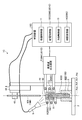
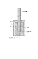
- FIG. 3 is a view showing the shrink-fitting device 1.
- the flange installation member 3, the flange 102, and the heating element 5 are cut along cut surfaces along the respective central axes Ax1, Axf, Axj.
- the shrink fitting device 1 includes a base 2, a flange installation member 3, a holding device 4, a heating element 5, an induction heating coil 6, a high frequency output device 7, and a temperature measuring device 8. And a cooling device 9 and a control device 10.
- the base 2 is a portion that supports the flange installation member 3 and the holding device 4 on a flat upper surface.
- the flange installation member 3 is fixed to the upper surface of the base 2 and is a part where the flange 102 is installed.
- the other end side of the flange 102 (the end side where the joining insertion portion 1021 is not formed) is inserted. It has a substantially cylindrical shape. As shown in FIG. 3, the other end of the flange 102 is inserted into the flange installation member 3 and the large-diameter portion 1022 is locked to the upper surface of the flange installation member 3, and the center axis Axf of the flange 102 is a flange.
- the installation member 3 is installed in a posture that matches the center axis Ax1.
- the holding device 4 is a device that holds the shaft member 101 and inserts the shaft member 101 into the joining insertion portion 1021.
- the holding device 4 includes a support column 41, a moving unit 42, and a holding unit 43.
- the support column 41 is formed of a columnar body erected on the upper surface of the base 2, and is a portion that supports the moving unit 42 and the holding unit 43.
- the moving unit 42 is configured to be movable along the support column 41.
- the moving unit 42 moves up and down along the support column 41 when a driving unit (not shown) such as a motor is driven under the control of the control device 10.
- the holding portion 43 is a portion that is fixed to the moving portion 42 and holds the shaft member 101 in a posture in which the center axis Axs of the shaft member 101 matches the center axis Ax1 of the flange installation member 3.
- the heating element 5 is made of a magnetic material such as Kovar having a cylindrical shape. Then, on the central axis Axj of the heating element 5, it is recessed from one end (the lower end in FIG. 3) toward the other end, and one end of the flange 102 (the end where the joining insertion portion 1021 is formed).
- the insertion portion 51 for installation having a circular cross section is inserted. That is, as shown in FIG. 3, the heating element 5 has one end of the flange 102 inserted into the installation insertion portion 51 in a posture in which the center axis Axj of the heating element 5 matches the center axis Axf of the flange 102. It is installed to cover the side. Further, on the central axis Axj of the heating element 5, an insertion hole that penetrates the bottom of the installation insertion portion 51 and inserts the shaft member 101 from the outside of the heating element 5 into the installation insertion portion 51. 52 is formed.
- the induction heating coil 6 is wound so as to cover the outer peripheral surface of the heating element 5 with a predetermined gap with respect to the outer peripheral surface of the heating element 5 installed on the flange 102.
- the high frequency output device 7 is electrically connected to the induction heating coil 6 and supplies a high frequency current to the induction heating coil 6 under the control of the control device 10. And according to supply of the high frequency current to the induction heating coil 6, the heat generating body 5 which is a magnetic material is induction-heated.
- the temperature measuring device 8 corresponds to a temperature measuring unit according to the present invention, and measures the temperature of the heating element 5 under the control of the control device 10. Then, the temperature measuring device 8 outputs a signal corresponding to the measured temperature to the control device 10.
- the temperature measuring device 8 is composed of a radiation thermometer.
- the cooling device 9 cools the heating element 5 and the flange 102 under the control of the control device 10.
- the cooling device 9 is configured to cool the heating element 5 and the flange 102 by air cooling (air blow).
- the cooling device 9 is not limited to air cooling, and liquid cooling may be adopted.
- the cooling device 9 is not limited to the configuration in which the heating element 5 and the flange 102 are actively cooled, but the cooling device 9 is omitted, and a configuration in which the heating element 5 and the flange 102 are cooled in the atmosphere is adopted. It doesn't matter.
- the control device 10 includes a CPU (Central Processing Unit) and the like, and controls the shrink-fitting device 1 as a whole according to a predetermined control program. As illustrated in FIG. 3, the control device 10 includes a movement control unit 11, a power supply control unit 12, and a cooling control unit 13. The movement control unit 11 controls the operation of a driving unit (not shown) such as a motor, and moves the moving unit 42 of the holding device 4 up and down.
- the power supply controller 12 supplies a high-frequency current from the high-frequency output device 7 to the induction heating coil 6 and raises the heating element 5 to a target temperature by induction heating.
- the electric power feeding control part 12 stops the drive of the high frequency output device 7 at the time of the temperature of the heat generating body 5 measured with the temperature measuring device 8 becoming target temperature (heat generating body). 5 induction heating is stopped).
- the target temperature described above is set higher than the Curie temperature of the heating element 5 (for example, 435 ° C. in the case of Kovar).
- the cooling control unit 13 controls the operation of the cooling device 9 and cools the heating element 5 and the flange 102 by air cooling.
- the heating element 5, the induction heating coil 6, the high-frequency output device 7, the temperature measuring device 8, and the power feeding control unit 12 described above correspond to the induction heating device 200 (FIG. 3) according to the present invention.
- the high-frequency output device 7 and the power supply control unit 12 correspond to the power supply unit 201 (FIG. 3) according to the present invention.
- FIG. 4 is a flowchart showing a method for joining the objects to be joined 100 using the shrink fitting device 1.
- the operator installs the two joining objects 100 in the shrink-fitting device 1 (Step S1) and installs the heating element 5 on the flange 102 (Step S2).
- the shaft member 101, the flange 102, and the central axes Axs, Axf, and Axj of the heating element 5 are in a mutually matched state (FIG. 3).
- the operator presses a switch (not shown) provided in the shrink-fitting device 1 and starting a control operation by the control device 10 (step S3).
- the control apparatus 10 performs the control shown below by the said switch being pressed.
- the power supply control unit 12 supplies a high-frequency current having a constant output from the high-frequency output device 7 to the induction heating coil 6 and starts induction heating of the heating element 5 (step S4).
- the control device 10 operates the temperature measuring device 8 and starts measuring the temperature of the heating element 5 (step S5).
- the electric power feeding control part 12 always monitors whether the temperature of the heat generating body 5 measured with the temperature measuring device 8 became target temperature (step S6). If it is determined that the temperature of the heating element 5 has reached the target temperature (step S6: Yes), the power supply control unit 12 stops driving the high-frequency output device 7 (stops induction heating of the heating element 5) (step). S7).
- Step S7 the control device 10 ends the temperature measurement of the heating element 5 by the temperature measuring device 8 (step S8).
- Steps S4 to S8 described above correspond to the induction heating method (power feeding step) according to the present invention.
- the movement control unit 11 controls the operation of a driving unit (not shown) such as a motor, lowers the moving unit 42 of the holding device 4, and inserts the shaft member 101 into the joining insertion unit 1021 (Ste S9).
- the cooling control unit 13 controls the operation of the cooling device 9, and cools the heating element 5 and the flange 102 by air cooling for a predetermined time (step S10).
- the insertion part 1021 for joining shrinks by this cooling. That is, the objects 100 to be joined are joined.
- the movement control unit 11 controls the operation of a driving unit (not shown) such as a motor to raise the moving unit 42 of the holding device 4 (step S11).
- the operator removes the joined work in which the joining objects 100 are joined from the holding portion 43 of the holding device 4 (step S12).
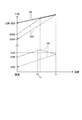
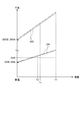
- FIG. 5 is a diagram showing the temperature transition of the heating element 5 and the flange 102 when the joining method shown in FIG. 4 is performed. Specifically, in FIG. 5, the temperature transition of the heating element 5 is indicated by a one-dot chain line, and the temperature transition of the flange 102 is indicated by a two-dot chain line. Further, in FIG. 5, the temperature transition when the Curie temperature Tc of the heating element 5 is higher than the target temperature Tt (when different from the first embodiment) is indicated by a broken line.
- step S4 when induction heating of the heating element 5 is started, the heating element 5 self-heats due to the generation of eddy current and is heated at a substantially constant rate of temperature rise (dashed line in FIG. 5). .
- the flange 102 is heated by heat transfer from the heating element 5, and thus is heated at substantially the same heating rate as the heating element 5 although there is a temperature difference between the flange 102 and the heating element 5 (FIG. 5 two-dot chain line).
- the heating element 5 is a magnetic material, but has a Curie temperature Tc (FIG. 5). Further, the target temperature Tt (FIG. 5) of the heating element 5 is set higher than the Curie temperature Tc of the heating element 5. For this reason, the heating element 5 reaches the Curie temperature Tc before reaching the target temperature Tt. When the heating element 5 reaches the Curie temperature Tc, the magnetism is lost, and after the temperature reaches the Curie temperature Tc, the rate of temperature increase by induction heating is abruptly slowed (dashed line in FIG. 5).
- the heating rate is rapidly reduced after the heating element 5 reaches the Curie temperature Tc (two-dot chain line in FIG. 5). Further, the heating element 5 reaches the target temperature Tt in a state where the temperature rising rate after the time when the Curie temperature Tc is reached is slow. In steps S6 and S7, induction heating of the heating element 5 is stopped when the temperature of the heating element 5 reaches the target temperature Tt (time T0 (FIG. 5)).
- the induction heating device 200 includes the heating element 5, the induction heating coil 6, the temperature measuring device 8, and the power feeding unit 201 described above.
- the target temperature Tt is set to a temperature higher than the Curie temperature Tc of the heating element 5. For this reason, as shown in FIG. 5, induction heating of the heating element 5 can be stopped in a state where the temperature increase rate after the time when the temperature of the heating element 5 reaches the Curie temperature Tc is slow. As a result, as shown in FIG. 5, when the induction heating of the heating element 5 is stopped at a timing shifted by the time Te before and after the time T0 when the temperature of the heating element 5 reaches the target temperature Tt.
- the temperature of the heating element 5 at the time of the stop is within a relatively narrow temperature range Td centered on the target temperature Tt.
- the Curie temperature Tc of the heating element 5 is higher than the target temperature Tt (when different from the first embodiment)
- the heating rate of the heating element 5 is fast as shown by the broken line in FIG. In the state, it is necessary to stop the induction heating of the heating element 5.
- induction heating of the heating element 5 has been stopped at a timing shifted by a time Te before and after the time T0 ′ when the temperature of the heating element 5 has reached the target temperature Tt.
- the temperature of the heating element 5 at the time of stoppage does not fall within the relatively narrow temperature range Td centered on the target temperature Tt described above, and is a relatively wide temperature range Td ′ centered on the target temperature Tt. It becomes the temperature inside.
- the heating element 5 is easily set to a temperature in the vicinity of the target temperature Tt while the heating element 5 is rapidly heated by induction heating. There is an effect that it is possible.
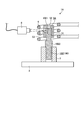
- FIG. 6 is a diagram showing a shrink-fitting device 1A according to the first modification of the first embodiment. 6 is a diagram corresponding to FIG. 3, but the illustration of the holding device 4, the high-frequency output device 7, the cooling device 9, and the control device 10 is omitted for convenience of explanation.
- the temperature measuring device 8 measures the temperature of the heating element 5, but is not limited to this, and the shrink-fitting according to the first modification shown in FIG. 6.
- a configuration for measuring the temperature of the flange 102 as in the apparatus 1A may be adopted. Specifically, as shown in FIG.
- the heating element 5 ⁇ / b> A according to the first modification is a measurement that penetrates the installation insertion portion 51 from the outer peripheral surface with respect to the heating element 5 described in the first embodiment. The difference is that the warming holes 53 are formed.
- the temperature measuring device 8 measures the temperature of the flange 102 located in the installation insertion portion 51 through the temperature measuring hole 53. Further, the control device 10 (power supply control unit 12) stops the induction heating of the heating element 5 when the temperature of the flange 102 measured by the temperature measuring device 8 reaches the target temperature.
- FIG. 7 is a diagram showing a shrink-fitting device 1B according to the second modification of the first embodiment.
- FIG. 7 is a diagram corresponding to FIG. 3, but the illustration of the holding device 4, the high-frequency output device 7, the cooling device 9, and the control device 10 is omitted for convenience of explanation.
- a radiation thermometer is employed as the temperature measuring device 8, but not limited to this, the shrink-fitting device 1B according to the second modification shown in FIG. In this way, it may be constituted by a thermocouple. Specifically, as shown in FIG.
- the heating element 5 ⁇ / b> B according to the second modification has a tip of a temperature measuring device 8 ⁇ / b> B configured with a thermocouple with respect to the heating element 5 described in the first embodiment.
- a recess 54 for storing a portion is formed.
- the temperature measuring device 8B has the tip portion housed in the housing recess 54, and measures the temperature of the heating element 5B.
- FIG. 8 shows a shrink-fitting device 1C according to the second embodiment. Specifically, FIG. 8 corresponds to FIG.
- the temperature measuring device 8 is omitted from the shrink-fitting device 1 (FIG. 3) described in the first embodiment, and the control device 10 is used instead.
- a control device 10C having a function different from that of the control device 10 is employed.
- a power supply control unit 12C having a function different from that of the power supply control unit 12 is employed instead of the power supply control unit 12 with respect to the control device 10 described in the first embodiment.
- a time measuring unit 14 is added.
- the power supply controller 12C supplies a high-frequency current from the high-frequency output device 7 to the induction heating coil 6 and raises the heating element 5 to the target temperature Tt by induction heating.
- 12 C of electric power feeding control parts stop the drive of the high frequency output device 7 when the elapsed time measured in the time measurement part 14 turns into setting time (guidance of the heat generating body 5). Stop heating).
- the set time described above is a time set in advance by experiments or the like, and is a time T0 from when induction heating of the heating element 5 is started until the heating element 5 reaches the target temperature Tt (FIG. 5). It corresponds to.
- the time measuring unit 14 measures an elapsed time after starting the induction heating of the heating element 5.
- the heat generating body 5, the induction heating coil 6, the high frequency output device 7, the electric power feeding control part 12C, and the time measurement part 14 are equivalent to the induction heating apparatus 200C (FIG. 8) which concerns on this invention.
- the high-frequency output device 7 and the power supply control unit 12C correspond to the power supply unit 201C (FIG. 8) according to the present invention.
- FIG. 9 is a flowchart showing a method of joining the joining objects 100 using the shrink fitting device 1C.
- the joining method according to the second embodiment is different from the joining method (FIG. 4) described in the first embodiment described above in steps S5C, S6C instead of steps S5, S6, S8. , S8C is different. For this reason, only steps S5C, S6C, and S8C will be described below.
- Step S5C is executed after step S4. Specifically, the time measurement part 14 starts measurement of the elapsed time after starting the induction heating of the heat generating body 5 in step S5C.
- the power supply control unit 12C constantly monitors whether the elapsed time measured by the time measurement unit 14 has reached the set time (step S6C).
- step S6C the power supply control unit 12C determines that the elapsed time measured by the time measurement unit 14 has reached the set time
- the induction heating of the heating element 5 is stopped (step S7). .
- Steps S4 to S8C described above correspond to the induction heating method (power feeding step) according to the present invention.
- the induction heating device 200C according to the second embodiment includes the heating element 5, the induction heating coil 6, the power feeding unit 201C, and the time measuring unit 14 described above. That is, the temperature measuring device 8 described in the first embodiment can be omitted, and the configuration of the induction heating device 200C, and hence the shrink fitting device 1C, can be simplified.
- the joining method according to the third embodiment is different from the joining method described in the first embodiment in that the joining insertion portion 1021 is plastically deformed in the direction of reducing the diameter in the course of the joining method. .
- the joining method according to the third embodiment will be described.
- FIG. 10 is a flowchart showing the joining method according to the third embodiment.
- 11A to 11E are views for explaining the bonding method shown in FIG. 11A to 11E are diagrams corresponding to FIG. 3, but only the shaft member 101, the flange 102, and the heating element 5 are illustrated for convenience of explanation.
- 12 shows the inner diameter DjI (FIG. 11A) of the installation insert 51, the outer diameter DfO of the flange 102 (FIG. 11A), and the joining insert 1021 when the joining method shown in FIG. 10 is performed. It is a figure which shows the change of internal diameter dimension DfI (FIG. 11A).
- the change in the outer diameter DsO (FIG. 11A) of the shaft member 101 due to the thermal expansion of the shaft member 101 is small compared to the changes in the other dimensions DjI, DfO, and DfI. , “0 (no change)” (FIG. 12).
- the inner diameter dimension DjI of the installation insertion portion 51 is defined as the inner diameter dimension DjIB before the joining method (at room temperature) and the inner diameter dimension DjIA after the completion of the joining method (at room temperature).
- the outer diameter dimension DfO of the flange 102 is set before the execution of the joining method (at room temperature), and the outer diameter dimension DfOA after the completion of the joining method (at room temperature).
- the inner diameter DfI of the bonding insertion portion 1021 the inner diameter DfIB is set before the bonding method (at room temperature), and the inner diameter DfIA after the bonding method is completed (at room temperature).
- the outer diameter dimension DsO of the shaft member 101 is changed to the inner diameter dimension DfI (DfIB) of the joining insertion portion 1021. Is bigger than that.
- the inner diameter dimension DjI (DjIB) of the installation insertion portion 51 is larger than the outer diameter dimension DfO (DfOB) of the flange 102 before the bonding method is performed (at room temperature).
- the flange 102 is made of an aluminum alloy (linear expansion coefficient ⁇ : about 25 ⁇ 10 ⁇ 6 / ° C.)
- the heating element 5 is made of Kovar (linear expansion coefficient ⁇ : about 5 ⁇ 10 ⁇ 6 / ° C.). That is, the heating element 5 is made of a material whose linear expansion coefficient ⁇ is smaller than the linear expansion coefficient ⁇ of the flange 102.
- FIG. 11A shows a state in which two joining objects 100 are installed (step S1) and the heating element 5 is installed on the flange 102 (steps S1 and S2). In this state, it is at room temperature, and as described above, the inner diameter DjI (DjIB) of the installation insert 51 is larger than the outer diameter DfO (DfOB) of the flange 102. There is a gap between the surface and the outer peripheral surface of the flange 102.
- FIG. 11B shows a state where induction heating of the heating element 5 is started (step S4).
- the heating element 5 and the flange 102 are thermally expanded (FIG. 11B).
- the inner diameter dimension DjI of the installation insertion portion 51, the outer diameter dimension DfO of the flange 102, and the inner diameter dimension DfI of the joining insertion portion 1021 gradually increase as shown in FIG.
- the linear expansion coefficient ⁇ of the heating element 5 is smaller than the linear expansion coefficient ⁇ of the flange 102.
- the outer diameter DfO of the flange 102 changes more greatly than the inner diameter DjI of the installation insertion portion 51 as shown in FIG.
- the inner diameter dimension DfI of the joining insertion portion 1021 is smaller than the outer diameter dimension DfO of the flange 102, it changes more slowly than the outer diameter dimension DfO.
- Step S13 is executed after step S5. Specifically, the power supply control unit 12 constantly monitors whether or not the temperature of the heating element 5 measured by the temperature measuring device 8 has reached the second temperature T2 (FIG. 12) in step S13.
- the second temperature T2 is a temperature at which the inner diameter dimension DfI of the joining insertion portion 1021 is larger than the outer diameter dimension DsO of the shaft member 101.
- the electric power feeding control part 12 judges that the temperature of the heat generating body 5 became 2nd temperature T2 (step S13: Yes), it stops the induction heating of the heat generating body 5 (step S7).
- FIG. 11C shows a state in which the shaft member 101 is inserted into the joining insertion portion 1021 (step S9).
- the temperature of the heating element 5 becomes the second temperature T2
- the inner diameter dimension DfI of the joining insertion portion 1021 is larger than the outer diameter dimension DsO of the shaft member 101.
- the shaft member 101 is inserted into the joining insertion portion 1021 by lowering the portion 42.
- Step S14 is executed after step S9. Specifically, in step S ⁇ b> 14, the power supply control unit 12 supplies a high-frequency current with a constant output from the high-frequency output device 7 to the induction heating coil 6, and starts induction heating of the heating element 5 again. After step S14, the control device 10 operates the temperature measuring device 8 and starts again the temperature measurement of the heating element 5 (step S15). After step S15, the power supply control unit 12 constantly monitors whether or not the temperature of the heating element 5 measured by the temperature measuring device 8 has reached the first temperature T1 (FIG. 12) (step S16). As shown in FIG. 12, the first temperature T1 is higher than the second temperature T2, and corresponds to the target temperature Tt described in the first embodiment.
- the flange 102 When the heating element 5 is heated to the first temperature T1 in steps S14 to S16, the flange 102 exhibits the following behavior. That is, the flange 102 and the heating element 5 are thermally expanded as shown in FIG. 11D or FIG. Then, when the expansion regulation temperature Tx (temperature lower than the first temperature T1 (FIG. 12)) is reached due to the difference between the linear expansion coefficients ⁇ and ⁇ of the flange 102 and the heating element 5, the inner diameter of the installation insert 51 is set.
- the dimension DjI matches the outer diameter DfO of the flange 102 (the outer peripheral surface of the flange 102 abuts on the inner peripheral surface of the installation insertion portion 51).
- the flange 102 attempts to thermally expand, but is mechanically regulated on the inner peripheral surface of the installation insertion portion 51. For this reason, the flange 102 is plastically deformed in a direction that is not mechanically restricted by the installation insertion portion 51, that is, in a direction in which the inner diameter dimension DfI of the joining insertion portion 1021 is reduced. Then, as shown in FIG. 12, the inner diameter dimension DfI of the joining insertion portion 1021 gradually decreases when the expansion regulation temperature Tx is exceeded. Further, the diameter reduction of the joining insertion portion 1021 is mechanically restricted by the outer peripheral surface of the shaft member 101. That is, the inner diameter dimension DfI of the joining insertion portion 1021 finally matches the outer diameter dimension DsO of the shaft member 101.
- Step S16 Yes
- the induction heating of the heat generating body 5 is stopped (step S17).
- Steps S14 to S18 described above correspond to the induction heating method (power feeding step) according to the present invention.
- FIG. 11E is a diagram showing a state in which the heating element 5 and the flange 102 are cooled (step S10).
- the heating element 5 and the flange 102 contract as shown in FIG. 11E or FIG.
- the inner diameter dimension DjI of the installation insertion portion 51 gradually decreases in accordance with the contraction of the heating element 5 as shown by the dashed arrow in FIG. 12, and finally, before the joining method is performed.
- the inner diameter DjIA is the same as the inner diameter DjIB.
- the outer diameter dimension DfO of the flange 102 gradually decreases as the flange 102 contracts, as shown by the dashed arrows in FIG. 12, and finally the outer diameter dimension before the execution of the joining method.
- the outer diameter DfOA is smaller than DfOB. Furthermore, the inner diameter DfI of the joining insertion portion 1021 tends to gradually decrease in accordance with the contraction of the flange 102 as shown by the broken arrow in FIG. Therefore, the inner diameter dimension DfIA corresponding to the outer diameter dimension DsO of the shaft member 101 is finally maintained.
- FIG. 13 to 15 are diagrams for explaining the effect of the third embodiment.
- FIG. 13 and FIG. 14 correspond to FIG. 12, and the joining method shown in FIG. 10 without inserting the shaft member 101 into the joining insertion portion 1021 (step S9 is omitted).
- FIG. 6 is a diagram showing changes in the inner diameter dimension DjI of the installation insertion portion 51, the outer diameter dimension DfO of the flange 102, and the inner diameter dimension DfI of the joining insertion portion 1021 in the case where is implemented.
- FIG. 13 similarly to FIG.
- the outer diameter DsO of the shaft member 101 is larger than the inner diameter DfI (DfIB) of the insertion portion 1021 before the bonding method is performed (at room temperature). Yes.
- the outer diameter DsO of the shaft member 101 is smaller than the inner diameter DfI (DfIB) of the bonding insertion portion 1021 before the bonding method is performed (at room temperature).
- FIG. 15 shows the outer diameter DfO of the flange 102 in a case where the conventional shrink fitting is performed without restricting the thermal expansion of the flange 102 with the heating element 5 without inserting the shaft member 101 into the joint insertion portion 1021.
- FIG. 6 is a diagram showing a change in the inner diameter DfI of the bonding insertion portion 1021.
- the fastening allowance indicating the bonding strength between the shaft member 101 and the flange 102 will be considered.
- the tightening allowance can be defined by a dimension (dimension DsO ⁇ dimension DfIB) obtained by subtracting the inner diameter dimension DfIB of the joining insertion portion 1021 from the outer diameter dimension DsO of the shaft member 101 before joining (at room temperature) ( Hereinafter, described as the first definition).
- the first definition a dimension obtained by subtracting the inner diameter dimension DfIB of the joining insertion portion 1021 from the outer diameter dimension DsO of the shaft member 101 before joining (at room temperature)
- the tightening allowance is defined differently from the first definition. I need to think about it.
- the joining insertion portion 1021 is not plastically deformed in the direction of reducing the diameter in the course of the joining method. That is, the inner diameter dimension DfI of the bonding insertion portion 1021 is, as shown in FIG. 15, when the shaft member 101 is not inserted into the bonding insertion portion 1021, as shown in FIG.
- the inner diameter dimension DfIA after completing the conventional shrink fitting is the same.
- the fastening allowance indicating the joint strength between the shaft member 101 and the flange 102 may be considered by the first definition.
- the joining insertion portion 1021 is plastically deformed in the direction of reducing the diameter in the course of the joining method (FIG. 13). That is, the inner diameter dimension DfI of the joining insertion portion 1021 is greater than the inner diameter dimension DfIB before the joining method is performed, as shown in FIG. 13, if the shaft member 101 is not inserted into the joining insertion portion 1021. The inner diameter dimension DfIA after the joining method is completed is reduced. For this reason, in the joining method of the third embodiment, the outer diameter dimension of the shaft member 101 after the joining method is completed (at room temperature) as the definition of the fastening allowance indicating the joining strength between the shaft member 101 and the flange 102. It is necessary to adopt the second definition of a dimension (dimension DsO ⁇ dimension DfIA) obtained by subtracting the inner diameter dimension DfIA of the bonding insertion portion 1021 from DsO.
- the shaft member 101 and the flange 102 made of the same material and dimensions are joined to the joining method according to the third embodiment (FIG. 13) and the conventional shrink fitting.
- the fastening allowance (second definition (dimension DsO ⁇ dimension DfIA)) of the joining method according to the third embodiment is the conventional shrinkage allowance (first definition). (Dimension DsO ⁇ dimension DfIB)).
- the induction heating devices 200 and 200C according to the present invention are employed in the shrink fitting devices 1 and 1A to 1C. Absent.
- the induction heating devices 200 and 200C according to the present invention can be employed in, for example, a hot or warm forging or press heating device in addition to the shrink fitting devices 1 and 1A to 1C.
- the materials constituting the shaft member 101, the flange 102, and the heating elements 5, 5A, and 5B are the same as those of the first to third embodiments.
- other materials may be used.
- examples of the material constituting the flange 102 include nonmagnetic materials such as copper, copper alloy, magnesium, and magnesium alloy.
- iron Curie temperature of pure iron: 770 ° C
- steel material Curie temperature of carbon steel: 770 ° C
- nickel Curie temperature: 354 ° C
- magnetic material having a Curie point such as a nickel alloy or cobalt (Curie temperature: 1115 ° C.).
- Embodiments 1 to 3 and Modifications 1 and 2 of Embodiment 1 a configuration in which the flange 102 is made of a magnetic material and the flange 102 is induction-heated may be employed.
- the heating elements 5, 5A, 5B can be omitted in the first and second embodiments and the first and second modifications of the first embodiment.
- the said flange 102 is corresponded to both the heat generating body and 2nd member which concern on this invention.
- the shaft member 101 is moved to the shaft insertion member 1021 by moving the shaft member 101 using the flange installation member 3 and the holding device 4. 101 has been inserted, but is not limited thereto.
- the structure which inserts the shaft member 101 in the insertion part 1021 for joining by moving the flange 102 may be employ
- the heating element 5 mechanically regulates the outer peripheral surface of the flange 102 when mechanically regulating the thermal expansion of the flange 102, but is not limited thereto. If the thermal expansion of the flange 102 can be mechanically restricted and plastic deformation can be performed in the direction of reducing the diameter of the joint insertion portion 1021, for example, one end and the other end of the flange 102 can be mechanically restricted. You may adopt.
- steps S14 to S17 may be performed on a bonded workpiece in which two bonding objects 100 are already bonded by conventional shrink fitting. In the third embodiment described above, steps S14 to S17 may be repeated two or more times.
- the heating element 5 is changed sequentially (for example, the inner diameter dimension DjI of the installation insertion portion 51) that has stronger mechanical restrictions on the thermal expansion of the flange 102 than in the previous steps S14 to S17. Are sequentially changed to the heating element 5 having a smaller value.
Landscapes
- Physics & Mathematics (AREA)
- Electromagnetism (AREA)
- Engineering & Computer Science (AREA)
- Mechanical Engineering (AREA)
- General Induction Heating (AREA)
- Machine Tool Sensing Apparatuses (AREA)
Abstract
Selon la présente invention, ce dispositif de chauffage par induction (200) chauffe par induction un corps générateur de chaleur (5) comprenant un matériau magnétique. Ce dispositif de chauffage par induction (200) est équipé : d'une bobine de chauffage par induction (6) enroulée autour de façon à recouvrir le corps de génération de chaleur (5) ; et une unité d'alimentation électrique (201) servant à fournir un courant haute fréquence à la bobine de chauffage par induction (6), amenant le corps de génération de chaleur (5) pour connaître une augmentation de température et passer à une température cible par chauffage par induction. La température cible est réglée à une température supérieure à la température de Curie du corps de génération de chaleur (5).
Applications Claiming Priority (2)
| Application Number | Priority Date | Filing Date | Title |
|---|---|---|---|
| JP2016-236898 | 2016-12-06 | ||
| JP2016236898A JP2018092845A (ja) | 2016-12-06 | 2016-12-06 | 誘導加熱装置、焼き嵌め装置、及び誘導加熱方法 |
Publications (1)
| Publication Number | Publication Date |
|---|---|
| WO2018105395A1 true WO2018105395A1 (fr) | 2018-06-14 |
Family
ID=62492209
Family Applications (1)
| Application Number | Title | Priority Date | Filing Date |
|---|---|---|---|
| PCT/JP2017/041962 Ceased WO2018105395A1 (fr) | 2016-12-06 | 2017-11-22 | Dispositif de chauffage par induction, dispositif d'ajustement par rétraction et procédé de chauffage par induction |
Country Status (2)
| Country | Link |
|---|---|
| JP (1) | JP2018092845A (fr) |
| WO (1) | WO2018105395A1 (fr) |
Cited By (1)
| Publication number | Priority date | Publication date | Assignee | Title |
|---|---|---|---|---|
| CN112912206A (zh) * | 2018-09-07 | 2021-06-04 | 赫尔穆特·迪博尔德金戒指工具厂 | 用于感应地加热收缩卡盘的收缩设备和方法 |
Families Citing this family (1)
| Publication number | Priority date | Publication date | Assignee | Title |
|---|---|---|---|---|
| CN110716494B (zh) * | 2019-11-13 | 2020-11-17 | 中国航发动力股份有限公司 | 刀具参数识别法和基于刀具参数的摆线加工参数优化方法 |
Citations (3)
| Publication number | Priority date | Publication date | Assignee | Title |
|---|---|---|---|---|
| JP2001179544A (ja) * | 1999-12-20 | 2001-07-03 | Cgk Kk | 電磁誘導加熱による刃物工具の焼きばめ装置及び刃物工具ホルダーの工具把持部 |
| JP2004058176A (ja) * | 2002-07-25 | 2004-02-26 | Kuroda Precision Ind Ltd | 工具焼嵌め方法及び装置 |
| JP2007299681A (ja) * | 2006-05-01 | 2007-11-15 | National Institute Of Advanced Industrial & Technology | マイクロ波加熱の温度制御方法及びマイクロ波加熱装置 |
-
2016
- 2016-12-06 JP JP2016236898A patent/JP2018092845A/ja active Pending
-
2017
- 2017-11-22 WO PCT/JP2017/041962 patent/WO2018105395A1/fr not_active Ceased
Patent Citations (3)
| Publication number | Priority date | Publication date | Assignee | Title |
|---|---|---|---|---|
| JP2001179544A (ja) * | 1999-12-20 | 2001-07-03 | Cgk Kk | 電磁誘導加熱による刃物工具の焼きばめ装置及び刃物工具ホルダーの工具把持部 |
| JP2004058176A (ja) * | 2002-07-25 | 2004-02-26 | Kuroda Precision Ind Ltd | 工具焼嵌め方法及び装置 |
| JP2007299681A (ja) * | 2006-05-01 | 2007-11-15 | National Institute Of Advanced Industrial & Technology | マイクロ波加熱の温度制御方法及びマイクロ波加熱装置 |
Cited By (2)
| Publication number | Priority date | Publication date | Assignee | Title |
|---|---|---|---|---|
| CN112912206A (zh) * | 2018-09-07 | 2021-06-04 | 赫尔穆特·迪博尔德金戒指工具厂 | 用于感应地加热收缩卡盘的收缩设备和方法 |
| EP3846961B1 (fr) | 2018-09-07 | 2022-11-02 | Helmut Diebold GmbH&Co. Goldring-Werkzeugfabrik | Dispositif à ajustement fretté et procédé de chauffage par induction d'un mandrin à ajustement fretté |
Also Published As
| Publication number | Publication date |
|---|---|
| JP2018092845A (ja) | 2018-06-14 |
Similar Documents
| Publication | Publication Date | Title |
|---|---|---|
| KR101024181B1 (ko) | 스테이터 코일의 가열 장치 및 가열 방법 | |
| JP5243083B2 (ja) | 摩擦圧接方法 | |
| KR101508108B1 (ko) | 스피닝 성형 장치 및 성형 방법 | |
| US20190076903A1 (en) | Tube diameter expanding method and forming apparatus | |
| TWI527675B (zh) | 使用感應熱來預熱用於變換材料的裝置,其預熱方法以及模塑方法 | |
| CN108687439B (zh) | 摩擦搅拌接合装置及方法以及摩擦搅拌接合控制装置 | |
| US9238286B2 (en) | Method of controlling laser beam preheating temperature of surface of workpiece | |
| JP2018092845A (ja) | 誘導加熱装置、焼き嵌め装置、及び誘導加熱方法 | |
| US20200108461A1 (en) | Method for manufacturing joined member and apparatus for manufacturing the same | |
| WO2017037847A1 (fr) | Dispositif de matage thermique | |
| JP6697959B2 (ja) | 接合方法 | |
| WO2017090239A1 (fr) | Dispositif et procédé de jonction par points par frottement | |
| CN107379557B (zh) | 焊接构件的方法和装置 | |
| KR102007583B1 (ko) | 가변 형상 인덕션 코일 장치 및 이를 포함하는 고주파 유도 가열기 | |
| US11597161B2 (en) | Fastening method and fastening apparatus | |
| JP4727552B2 (ja) | ステータコイル及びコアの加熱装置および加熱方法 | |
| JP2004174507A (ja) | 摩擦撹拌接合装置および摩擦撹拌接合方法 | |
| JP6573092B2 (ja) | 熱処理された金属板の製造方法、及び、熱処理装置 | |
| JP3556053B2 (ja) | フランジ付金属管の製造方法 | |
| JP2013135057A (ja) | 樹脂埋設金属部品の製造方法および製造装置 | |
| WO2011089971A1 (fr) | Procédé pour le traitement de corps des cristaux semi-conducteurs, et dispositif pour le traitement de corps des cristaux semi-conducteurs | |
| JP4261331B2 (ja) | 誘導加熱成形装置 | |
| JP2019217585A (ja) | 接合装置、及び接合方法 | |
| WO2020189192A1 (fr) | Procédé de liaison et appareil de liaison | |
| JP3976178B2 (ja) | 焼入方法 |
Legal Events
| Date | Code | Title | Description |
|---|---|---|---|
| 121 | Ep: the epo has been informed by wipo that ep was designated in this application |
Ref document number: 17878560 Country of ref document: EP Kind code of ref document: A1 |
|
| NENP | Non-entry into the national phase |
Ref country code: DE |
|
| 122 | Ep: pct application non-entry in european phase |
Ref document number: 17878560 Country of ref document: EP Kind code of ref document: A1 |