WO2018105451A1 - Dispositif d'unité d'ailette et navire équipé de celui-ci - Google Patents
Dispositif d'unité d'ailette et navire équipé de celui-ci Download PDFInfo
- Publication number
- WO2018105451A1 WO2018105451A1 PCT/JP2017/042710 JP2017042710W WO2018105451A1 WO 2018105451 A1 WO2018105451 A1 WO 2018105451A1 JP 2017042710 W JP2017042710 W JP 2017042710W WO 2018105451 A1 WO2018105451 A1 WO 2018105451A1
- Authority
- WO
- WIPO (PCT)
- Prior art keywords
- fin
- duct
- propeller
- ship
- rotation axis
- Prior art date
- Legal status (The legal status is an assumption and is not a legal conclusion. Google has not performed a legal analysis and makes no representation as to the accuracy of the status listed.)
- Ceased
Links
Images


Classifications
-
- B—PERFORMING OPERATIONS; TRANSPORTING
- B63—SHIPS OR OTHER WATERBORNE VESSELS; RELATED EQUIPMENT
- B63H—MARINE PROPULSION OR STEERING
- B63H5/00—Arrangements on vessels of propulsion elements directly acting on water
- B63H5/07—Arrangements on vessels of propulsion elements directly acting on water of propellers
- B63H5/16—Arrangements on vessels of propulsion elements directly acting on water of propellers characterised by being mounted in recesses; with stationary water-guiding elements; Means to prevent fouling of the propeller, e.g. guards, cages or screens
Definitions
- the present invention relates to a fin unit device for improving a flow field upstream of a propeller and a ship equipped with the same.
- Patent Documents 1 and 2 disclose a configuration in which a cylindrical front nozzle fixed to a bossing is provided so that external fins protrude outward. Furthermore, it is described that the preliminary swirl can be optimized by having different angles of attack between the outer fin and the inner fin.
- Patent Document 3 discloses that the angle of attack between the external fin and the internal fin is different.
- the flow field on the upstream side of the propeller is complicated and the flow direction is different at each position.
- the angle of attack determined by the installation angle is not fixed uniformly. That is, if fins are installed at different positions, the angle of attack of each fin will be different even if the fin installation angle is the same. Therefore, the matter of disposing fins at different angles of attack disclosed in Patent Document 3 does not make technical sense and does not indicate specific problem solving means.
- This invention is made in view of such a situation, Comprising:
- the fin unit apparatus which can improve the propulsion performance of a ship by improving the flow field of a propeller upstream, and a ship provided with the same are provided.
- the fin unit apparatus which can improve the propulsion performance of a ship by improving the flow field of a propeller upstream, and a ship provided with the same are provided.
- the fin unit apparatus which can improve the propulsion performance of a ship by improving the flow field of a propeller upstream, and a ship provided with the same are provided.
- the fin unit device of the present invention and a ship equipped with the same employ the following means.
- a fin unit device includes a duct that is located in front of a propeller vessel and is fixed to a boshing side so as to surround a rotation axis of the propeller, and an outer end portion on an inner peripheral side of the duct.
- An inner fin that is fixed and extends radially inward toward the rotational axis, and is positioned in the extending direction of the inner fin, and an inner end is fixed to the outer peripheral side of the duct, and is radially outward.
- at least a pair of the inner fin and the outer fin are on the port side when the propeller is rotated clockwise as viewed from the rear of the ship, or is rotated counterclockwise when the propeller is viewed from the rear of the ship.
- the inner fin and the outer fin fixed to the duct located in front of the propeller ship promote the pre-turning upstream of the propeller to improve the propeller efficiency. Since the inner fin and the outer fin are fixed to the duct, the inner fin and the outer fin can be easily installed via the duct even if the inner fin and the outer fin have different installation angles.
- the upstream side of the propeller becomes a complicated flow field due to the hull shape such as bossing. For example, in a plane orthogonal to the propeller rotation axis, the flow from the upper side to the lower side is mainly on the inner peripheral side centered on the propeller rotation axis, and the flow from the lower side to the upper side is mainly along the circumferential direction on the outer peripheral side. It becomes.
- the installation angle between the inner fin and the outer fin can be optimized by paying attention to this flow field. Specifically, an angle of attack is formed with respect to the inflowing water on the starboard side in the case of propeller right rotation (starboard side in the case of propeller left rotation), and the inner fin relative to the reference plane including the rotation axis is formed.
- the installation angle is ⁇ i and the installation angle of the outer fin with respect to the reference plane is ⁇ o, the relationship ⁇ i> ⁇ o is established. The reason is as follows.
- the flow field on the inner peripheral side is mainly the flow from the upper side to the lower side, and the direction facing the propeller rotating from the lower side to the upper side. Become. For this reason, it is preferable to increase the installation angle ⁇ i of the inner fin so as to promote the flow from the upper side to the lower side.
- the flow field on the outer peripheral side is mainly from the bottom to the top, and is in the same direction as the propeller rotating from the bottom to the top. For this reason, it is preferable that the outer fin has an installation angle that changes the flow downward.
- the installation angle ⁇ o of the outer fin is set smaller than the installation angle ⁇ i of the inner fin ( ⁇ i> ⁇ o).
- the flow field on the upstream side of the propeller is improved on the inner peripheral side and the outer peripheral side, and the propulsion performance of the ship can be improved.
- the fin unit device includes a duct that is positioned in front of the propeller and is fixed to the boshing side so as to surround the rotation axis of the propeller, and an outer end on the inner peripheral side of the duct.
- the inner fin is fixed in the radial direction toward the rotation axis, the inner fin is positioned in the extending direction of the inner fin, and the inner end is fixed on the outer peripheral side of the duct.
- at least a pair of the inner fin and the outer fin when the propeller rotates clockwise when viewed from the rear of the ship, or when the propeller is viewed from the rear of the ship.
- the installation angle of the inner fin with respect to the reference plane including the rotation axis is ⁇ i
- the outer fin with respect to the reference plane is The ⁇ degree when the .theta.o, there is a .theta.i ⁇ .theta.o.
- the inner fin and the outer fin fixed to the duct located in front of the propeller ship promote the pre-turning upstream of the propeller to improve the propeller efficiency. Since the inner fin and the outer fin are fixed to the duct, the inner fin and the outer fin can be easily installed via the duct even if the inner fin and the outer fin have different installation angles.
- the upstream side of the propeller becomes a complicated flow field due to the hull shape such as bossing. For example, in a plane orthogonal to the propeller rotation axis, the flow from the upper side to the lower side is mainly on the inner peripheral side centered on the propeller rotation axis, and the flow from the lower side to the upper side is mainly along the circumferential direction on the outer peripheral side. It becomes.
- the installation angle between the inner fin and the outer fin can be optimized by paying attention to this flow field.
- the angle of attack is formed on the starboard side (portal side in the case of propeller left rotation) with respect to the inflowing water, and the inner fin relative to the reference plane including the rotation axis is formed.
- the installation angle is ⁇ i and the installation angle of the outer fin with respect to the reference plane is ⁇ o, the relationship ⁇ i ⁇ o is established.
- the flow field on the inner peripheral side mainly flows from the upper side to the lower side, and is in the same direction as the propeller rotating from the upper side to the lower side. For this reason, it is preferable to increase the installation angle ⁇ i so that the inner fin changes its flow upward.
- the flow field on the outer peripheral side is mainly from the bottom to the top, and is in a direction facing the propeller rotating from the bottom to the top. For this reason, it is preferable to increase the installation angle ⁇ o of the outer fin so as to promote the flow from the lower side to the upper side.
- the installation angle ⁇ o of the outer fin is set larger than the installation angle ⁇ i of the inner fin ( ⁇ i ⁇ o).
- the flow field upstream of the propeller is improved on the inner peripheral side and the outer peripheral side, and the propulsion performance can be improved.
- the fin unit device includes a duct that is positioned in front of the propeller and is fixed to the boshing side so as to surround the rotation axis of the propeller, and an outer end on the inner peripheral side of the duct.
- the inner fin extending radially inward toward the rotation axis and the inner end fixed to the outer peripheral side of the duct at a position different from the extending direction of the inner fin.
- an outer fin extending outward in the direction.
- the inner fin and the outer fin fixed to the duct located in front of the propeller ship promote the pre-turning upstream of the propeller to improve the propeller efficiency. Since the inner fin and the outer fin are fixed to the duct, the inner fin and the outer fin can be easily installed via the duct even if the inner fin and the outer fin have different installation angles.
- the upstream side of the propeller becomes a complicated flow field due to the hull shape such as bossing. For example, in a plane orthogonal to the propeller rotation axis, the flow from the upper side to the lower side is mainly on the inner peripheral side centered on the propeller rotation axis, and the flow from the lower side to the upper side is mainly along the circumferential direction on the outer peripheral side. It becomes.
- the inventors have found that the installation angle between the inner fin and the outer fin can be optimized by paying attention to this flow field.
- the outer fin is provided at a position different from the extending direction of the inner fin.
- Inner fins and outer fins can be installed at appropriate positions independently on the inner and outer circumferential sides, which have different flow fields, and the flow field upstream of the propeller is improved on the inner and outer circumferential sides. Can be improved.
- the outer fin is not provided below the duct.
- the outer peripheral side below the duct is a region where the flow velocity in the direction of the propeller rotation axis is large, and the outer fin may become a resistance. Therefore, the outer fin is not provided below the duct. In such a case, the number of outer fins may be smaller than the number of inner fins.
- the lower part of the duct means, for example, a region below a horizontal line passing through the propeller rotation axis when the duct is viewed from the rear of the ship.
- the propeller is on the starboard side when the propeller is rotated rightward when viewed from the rear of the ship, or the starboard side when the propeller is rotated left when viewed from the rear of the ship.
- the inner end of the outer fin is fixed to the duct at a position above the corresponding inner fin.
- the fin unit device includes a duct that is positioned in front of the propeller and is fixed to the boshing side so as to surround the rotation axis of the propeller, and an outer end on the inner peripheral side of the duct.
- the inner fin is fixed in the radial direction toward the rotation axis, the inner fin is positioned in the extending direction of the inner fin, and the inner end is fixed on the outer peripheral side of the duct.
- the inner fin and the outer fin fixed to the duct located in front of the propeller ship promote the pre-turning upstream of the propeller to improve the propeller efficiency. Since the inner fin and the outer fin are fixed to the duct, the inner fin and the outer fin can be easily installed via the duct even if the inner fin and the outer fin have different installation angles.
- the upstream side of the propeller becomes a complicated flow field due to the hull shape such as bossing. For example, in a plane orthogonal to the propeller rotation axis, the flow from the upper side to the lower side is mainly on the inner peripheral side centered on the propeller rotation axis, and the flow from the lower side to the upper side is mainly along the circumferential direction on the outer peripheral side. It becomes.
- the installation angle between the inner fin and the outer fin can be optimized by paying attention to this flow field.
- the extending direction in the radial direction of the outer fin is set in the radial direction of the corresponding inner fin. It was made to face upwards from the extending direction. Thereby, a flow can be changed in the direction which opposes the propeller which rotates upwards from the downward direction.
- the port side upper side in the case of propeller left rotation, on the starboard side
- the port side upper side is, for example, an area above the horizontal line passing through the propeller rotation axis when viewed from the rear of the ship. Means.
- the duct has a wing-shaped longitudinal section in which a cord length direction is provided so as to incline from the upstream side toward the downstream side toward the rotation axis.
- the duct has a wing-shaped longitudinal section with the cord length direction inclined to the propeller rotation axis side from the upstream side to the downstream side, the propulsive force is obtained by the flow flowing into the duct Can do.
- the cord length below the duct is smaller than the cord length above the duct.
- the cord length below the duct is made shorter than the upper one so as not to become more resistant.
- the installation angle below the duct may be set different from that above the duct so that the installation angle does not become more resistance.
- the lower part of the duct means, for example, a region below a horizontal line passing through the propeller rotation axis when the duct is viewed from the rear of the ship.
- a duct missing portion in which the duct is partially missing is provided below the duct.
- the lower part of the duct was provided with a part of the duct missing part that was partly missing to form a region where no duct was provided. Thereby, the resistance of the duct in the region where the flow separation and the flow velocity in the direction of the propeller rotation axis are large can be reduced.
- the center position when the duct is viewed from the rear of the hull is different from the rotation axis.
- the upstream side of the propeller becomes a complicated flow field due to the hull shape such as bossing.
- the duct has a region where thrust is generated as described above, and there is also a region where the duct itself becomes a resistance. Therefore, by installing the center position of the duct at a position different from the propeller rotation axis, the performance of the duct can be effectively exhibited. For example, at a position where thrust can be generated, such as above the duct, the duct is positioned at a position where thrust can be effectively generated with respect to the flow. The duct is positioned along the line to reduce the resistance.
- the cross-sectional shape of the duct is not limited to a circle, but may be an ellipse, an oval, or a shape with a part cut away.
- the center position in the shape when it is not circular means the centroid.
- the center position of the duct is set accordingly.
- the center position of the duct may be set so as to be shifted from the vertical line passing through the propeller rotation axis in the propeller rotation direction.
- a ship includes a propeller that rotates about a rotation axis, the propeller rotatably supported, a boshing provided in front of the propeller ship, and the above-described boshing.
- a ship includes a propeller that rotates about a rotation axis, the propeller rotatably supported, a boshing provided in front of the propeller ship, and the above-described boshing.
- the propulsion performance of the ship can be improved by improving the flow field upstream of the propeller.
- FIG. 1 shows a stern portion of a ship 1 according to the first embodiment of the present invention.
- a stern portion is provided with a bossing 11 and a stern overhang portion 12.
- the bossing 11 is located on the upstream side of the propeller, and rotatably supports the propeller 10 so that the propeller 10 for propulsion can rotate about the rotation axis L1.
- the stern overhang portion 12 is provided above the propeller 10.
- the fin unit device 20 is attached to the bossing 11.
- the fin unit device 20 generates a swirling flow in the direction opposite to the rotation direction of the propeller 10 at the time of forward movement, thereby improving the propeller efficiency.
- FIG. 2 shows a front view of the fin unit device 20 as viewed from the rear.
- the traveling direction of the ship is the x axis
- the horizontal direction orthogonal to the x axis is the y axis
- the vertical direction orthogonal to the x axis is the z axis (hereinafter referred to as “x axis”). the same).
- the fin unit device 20 includes a duct 22, an inner fin 24 positioned on the inner peripheral side of the duct 22, and an outer fin 25 positioned on the outer peripheral side of the duct 22.
- the duct 22 has a cylindrical shape, and the central axis of the duct 22 coincides with the rotation axis L1 of the propeller 10.
- the radius of the duct 22 is 0.3R or more and 0.9R or less, where R is the radius of the propeller 10.
- the inner fin 24 has an inner end fixed to the boshing 11 and an outer end fixed to the inner peripheral surface of the duct 22.
- the inner fin 24 extends in the radial direction around the rotation axis L1.
- the cross section of the inner fin 24 has a wing shape, and is disposed so that the wing tip faces the ship front side and the wing rear end faces the ship rear.
- the outer fin 25 has an inner end fixed to the outer peripheral surface of the duct 22 and an outer end being a free end.
- the outer end portion of the outer fin 25 is disposed at a position equivalent to the outer peripheral diameter D ⁇ b> 1 of the propeller 10.
- the outer fins 25 extend in the radial direction about the rotation axis L ⁇ b> 1 so as to coincide with the extending direction of the corresponding inner fin 24.
- the cross section of the outer fin 25 has a wing shape, and is arranged so that the wing tip faces the ship front side and the wing rear end faces the ship rear.
- six pairs of inner fins 24 and outer fins 25 extending in the same radial direction are provided. Specifically, three pairs of lower fins 24a and 25a, middle fins 24b and 25b, and upper fins 24c and 25c are provided on the port side, and lower fins 24d and 25d and middle fins are provided on the starboard side. Three pairs of 24e and 25e and upper fins 24f and 25f are provided. The pairs of fins 24 and 25 are provided symmetrically with respect to the vertical line V passing through the rotation axis L1, but the positions thereof can be changed as appropriate. The middle fins 24b, 25b, 24e, and 25e extend in the horizontal line H direction.
- the lower fins 24a, 25a, 24d, and 25d and the upper fins 24c, 25c, 24f, and 25f are distributed to the target in the extending direction (horizontal line H direction) of the middle fins 24b, 25b, 24e, and 25e. Has been placed.
- the present invention is not limited to these fin arrangements.
- the inner fin 24 and the outer fin 25 are respectively fixed to the duct 22, the inner fin 24 and the outer fin 25 can be easily installed via the duct 22 even when the inner fin 24 and the outer fin 25 have different installation angles as will be described later. It can be installed in.
- the propeller 10 rotates clockwise as viewed from the rear of the ship, as indicated by an arrow A1 in FIG.
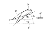
- FIG. 3 shows the inner fin 24 and the outer fin 25 as viewed from the port side.
- the inner fins 24 and the outer fins 25 are arranged with the wing-shaped ventral side down and the dorsal side up.
- the inner fin 24 is disposed with an installation angle ⁇ i with respect to the reference plane P1 including the rotation axis L1 (see FIG. 2).
- the outer fins 25 are arranged with an installation angle ⁇ o with respect to the reference plane P2 including the rotation axis L1 (see FIG. 2). Then, on the port side, the relationship between these installation angles ⁇ i and ⁇ o is as follows. ⁇ i> ⁇ o (1)
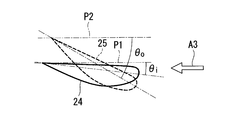
- FIG. 4 shows the inner fin 24 and the outer fin 25 as viewed from the starboard side.
- the inner fins 24 and the outer fins 25 are arranged with the wing-shaped belly side up and the back side down.
- the inner fin 24 is disposed with an installation angle ⁇ i with respect to the reference plane P1 including the rotation axis L1 (see FIG. 2).
- the outer fins 25 are arranged with an installation angle ⁇ o with respect to the reference plane P2 including the rotation axis L1 (see FIG. 2).
- the relationship between these installation angles ⁇ i and ⁇ o is expressed by the following equation. ⁇ i ⁇ o (2)
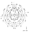
- the upstream side of the propeller 10 becomes a complicated flow field as shown in FIG. 5 due to the shape of the boshing 11 and the upstream side and the surrounding hull shape reaching the boshing 11.
- This figure shows the flow field on the upstream side of the propeller 10 as seen from the rear of the ship as in FIG.
- a horizontal line H and a vertical line V passing through the rotation axis L1 are shown.
- a solid line drawn like a contour line shows an isovelocity line in the direction of the rotation axis L1 (perpendicular to the paper surface), and the flow velocity is smaller on the inner circumference side closer to the rotation axis L1 and higher on the outer circumference side.
- a plurality of arrows indicate the flow direction of the water flow in a plane orthogonal to the rotation axis L1 (in the yz plane).
- the flow from the upper side to the lower side is mainly on the inner peripheral side around the rotation axis L1, and the flow from the lower side to the upper side is mainly along the circumferential direction on the outer peripheral side.
- the region indicated by reference sign S1 is located below the rotation axis L1 and on the outer peripheral side, and is a region where the flow velocity in the direction of the rotation axis L1 is large due to the influence of the flow outside the hull.
- the installation angle ⁇ i of the inner fin 24 and the installation angle ⁇ o of the outer fin 25 is ⁇ i> ⁇ o on the port side.
- the reason is as follows.
- the flow field on the inner peripheral side is mainly the flow from the upper side to the lower side, and is in the direction facing the propeller 10 that rotates from the lower side to the upper side. .
- the installation angle ⁇ i of the inner fin 24 is increased so as to promote the flow from the upper side to the lower side.
- the installation angle ⁇ i is set to be an angle of attack along the inflowing flow. In this case, the angle of attack is set to, for example, 0 ° to 20 ° C., preferably 0 ° to 15 °.
- the flow field on the outer peripheral side is mainly from the bottom to the top, and is in the same direction as the propeller 10 that rotates from the bottom to the top.
- the outer fins 25 have an installation angle that changes the flow downward.
- the installation angle ⁇ o of the outer fin 25 is set smaller than the installation angle ⁇ i of the inner fin 24.
- the inner fin 24 and the outer fin 25 were installed with the wing-shaped ventral side facing downward. Thereby, the flow direction can be effectively changed from the upper side to the lower side using the ventral shape, and the flow field can be further improved.
- the flow field on the inner peripheral side mainly flows from the upper side to the lower side, and is in the same direction as the propeller 10 that rotates from the upper side to the lower side. For this reason, the installation angle ⁇ i is increased so that the inner fin 24 changes the flow upward.
- the flow field on the outer peripheral side is mainly a flow from the lower side to the upper side, and is in a direction facing the propeller 10 rotating from the lower side to the upper side.
- the installation angle ⁇ o of the outer fin 25 is increased so as to promote the flow from the lower side to the upper side.
- the installation angle ⁇ o is set to be an angle of attack along the inflowing flow.
- the angle of attack is set to, for example, 0 ° to 20 ° C., preferably 0 ° to 15 °. From the above, as shown in Expression (2), the installation angle ⁇ o of the outer fin 25 is set larger than the installation angle ⁇ i of the inner fin 24.
- the inner fin 24 and the outer fin 25 were installed with the wing-shaped ventral side facing upward. Thereby, the flow direction can be effectively changed from the lower side to the upper side using the ventral shape, and the flow field can be further improved.
- this embodiment demonstrated on the assumption of the propeller clockwise, this embodiment is applicable also in the case of a propeller counterclockwise. Specifically, what is on the starboard side when the propeller is clockwise corresponds to the starboard side when the propeller is counterclockwise, and what is on the starboard side when the propeller is clockwise corresponds to the port side on the left side of the propeller . The same applies to the following embodiments.
- a corresponding outer fin 25b is provided at a position B1 shifted upward from the extending direction of the inner fin 24b in the middle stage of the port side. That is, the inner end of the outer fin 25 b is fixed to the duct 22 above the position where the outer end of the corresponding inner fin 24 b is fixed to the duct 22. This is because a larger flow velocity in the direction of the rotation axis L1 can be avoided in the upper region, and the effect of improving the flow field by providing the outer fins 25b in this region is greater.
- corresponding outer fins 25c and 25f are provided in the extending direction of the upper inner fin 24c on the port side and the inner fin 24f on the upper side of the starboard. This arrangement is the same as in the first embodiment.
- the installation angles ⁇ i and ⁇ o of the fins 24 and 25 are determined according to the flow field, as in the first embodiment.
- the number of the outer fins 25 is smaller than the number of the inner fins 24, and the number of the respective fins is different.
- the inner fins 24 and the outer fins 25 are positioned appropriately at the inner peripheral side and the outer peripheral side, which have different flow fields. Can be installed. Thereby, the flow field upstream of the propeller is improved on the inner peripheral side and the outer peripheral side, and the propulsion performance can be improved.
- the extending direction in the radial direction of the middle outer fin 25b on the port side and the outer fin 25c on the upper side of the port side is longer than the extending direction in the radial direction of the corresponding inner fins 24b and 24c. It faces upwards.
- the outer fin 25b on the middle side of the port side is fixed to the duct 22 at a position B1 above the extending direction of the corresponding inner fin 24b, and above the horizontal line H that is the extending direction of the corresponding inner fin 24b. It is arranged to face.
- the outer fin 25c at the upper end of the port side is fixed at the same circumferential position as the position where the corresponding inner fin 24c is fixed to the duct 22, while the fixed position with respect to the duct 22 is used as a boundary to the inner fin 24c. On the other hand, it is arranged in a state bent upward.
- the starboard outer fins 25e and 25f are provided in the same extending direction as the corresponding inner fins 243 and 24f, as in the first embodiment.
- the following operational effects can be obtained. Since the extending direction of the outer fins 25b and 25c is directed upward from the extending direction of the corresponding inner fins 24b and 24c, the flow is directed in a direction opposite to the propeller 10 that rotates upward from below on the port side. Can be changed. Thereby, the propeller efficiency can be improved by further improving the flow field above the port side.
- the upper side on the port side means a region above the horizontal line H passing through the rotation axis L1.
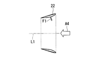
- FIG. 8 shows a longitudinal sectional view of the duct 22.
- the longitudinal section of the duct 22 has a wing shape.
- the cord length direction is provided so as to incline from the upstream side toward the downstream side toward the rotation axis L1. That is, the opening on the downstream side is smaller than the opening on the upstream side of the duct 22.
- the wing-shaped belly side is provided so as to face the inner peripheral side (rotation axis L1 side).
- the duct 22 has a wing-shaped longitudinal section in which the cord length direction is inclined so as to be inclined toward the rotation axis L1 from the upstream side toward the downstream side, the propulsive force is generated by the flow flowing into the duct 22. Obtainable. That is, above the duct 22, the water flow that flows into the inner peripheral side of the duct 22 generates lift F ⁇ b> 1 on the flank side of the wing shape. The component force of the rotational axis L1 of the lift force F1 becomes a propulsive force.
- the cord length below the duct 22 is smaller than the cord length above the duct 22. That is, the opening position on the downstream side of the duct 22 coincides with the upper and lower sides of the duct 22 in the direction of the rotation axis L1, but the opening position on the upstream side of the duct 22 is lower than the upper side of the duct 22. It is located on the downstream side.
- the flow field on the inner peripheral side is directed downward, so that even the wing-shaped duct 22 may cause separation of the flow and obtain a propulsive force. It's hard to be done. Therefore, the cord length below the duct 22 is made shorter than the upper one so as not to become more resistant. Note that the installation angle below the duct 22 may be set different from that above the duct 22 so that the installation angle is less resistant.
- a duct missing portion 22 a in which the duct 22 is partially missing is provided below the duct 22. That is, the duct 22 does not exist between the lower inner fins 24a and 24d. Therefore, the cross-sectional shape of the duct 22 is a C shape having an opening below.
- a partially missing duct portion 22 a is provided below the duct 22 to form a region where the duct 22 is not provided. Thereby, the resistance of the duct 22 in the region where the flow separation and the flow velocity in the direction of the rotation axis L1 are large can be reduced.
- this embodiment can be combined with each embodiment mentioned above.
- FIG. 11 is a diagram showing the duct 22 superimposed on the flow field shown in FIG.
- the duct center C1 is located at a position different from the rotation axis L1, and is provided above the rotation axis L1.
- the cross-sectional shape of the duct 22 is an elliptical shape having a long axis that coincides with the vertical line V.
- the duct center C1 is an elliptical centroid.
- the upper half of the duct 22 is installed in a region that flows from above toward the duct center C1. Thereby, a thrust can be more effectively generated in the duct 22.
- the lower half of the duct 22 has a long axis of the ellipse directed in the direction of the vertical line V, and the right and left walls in FIG. Yes. Further, by directing the short axis of the ellipse in the direction of the horizontal line H, the region of the lower end portion of the duct 22 is shortened to reduce the resistance.
- FIG. 12 shows a modification of FIG.
- the duct center C1 is provided below the rotation axis L1.
- the elliptical shape of the cross section of the duct 22 is provided with a short axis corresponding to the vertical line V, and a long axis is provided along the horizontal line H direction.
- the upper half of the duct 22 is installed in a region that flows from above toward the duct center C1. Thereby, a thrust can be more effectively generated in the duct 22.
- the lower half of the duct 22 is provided so that the water flow is deflected in the left-right direction (horizontal direction) from the downward flow and coincides with the upward flow. Thereby, the resistance of the duct 22 can be reduced.
- the cross-sectional shape of the duct 22 is an ellipse.
- the shape is not limited to this, and a shape in which a plurality of curvatures are combined so as to be in an appropriate position according to the flow field. Also good.
- FIG. 13 shows another modification.
- the duct center C1 is located above and to the right of the rotation axis L1. This corresponds to the case where the flow field on the upstream side of the propeller 10 is shifted by a predetermined angle in the right direction indicated by the arrow A5 about the rotation axis L1 due to the influence of the rotation of the propeller 10. That is, the horizontal line of the flow field is shifted to the position indicated by the symbol H ′, and the vertical line is shifted to the position indicated by the symbol V ′.
- the duct 22 can be installed in an appropriate position according to the flow field.
- this embodiment can be combined with each embodiment mentioned above.
Landscapes
- Chemical & Material Sciences (AREA)
- Engineering & Computer Science (AREA)
- Combustion & Propulsion (AREA)
- Mechanical Engineering (AREA)
- Ocean & Marine Engineering (AREA)
- Structures Of Non-Positive Displacement Pumps (AREA)
Abstract
La présente invention comprend : un conduit (22) qui se situe devant une hélice d'un navire, et qui est fixé à un côté bossage (11) de manière à entourer l'axe de rotation (L1) de l'hélice ; des ailettes intérieures (24) qui ont des extrémités extérieures fixées au côté périphérique intérieur du conduit (22) et s'étendent radialement vers l'intérieur en direction de l'axe de rotation (L1) ; et des ailettes extérieures (25) qui se situent dans la direction d'extension des ailettes intérieures (24), et qui ont des extrémités intérieures fixées au côté périphérique extérieur du conduit (22) et s'étendent radialement vers l'extérieur. Si la rotation de l'hélice est dans le sens des aiguilles d'une montre telle que vue depuis l'arrière du navire, l'angle d'attaque par rapport à l'eau de pénétration est formé sur le côté orifice, et θi > θo est défini où θi est l'angle d'installation des ailettes intérieures (24) par rapport à un plan de référence comprenant l'axe de rotation (L1) et θo étant l'angle d'installation des ailettes extérieures (25) par rapport au plan de référence.
Applications Claiming Priority (2)
| Application Number | Priority Date | Filing Date | Title |
|---|---|---|---|
| JP2016238649A JP6689736B2 (ja) | 2016-12-08 | 2016-12-08 | フィンユニット装置およびこれを備えた船舶 |
| JP2016-238649 | 2016-12-08 |
Publications (1)
| Publication Number | Publication Date |
|---|---|
| WO2018105451A1 true WO2018105451A1 (fr) | 2018-06-14 |
Family
ID=62491897
Family Applications (1)
| Application Number | Title | Priority Date | Filing Date |
|---|---|---|---|
| PCT/JP2017/042710 Ceased WO2018105451A1 (fr) | 2016-12-08 | 2017-11-29 | Dispositif d'unité d'ailette et navire équipé de celui-ci |
Country Status (3)
| Country | Link |
|---|---|
| JP (1) | JP6689736B2 (fr) |
| KR (1) | KR102143323B1 (fr) |
| WO (1) | WO2018105451A1 (fr) |
Families Citing this family (1)
| Publication number | Priority date | Publication date | Assignee | Title |
|---|---|---|---|---|
| JP7296107B2 (ja) * | 2019-06-28 | 2023-06-22 | 国立研究開発法人 海上・港湾・航空技術研究所 | 船尾用付加物、船尾用付加物を有した船尾形状、及び船舶 |
Citations (7)
| Publication number | Priority date | Publication date | Assignee | Title |
|---|---|---|---|---|
| JPS537096A (en) * | 1976-07-06 | 1978-01-23 | Mitsui Eng & Shipbuild Co Ltd | Ship |
| JPH07267189A (ja) * | 1994-03-31 | 1995-10-17 | Mitsubishi Heavy Ind Ltd | 整流フィン付き舶用プロペラ装置 |
| KR20120124205A (ko) * | 2011-05-03 | 2012-11-13 | 에스피피조선 주식회사 | 연료절감형 선박용 크라운 덕트 |
| KR101453210B1 (ko) * | 2013-09-23 | 2014-10-22 | 한국해양과학기술원 | 익형 단면을 가지는 선미 장착 덕트 |
| KR20150145333A (ko) * | 2014-06-18 | 2015-12-30 | 현대중공업 주식회사 | 선박용 추진장치 |
| JP2016175635A (ja) * | 2015-03-06 | 2016-10-06 | ベッカー マリン システムズ ゲーエムベーハー ウント コー カーゲーbecker marine systems GmbH&Co.KG | 船外プロペラシャフトを備える多軸船のための配置構成、及び、該配置構成の製造方法 |
| KR101764400B1 (ko) * | 2016-11-24 | 2017-08-10 | 재단법인한국조선해양기자재연구원 | 추진효율 향상을 위한 트위스트 타입 스테이터를 구비한 선박용 덕트장치 |
Family Cites Families (3)
| Publication number | Priority date | Publication date | Assignee | Title |
|---|---|---|---|---|
| JPS591512B2 (ja) | 1980-06-05 | 1984-01-12 | 株式会社神戸製鋼所 | 溶接用フラツクス入りワイヤ |
| JP5281559B2 (ja) | 2009-12-14 | 2013-09-04 | 三菱重工業株式会社 | 船舶の推進性能向上装置 |
| PT2591994E (pt) | 2011-11-11 | 2014-09-18 | Becker Marine Sys Gmbh & Co Kg | Dispositivo para redução do consumo de combustível da propulsão de uma embarcação |
-
2016
- 2016-12-08 JP JP2016238649A patent/JP6689736B2/ja not_active Expired - Fee Related
-
2017
- 2017-11-29 KR KR1020187033092A patent/KR102143323B1/ko not_active Expired - Fee Related
- 2017-11-29 WO PCT/JP2017/042710 patent/WO2018105451A1/fr not_active Ceased
Patent Citations (7)
| Publication number | Priority date | Publication date | Assignee | Title |
|---|---|---|---|---|
| JPS537096A (en) * | 1976-07-06 | 1978-01-23 | Mitsui Eng & Shipbuild Co Ltd | Ship |
| JPH07267189A (ja) * | 1994-03-31 | 1995-10-17 | Mitsubishi Heavy Ind Ltd | 整流フィン付き舶用プロペラ装置 |
| KR20120124205A (ko) * | 2011-05-03 | 2012-11-13 | 에스피피조선 주식회사 | 연료절감형 선박용 크라운 덕트 |
| KR101453210B1 (ko) * | 2013-09-23 | 2014-10-22 | 한국해양과학기술원 | 익형 단면을 가지는 선미 장착 덕트 |
| KR20150145333A (ko) * | 2014-06-18 | 2015-12-30 | 현대중공업 주식회사 | 선박용 추진장치 |
| JP2016175635A (ja) * | 2015-03-06 | 2016-10-06 | ベッカー マリン システムズ ゲーエムベーハー ウント コー カーゲーbecker marine systems GmbH&Co.KG | 船外プロペラシャフトを備える多軸船のための配置構成、及び、該配置構成の製造方法 |
| KR101764400B1 (ko) * | 2016-11-24 | 2017-08-10 | 재단법인한국조선해양기자재연구원 | 추진효율 향상을 위한 트위스트 타입 스테이터를 구비한 선박용 덕트장치 |
Also Published As
| Publication number | Publication date |
|---|---|
| JP6689736B2 (ja) | 2020-04-28 |
| JP2018094959A (ja) | 2018-06-21 |
| KR102143323B1 (ko) | 2020-08-11 |
| KR20180134997A (ko) | 2018-12-19 |
| KR102143323B9 (ko) | 2022-02-14 |
Similar Documents
| Publication | Publication Date | Title |
|---|---|---|
| TWI498253B (zh) | 改善能源效率之船舶驅動系統的前置導管 | |
| JP5230852B1 (ja) | 小型ダクト付きプロペラ及び船舶 | |
| JP2011178222A (ja) | 船舶 | |
| JP6422020B2 (ja) | ツインスケグ船 | |
| WO2016158725A1 (fr) | Vaisseau | |
| KR101516842B1 (ko) | 선박용 덕트 구조체 | |
| KR102531811B1 (ko) | 선미 덕트를 가진 선미 형상 및 선박 | |
| WO2018105451A1 (fr) | Dispositif d'unité d'ailette et navire équipé de celui-ci | |
| JP6138680B2 (ja) | ダクト装置 | |
| JP5901512B2 (ja) | ダクト装置及びそれを用いた船舶 | |
| JP2011042204A (ja) | 舶用複合型省エネ推進装置及び一軸二舵船舶 | |
| JP5510798B2 (ja) | 船舶用推進性能向上装置 | |
| JP6021678B2 (ja) | ダクト装置及びそれを用いた船舶 | |
| JP5388184B2 (ja) | ポッド推進器 | |
| WO2016080002A1 (fr) | Dispositif de propulsion pour bateau à deux vis voisines ayant des supports d'arbre, et navire | |
| WO2018025644A1 (fr) | Navire | |
| JP6704303B2 (ja) | リアクションフィン装置 | |
| KR20120068222A (ko) | 선박용 덕트 구조체 | |
| JP6239711B1 (ja) | 船舶のダクト装置 | |
| JP2014151876A (ja) | 船舶用リアクションフィン装置 | |
| JP6380848B2 (ja) | 船舶 | |
| JP2004114743A (ja) | 船舶 | |
| JP2014156200A (ja) | フィン装置及び船舶 | |
| JP2011098702A (ja) | 推進装置及びそれを用いた船舶 |
Legal Events
| Date | Code | Title | Description |
|---|---|---|---|
| ENP | Entry into the national phase |
Ref document number: 20187033092 Country of ref document: KR Kind code of ref document: A |
|
| 121 | Ep: the epo has been informed by wipo that ep was designated in this application |
Ref document number: 17879524 Country of ref document: EP Kind code of ref document: A1 |
|
| NENP | Non-entry into the national phase |
Ref country code: DE |
|
| 122 | Ep: pct application non-entry in european phase |
Ref document number: 17879524 Country of ref document: EP Kind code of ref document: A1 |