WO2018109894A1 - Dispositif à cycle de réfrigération - Google Patents
Dispositif à cycle de réfrigération Download PDFInfo
- Publication number
- WO2018109894A1 WO2018109894A1 PCT/JP2016/087366 JP2016087366W WO2018109894A1 WO 2018109894 A1 WO2018109894 A1 WO 2018109894A1 JP 2016087366 W JP2016087366 W JP 2016087366W WO 2018109894 A1 WO2018109894 A1 WO 2018109894A1
- Authority
- WO
- WIPO (PCT)
- Prior art keywords
- refrigerant
- compressor
- condenser
- refrigeration cycle
- pump
- Prior art date
- Legal status (The legal status is an assumption and is not a legal conclusion. Google has not performed a legal analysis and makes no representation as to the accuracy of the status listed.)
- Ceased
Links
Images







Classifications
-
- F—MECHANICAL ENGINEERING; LIGHTING; HEATING; WEAPONS; BLASTING
- F25—REFRIGERATION OR COOLING; COMBINED HEATING AND REFRIGERATION SYSTEMS; HEAT PUMP SYSTEMS; MANUFACTURE OR STORAGE OF ICE; LIQUEFACTION SOLIDIFICATION OF GASES
- F25B—REFRIGERATION MACHINES, PLANTS OR SYSTEMS; COMBINED HEATING AND REFRIGERATION SYSTEMS; HEAT PUMP SYSTEMS
- F25B1/00—Compression machines, plants or systems with non-reversible cycle
-
- F—MECHANICAL ENGINEERING; LIGHTING; HEATING; WEAPONS; BLASTING
- F25—REFRIGERATION OR COOLING; COMBINED HEATING AND REFRIGERATION SYSTEMS; HEAT PUMP SYSTEMS; MANUFACTURE OR STORAGE OF ICE; LIQUEFACTION SOLIDIFICATION OF GASES
- F25B—REFRIGERATION MACHINES, PLANTS OR SYSTEMS; COMBINED HEATING AND REFRIGERATION SYSTEMS; HEAT PUMP SYSTEMS
- F25B13/00—Compression machines, plants or systems, with reversible cycle
-
- F—MECHANICAL ENGINEERING; LIGHTING; HEATING; WEAPONS; BLASTING
- F25—REFRIGERATION OR COOLING; COMBINED HEATING AND REFRIGERATION SYSTEMS; HEAT PUMP SYSTEMS; MANUFACTURE OR STORAGE OF ICE; LIQUEFACTION SOLIDIFICATION OF GASES
- F25B—REFRIGERATION MACHINES, PLANTS OR SYSTEMS; COMBINED HEATING AND REFRIGERATION SYSTEMS; HEAT PUMP SYSTEMS
- F25B41/00—Fluid-circulation arrangements
-
- F—MECHANICAL ENGINEERING; LIGHTING; HEATING; WEAPONS; BLASTING
- F25—REFRIGERATION OR COOLING; COMBINED HEATING AND REFRIGERATION SYSTEMS; HEAT PUMP SYSTEMS; MANUFACTURE OR STORAGE OF ICE; LIQUEFACTION SOLIDIFICATION OF GASES
- F25B—REFRIGERATION MACHINES, PLANTS OR SYSTEMS; COMBINED HEATING AND REFRIGERATION SYSTEMS; HEAT PUMP SYSTEMS
- F25B41/00—Fluid-circulation arrangements
- F25B41/20—Disposition of valves, e.g. of on-off valves or flow control valves
-
- F—MECHANICAL ENGINEERING; LIGHTING; HEATING; WEAPONS; BLASTING
- F25—REFRIGERATION OR COOLING; COMBINED HEATING AND REFRIGERATION SYSTEMS; HEAT PUMP SYSTEMS; MANUFACTURE OR STORAGE OF ICE; LIQUEFACTION SOLIDIFICATION OF GASES
- F25B—REFRIGERATION MACHINES, PLANTS OR SYSTEMS; COMBINED HEATING AND REFRIGERATION SYSTEMS; HEAT PUMP SYSTEMS
- F25B49/00—Arrangement or mounting of control or safety devices
- F25B49/02—Arrangement or mounting of control or safety devices for compression type machines, plants or systems
-
- F—MECHANICAL ENGINEERING; LIGHTING; HEATING; WEAPONS; BLASTING
- F25—REFRIGERATION OR COOLING; COMBINED HEATING AND REFRIGERATION SYSTEMS; HEAT PUMP SYSTEMS; MANUFACTURE OR STORAGE OF ICE; LIQUEFACTION SOLIDIFICATION OF GASES
- F25B—REFRIGERATION MACHINES, PLANTS OR SYSTEMS; COMBINED HEATING AND REFRIGERATION SYSTEMS; HEAT PUMP SYSTEMS
- F25B49/00—Arrangement or mounting of control or safety devices
- F25B49/02—Arrangement or mounting of control or safety devices for compression type machines, plants or systems
- F25B49/022—Compressor control arrangements
-
- F—MECHANICAL ENGINEERING; LIGHTING; HEATING; WEAPONS; BLASTING
- F25—REFRIGERATION OR COOLING; COMBINED HEATING AND REFRIGERATION SYSTEMS; HEAT PUMP SYSTEMS; MANUFACTURE OR STORAGE OF ICE; LIQUEFACTION SOLIDIFICATION OF GASES
- F25B—REFRIGERATION MACHINES, PLANTS OR SYSTEMS; COMBINED HEATING AND REFRIGERATION SYSTEMS; HEAT PUMP SYSTEMS
- F25B2600/00—Control issues
- F25B2600/02—Compressor control
- F25B2600/025—Compressor control by controlling speed
- F25B2600/0253—Compressor control by controlling speed with variable speed
-
- F—MECHANICAL ENGINEERING; LIGHTING; HEATING; WEAPONS; BLASTING
- F25—REFRIGERATION OR COOLING; COMBINED HEATING AND REFRIGERATION SYSTEMS; HEAT PUMP SYSTEMS; MANUFACTURE OR STORAGE OF ICE; LIQUEFACTION SOLIDIFICATION OF GASES
- F25B—REFRIGERATION MACHINES, PLANTS OR SYSTEMS; COMBINED HEATING AND REFRIGERATION SYSTEMS; HEAT PUMP SYSTEMS
- F25B2600/00—Control issues
- F25B2600/25—Control of valves
- F25B2600/2501—Bypass valves
-
- Y—GENERAL TAGGING OF NEW TECHNOLOGICAL DEVELOPMENTS; GENERAL TAGGING OF CROSS-SECTIONAL TECHNOLOGIES SPANNING OVER SEVERAL SECTIONS OF THE IPC; TECHNICAL SUBJECTS COVERED BY FORMER USPC CROSS-REFERENCE ART COLLECTIONS [XRACs] AND DIGESTS
- Y02—TECHNOLOGIES OR APPLICATIONS FOR MITIGATION OR ADAPTATION AGAINST CLIMATE CHANGE
- Y02B—CLIMATE CHANGE MITIGATION TECHNOLOGIES RELATED TO BUILDINGS, e.g. HOUSING, HOUSE APPLIANCES OR RELATED END-USER APPLICATIONS
- Y02B30/00—Energy efficient heating, ventilation or air conditioning [HVAC]
- Y02B30/70—Efficient control or regulation technologies, e.g. for control of refrigerant flow, motor or heating
Definitions
- the present invention relates to a refrigeration cycle apparatus that performs a low outside air cooling operation.
- the cooling operation by the refrigeration cycle apparatus may be continuously performed for a certain period regardless of the outside air temperature. For example, in a server room where the server computer is operating almost all year long, if the temperature rise in the server room due to the heat generated from the server computer is left unattended, the processing capacity of the server computer will drop and the server computer will fail and stop. It is also envisaged. In order to prevent such a situation, the cooling operation by the refrigeration cycle apparatus is usually performed throughout the year in the server room.
- the indoor temperature is usually higher than the outdoor temperature, and thus the temperature difference between the indoor temperature and the outdoor temperature.
- a reference temperature for example, 7 ° C.
- the indoor temperature is usually higher than the outdoor temperature, and thus the temperature difference between the indoor temperature and the outdoor temperature.
- the liquid from the outdoor condenser is used instead of the refrigeration cycle (vapor compression cycle) by the compressor.
- a refrigeration cycle liquid pump cycle
- the liquid pump cycle can suppress power consumption more than the vapor compression cycle.
- the amount of liquid refrigerant required in the liquid pump cycle is larger than the amount of liquid refrigerant required in the vapor compression cycle by the amount that the liquid refrigerant is compressed by the liquid pump.
- the amount of the liquid refrigerant is insufficient, the refrigerant sucked into the liquid pump becomes wet vapor in a gas-liquid two-phase state, and the possibility that cavitation occurs in the liquid pump increases.
- Cavitation is a phenomenon in which gas refrigerant is generated in the refrigerant. If cavitation occurs in the liquid pump, the liquid pump may break down and it may be difficult to continue the low outside air cooling operation.
- the present invention has been made to solve the above-described problems, and an object thereof is to improve the stability of the low outside air cooling operation.
- the refrigeration cycle apparatus performs cooling by circulating the refrigerant.
- the refrigeration cycle apparatus includes an evaporator, a condenser, a pump, a compressor, and a control device.
- the evaporator is disposed in the first space.
- the condenser is disposed in the second space.
- the pump is configured to compress the refrigerant from the condenser and output it to the evaporator.
- the compressor is configured to compress the refrigerant from the evaporator and output it to the condenser.
- the control device is configured to cool the first space by controlling the pump and the compressor.
- the control device is configured to start the pump after starting the compressor in a state where the temperature of the first space is higher than the temperature of the second space.
- the pump that performs the liquid pump cycle is started after the compressor is started.
- the generation rate of the liquid refrigerant in the condenser is increased, and the amount of liquid refrigerant from the condenser is increased.
- the occurrence of cavitation in the pump can be suppressed, and the stability of the low outside air cooling operation can be improved.
- FIG. 2 is a functional block diagram showing a configuration of a refrigeration cycle apparatus according to Embodiment 1.
- FIG. It is a figure which shows together the time chart of the frequency of the liquid pump in Embodiment 1, and the time chart of the frequency of a compressor.
- FIG. 3 is a Ph diagram showing a relationship between refrigerant pressure and enthalpy during a period in which the liquid pump is stopped and the vapor compression cycle is performed in FIG.
- FIG. 3 is a Ph diagram illustrating a relationship between refrigerant pressure and enthalpy during a period in which both the vapor compression cycle and the liquid pump cycle are performed in FIG. 2.
- FIG. 3 is a Ph diagram showing a relationship between refrigerant pressure and enthalpy during a period in which both the vapor compression cycle and the liquid pump cycle are performed in FIG. 2.
- FIG. 3 is a Ph diagram illustrating a relationship between refrigerant pressure and enthalpy during a period in which the compressor is stopped and the liquid pump cycle is performed in FIG. 2.
- 6 is a functional block diagram showing a configuration of a refrigeration cycle apparatus according to Embodiment 2.
- FIG. It is a figure which shows together the time chart of the frequency of the liquid pump in Embodiment 2, the time chart of the frequency of a compressor, and the time chart of the opening degree of an expansion valve.
- FIG. 8 is a Ph diagram showing the relationship between the refrigerant pressure and enthalpy during the period when the liquid pump is stopped and the vapor compression cycle is performed in FIG. 7.
- FIG. 7 is a Ph diagram illustrating a relationship between refrigerant pressure and enthalpy during a period in which the compressor is stopped and the liquid pump cycle is performed in FIG. 7.
- FIG. 8 is a Ph diagram showing a relationship between refrigerant pressure and enthalpy during a period in which both the vapor compression cycle and the liquid pump cycle are performed in FIG. 7.
- FIG. 8 is a Ph diagram illustrating the relationship between the refrigerant pressure and enthalpy during the period when the compressor is stopped and the liquid pump cycle is performed in FIG. 7.
- 6 is a functional block diagram showing a configuration of a refrigeration cycle apparatus according to Embodiment 3.
- FIG. It is a figure which shows together the time chart of the frequency of the liquid pump in Embodiment 3, the time chart of the frequency of a compressor, and the time chart of the opening degree of an expansion valve.
- FIG. 13 is a Ph diagram showing the relationship between the refrigerant pressure and enthalpy during the period when the liquid pump is stopped and the vapor compression cycle is performed in FIG.
- FIG. 13 is a Ph diagram showing a relationship between refrigerant pressure and enthalpy during a period in which both the vapor compression cycle and the liquid pump cycle are performed in FIG.
- FIG. 13 is a Ph diagram showing the relationship between the refrigerant pressure and enthalpy during the period when the compressor is stopped and the liquid pump cycle is performed in FIG.
- FIG. 10 is a functional block diagram illustrating a configuration of a refrigeration cycle apparatus according to a modification of the third embodiment.
- FIG. 1 is a functional block diagram showing the configuration of the refrigeration cycle apparatus 100 according to the first embodiment.
- the refrigeration cycle apparatus 100 includes an indoor unit 10 disposed indoors and an outdoor unit 20 disposed outdoor.
- the refrigeration cycle apparatus 100 performs a low outside air cooling operation.
- the indoor unit 10 includes a compressor 1, an evaporator 3, an indoor fan 5, and a bypass channel 11.
- the outdoor unit 20 includes a condenser 2, an outdoor fan 4, a liquid pump 6, a control device 30, and a temperature sensor 40.
- the control device 30 may be included in the indoor unit 10 or may not be included in either the indoor unit 10 or the outdoor unit 20.
- the liquid pump 6 compresses the liquid refrigerant (liquid refrigerant) from the condenser 2 and outputs it to the evaporator 3.
- the driving frequency of the liquid pump 6 is controlled by the control device 30 to control the amount of refrigerant discharged per unit time.
- the evaporator 3 evaporates the liquid refrigerant from the liquid pump 6.
- the liquid refrigerant takes heat (evaporation heat) from the indoor air and evaporates to become a gaseous refrigerant (gas refrigerant) and flows out of the evaporator 3.
- the compressor 1 compresses the gas refrigerant from the evaporator 3 and outputs it to the condenser 2.
- the drive frequency of the compressor 1 is controlled by the control device 30 to control the amount of refrigerant discharged per unit time.
- the bypass channel 11 connects the channel between the evaporator 3 and the compressor 1 and the channel between the compressor 1 and the condenser 2.
- the bypass channel 11 is connected in parallel to the compressor 1 between the evaporator 3 and the condenser 2.
- the bypass flow path 11 includes a check valve 7. The check valve 7 is used when the refrigerant pressure in the flow path between the evaporator 3 and the compressor 1 is higher than the refrigerant pressure in the flow path between the compressor 1 and the condenser 2. Pass through.
- the outdoor fan 4 blows air to the condenser 2 in order to promote heat exchange between the refrigerant and the air in the condenser 2.
- the rotation speed of the outdoor fan 4 is controlled by the control device 30 to control the amount of air blown per unit time.
- the indoor fan 5 sends air to the evaporator 3 in order to promote heat exchange between the refrigerant and the air in the evaporator 3.
- the rotation speed of the indoor fan 5 is controlled by the control device 30, and the amount of air blown per unit time is controlled.
- the temperature sensor 40 measures the temperature of the refrigerant between the condenser 2 and the liquid pump 6.
- the temperature sensor 40 is, for example, a thermistor.
- Control device 30 controls compressor 1, liquid pump 6, outdoor fan 4, and indoor fan 5.
- the control device 30 receives a signal from the temperature sensor 40 and calculates the degree of supercooling of the refrigerant from the condenser 2.
- the amount of liquid refrigerant required in the liquid pump cycle is insufficient, the refrigerant sucked into the liquid pump 6 becomes wet vapor in a gas-liquid two-phase state, and the possibility that cavitation occurs in the liquid pump 6 increases. If cavitation occurs in the liquid pump 6, the liquid pump 6 may break down, and it may be difficult to continue the low outside air cooling operation.
- the liquid pump 6 is started after the vapor compression cycle by the compressor 1 is performed for a certain time.
- the vapor compression cycle by the compressor 1 is performed to increase the generation rate of the liquid refrigerant and increase the amount of the liquid refrigerant from the condenser 2.
- the occurrence of cavitation in the liquid pump 6 is suppressed, and the stability of the low outside air cooling operation can be improved.
- FIG. 2 is a diagram showing a time chart of the frequency of the liquid pump 6 and a time chart of the frequency of the compressor 1 in the first embodiment.
- the compressor 1 is started at time tm1, and a vapor compression cycle is performed in a period S1 between times tm1 and tm2.
- the liquid pump 6 is stopped because the amount of refrigerant from the condenser 2 is insufficient and cavitation is likely to occur.
- the liquid pump 6 starts at time tm2.
- the frequency of the liquid pump 6 increases with time and the frequency of the compressor 1 decreases with time.
- the liquid pump cycle and the vapor compression cycle are performed simultaneously.
- a period S3 after time tm3, the compressor 1 is stopped and a liquid pump cycle by the liquid pump 6 is performed.
- FIG. 3 is a Ph diagram (Mollier diagram) showing the relationship between the refrigerant pressure and enthalpy in the period S1 of FIG. In the period S1, the vapor compression cycle by the compressor 1 is performed, while the liquid pump 6 is stopped.
- curves IS1 and IS2 are refrigerant isotherms corresponding to the outside air temperature T1 and the indoor temperature T2 (T1> T2), respectively.
- Curve LC is a saturated liquid line of the refrigerant.
- a curve GC is a saturated vapor line of the refrigerant.
- Point CP is the critical point of the refrigerant.
- the critical point is a point indicating a limit of a range in which a phase change can occur between the liquid refrigerant and the gas refrigerant, and is an intersection of the saturated liquid line and the saturated vapor line.
- the refrigerant pressure becomes higher than the pressure at the critical point, no phase change occurs between the liquid refrigerant and the gas refrigerant.
- the refrigerant In the region where the enthalpy is lower than the saturated liquid line, the refrigerant is a liquid. In the region sandwiched between the saturated liquid line and the saturated vapor line, the refrigerant is wet steam. In the region where the enthalpy is higher than the saturated vapor line, the refrigerant is a gas.
- FIGS. 4 and 5 FIGS. 8 to 10 of the second embodiment, and FIGS. 13 to 15 of the third embodiment.
- Cycle C11 that circulates in order from point R11 to point R14 represents the circulation of the refrigerant in the period S1 in FIG. As shown in FIG. 3, cycle C11 is performed in a state where the room temperature is higher than the outside air temperature. The same applies to the cycles C12, C13, C21 to C23, and C31 to C33 shown in FIGS. 4, 5, FIGS. 8 to 10 of the second embodiment, and FIGS. 13 to 15 of the third embodiment. .
- the process of state change from the point R11 to the point R12 represents the refrigerant compression process by the compressor 1.
- the pressure and enthalpy of the refrigerant in the state of point R12 are both greater than the pressure and enthalpy of the refrigerant in the state of point R11 due to compression by the compressor 1.
- the process of state change from the point R12 to the point R13 represents the condensation process of the refrigerant by the condenser 2.
- the difference between the temperature of the refrigerant at the intersection R15 between the condensation process and the saturated liquid line LC and the temperature of the refrigerant at the end point R13 of the condensation process is the refrigerant subcooling degree SC at the point R13.
- the degree of supercooling SC is a value indicating how many times the temperature of the refrigerant has further decreased since the refrigerant has liquefied.
- the refrigerant in the state of point R13 is sucked into the liquid pump 6 when the liquid pump is activated.
- the state change process from the point R13 to the point R14 represents a process in which the refrigerant passes from the condenser 2 to the evaporator 3 through the liquid pump 6 stopped. Since pressure loss occurs when the refrigerant passes through the piping and the liquid pump 6 that is stopped, the pressure decreases in the process from the point R13 to the point R14.
- the process of the state change from the point R14 to the point R11 represents the evaporation process of the refrigerant by the evaporator 3.
- the generation rate of the liquid refrigerant in the condenser 2 increases, the amount of gas refrigerant in the condenser 2 decreases, and the amount of liquid refrigerant increases.
- the degree of supercooling SC of the refrigerant flowing out of the condenser 2 increases.
- the degree of supercooling SC of the refrigerant sucked into the liquid pump 6 increases, the state of the refrigerant moves away from the gas-liquid two-phase region, so that cavitation is less likely to occur in the liquid pump 6.
- the gas-liquid two-phase state of the refrigerant sucked into the liquid pump 6 is canceled and the refrigerant is The liquid pump 6 is started assuming that the liquid has been sufficiently liquefied.
- the reference value can be appropriately calculated through actual machine experiments or simulations.
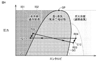
- FIG. 4 is a Ph diagram showing the relationship between the refrigerant pressure and enthalpy in the period S2 in FIG. In the period S2, the vapor compression cycle by the compressor 1 is continued and the liquid pump 6 is started.
- a cycle C12 that circulates in the order of points R21 to R24 represents the circulation of the refrigerant in the period S2 in FIG.
- the process of state change from the point R21 to the point R22 represents the refrigerant compression process by the liquid pump 6.
- the pressure and enthalpy of the refrigerant in the state of point R22 are both greater than the pressure and enthalpy of the refrigerant in the state of point R21 due to compression by the liquid pump 6.
- the process of state change from the point R22 to the point R23 represents the evaporation process of the refrigerant by the evaporator 3.
- the process of state change from the point R23 to the point R24 represents the refrigerant compression process by the compressor 1.
- the process of state change from the point R24 to the point R21 represents the process of condensing the refrigerant by the condenser 2.
- the control device 30 increases the frequency of the liquid pump 6 over time and gradually increases the amount of refrigerant sucked by the liquid pump 6.
- the control device 30 decreases the frequency of the compressor 1 with time and gradually decreases the amount of liquid refrigerant generated in the condenser 2.
- FIG. 5 is a Ph diagram showing the relationship between the refrigerant pressure and enthalpy in the period S3 in FIG.
- the compressor 1 is stopped, while the liquid pump cycle by the liquid pump 6 is continued.
- a cycle C13 that circulates in the order of the points R31 to R34 represents the circulation of the refrigerant in the period S3 in FIG.
- the process of state change from the point R31 to the point R32 represents the refrigerant compression process by the liquid pump 6.
- the process of state change from the point R32 to the point R33 represents the evaporation process of the refrigerant by the evaporator 3.
- the state change process from the point R33 to the point R34 represents a process in which the refrigerant passes from the evaporator 3 through the check valve 7 to the condenser 2.
- the pressure of the refrigerant in the flow path between the evaporator 3 and the compressor 1 is changed to that of the refrigerant in the flow path between the compressor 1 and the condenser 2. Higher than pressure.
- Most of the refrigerant enters the bypass passage 11 having a low pressure resistance, passes through the check valve 7 and bypasses the compressor 1. When most of the refrigerant passes through the bypass flow path 11 when the compressor is stopped, the refrigerant can be prevented from staying in the stopped compressor 1.
- the refrigerant in the state of the point R34 rather than the pressure of the refrigerant in the state of the point R33 due to pressure loss caused when the refrigerant passes through the pipe and the check valve.
- the pressure of is smaller.
- the process of state change from the point R34 to the point R31 represents the condensation process of the refrigerant by the condenser 2.
- the condition for starting the liquid pump 6 is that the supercooling degree SC exceeds the reference value.
- the condition for starting the liquid pump 6 may be any condition as long as it can be determined that the gas-liquid two-phase state of the refrigerant sucked into the liquid pump 6 is eliminated and the refrigerant is sufficiently liquefied.
- the condition that the operation of the compressor 1 continues for a reference time may be used.
- the bypass flow path 11 includes a check valve.
- the bypass flow path 11 does not necessarily include a check valve, and the pressure of the refrigerant in the flow path between the evaporator 3 and the compressor 1 flows between the compressor 1 and the condenser 2. Any configuration may be used as long as the refrigerant is allowed to pass when the pressure is higher than the pressure of the refrigerant in the passage.
- the bypass flow path 11 includes an on-off valve, and the pressure of the refrigerant in the flow path between the evaporator 3 and the compressor 1 is the pressure of the refrigerant in the flow path between the compressor 1 and the condenser 2. If higher, the control device 30 may control the open / close valve to open the open / close valve.
- the liquid pump that performs the liquid pump cycle is started after the compressor is started.
- the generation rate of the liquid refrigerant in the condenser is increased, and the amount of liquid refrigerant from the condenser is increased.
- the occurrence of cavitation in the liquid pump is suppressed, and the stability of the low outside air cooling operation can be improved.
- the refrigerant when the compressor is stopped, bypasses the compressor by passing through the bypass flow path, so that the refrigerant is prevented from staying in the stopped compressor. Can do.
- the control device activates the liquid pump when the degree of supercooling of the refrigerant sucked into the liquid pump is larger than the reference value, and therefore further suppresses the occurrence of cavitation in the liquid pump. Can do.
- the control device increases the amount of refrigerant discharged by the liquid pump per unit time with the passage of time after the liquid pump is started, and the refrigerant discharged by the compressor per unit time. By reducing the amount with the passage of time after starting the liquid pump, it is possible to further suppress the occurrence of cavitation in the liquid pump.
- the heat exchange in the evaporator is promoted by the indoor fan, and the heat exchange in the condenser is promoted by the outdoor fan. Therefore, the production rate of the liquid refrigerant in the condenser in the vapor compression cycle is increased. To rise. As a result, the start of the liquid pump cycle can be accelerated.
- Embodiment 2 a case where the refrigerant from the liquid pump flows into the evaporator via the pressure regulating valve will be described.
- the difference between the second embodiment and the first embodiment is that a pressure regulating valve is connected between the liquid pump and the evaporator. Since the other points are the same, the description will not be repeated.
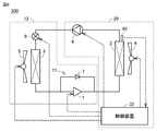
- FIG. 6 is a functional block diagram showing the configuration of the refrigeration cycle apparatus 200 according to the second embodiment.
- the indoor unit 10 and the control device 30 in FIG. 1 are replaced with the indoor unit 12 and the control device 32, respectively.
- the indoor unit 12 includes an expansion valve 8 as a pressure adjustment valve in addition to the configuration included in the indoor unit 10 shown in FIG. 1.
- the expansion valve 8 is connected between the liquid pump 6 and the evaporator 3. The opening degree of the expansion valve 8 is adjusted by the control device 32.
- the expansion valve 8 is, for example, an electronically controlled expansion valve (LEV: Linear Expansion Valve).
- FIG. 7 is a diagram showing a time chart of the frequency of the liquid pump 6, a time chart of the frequency of the compressor 1, and a time chart of the opening degree of the expansion valve 8 in the second embodiment.
- the periods S21 to S23 in FIG. 7 correspond to the periods S1 to S3 in FIG. 2, respectively. Since the operations of the compressor 1 and the liquid pump 6 in the periods S21 to S23 are the same as those in the first embodiment, description thereof will not be repeated.
- the opening degree of the expansion valve 8 is set to the reference opening degree d1 at the time tm21 when the compressor 1 is started. The opening of the expansion valve 8 increases with time until the opening is fully opened.
- the reference opening degree d1 can be appropriately determined by actual machine experiments or simulations.
- the opening degree of the expansion valve 8 is set such that, for example, the superheat degree of the refrigerant sucked into the compressor 1, the superheat degree of the refrigerant discharged from the compressor 1, or the temperature of the refrigerant discharged from the compressor 1 becomes a reference value. May be adjusted.
- the opening degree of the expansion valve 8 may be adjusted such that the difference between the pressure of the refrigerant discharged from the liquid pump 6 and the pressure of the refrigerant sucked becomes a reference value.
- the opening degree of the expansion valve 8 may be adjusted so that the degree of supercooling of the refrigerant flowing out of the condenser 2 becomes a reference value.
- FIG. 8 is a Ph diagram showing the relationship between the refrigerant pressure and enthalpy in the period S21 in FIG.
- a cycle C21 that circulates in the order of points R211 to R214 represents the circulation of the refrigerant in the period S21 in FIG.
- the state change process from the point R211 to the point R212 represents the refrigerant compression process by the compressor 1.
- the process of state change from the point R212 to the point R213 represents the process of condensing the refrigerant by the condenser 2.
- the process of state change from the point R213 to the point R214 represents the process of decompressing the refrigerant by the expansion valve 8.
- the process of state change from the point R214 to the point R211 represents the process of evaporating the refrigerant by the evaporator 3.
- Cycle C21 shown in FIG. 8 is the same as the cycle representing the normal cooling operation performed when the room temperature is lower than the outside air temperature (for example, in summer).
- the refrigerant is decompressed by the expansion valve 8 so that the refrigerant can evaporate in the room even when the room temperature is lower than the outside air temperature.
- the refrigeration cycle apparatus according to Embodiment 2 can perform a normal cooling operation in addition to the low outside air cooling operation.
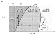
- FIG. 9 is a Ph diagram showing the relationship between the refrigerant pressure and enthalpy in the period S22 of FIG.
- a cycle C22 in which the points R221 to R225 circulate represents the refrigerant circulation in the period S22 in FIG.
- the process of state change from the point R221 to the point R222 represents the compression process of the refrigerant by the liquid pump 6.
- the process of state change from the point R222 to the point R223 represents a pressure reduction process by the expansion valve 8.
- the process of state change from the point R223 to the point R224 represents the evaporation process by the evaporator 3.
- the state change process from the point R224 to the point R225 represents the refrigerant compression process by the compressor 1.
- the process of state change from the point R225 to the point R221 represents the process of condensing the refrigerant by the condenser 2.
- the control device 32 increases the frequency of the liquid pump 6 over time, and increases the amount of refrigerant sucked by the liquid pump 6 in accordance with the increase of the liquid refrigerant in the condenser 2.
- the pressure of the refrigerant in the state of the end point of the compression process by the liquid pump 6 (start point of the pressure reduction process) R222 increases with time.
- the control device 32 increases the opening degree of the expansion valve 8 over time to reduce the pressure reducing action of the expansion valve 8. Both the pressure of the refrigerant in the state of the end point (starting point of the evaporation process) R223 and the pressure of the refrigerant in the state of the end point R224 of the evaporation process both increase.
- FIG. 10 is a Ph diagram showing the relationship between the refrigerant pressure and enthalpy in the period S23 in FIG.
- a cycle C23 that circulates in the order of points R231 to R235 represents the circulation of the refrigerant in the period S23 in FIG.
- the process of state change from the point R231 to the point R232 represents the compression process of the refrigerant by the liquid pump 6.
- the process of state change from the point R232 to the point R233 represents a process in which the refrigerant from the liquid pump 6 passes through the expansion valve 8 and reaches the evaporator 3. Since a pressure loss occurs when the refrigerant passes through the expansion valve 8 with the pipe and the opening degree fully open, the pressure decreases in the process from the point R232 to the point R233.
- the process of state change from the point R233 to the point R234 represents the process of evaporating the refrigerant by the evaporator 3.
- the state change process from the point R234 to the point R235 represents a process in which the refrigerant from the evaporator 3 passes through the check valve 7 and reaches the condenser 2.
- the process of state change from the point R235 to the point R231 represents a refrigerant condensation process by the condenser 2.
- the same effect as Embodiment 1 can be acquired.
- the refrigerant from the condenser in the vapor compression cycle (see FIG. 8), the refrigerant from the condenser is depressurized and flows into the evaporator, so that the difference between the refrigerant in the evaporator and the room temperature is different from that in the first embodiment.
- the difference between the refrigerant in the condenser and the outdoor temperature becomes larger than that in the first embodiment. Therefore, the efficiency of heat exchange between the refrigerant and the air in the evaporator and the condenser is increased, and the generation rate of the liquid refrigerant in the condenser is higher than that in the first embodiment.
- the time required until the amount of liquid refrigerant from the condenser reaches the amount necessary for the liquid pump cycle can be shortened, and the start of the liquid pump cycle can be made earlier than in the first embodiment.
- Embodiment 3 FIG. In Embodiment 3, the case where the refrigerant from the compressor or the check valve flows into the condenser via the pressure regulating valve will be described.
- the difference between the third embodiment and the first embodiment is that a pressure regulating valve is connected between the compressor and the condenser. Since the other points are the same, the description will not be repeated.
- FIG. 11 is a functional block diagram showing the configuration of the refrigeration cycle apparatus 300 according to the third embodiment.
- the outdoor unit 20 and the control device 30 in FIG. 1 are replaced with an outdoor unit 23 and a control device 33, respectively.
- the outdoor unit 23 includes an expansion valve 9 as a pressure regulating valve in addition to the configuration included in the outdoor unit 20 shown in FIG. 1.
- the expansion valve 9 is connected between the compressor 1 and the condenser 2.
- the opening degree of the expansion valve 9 is adjusted by the control device 33.
- the expansion valve 9 is, for example, an electronically controlled expansion valve (LEV: Linear Expansion Valve).
- FIG. 12 is a view showing a time chart of the frequency of the liquid pump 6, a time chart of the frequency of the compressor 1, and a time chart of the opening degree of the expansion valve 9 in the third embodiment.
- the periods S31 to S33 in FIG. 12 correspond to the periods S1 to S3 in FIG. Since the operations of the compressor 1 and the liquid pump 6 in the periods S31 to S33 are the same as those in the first embodiment, description thereof will not be repeated.
- the opening degree of the expansion valve 9 is set to the reference opening degree d2 at time tm31 when the compressor 1 is started.
- the opening degree of the expansion valve 9 increases with time until the opening degree is fully opened.
- the reference opening d2 can be appropriately determined by actual machine experiments or simulations.
- the opening degree of the expansion valve 9 is set such that, for example, the superheat degree of the refrigerant sucked into the compressor 1, the superheat degree of the refrigerant discharged from the compressor 1, or the temperature of the refrigerant discharged from the compressor 1 becomes a reference value. May be adjusted.
- the opening degree of the expansion valve 9 may be adjusted so that the difference between the pressure of the refrigerant discharged from the liquid pump 6 and the pressure of the refrigerant sucked becomes a reference value.
- the opening degree of the expansion valve 9 may be adjusted so that the degree of supercooling of the refrigerant flowing out of the condenser 2 becomes a reference value.
- FIG. 13 is a Ph diagram showing the relationship between the refrigerant pressure and enthalpy in the period S31 of FIG.
- a cycle C31 that circulates in the order of points R311 to R315 represents the circulation of the refrigerant in the period S31 in FIG.
- the process of state change from the point R311 to the point R312 represents the refrigerant compression process by the compressor 1.
- the process of state change from the point R312 to the point R313 represents a pressure reducing process by the expansion valve 9.
- the process of state change from the point R313 to the point R314 represents the process of condensing the refrigerant by the condenser 2.
- the process of state change from the point R314 to the point R315 represents a process of passing through the liquid pump 6 where the refrigerant from the condenser 2 is stopped to reach the evaporator 3.
- the process of state change from the point R315 to the point R311 represents the evaporation process of the refrigerant by the evaporator 3.
- FIG. 14 is a Ph diagram showing the relationship between the refrigerant pressure and enthalpy in the period S32 of FIG.
- a cycle C32 that circulates in the order of points R321 to R325 represents the circulation of the refrigerant in the period S32 in FIG.
- the process of state change from the point R321 to the point R322 represents the refrigerant compression process by the liquid pump 6.
- the state change process from the point R322 to the point R323 represents the refrigerant evaporation process by the evaporator 3.
- the process of state change from the point R323 to the point R324 represents the refrigerant compression process by the compressor 1.
- the process of state change from the point R324 to the point R325 represents the process of reducing the refrigerant by the expansion valve 9.
- the process of state change from the point R325 to the point R321 represents the refrigerant condensation process by the condenser 2.
- FIG. 15 is a Ph diagram showing the relationship between the refrigerant pressure and enthalpy in the period S33 in FIG.
- a cycle C33 that circulates in the order of points R331 to R334 represents the circulation of the refrigerant in the period S33 in FIG.
- the process of state change from the point R331 to the point R332 represents the refrigerant compression process by the liquid pump 6.
- the process of state change from the point R332 to the point R333 represents the refrigerant evaporation process by the evaporator 3.
- the state change process from the point R333 to the point R334 represents a process in which the refrigerant from the evaporator 3 passes through the check valve 7 and reaches the condenser 2.
- the process of state change from the point R334 to the point R331 represents the process of condensing the refrigerant by the condenser 2.
- Embodiment 3 As described above, in the refrigeration cycle apparatus according to Embodiment 3, the same effect as in Embodiment 1 can be obtained. Furthermore, in Embodiment 3, in the transition from the state where the vapor compression cycle and the liquid pump cycle are performed simultaneously (see FIG. 14) to the state where the vapor compression cycle is stopped and the liquid pump cycle is performed (see FIG. 15), The refrigerant pressure in the evaporation process is larger than the refrigerant pressure in the condensation process, and the magnitude relationship between the two is difficult to change. Therefore, in the refrigeration cycle apparatus according to Embodiment 3, it is difficult for a sudden pressure change to occur during the transition from the vapor compression cycle to the liquid pump cycle, and the liquid pump cycle can be continued stably.
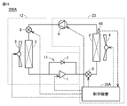
- FIG. 16 is a functional block diagram showing a configuration of a refrigeration cycle apparatus 300A according to a modification of the third embodiment.
- the indoor unit 10 and the control device 33 in FIG. 11 are replaced with the indoor unit 12 and the control device 33A, respectively.
- the indoor unit 12 is the same as the indoor unit 12 shown in FIG. 6 of the second embodiment.
- the effect similar to Embodiment 2 and Embodiment 3 can be obtained also by refrigeration cycle apparatus 300A.
Landscapes
- Engineering & Computer Science (AREA)
- Physics & Mathematics (AREA)
- Mechanical Engineering (AREA)
- Thermal Sciences (AREA)
- General Engineering & Computer Science (AREA)
- Air Conditioning Control Device (AREA)
Abstract
Ce dispositif à cycle de réfrigération effectue un refroidissement par circulation de fluide frigorigène. Le dispositif à cycle de réfrigération est pourvu d'un évaporateur, d'un condenseur, d'une pompe (6), d'un compresseur (1) et d'une unité de commande. L'évaporateur est disposé dans un premier espace. Le condenseur est disposé dans un second espace. La pompe (6) est configurée pour comprimer un fluide frigorigène provenant du condenseur et délivrer le fluide frigorigène comprimé à l'évaporateur. Le compresseur (1) est configuré pour comprimer le fluide frigorigène provenant de l'évaporateur et délivrer le fluide frigorigène comprimé au condenseur. Le dispositif de commande est configuré pour commander la pompe (6) et le compresseur (1) et pour effectuer un refroidissement du premier espace. Dans un état dans lequel la température du premier espace est supérieure à la température du second espace, le dispositif de commande est configuré pour démarrer la pompe (6) après le démarrage du compresseur (1).
Priority Applications (5)
| Application Number | Priority Date | Filing Date | Title |
|---|---|---|---|
| PCT/JP2016/087366 WO2018109894A1 (fr) | 2016-12-15 | 2016-12-15 | Dispositif à cycle de réfrigération |
| JP2018556114A JP6781268B2 (ja) | 2016-12-15 | 2016-12-15 | 冷凍サイクル装置 |
| US16/336,557 US20190293333A1 (en) | 2016-12-15 | 2016-12-15 | Refrigeration cycle apparatus |
| EP16923991.0A EP3557151B1 (fr) | 2016-12-15 | 2016-12-15 | Dispositif à cycle de réfrigération |
| US17/360,615 US20210325095A1 (en) | 2016-12-15 | 2021-06-28 | Refrigeration cycle apparatus |
Applications Claiming Priority (1)
| Application Number | Priority Date | Filing Date | Title |
|---|---|---|---|
| PCT/JP2016/087366 WO2018109894A1 (fr) | 2016-12-15 | 2016-12-15 | Dispositif à cycle de réfrigération |
Related Child Applications (2)
| Application Number | Title | Priority Date | Filing Date |
|---|---|---|---|
| US16/336,557 A-371-Of-International US20190293333A1 (en) | 2016-12-15 | 2016-12-15 | Refrigeration cycle apparatus |
| US17/360,615 Continuation-In-Part US20210325095A1 (en) | 2016-12-15 | 2021-06-28 | Refrigeration cycle apparatus |
Publications (1)
| Publication Number | Publication Date |
|---|---|
| WO2018109894A1 true WO2018109894A1 (fr) | 2018-06-21 |
Family
ID=62559621
Family Applications (1)
| Application Number | Title | Priority Date | Filing Date |
|---|---|---|---|
| PCT/JP2016/087366 Ceased WO2018109894A1 (fr) | 2016-12-15 | 2016-12-15 | Dispositif à cycle de réfrigération |
Country Status (4)
| Country | Link |
|---|---|
| US (1) | US20190293333A1 (fr) |
| EP (1) | EP3557151B1 (fr) |
| JP (1) | JP6781268B2 (fr) |
| WO (1) | WO2018109894A1 (fr) |
Cited By (2)
| Publication number | Priority date | Publication date | Assignee | Title |
|---|---|---|---|---|
| US20230349581A1 (en) * | 2022-04-28 | 2023-11-02 | Johnson Controls Tyco IP Holdings LLP | Energy efficient heat pump with counterflow heat transfer arrangement |
| JP2024135173A (ja) * | 2023-03-22 | 2024-10-04 | 富士電機株式会社 | エジェクタ冷却装置 |
Citations (9)
| Publication number | Priority date | Publication date | Assignee | Title |
|---|---|---|---|---|
| JP2000193327A (ja) * | 1998-12-25 | 2000-07-14 | Mitsubishi Electric Corp | 空気調和機および空気調和機の制御方法 |
| JP2002013781A (ja) * | 2000-06-30 | 2002-01-18 | Hitachi Ltd | 空調システム |
| JP2007132545A (ja) * | 2005-11-08 | 2007-05-31 | Taikisha Ltd | 空調システム |
| JP2007322023A (ja) * | 2006-05-30 | 2007-12-13 | Denso Corp | 廃熱利用装置を備える冷凍装置 |
| JP2010196975A (ja) * | 2009-02-25 | 2010-09-09 | Denso Corp | 冷凍サイクル装置 |
| JP2013076491A (ja) * | 2011-09-30 | 2013-04-25 | Hitachi Appliances Inc | 空気調和装置 |
| US20140157821A1 (en) * | 2012-12-07 | 2014-06-12 | Liebert Corporation | Receiver tank purge in vapor compression cooling system with pumped refrigerant economization |
| JP2016041987A (ja) * | 2014-08-15 | 2016-03-31 | 株式会社大気社 | 圧縮機/ポンプ切換式の冷却装置 |
| JP2016223743A (ja) * | 2015-06-03 | 2016-12-28 | ジョンソンコントロールズ ヒタチ エア コンディショニング テクノロジー(ホンコン)リミテッド | 空気調和装置 |
Family Cites Families (4)
| Publication number | Priority date | Publication date | Assignee | Title |
|---|---|---|---|---|
| US6584784B2 (en) * | 1999-02-05 | 2003-07-01 | Midwest Research Institute | Combined refrigeration system with a liquid pre-cooling heat exchanger |
| JP4014583B2 (ja) * | 2003-06-20 | 2007-11-28 | 株式会社デンソー | 流体機械 |
| CN101504222B (zh) * | 2009-02-19 | 2011-07-27 | 艾默生网络能源有限公司 | 一种空调 |
| US9038404B2 (en) * | 2011-04-19 | 2015-05-26 | Liebert Corporation | High efficiency cooling system |
-
2016
- 2016-12-15 WO PCT/JP2016/087366 patent/WO2018109894A1/fr not_active Ceased
- 2016-12-15 US US16/336,557 patent/US20190293333A1/en not_active Abandoned
- 2016-12-15 EP EP16923991.0A patent/EP3557151B1/fr active Active
- 2016-12-15 JP JP2018556114A patent/JP6781268B2/ja not_active Expired - Fee Related
Patent Citations (9)
| Publication number | Priority date | Publication date | Assignee | Title |
|---|---|---|---|---|
| JP2000193327A (ja) * | 1998-12-25 | 2000-07-14 | Mitsubishi Electric Corp | 空気調和機および空気調和機の制御方法 |
| JP2002013781A (ja) * | 2000-06-30 | 2002-01-18 | Hitachi Ltd | 空調システム |
| JP2007132545A (ja) * | 2005-11-08 | 2007-05-31 | Taikisha Ltd | 空調システム |
| JP2007322023A (ja) * | 2006-05-30 | 2007-12-13 | Denso Corp | 廃熱利用装置を備える冷凍装置 |
| JP2010196975A (ja) * | 2009-02-25 | 2010-09-09 | Denso Corp | 冷凍サイクル装置 |
| JP2013076491A (ja) * | 2011-09-30 | 2013-04-25 | Hitachi Appliances Inc | 空気調和装置 |
| US20140157821A1 (en) * | 2012-12-07 | 2014-06-12 | Liebert Corporation | Receiver tank purge in vapor compression cooling system with pumped refrigerant economization |
| JP2016041987A (ja) * | 2014-08-15 | 2016-03-31 | 株式会社大気社 | 圧縮機/ポンプ切換式の冷却装置 |
| JP2016223743A (ja) * | 2015-06-03 | 2016-12-28 | ジョンソンコントロールズ ヒタチ エア コンディショニング テクノロジー(ホンコン)リミテッド | 空気調和装置 |
Cited By (4)
| Publication number | Priority date | Publication date | Assignee | Title |
|---|---|---|---|---|
| US20230349581A1 (en) * | 2022-04-28 | 2023-11-02 | Johnson Controls Tyco IP Holdings LLP | Energy efficient heat pump with counterflow heat transfer arrangement |
| US12405022B2 (en) * | 2022-04-28 | 2025-09-02 | Tyco Fire & Security Gmbh | Energy efficient heat pump with counterflow heat transfer arrangement |
| JP2024135173A (ja) * | 2023-03-22 | 2024-10-04 | 富士電機株式会社 | エジェクタ冷却装置 |
| JP7810134B2 (ja) | 2023-03-22 | 2026-02-03 | 富士電機株式会社 | エジェクタ冷却装置 |
Also Published As
| Publication number | Publication date |
|---|---|
| JP6781268B2 (ja) | 2020-11-04 |
| EP3557151A1 (fr) | 2019-10-23 |
| EP3557151A4 (fr) | 2019-10-23 |
| EP3557151B1 (fr) | 2020-09-16 |
| US20190293333A1 (en) | 2019-09-26 |
| JPWO2018109894A1 (ja) | 2019-07-11 |
Similar Documents
| Publication | Publication Date | Title |
|---|---|---|
| JP5042058B2 (ja) | ヒートポンプ式給湯用室外機及びヒートポンプ式給湯装置 | |
| JP6950191B2 (ja) | 空気調和機 | |
| KR102372489B1 (ko) | 증기 분사 사이클을 이용한 공기조화장치 및 그 제어방법 | |
| US20080302118A1 (en) | Heat Pump Water Heating System Using Variable Speed Compressor | |
| JP2002081766A (ja) | 冷凍サイクル装置 | |
| JP2008241065A (ja) | 冷凍装置及び冷凍装置の油戻し方法 | |
| JP7241866B2 (ja) | 冷凍サイクル装置 | |
| JP6598882B2 (ja) | 冷凍サイクル装置 | |
| JP6388260B2 (ja) | 冷凍装置 | |
| JP2010101552A (ja) | ガスインジェクション冷凍システム | |
| JP6781268B2 (ja) | 冷凍サイクル装置 | |
| JP2006145144A (ja) | 冷凍サイクル装置 | |
| JP6576468B2 (ja) | 空気調和機 | |
| JP2016090143A (ja) | 二段圧縮式冷凍サイクル装置及びその制御装置並びに制御方法 | |
| US20180202689A1 (en) | Multi-stage compression refrigeration cycle device | |
| KR102313304B1 (ko) | 이산화탄소 공기조화기 | |
| JP2016090142A (ja) | 二段圧縮式冷凍サイクル装置及びその制御装置並びに制御方法 | |
| WO2019026731A1 (fr) | Dispositif de climatisation | |
| JP6978242B2 (ja) | 冷媒回路装置 | |
| JP2012007781A (ja) | 冷凍冷蔵庫及び冷却装置 | |
| US20210325095A1 (en) | Refrigeration cycle apparatus | |
| CN110312902B (zh) | 涡轮制冷机及涡轮制冷机的运行方法 | |
| JP5201175B2 (ja) | 空気調和装置 | |
| JP2018059666A (ja) | 制御装置、冷媒回路システム及び制御方法 | |
| KR100403017B1 (ko) | 히트펌프의 인버터 냉각장치와 냉각방법 |
Legal Events
| Date | Code | Title | Description |
|---|---|---|---|
| 121 | Ep: the epo has been informed by wipo that ep was designated in this application |
Ref document number: 16923991 Country of ref document: EP Kind code of ref document: A1 |
|
| WWE | Wipo information: entry into national phase |
Ref document number: 2018556114 Country of ref document: JP |
|
| NENP | Non-entry into the national phase |
Ref country code: DE |
|
| ENP | Entry into the national phase |
Ref document number: 2016923991 Country of ref document: EP Effective date: 20190715 |