WO2018109900A1 - 燃料供給システム - Google Patents
燃料供給システム Download PDFInfo
- Publication number
- WO2018109900A1 WO2018109900A1 PCT/JP2016/087385 JP2016087385W WO2018109900A1 WO 2018109900 A1 WO2018109900 A1 WO 2018109900A1 JP 2016087385 W JP2016087385 W JP 2016087385W WO 2018109900 A1 WO2018109900 A1 WO 2018109900A1
- Authority
- WO
- WIPO (PCT)
- Prior art keywords
- fuel supply
- pipe
- supply device
- blast furnace
- pipe member
- Prior art date
- Legal status (The legal status is an assumption and is not a legal conclusion. Google has not performed a legal analysis and makes no representation as to the accuracy of the status listed.)
- Ceased
Links
Images


Classifications
-
- C—CHEMISTRY; METALLURGY
- C21—METALLURGY OF IRON
- C21B—MANUFACTURE OF IRON OR STEEL
- C21B7/00—Blast furnaces
- C21B7/16—Tuyéres
-
- F—MECHANICAL ENGINEERING; LIGHTING; HEATING; WEAPONS; BLASTING
- F23—COMBUSTION APPARATUS; COMBUSTION PROCESSES
- F23K—FEEDING FUEL TO COMBUSTION APPARATUS
- F23K3/00—Feeding or distributing of lump or pulverulent fuel to combustion apparatus
-
- C—CHEMISTRY; METALLURGY
- C21—METALLURGY OF IRON
- C21B—MANUFACTURE OF IRON OR STEEL
- C21B5/00—Making pig-iron in the blast furnace
- C21B5/001—Injecting additional fuel or reducing agents
- C21B5/003—Injection of pulverulent coal
-
- C—CHEMISTRY; METALLURGY
- C21—METALLURGY OF IRON
- C21B—MANUFACTURE OF IRON OR STEEL
- C21B5/00—Making pig-iron in the blast furnace
- C21B5/006—Automatically controlling the process
-
- C—CHEMISTRY; METALLURGY
- C21—METALLURGY OF IRON
- C21B—MANUFACTURE OF IRON OR STEEL
- C21B7/00—Blast furnaces
- C21B7/02—Internal forms
-
- C—CHEMISTRY; METALLURGY
- C21—METALLURGY OF IRON
- C21B—MANUFACTURE OF IRON OR STEEL
- C21B7/00—Blast furnaces
- C21B7/16—Tuyéres
- C21B7/163—Blowpipe assembly
-
- C—CHEMISTRY; METALLURGY
- C21—METALLURGY OF IRON
- C21B—MANUFACTURE OF IRON OR STEEL
- C21B7/00—Blast furnaces
- C21B7/24—Test rods or other checking devices
-
- F—MECHANICAL ENGINEERING; LIGHTING; HEATING; WEAPONS; BLASTING
- F27—FURNACES; KILNS; OVENS; RETORTS
- F27D—DETAILS OR ACCESSORIES OF FURNACES, KILNS, OVENS OR RETORTS, IN SO FAR AS THEY ARE OF KINDS OCCURRING IN MORE THAN ONE KIND OF FURNACE
- F27D21/00—Arrangement of monitoring devices; Arrangement of safety devices
- F27D21/02—Observation or illuminating devices
-
- F—MECHANICAL ENGINEERING; LIGHTING; HEATING; WEAPONS; BLASTING
- F27—FURNACES; KILNS; OVENS; RETORTS
- F27D—DETAILS OR ACCESSORIES OF FURNACES, KILNS, OVENS OR RETORTS, IN SO FAR AS THEY ARE OF KINDS OCCURRING IN MORE THAN ONE KIND OF FURNACE
- F27D3/00—Charging; Discharging; Manipulation of charge
- F27D3/16—Introducing a fluid jet or current into the charge
-
- F—MECHANICAL ENGINEERING; LIGHTING; HEATING; WEAPONS; BLASTING
- F27—FURNACES; KILNS; OVENS; RETORTS
- F27D—DETAILS OR ACCESSORIES OF FURNACES, KILNS, OVENS OR RETORTS, IN SO FAR AS THEY ARE OF KINDS OCCURRING IN MORE THAN ONE KIND OF FURNACE
- F27D21/00—Arrangement of monitoring devices; Arrangement of safety devices
- F27D21/02—Observation or illuminating devices
- F27D2021/026—Observation or illuminating devices using a video installation
Definitions
- the present invention relates to a fuel supply system including a fuel supply device such as a burner for injecting fuel such as pulverized coal from a tuyere of a blast furnace into the furnace.
- a fuel supply device such as a burner for injecting fuel such as pulverized coal from a tuyere of a blast furnace into the furnace.
- fuel such as pulverized coal, heavy oil, and waste plastic is blown into the furnace from the tuyere and burned.
- a fuel such as pulverized coal is blown into the blast furnace together with hot air through a PC burner (hereinafter also simply referred to as a burner) installed in a state of penetrating a blow pipe attached to the tuyere.
- a PC burner hereinafter also simply referred to as a burner
- the lance pipe which is easily deformed can be rotated around its axis by slightly reducing the pushing force of the spring. Yes.
- the lance pipe bends due to heat, it is possible to change the position of the bent portion by rotating the lance pipe appropriately while keeping the airtight state. Since the lance pipe can be kept substantially linear for a long time, damage to the tuyere and reduction in combustion efficiency can be effectively prevented.
- the site worker When using the burner disclosed in Japanese Patent No. 5105293, the site worker directly looks at the viewing window at the blast furnace site to check the condition of the lance pipe, and when the lance pipe is bent, The worker manually rotated the lance pipe to change the position of the bend.
- the work at the site of such a blast furnace is troublesome for the field worker and the work load of the field worker increases. More specifically, in the burner disclosed in Japanese Patent No. 5105293, when the lance pipe is rotated, it is necessary to unscrew the flange member and the sleeve.
- the adapter can be rotated around the axis, so that the adapter is rotated by a predetermined angle.
- the lance pipe also rotates, so that the flange member is tightened again after being rotated by a desired amount. That is, the sleeve is rotated to tighten the screw of the sleeve to the flange member.
- the present invention has been made in view of the above points, and the driving unit can be controlled so that the pipe member is rotated by the driving unit by a control device provided separately from the fuel supply device. It is an object of the present invention to provide a fuel supply system that eliminates the need for a site worker to manually rotate a pipe member at the site of a blast furnace, thereby reducing the load on the site worker.
- a fuel supply system of the present invention is a cylindrical member that can be attached to an attachment portion provided in a blow pipe of a blast furnace, and is rotatably accommodated inside the cylindrical member, and fuel is supplied to the inside from a base end portion thereof.
- a supply device and a control device that is provided separately from the fuel supply device and controls the drive unit of the fuel supply device to rotate the rotating member and the pipe member.
- the fuel supply system of the present invention may further include an imaging device that images the pipe member of the fuel supply device inside the blast pipe of the blast furnace.
- control device includes a control unit that controls the drive unit of the fuel supply device, a display unit that displays an image of the pipe member imaged by the imaging device, and an operation unit operated by an operator. And when the command to rotate the pipe member is input by the operation unit, the control unit rotates the rotating member and the pipe member so as to rotate the pipe member. You may come to control.
- control device is configured to determine whether or not the pipe member is in a predetermined state based on an image of the pipe member imaged by the imaging device.
- the drive unit of the fuel supply apparatus may be controlled to rotate the rotating member and the pipe member when it is determined that the member is not in a predetermined state.
- control device may control the drive unit of the fuel supply device to rotate the rotating member and the pipe member by a predetermined angle every time a predetermined period elapses.
- the driving unit includes a hollow stepping motor, and the rotation member is inserted into a hollow portion of the hollow stepping motor by inserting an operation member provided in the rotation member of the fuel supply device.
- the member may be rotated by the hollow stepping motor.
- FIG. 1 It is a schematic block diagram which shows roughly the structure of the blast furnace and center operation room by embodiment of this invention. It is a block diagram which shows the structure of the fuel supply system which supplies fuel, such as pulverized coal, to the blast furnace shown in FIG. It is a side view which shows an example of a structure of the fuel supply apparatus in the fuel supply system shown in FIG. It is a longitudinal cross-sectional view which expands and shows the internal structure of the fuel supply apparatus shown in FIG. It is an exploded view of each structural member of the fuel supply apparatus shown in FIG. It is a perspective view which shows the state before a cover member is attached to the cylindrical member of the fuel supply apparatus shown in FIG.
- FIG. 1 It is a perspective view which shows a state when a cover member is attached to the cylindrical member of the fuel supply apparatus shown in FIG. It is a longitudinal cross-sectional view which shows a state when the front-end
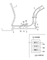
- FIG. 1 is a schematic configuration diagram schematically showing configurations of a blast furnace and a central operation room according to the present embodiment
- FIG. 2 is a fuel supply for supplying fuel such as pulverized coal to the blast furnace shown in FIG.
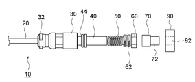
- FIG. 3 is a side view showing an example of the configuration of the fuel supply device in the fuel supply system shown in FIG. 4 is an enlarged longitudinal sectional view showing the internal configuration of the fuel supply apparatus shown in FIG. 3, and FIG.
- FIG. 5 is an exploded view of each component of the fuel supply apparatus shown in FIG.
- FIG. 6 is a perspective view showing a state before the lid member is attached to the cylindrical member of the fuel supply apparatus shown in FIG. 3, and
- FIG. 7 shows the lid on the cylindrical member of the fuel supply apparatus shown in FIG. It is a perspective view which shows a state when a member is attached.
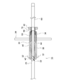
- FIG. 8 is a longitudinal sectional view showing a state where the tip of the pipe member of the fuel supply device shown in FIG. 3 is bent in the tuyere of the blast furnace.
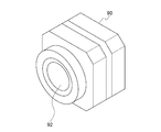
- FIG. 9 is a perspective view showing the configuration of the hollow stepping motor of the fuel supply apparatus shown in FIG.
- the blast furnace 1 is a saddle-shaped cylindrical structure in which the outside is covered with a steel plate-made iron skin and the inside is lined with a refractory.
- a hot metal and a hot metal outlet and a hot metal outlet from which the hot metal is taken out are provided separately at the lower part of the tuyere 2.
- Fuel such as pulverized coal is blown into the furnace from the tuyere 2 by a fuel supply device 10 (PC burner) described later.
- a pipe member 20 (described later) of the fuel supply device 10 is inserted into the blower pipe 4 provided in the tuyere 2 of the blast furnace 1, and a tip portion of the pipe member 20 is inserted.
- a pipe member 20 described later
- the fuel supply device 10 is inserted into the blower pipe 4 provided in the tuyere 2 of the blast furnace 1, and a tip portion of the pipe member 20 is inserted.
- the blower pipe 4 is provided with an attachment portion 5 such as a flange to which each projection 32 (described later) of the fuel supply device 10 is attached.
- a pipe member 20 (described later) of the fuel supply device 10 is inserted into the blower pipe 4.
- a viewing hole window 6 made of transparent glass or the like is provided in the blower tube 4 so that the inside of the blower tube 4 can be visually recognized by the view hole window 6.
- An imaging device 8 such as a CCD camera that images the inside of the blower tube 4 is provided outside the viewing hole window 6.
- Such an image pickup device 8 also picks up an image of the pipe member 20 of the fuel supply device 10 inserted into the blower pipe 4.
- an image or video captured by the imaging device 8 is sent to the control unit 108 of the control device 102 described later.
- a control device 102 that controls the fuel supply device 10 is provided in a central operation chamber 100 that is provided separately from the site of the blast furnace 1.
- the control device 102 includes an operation unit 104 such as a keyboard, a display unit 106 such as a large panel, and a control unit 108 such as a CPU. Images and videos captured by the imaging device 8 are displayed on the control device 102. It is displayed on the display unit 106.
- an imaging device 8 is installed.
- the display unit 106 of the control device 102 is configured to display a plurality of images and videos captured by each imaging device 8 simultaneously or in a switching manner. Further, the field worker can input various commands to the control unit 108 through the operation unit 104.
- the fuel supply device 10 includes a cylindrical member 30 (sleeve) that can be attached to an attachment portion 5 such as a flange provided in the blast pipe 4 of the blast furnace 1, and is rotatable inside the cylindrical member 30.
- a hollow rotating member 40 (adapter) that is housed and supplied with fuel from the base end portion thereof, and is detachably attached to an edge of the rotating member 40 on the blast furnace 1 side.
- a pipe member 20 (lance pipe) that is supplied to the inside 1 and a lid member 60 that can be detachably attached to the cylindrical member 30 and that accommodates the rotating member 40 inside the cylindrical member 30.
- a spring 50 is provided inside the cylindrical member 30 as a biasing member that biases a second seal surface 44 (described later) of the rotating member 40 toward a first seal surface 34 (described later) of the cylindrical member 30.
- the operation member 70 for rotating the rotation member 40 is attached to the rotation member 40 by welding, for example.
- the pipe member 20 (lance pipe) is an elongated pipe formed from a heat-resistant material such as stainless steel.
- a male screw portion 22 (second engagement portion) such as a screw thread is formed on the outer peripheral surface of the base end portion of the pipe member 20 (that is, the portion attached to the rotating member 40) (see FIG. 4). ). Further, a screw hole into which a male screw portion 22 such as a thread of the pipe member 20 is screwed into an inner peripheral surface of a tip portion (that is, a portion close to the blast furnace 1) of the hollow-shaped rotating member 40 described later.
- a female screw portion 42 (second engaged portion) is formed.
- each protrusion 32 is inserted into the hole of the attachment portion 5 and rotated to rotate the cylindrical member 30 to the blower tube 4 of the blast furnace 1. It becomes possible to fix.
- the cylindrical member 30 when fixing the cylindrical member 30 to the blower pipe 4 of the blast furnace 1, instead of inserting each protrusion 32 into the hole of the attachment portion 5 and rotating it, the cylindrical member 30 is fixed to the blast furnace 1 by a wedge such as a cotter. It may be fixed to the blower pipe 4.
- a plurality (for example, four) of blades 38 are attached to the outer peripheral surface of the cylindrical member 30 so as to extend radially.
- a first seal surface 34 is provided inside the cylindrical member 30 over the entire circumference.
- the first seal surface 34 is an inclined surface that is inclined with respect to the longitudinal direction of the cylindrical member 30 (that is, the left-right direction in FIGS. 4 and 5).
- the intermediate position in the longitudinal direction on the outer peripheral surface of the hollow rotary member 40 contacts the first seal surface 34 when housed inside the cylindrical member 30.
- a second seal surface 44 that seals between the first seal surface 34 is provided.
- the second seal surface 44 is an inclined surface that is inclined with respect to the longitudinal direction of the rotating member 40 (that is, the left-right direction in FIGS. 4 and 5).
- an operating member 70 described later is attached to the base end portion of the rotating member 40 (that is, the end portion on the side far from the blast furnace 1) by, for example, welding, and the rotating member 40 is attached by the operating member 70.
- the cylindrical member 30 can be rotated inside.
- the lid member 60 is detachably attachable to the proximal end portion of the cylindrical member 30 (that is, the end portion on the side far from the blast furnace 1), and when the lid member 60 is attached to the cylindrical member 30
- the rotating member 40 is accommodated inside the cylindrical member 30. More specifically, as shown in FIG. 5 and FIG. 6, a male screw portion 62 (first engagement) such as a screw thread is provided on the outer peripheral surface of the tip portion of the lid member 60 (that is, the portion close to the blast furnace 1). Part) is formed.
- a female screw portion 36 (first engaged portion) such as a screw hole into which a male screw portion 62 such as a screw thread of the lid member 60 is screwed to the inner peripheral surface of the proximal end portion of the cylindrical member 30. Is formed. Accordingly, the lid member 60 can be detachably attached to the proximal end portion of the cylindrical member 30. Further, as shown in FIG. 7, the lid member 60 attached to the cylindrical member 30 by inserting the rod-like lock pin 66 into the two lock holes 39 in a state where the lid member 60 is attached to the cylindrical member 30 is provided. It can be locked in the engaged state (see FIG. 7).
- the lock hole 39 and the lock pin 66 constitute a lock portion that locks the tubular member 30 and the lid member 60 in an engaged state.
- the spring 50 is accommodated around the rotating member 40 inside the cylindrical member 30, and one end of the spring 50 comes into contact with the lid member 60. .
- the spring 50 is compressed, and the compression of the spring 50 is performed.
- the rotating member 40 is pressed leftward in FIG. 4 by the restoring force from the state.
- the second seal surface 44 of the rotating member 40 is pressed toward the first seal surface 34 of the tubular member 30, and the first seal surface 34 and the second seal surface 44 are stronger. It comes in close contact with.
- the spring 50 comes to function as a biasing member that biases the second seal surface 44 of the rotating member 40 toward the first seal surface 34 of the tubular member 30, and such a biasing member.
- the first seal surface 34 and the second seal surface 44 are more firmly adhered to each other by the spring 50, so that gas and dust leak from between the first seal surface 34 and the second seal surface 44. This can be prevented more reliably.
- the operating member 70 is formed of a hollow shape, and the operating member 70 is attached to the base end portion of the rotating member 40 (that is, the portion far from the blast furnace 1) by, for example, welding. Further, the internal space of the operating member 70 and the internal space of the rotating member 40 are in communication. Further, a hollow stepping motor 90 as shown in FIG. 9 is attached to the operating member 70, and the operating member 70 is rotated by the hollow stepping motor 90. More specifically, the actuating member 70 has an actuated portion 72 having a circular cross section, and the actuated portion 72 is inserted into the hollow portion 92 of the hollow stepping motor 90. Yes. As a result, the hollow stepping motor 90 rotates the actuated portion 72 of the actuating member 70.
- the hollow stepping motor 90 is connected to the control unit 108 of the control device 102 by a signal line or the like.
- the hollow stepping motor 90 is connected to the operation member 70.
- the operating part 72 is rotated.
- a fuel supply hose 80 is connected to the operation member 70, and fuel such as pulverized coal is supplied from the hose 80 to the internal space of the operation member 70.
- the hose 80 may be attached to the hollow member after the hollow tube is attached to the actuating member 70, or after the valve is attached to the actuating member 70, A hose 80 may be attached to the valve.
- a flexible hose may be directly connected to the operating member 70, and fuel may be supplied from the flexible hose to the internal space of the operating member 70.
- the hollow stepping motor 90 When the hollow stepping motor 90 is used as a drive unit that rotationally drives the operating member 70 attached to the rotating member 40, accurate positioning control of the pipe member 20 and the rotating member 40 can be performed. Further, the hollow stepping motor 90 can rotate the pipe member 20, the rotating member 40, and the operating member 70 in either the left or right direction. Further, since such a hollow stepping motor 90 is provided around the operated portion 72 of the operating member 70, the fuel supply device 10 can be designed in a space-saving manner.
- FIG. 6 is a diagram illustrating a state when the rotating member 40 and the spring 50 are accommodated in the cylindrical member 30.
- the lid member 60 is attached to the proximal end portion of the tubular member 30 so that the rotating member 40 and the spring 50 do not come out from the proximal end portion of the tubular member 30.
- a male screw portion 62 such as a screw thread of the lid member 60 is screwed into a female screw portion 36 such as a screw hole of the cylindrical member 30.
- FIG. 7 is a view showing a state when the lid member 60 is attached to the proximal end portion of the tubular member 30.
- the proximal end portion of the pipe member 20 is attached to the distal end portion of the rotating member 40.
- a male screw portion 22 such as a screw thread of the pipe member 20 is screwed into a female screw portion 42 such as a screw hole of the rotating member 40.
- such a fuel supply device 10 the imaging device 8, and the control device 102 constitute a fuel supply system that blows fuel such as pulverized coal from the tuyere 2 of the blast furnace 1 into the furnace.
- each protrusion 32 of the cylindrical member 30 is attached to a mounting part 5 such as a flange provided in the blast pipe 4 of the blast furnace 1.
- the pipe member 20 of the fuel supply device 10 is inserted into the blower pipe 4 provided in the tuyere 2 of the blast furnace 1.
- fuel such as pulverized coal is supplied to the internal space of the operating member 70 by the fuel supply hose 80.
- fuel is blown into the furnace of the blast furnace 1 from the tip portion of the pipe member 20 through the inner space of the operating member 70, the inner space of the rotating member 40, and the inner space of the pipe member 20 in this order.
- the pipe member 20 of the fuel supply device 10 when used for a long period of time, the pipe member 20 may be bent by heat as shown in FIG. 8, and may contact the tuyere 2 and the like.
- an image or video of the pipe member 20 captured by the imaging device 8 such as a CCD camera is displayed on the display unit 106 of the control device 102 installed in the central operation room 100.
- the field worker can recognize that the pipe member 20 is bending. In this case, the field worker inputs a command to drive the hollow stepping motor 90 through the operation unit 104 of the control device 102, so that the operation member 70 is rotated by the hollow stepping motor 90.
- the pipe member 20 and the rotating member 40 can be rotated integrally, so that the position of the portion of the pipe member 20 exposed to high heat can be changed.
- the field worker appropriately rotates the pipe member 20 by the operation unit 104 of the control device 102, so that the entire area in the circumferential direction of the pipe member 20 is heated evenly, and bending in one direction is performed.
- the deformation of the pipe member 20 due to its own weight in the high temperature atmosphere can be suppressed.
- the tip portion of the pipe member 20 is easily damaged by being exposed to heat in the blast furnace 1, so that it is sometimes replaced.
- the pipe member 20 is detachable from the rotating member 40. Therefore, the rotating member 40 is removed from the cylindrical member 30 without removing the lid member 60 from the cylindrical member 30. Only the pipe member 20 can be removed in a state of being housed in the interior.
- the pipe member 20 can be replaced while the first seal surface 34 of the tubular member 30 and the second seal surface 44 of the rotating member 40 are in close contact with each other, so that the first seal surface 34 and the second seal It becomes possible to prevent dust from adhering to the surface 44 and the first seal surface 34 and the second seal surface 44 from being damaged.
- the rotating member 40 is replaced approximately once a year due to wear.
- the lid member 60 is detachable from the cylindrical member 30, so that the rotating member 40 can be replaced simply by removing the lid member 60 from the cylindrical member 30.
- the pipe member 20 in which fuel is supplied into the blast furnace 1 from the tip portion in the fuel supply device 10 is the blast furnace 1 side in the rotary member 40 having a hollow shape.
- This rotating member 40 is rotatably accommodated inside the cylindrical member 30.
- the rotating member 40 is driven to rotate by a hollow stepping motor 90.
- the hollow stepping motor 90 is controlled by the control device 102 provided separately from the fuel supply device 10 so as to rotate the rotating member 40 and the pipe member 20.
- the pipe member 20 can be maintained substantially linear for a long time, damage to the tuyere 2 of the blast furnace 1 and reduction in combustion efficiency can be effectively prevented.
- the hollow stepping motor 90 can be controlled by the control device 102 provided separately from the fuel supply device 10 so that the pipe member 20 is rotated by the hollow stepping motor 90, the field worker can be operated at the site of the blast furnace. It is not necessary to rotate the pipe member 20 by manual work, so that the load on the site worker can be reduced.
- a field worker can remotely operate the rotation operation of the pipe member 20 in the fuel supply device 10 in the central operation room 100.
- the imaging device 8 that images the pipe member 20 of the fuel supply device 10 inside the blast tube 4 of the blast furnace 1 is provided. In this case, it becomes possible to monitor the state of the pipe member 20 of the fuel supply device 10 inside the blast pipe 4 of the blast furnace 1.
- the control device 102 includes the control unit 108 that controls the hollow stepping motor 90 of the fuel supply device 10 and the pipe member 20 imaged by the imaging device 8.
- the operation unit 104 inputs a command to rotate the pipe member 20
- the display unit 106 for displaying the image is displayed and the operation unit 104 operated by an operator such as a field worker.
- the control unit 108 controls the hollow stepping motor 90 of the fuel supply apparatus 10 to rotate the rotating member 40 and the pipe member 20.
- the field worker can grasp the state of the pipe member 20 by viewing the image of the pipe member 20 captured by the imaging device 8 displayed on the display unit 106 of the control device 102.
- the site worker when the site worker recognizes that the pipe member 20 has been bent, the site worker inputs an instruction to drive the hollow stepping motor 90 by the operation unit 104 of the control device 102. .
- the operating member 70 when the operating member 70 is rotationally driven by the hollow stepping motor 90, the pipe member 20 and the rotating member 40 can be rotated integrally, and accordingly, due to the high heat at the tip portion of the pipe member 20.
- the position of the exposed part can be changed.
- the “image” displayed on the display unit 106 is a concept including not only a still image of the pipe member 20 but also an image (moving image) of the pipe member 20.
- the hollow rotary member 40 to which fuel is supplied from the base end portion is housed rotatably inside the cylindrical member 30.
- a pipe member 20 through which fuel is supplied into the blast furnace 1 from its tip portion is detachably attached to an edge of the rotating member 40 on the blast furnace 1 side, and the rotating member 40 is attached to the cylindrical member 30.
- the lid member 60 accommodated inside can be detachably attached to the cylindrical member 30.
- a seal surface (specifically, the first seal) provided between the cylindrical member 30 attached to the attachment portion 5 such as a flange provided on the blower pipe 4 of the blast furnace 1 and the rotating member 40. Since only the pipe member 20 can be replaced without exposing the surface 34 and the second seal surface 44), the load on the field worker can be reduced. That is, the lid member 60 functions as a cover that protects the first seal surface 34 and the second seal surface 44.
- the drive unit that rotationally drives the operating member 70 of the fuel supply device 10 is not limited to the hollow stepping motor 90.
- a drive unit other than the hollow stepping motor 90 may be used.
- an actuated portion 72 of the actuating member 70 may be processed into a gear shape, and the actuated portion 72 may be rotationally driven by a rack and pinion method as a drive unit.
- the imaging device 8 is not limited to a CCD camera. Any device other than a CCD camera may be used as the image pickup device 8 as long as it can pick up an image of the pipe member 20 of the fuel supply device 10 inserted into the blower tube 4.
- control device 102 is not limited to the one having the operation unit 104 such as a keyboard and the display unit 106 such as a large panel.
- the control device 102 may be provided with a touch panel, and the touch panel may function as both the operation unit 104 and the display unit 106.
- the control device 102 is not limited to being installed in the central operation room 100. Such a control device 102 may be installed in the vicinity of the blower pipe 4 at the site of the blast furnace 1. Further, as the control device 102, a portable information terminal such as a smartphone or a tablet PC may be used.
- the control unit 108 rotates the rotating member 40 and the pipe member 20.
- the method for controlling the hollow stepping motor 90 of the fuel supply apparatus 10 is not limited to such a method.
- the pipe member 20 is based on the image of the pipe member 20 of the fuel supply device 10 captured by the imaging device 8.
- the control unit 108 determines whether or not a predetermined state (specifically, a state extending linearly), and the control unit 108 determines that the pipe member 20 of the fuel supply apparatus 10 is not in the predetermined state. In this case, the control unit 108 may automatically drive the hollow stepping motor 90 of the fuel supply apparatus 10. Specifically, when the control unit 108 determines that the pipe member 20 is about to be bent based on the image of the pipe member 20 of the fuel supply device 10 captured by the imaging device 8, the control unit 108 may automatically drive the hollow stepping motor 90 of the fuel supply apparatus 10.
- the control device 102 when the pipe member 20 of the fuel supply device 10 inserted into the blower pipe 4 is in a predetermined state (that is, when it is in a state of extending linearly), the control device 102 will be described.
- a storage unit (not shown) that stores an image of the pipe member 20 is provided.
- the control part 108 compares the image of the pipe member 20 of the fuel supply apparatus 10 imaged with the imaging device 8, and the image of the pipe member 20 memorize
- the rotating member 40 is used every time a predetermined period elapses.
- the control device 102 may control the hollow stepping motor 90 of the fuel supply device 10 so as to rotate the pipe member 20 by a predetermined angle. Specifically, the control device 102 controls the hollow stepping motor 90 of the fuel supply device 10 to rotate the rotating member 40 and the pipe member 20 by, for example, 30 ° every 24 hours, for example.
- the pipe member 20 is rotated by a predetermined angle by the hollow stepping motor 90 by a predetermined angle to change the position of the bending portion without being managed by an operator such as a field worker.
- the pipe member 20 can be maintained substantially linear for a long time. In this case, it is not necessary to provide the operation unit 104 and the display unit 106 in the control device 102, and the installation of the imaging device 8 can be omitted.
- the fuel supply device used in the fuel supply system according to the present embodiment is not limited to the one having the configuration as shown in FIGS.
- Another example of the fuel supply device used in the fuel supply system according to the present embodiment will be described with reference to FIG. 10 is a longitudinal sectional view showing another example of the configuration of the fuel supply device in the fuel supply system shown in FIG.
- a fuel supply apparatus 201 (PC burner) shown in FIG. 10 includes a pipe member 202 (lance pipe) formed of a straight thin tube at the center, and a lance pipe guide (not shown) provided outside the pipe member 202. ) And an outer cylinder (not shown) provided from the front and rear intermediate portions of the lance pipe guide from the rear portion, and a connecting portion 205 is provided at the rear end portion of the fuel supply device 201.
- the pipe member 202 is a long and narrow pipe made of a heat-resistant material such as stainless steel, and a radial projection 207 is provided at the middle portion to support the center portion of the lance pipe guide.
- a radial projection 207 of the fuel supply device 201 is attached to the attachment portion 5 such as a flange provided in the blower tube 4, the pipe member 202 of the fuel supply device 201 is inserted into the blower tube 4, and the pipe The tip of the member 202 comes into the blast furnace 1 from the tuyere 2.
- connection unit 205 includes a sleeve 210, a flange member 212, and an adapter 214.
- a female screw 210 a for screwing the flange member 212 is formed on the inner surface of the sleeve 210.
- the flange member 212 has a through hole having a diameter larger than the diameter of the pipe member 202 in the core portion, and a flange 216 provided in the front end portion.
- a screw cylinder 217 is integrally provided at the rear portion of the flange 216. The male screw 217 a of the screw cylinder 217 is screwed into the female screw 210 a of the sleeve 210.
- the adapter 214 corresponds to a conventional reducer, a through hole 218 is formed in the core portion, and a diameter-expanded portion 214a to which the pipe member 202 is fitted is provided in the front end portion. From the front and rear intermediate portion to the rear portion of the through hole 218, taper holes whose diameter gradually increases on the rear side. A large-diameter mouth portion 214b to which a hose 230 for supplying pulverized coal as a raw material is connected is formed at the rear end portion of the adapter 214.
- a flange 214c is provided at the front end of the outer periphery of the adapter 214.
- a spring 222 that presses the adapter 214 forward (leftward in FIG. 10) is fitted between the flange 214c and the rear end of the sleeve 210. In the example shown in FIG. 10, the adapter 214 can move back and forth within the sleeve 210.
- a thrust bearing 220 is fitted on the outer periphery of the adapter 214. The thrust bearing 220 is for preventing the adapter 214 and the sleeve 210 from coming around.
- a chamfered inclined surface 225 is formed on the entire outer periphery of the front end of the adapter 214, and a bowl-shaped inclined surface 226 is formed on the inner periphery of the rear end of the screw cylinder 217 of the flange member 212.
- These inclined surfaces 225 and 226 are seal surfaces that are in close contact with each other, and function as a seal material (metal packing) that prevents the flow of gas when they are in close contact with each other.
- a sealing material (metal packing) opposite to the above may be formed. Good.
- a hose 230 for supplying pulverized coal is connected to the rear portion of the adapter 214.
- the rear surface of the flange 216 of the flange member 212 is in contact with the front end surface of the sleeve 210, and the rear end portion of the flange member 212 is in contact with the front end portion of the adapter 214.
- the inclined surface 226 of the flange member 212 and the inclined surface 225 of the adapter 214 are in close contact with each other, preventing the circulation of gas and dust.
- fuel such as pulverized coal, heavy oil, and waste plastic is supplied through the pipe member 202, and jetted into the furnace along with the airflow inside the blower pipe 4.
- a hollow stepping motor 290 having the same configuration as the hollow stepping motor 90 as shown in FIG. 9 is attached to the adapter 214, and the adapter 214 is rotated by the hollow stepping motor 290. More specifically, the adapter 214 has an actuated portion 214d having a circular cross section, and the actuated portion 214d is inserted into the hollow portion of the hollow stepping motor 290. . As a result, the hollow stepping motor 290 rotates the actuated portion 214 d of the adapter 214.
- the hollow stepping motor 290 is connected to the control unit 108 of the control device 102 by a signal line or the like. When a control signal is sent from the control unit 108 to the hollow stepping motor 290, the hollow stepping motor 290 is activated by the adapter 214. The portion 214d is rotated.
- the adapter 214 is provided by the control device 102 provided separately from the fuel supply device 201 as in the case of using the fuel supply device 10 shown in FIGS.
- the hollow stepping motor 290 is controlled to rotate the pipe member 202.
- the hollow stepping motor 290 can be controlled by the control device 102 provided separately from the fuel supply device 201 so that the pipe member 202 is rotated by the hollow stepping motor 290.
- the site worker does not need to manually rotate the pipe member 202 at the site of the blast furnace, thereby reducing the load on the site worker.
Landscapes
- Engineering & Computer Science (AREA)
- Chemical & Material Sciences (AREA)
- Manufacturing & Machinery (AREA)
- Materials Engineering (AREA)
- Metallurgy (AREA)
- Organic Chemistry (AREA)
- General Engineering & Computer Science (AREA)
- Mechanical Engineering (AREA)
- Combustion & Propulsion (AREA)
- Blast Furnaces (AREA)
- Furnace Charging Or Discharging (AREA)
- Manufacture Of Iron (AREA)
- Waste-Gas Treatment And Other Accessory Devices For Furnaces (AREA)
Abstract
Description
Claims (6)
- 高炉の送風管に設けられた取付部に取付可能な筒状部材、前記筒状部材の内部に回転自在に収容され、その基端部分から内部に燃料が供給される中空形状の回転部材、前記回転部材における前記高炉側の端縁に取り付けられ、その先端部分から燃料が前記高炉内に供給されるパイプ部材、および前記回転部材を回転駆動させる駆動部を有する燃料供給装置と、
前記燃料供給装置とは別に設けられ、前記回転部材および前記パイプ部材を回転させるよう前記燃料供給装置の前記駆動部を制御する制御装置と、
を備えた、燃料供給システム。 - 前記高炉の前記送風管の内部における前記燃料供給装置の前記パイプ部材を撮像する撮像装置を更に備えた、請求項1記載の燃料供給システム。
- 前記制御装置は、前記燃料供給装置の前記駆動部を制御する制御部と、前記撮像装置により撮像された前記パイプ部材の画像を表示する表示部と、作業者により操作される操作部とを有しており、前記パイプ部材を回転させる旨の指令が前記操作部により入力されたときに、前記制御部は前記回転部材および前記パイプ部材を回転させるよう前記燃料供給装置の前記駆動部を制御するようになっている、請求項2記載の燃料供給システム。
- 前記制御装置は、前記撮像装置により撮像された前記パイプ部材の画像に基づいて前記パイプ部材が所定の状態であるか否かを判断するようになっており、当該制御装置は、前記パイプ部材が所定の状態ではないと判断したときに前記回転部材および前記パイプ部材を回転させるよう前記燃料供給装置の前記駆動部を制御する、請求項2記載の燃料供給システム。
- 前記制御装置は、所定期間が経過する度に前記回転部材および前記パイプ部材を所定角度だけ回転させるよう前記燃料供給装置の前記駆動部を制御する、請求項1記載の燃料供給システム。
- 前記駆動部は中空ステッピングモータを含み、前記燃料供給装置の前記回転部材に設けられた作動部材が前記中空ステッピングモータの中空部分に装入されることによって前記回転部材が前記中空ステッピングモータにより回転させられるようになっている、請求項1乃至5のいずれか一項に記載の燃料供給システム。
Priority Applications (8)
| Application Number | Priority Date | Filing Date | Title |
|---|---|---|---|
| UAA201800274A UA122147C2 (uk) | 2016-12-15 | 2016-12-15 | Система подачі палива |
| EP16904242.1A EP3556871A4 (en) | 2016-12-15 | 2016-12-15 | FUEL DISTRIBUTION SYSTEM |
| JP2017544789A JP6431614B2 (ja) | 2016-12-15 | 2016-12-15 | 燃料供給システム |
| KR1020177031615A KR102077377B1 (ko) | 2016-12-15 | 2016-12-15 | 연료 공급 시스템 |
| CN201680031957.XA CN108463564A (zh) | 2016-12-15 | 2016-12-15 | 燃料供给系统 |
| PCT/JP2016/087385 WO2018109900A1 (ja) | 2016-12-15 | 2016-12-15 | 燃料供給システム |
| RU2018100127A RU2674094C1 (ru) | 2016-12-15 | 2016-12-15 | Система подачи топлива |
| TW106129504A TWI643956B (zh) | 2016-12-15 | 2017-08-30 | Fuel supply system |
Applications Claiming Priority (1)
| Application Number | Priority Date | Filing Date | Title |
|---|---|---|---|
| PCT/JP2016/087385 WO2018109900A1 (ja) | 2016-12-15 | 2016-12-15 | 燃料供給システム |
Publications (1)
| Publication Number | Publication Date |
|---|---|
| WO2018109900A1 true WO2018109900A1 (ja) | 2018-06-21 |
Family
ID=62558155
Family Applications (1)
| Application Number | Title | Priority Date | Filing Date |
|---|---|---|---|
| PCT/JP2016/087385 Ceased WO2018109900A1 (ja) | 2016-12-15 | 2016-12-15 | 燃料供給システム |
Country Status (8)
| Country | Link |
|---|---|
| EP (1) | EP3556871A4 (ja) |
| JP (1) | JP6431614B2 (ja) |
| KR (1) | KR102077377B1 (ja) |
| CN (1) | CN108463564A (ja) |
| RU (1) | RU2674094C1 (ja) |
| TW (1) | TWI643956B (ja) |
| UA (1) | UA122147C2 (ja) |
| WO (1) | WO2018109900A1 (ja) |
Families Citing this family (1)
| Publication number | Priority date | Publication date | Assignee | Title |
|---|---|---|---|---|
| CN118293424B (zh) * | 2024-06-04 | 2024-10-01 | 常州大业能源科技有限公司 | 水燃料氢氧机 |
Citations (6)
| Publication number | Priority date | Publication date | Assignee | Title |
|---|---|---|---|---|
| JPS515293B1 (ja) | 1968-01-26 | 1976-02-19 | ||
| JPH0274350U (ja) * | 1988-11-28 | 1990-06-06 | ||
| JP2000129320A (ja) * | 1998-10-28 | 2000-05-09 | Nkk Corp | 高炉吹込み用ランスの移動装置 |
| JP2012219336A (ja) * | 2011-04-10 | 2012-11-12 | Toraitekku:Kk | 高炉の微粉炭吹き込みバーナー |
| JP2015021151A (ja) * | 2013-07-18 | 2015-02-02 | 新日鐵住金株式会社 | 微粉炭吹き込み回転式ランス |
| JP2015025188A (ja) * | 2013-07-29 | 2015-02-05 | Jfeスチール株式会社 | 異常検知方法および高炉操業方法 |
Family Cites Families (8)
| Publication number | Priority date | Publication date | Assignee | Title |
|---|---|---|---|---|
| DE69322002T2 (de) * | 1992-07-01 | 1999-04-01 | Paul Wurth S.A., Luxemburg/Luxembourg | Vorrichtung zum Einblasen von Kohlenstaub in einen Hochofen |
| JPH10237515A (ja) * | 1997-02-26 | 1998-09-08 | Azuma Tekko Kk | 高炉用ランス管 |
| JP3896709B2 (ja) * | 1998-10-30 | 2007-03-22 | Jfeスチール株式会社 | 高清浄度鋼の溶製方法 |
| KR100477063B1 (ko) * | 2002-11-14 | 2005-03-17 | 주식회사 포스코 | 조업중 회전과 전후진이 가능한 미분탄 취입랜스 |
| KR100992881B1 (ko) * | 2008-09-25 | 2010-11-09 | 주식회사 삼우에코 | 길이와 각도조절이 가능한 미분탄 혼합장치 및 그 제어방법 |
| LU91543B1 (en) * | 2009-03-24 | 2010-09-27 | Wurth Paul Sa | Tuyere stock arrangement for a blast furnace and method for operating a blast furnace |
| CN102220444B (zh) * | 2011-07-08 | 2013-06-12 | 中冶南方工程技术有限公司 | 高炉喷煤系统分配器喷煤支管防堵控制系统 |
| JP3186349U (ja) * | 2013-07-19 | 2013-10-03 | 栗田鑿岩機株式会社 | 微粉炭吹き込み回転式ランス |
-
2016
- 2016-12-15 JP JP2017544789A patent/JP6431614B2/ja active Active
- 2016-12-15 CN CN201680031957.XA patent/CN108463564A/zh active Pending
- 2016-12-15 EP EP16904242.1A patent/EP3556871A4/en not_active Withdrawn
- 2016-12-15 RU RU2018100127A patent/RU2674094C1/ru active
- 2016-12-15 WO PCT/JP2016/087385 patent/WO2018109900A1/ja not_active Ceased
- 2016-12-15 KR KR1020177031615A patent/KR102077377B1/ko not_active Expired - Fee Related
- 2016-12-15 UA UAA201800274A patent/UA122147C2/uk unknown
-
2017
- 2017-08-30 TW TW106129504A patent/TWI643956B/zh not_active IP Right Cessation
Patent Citations (6)
| Publication number | Priority date | Publication date | Assignee | Title |
|---|---|---|---|---|
| JPS515293B1 (ja) | 1968-01-26 | 1976-02-19 | ||
| JPH0274350U (ja) * | 1988-11-28 | 1990-06-06 | ||
| JP2000129320A (ja) * | 1998-10-28 | 2000-05-09 | Nkk Corp | 高炉吹込み用ランスの移動装置 |
| JP2012219336A (ja) * | 2011-04-10 | 2012-11-12 | Toraitekku:Kk | 高炉の微粉炭吹き込みバーナー |
| JP2015021151A (ja) * | 2013-07-18 | 2015-02-02 | 新日鐵住金株式会社 | 微粉炭吹き込み回転式ランス |
| JP2015025188A (ja) * | 2013-07-29 | 2015-02-05 | Jfeスチール株式会社 | 異常検知方法および高炉操業方法 |
Non-Patent Citations (1)
| Title |
|---|
| See also references of EP3556871A4 |
Also Published As
| Publication number | Publication date |
|---|---|
| RU2674094C1 (ru) | 2018-12-04 |
| TWI643956B (zh) | 2018-12-11 |
| JPWO2018109900A1 (ja) | 2018-12-20 |
| KR102077377B1 (ko) | 2020-02-13 |
| JP6431614B2 (ja) | 2018-11-28 |
| TW201823475A (zh) | 2018-07-01 |
| CN108463564A (zh) | 2018-08-28 |
| KR20180087139A (ko) | 2018-08-01 |
| EP3556871A4 (en) | 2020-08-26 |
| UA122147C2 (uk) | 2020-09-25 |
| EP3556871A1 (en) | 2019-10-23 |
Similar Documents
| Publication | Publication Date | Title |
|---|---|---|
| US6229563B1 (en) | Camera insertion into a furnace | |
| WO2004002136A1 (fr) | Camera video a brancher pour four et systeme de traitement d'images | |
| JP6431614B2 (ja) | 燃料供給システム | |
| WO2003025488A1 (en) | Internal-surveillance-purpose vision tube, composed of block lens and camera block | |
| JP5968835B2 (ja) | 微粉炭吹き込み回転式ランス | |
| EP3256610B1 (en) | Optical monitoring system for observing internal conditions in the tuyere zone of a blast furnace | |
| JP5105293B2 (ja) | 高炉の微粉炭吹き込みバーナー | |
| EP4067798A1 (en) | An inspection apparatus and method for using an inspection apparatus | |
| KR101996621B1 (ko) | 화로용 카메라 장치, 이를 위한 컨버터 및 허브 시스템 | |
| US6034345A (en) | Apparatus for repairing high temperature process vessels | |
| JP3170318B2 (ja) | 炉内観察装置 | |
| JP6347896B2 (ja) | 燃料供給装置 | |
| KR100992881B1 (ko) | 길이와 각도조절이 가능한 미분탄 혼합장치 및 그 제어방법 | |
| CN212537436U (zh) | 一种用于高温工业窑炉的高温工业电视安装云台 | |
| JP3186349U (ja) | 微粉炭吹き込み回転式ランス | |
| WO2014076847A1 (ja) | 高炉の微粉炭吹き込みバーナー | |
| CN212664304U (zh) | 一种炉内摄像仪的清灰装置 | |
| JP7261106B2 (ja) | 煙突内壁面の吹付け補修構造及び吹付け補修方法 | |
| JP3603181B2 (ja) | コークス炉炉壁の補修装置 | |
| TWI892994B (zh) | 用於維護冶金爐的冷卻組件的方法 | |
| CN107175614A (zh) | 用于更换枪芯的拔枪芯装置 | |
| JPH10168507A (ja) | 高炉用ランス |
Legal Events
| Date | Code | Title | Description |
|---|---|---|---|
| ENP | Entry into the national phase |
Ref document number: 2017544789 Country of ref document: JP Kind code of ref document: A |
|
| ENP | Entry into the national phase |
Ref document number: 20177031615 Country of ref document: KR Kind code of ref document: A |
|
| WWE | Wipo information: entry into national phase |
Ref document number: 2018100127 Country of ref document: RU |
|
| 121 | Ep: the epo has been informed by wipo that ep was designated in this application |
Ref document number: 16904242 Country of ref document: EP Kind code of ref document: A1 |
|
| NENP | Non-entry into the national phase |
Ref country code: DE |