WO2018109941A1 - Usine de fabrication d'articles absorbants - Google Patents
Usine de fabrication d'articles absorbants Download PDFInfo
- Publication number
- WO2018109941A1 WO2018109941A1 PCT/JP2016/087640 JP2016087640W WO2018109941A1 WO 2018109941 A1 WO2018109941 A1 WO 2018109941A1 JP 2016087640 W JP2016087640 W JP 2016087640W WO 2018109941 A1 WO2018109941 A1 WO 2018109941A1
- Authority
- WO
- WIPO (PCT)
- Prior art keywords
- floor
- nonwoven fabric
- feeding
- material coil
- feeding device
- Prior art date
- Legal status (The legal status is an assumption and is not a legal conclusion. Google has not performed a legal analysis and makes no representation as to the accuracy of the status listed.)
- Ceased
Links
Images




Classifications
-
- A—HUMAN NECESSITIES
- A61—MEDICAL OR VETERINARY SCIENCE; HYGIENE
- A61F—FILTERS IMPLANTABLE INTO BLOOD VESSELS; PROSTHESES; DEVICES PROVIDING PATENCY TO, OR PREVENTING COLLAPSING OF, TUBULAR STRUCTURES OF THE BODY, e.g. STENTS; ORTHOPAEDIC, NURSING OR CONTRACEPTIVE DEVICES; FOMENTATION; TREATMENT OR PROTECTION OF EYES OR EARS; BANDAGES, DRESSINGS OR ABSORBENT PADS; FIRST-AID KITS
- A61F13/00—Bandages or dressings; Absorbent pads
- A61F13/15—Absorbent pads, e.g. sanitary towels, swabs or tampons for external or internal application to the body; Supporting or fastening means therefor; Tampon applicators
- A61F13/15577—Apparatus or processes for manufacturing
- A61F13/15804—Plant, e.g. involving several steps
-
- E—FIXED CONSTRUCTIONS
- E04—BUILDING
- E04H—BUILDINGS OR LIKE STRUCTURES FOR PARTICULAR PURPOSES; SWIMMING OR SPLASH BATHS OR POOLS; MASTS; FENCING; TENTS OR CANOPIES, IN GENERAL
- E04H5/00—Buildings or groups of buildings for industrial or agricultural purposes
- E04H5/02—Buildings or groups of buildings for industrial purposes, e.g. for power-plants or factories
-
- A—HUMAN NECESSITIES
- A61—MEDICAL OR VETERINARY SCIENCE; HYGIENE
- A61F—FILTERS IMPLANTABLE INTO BLOOD VESSELS; PROSTHESES; DEVICES PROVIDING PATENCY TO, OR PREVENTING COLLAPSING OF, TUBULAR STRUCTURES OF THE BODY, e.g. STENTS; ORTHOPAEDIC, NURSING OR CONTRACEPTIVE DEVICES; FOMENTATION; TREATMENT OR PROTECTION OF EYES OR EARS; BANDAGES, DRESSINGS OR ABSORBENT PADS; FIRST-AID KITS
- A61F13/00—Bandages or dressings; Absorbent pads
- A61F13/15—Absorbent pads, e.g. sanitary towels, swabs or tampons for external or internal application to the body; Supporting or fastening means therefor; Tampon applicators
-
- A—HUMAN NECESSITIES
- A61—MEDICAL OR VETERINARY SCIENCE; HYGIENE
- A61F—FILTERS IMPLANTABLE INTO BLOOD VESSELS; PROSTHESES; DEVICES PROVIDING PATENCY TO, OR PREVENTING COLLAPSING OF, TUBULAR STRUCTURES OF THE BODY, e.g. STENTS; ORTHOPAEDIC, NURSING OR CONTRACEPTIVE DEVICES; FOMENTATION; TREATMENT OR PROTECTION OF EYES OR EARS; BANDAGES, DRESSINGS OR ABSORBENT PADS; FIRST-AID KITS
- A61F13/00—Bandages or dressings; Absorbent pads
- A61F13/15—Absorbent pads, e.g. sanitary towels, swabs or tampons for external or internal application to the body; Supporting or fastening means therefor; Tampon applicators
- A61F13/15577—Apparatus or processes for manufacturing
- A61F13/15764—Transferring, feeding or handling devices; Drives
-
- B—PERFORMING OPERATIONS; TRANSPORTING
- B65—CONVEYING; PACKING; STORING; HANDLING THIN OR FILAMENTARY MATERIAL
- B65H—HANDLING THIN OR FILAMENTARY MATERIAL, e.g. SHEETS, WEBS, CABLES
- B65H19/00—Changing the web roll
- B65H19/10—Changing the web roll in unwinding mechanisms or in connection with unwinding operations
- B65H19/12—Lifting, transporting, or inserting the web roll; Removing empty core
-
- B—PERFORMING OPERATIONS; TRANSPORTING
- B65—CONVEYING; PACKING; STORING; HANDLING THIN OR FILAMENTARY MATERIAL
- B65H—HANDLING THIN OR FILAMENTARY MATERIAL, e.g. SHEETS, WEBS, CABLES
- B65H2301/00—Handling processes for sheets or webs
- B65H2301/40—Type of handling process
- B65H2301/41—Winding, unwinding
- B65H2301/417—Handling or changing web rolls
- B65H2301/41702—Handling or changing web rolls management and organisation of stock and production
-
- B—PERFORMING OPERATIONS; TRANSPORTING
- B65—CONVEYING; PACKING; STORING; HANDLING THIN OR FILAMENTARY MATERIAL
- B65H—HANDLING THIN OR FILAMENTARY MATERIAL, e.g. SHEETS, WEBS, CABLES
- B65H2301/00—Handling processes for sheets or webs
- B65H2301/40—Type of handling process
- B65H2301/41—Winding, unwinding
- B65H2301/417—Handling or changing web rolls
- B65H2301/41704—Handling or changing web rolls involving layout of production or storage facility
-
- B—PERFORMING OPERATIONS; TRANSPORTING
- B65—CONVEYING; PACKING; STORING; HANDLING THIN OR FILAMENTARY MATERIAL
- B65H—HANDLING THIN OR FILAMENTARY MATERIAL, e.g. SHEETS, WEBS, CABLES
- B65H2601/00—Problem to be solved or advantage achieved
- B65H2601/50—Diminishing, minimizing or reducing
- B65H2601/51—Diminishing, minimizing or reducing entities relating to handled material
- B65H2601/511—Waste of handled material
-
- B—PERFORMING OPERATIONS; TRANSPORTING
- B65—CONVEYING; PACKING; STORING; HANDLING THIN OR FILAMENTARY MATERIAL
- B65H—HANDLING THIN OR FILAMENTARY MATERIAL, e.g. SHEETS, WEBS, CABLES
- B65H2701/00—Handled material; Storage means
- B65H2701/10—Handled articles or webs
- B65H2701/19—Specific article or web
- B65H2701/1924—Napkins or tissues, e.g. dressings, toweling, serviettes, kitchen paper and compresses
-
- B—PERFORMING OPERATIONS; TRANSPORTING
- B65—CONVEYING; PACKING; STORING; HANDLING THIN OR FILAMENTARY MATERIAL
- B65H—HANDLING THIN OR FILAMENTARY MATERIAL, e.g. SHEETS, WEBS, CABLES
- B65H2801/00—Application field
- B65H2801/57—Diaper manufacture
Definitions
- the present invention relates to a manufacturing plant for absorbent articles such as disposable diapers and sanitary napkins.
- the articles are manufactured using a plurality of types of materials.
- Patent Document 1 discloses a so-called mezzanine style, that is, a mezzanine style building, as an example of the building of the manufacturing factory. And on the mezzanine floor, a feeding device for feeding materials from a plurality of types of material coils is arranged for each of the above types, and each of the fed materials is conveyed and supplied to the first floor. On the other hand, a processing unit is provided on the first floor. And while processing the plurality of types of materials supplied from the mezzanine, the processing unit performs various types of processing such as pressing and joining on the materials, thereby manufacturing absorbent articles. .
- the building style is the mezzanine style.
- the wall is not well partitioned.
- the present invention has been made in view of the above-described problems, and the purpose of the present invention is that in the lower floor having a processed portion, fiber waste that can be scattered when a nonwoven fabric is fed out from a material coil as a kind of material. It is to prevent the material from adhering to and fouling it.
- the main invention for achieving the above object is: It is a manufacturing factory that manufactures absorbent articles using multiple types of materials, A building having an upper floor and a lower floor located below the upper floor;
- the upper floor has a floor, a wall provided along the entire periphery of the floor, a lighting device provided on the ceiling, and an air conditioner equipped with an air outlet that blows out air.
- the lower floor has a floor, a wall provided along the entire periphery of the floor, an illumination device provided on the ceiling, and an air conditioner equipped with a blowout port for blowing out air
- the floor of the upper floor is formed with an opening communicating the upper floor and the lower floor
- the upper floor is provided with a feeding device that is attached with a material coil around which a nonwoven fabric is wound as at least one of the plurality of types of materials and feeds the nonwoven fabric
- the lower floor is provided with a processing section that processes the plurality of types of materials including the nonwoven fabric conveyed from the upper floor through the opening. It is a manufacturing factory.
- FIG. 3 is a view taken along arrows III-III in FIGS. 1 and 2.
- FIG. 5A is an explanatory diagram of the feeding device 30 for the sheet-shaped material 1ST showing the V portion in FIG. 3 in an enlarged manner
- FIG. 5B is a view taken along the line BB in FIG. 5A
- FIG. 6 is a view taken along arrow VI-VI in FIG. 1.
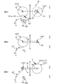
- 7A to 7C are explanatory views of the first-type feeding device 30.
- FIG. 9A to 9C are explanatory views of the second type feeding device 30.
- FIG. It is the schematic plan view which looked at the turn bar 50 from the upper part. It is a schematic side view of the production
- a building having an upper floor and a lower floor located below the upper floor;
- the upper floor has a floor, a wall provided along the entire periphery of the floor, a lighting device provided on the ceiling, and an air conditioner equipped with an air outlet that blows out air.
- the lower floor has a floor, a wall provided along the entire periphery of the floor, an illumination device provided on the ceiling, and an air conditioner equipped with a blowout port for blowing out air
- the floor of the upper floor is formed with an opening communicating the upper floor and the lower floor
- the upper floor is provided with a feeding device that is attached with a material coil around which a nonwoven fabric is wound as at least one of the plurality of types of materials and feeds the nonwoven fabric
- the lower floor is provided with a processing section that processes the plurality of types of materials including the nonwoven fabric conveyed from the upper floor through the opening. It is a manufacturing factory.
- the upper floor at least when the above-described feeding device feeds the nonwoven fabric from the material coil, there is a risk that fiber waste will be scattered.
- All kinds of non-woven fabrics included in the plurality of types of materials other than the non-woven fabric are each carried into the building in the form of a material coil wound with the non-woven fabric,
- the upper floor is preferably provided with a feeding device for feeding the non-woven fabric from the material coil in correspondence with each of the all types of non-woven fabric.
- the lower floor is provided with a feeding device that attaches a material coil around which a non-nonwoven material that is not a nonwoven fabric is wound as at least one of the plurality of types of materials and feeds the non-woven material.
- non-nonwoven material as at least one of a plurality of types of materials is fed from the material coil on the lower floor and conveyed to the processing section on the lower floor. Therefore, shortening of the conveyance distance to the process part of the said non-woven fabric material can be aimed at, and it becomes possible to suppress effectively the stain
- a manufacturing plant for such absorbent articles Each of the plurality of types of materials is carried into the building in the form of a material coil around which the materials are wound, and the material coil is attached to a feeding device provided corresponding to each of the plurality of types.
- the material is fed out from the material coil, Among the material coils of the plurality of types of materials, the material coil fed out by the feeding device on the upper floor is stored in the storage area on the upper floor, Of the material coils of the plurality of types of materials, the material coil fed out by the feeding device on the lower floor is preferably stored in the storage area on the lower floor.
- the material coil is stored in the storage area on the same lower floor with respect to the material fed by the lower floor feeding device. Therefore, it is suppressed reliably that the fiber waste scattered from said nonwoven fabric drawn
- a manufacturing plant for such absorbent articles A wall portion is provided between a feeding area where the feeding device is provided on the upper floor and the storage area on the upper floor, It is desirable that a wall portion be provided between a feeding area where the feeding device is provided on the lower floor and the storage area on the lower floor.
- the wall is provided between the feeding area and the storage area on the upper floor. Therefore, when the above-mentioned nonwoven fabric is fed out by the feeding device in the upper-floor feeding area, the fiber scraps scattered from the nonwoven fabric adhere to other material coils stored in the upper-floor storage area and deface it. This can be effectively suppressed.
- a wall portion is provided between the feeding area and the storage area on the lower floor. Therefore, even if the non-woven fabric may be fed out as a material in the feeding device in the lower-floor feeding area, fiber scraps scattered from the nonwoven fabric adhere to other material coils being stored in the lower-floor storage area. Thus, it is possible to effectively suppress the contamination.
- a manufacturing plant for such absorbent articles The transport roller with which the nonwoven fabric first fed out from the material coil by the feeding device on the upper floor comes into contact is located on the upper floor,
- the contact surface that contacts the transport roller in the nonwoven fabric is non-contact that does not contact the support surface when the constituent fibers of the nonwoven fabric are sucked and deposited on the support surface of the support member to form the nonwoven fabric. It is desirable to be a surface.
- the contact surface which contacts a conveyance roller in a nonwoven fabric is a non-contact surface which does not contact
- the atmospheric pressure at the boundary position between the lower floor space and the opening is preferably larger than the atmospheric pressure at the boundary position between the upper floor space and the opening.
- the pressure on the lower floor is greater than the pressure on the upper floor. Therefore, it is possible to prevent the upper floor textile waste from entering the lower floor through the opening.
- the amount (g / m 3 ) of fibers contained per unit volume at the boundary position between the lower floor space and the opening is included per unit volume at the boundary position between the upper floor space and the opening. It is desirable that the amount be less than the amount of fiber (g / m 3 ).
- the amount of fibers (g / m 3 ) contained in the lower floor is smaller than the amount of fibers (g / m 3 ) contained in the upper floor. Therefore, it becomes possible to effectively suppress the contamination of the material due to the fiber scrap on the lower floor having the processed portion.
- a manufacturing plant for such absorbent articles When seeing through the building from above, It is desirable that the opening is disposed so that at least a part of the opening overlaps the processed portion.
- the above-described opening for passing the non-woven fabric drawn out on the upper floor to the lower floor is arranged almost immediately above the processing section on the lower floor. Therefore, the conveyance route to the process part in the same lower floor of the nonwoven fabric conveyed to the lower floor through the said opening part can be shortened. And thereby, a malfunction that may occur when the transport route to the processing section on the lower floor is long, that is, a lot of fiber scraps are scattered from the nonwoven fabric to the lower floor during transport on the long transport route and contaminate the lower floor. Can be effectively prevented.
- the feeding device is arranged so that at least a part of the feeding device that feeds the nonwoven fabric overlaps the processed portion.
- the above-mentioned nonwoven fabric feeding device is arranged on the upper floor almost directly above the processing section. Therefore, the planar size of the building can be made compact as a whole.
- the non-woven fabric is a first non-woven fabric
- the material coil around which the non-woven fabric is wound is a first material coil
- the non-woven fabric feeding device is a first feeding device
- the plurality of types of materials are
- the second floor includes a second nonwoven fabric different from the nonwoven fabric
- the upper floor is provided with a second feeding device for attaching the second material coil around which the second nonwoven fabric is wound and feeding the second nonwoven fabric
- the first feeding device has a feeding rotating shaft for attaching the preceding first material coil and a feeding rotating shaft for attaching the following first material coil.
- the first nonwoven fabric of the first material coil of the succeeding is moved to the first material coil of the preceding first material coil.
- Has a material splicing function to connect to the first nonwoven fabric While the rotation of the feeding rotating shaft is stopped, the first floor accumulated in the form of a plurality of loops with a plurality of rolls arranged between the first feeding device and the processing unit on the upper floor.
- the second feeding device has a feeding rotary shaft to which the preceding second material coil is attached and a feeding rotary shaft to which the second material coil is attached, and the second feeding device is The second nonwoven fabric of the second material coil in the preceding second material coil is connected to the second nonwoven fabric of the second material coil in the preceding material in a state where both the preceding rotating shaft for feeding and the following rotating shaft for feeding are rotated. It is desirable to have a material splicing function that connects to the nonwoven fabric.
- the first nonwoven fabric forms a plurality of loops with the plurality of rolls, and the first nonwoven fabric contacts the plurality of rolls on the upper floor. Therefore, most of the constituent fibers to be dropped from the first non-woven fabric at the time of contact are dropped and scattered as fiber waste, and as a result, after passing through the plurality of rolls, the first non-woven fabric has almost no constituent fibers that are likely to fall off. There will be no state. And thereby, it is suppressed effectively that fiber scraps scatter from a 1st nonwoven fabric after conveyance to a lower floor.
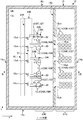
- FIG. 1 is a schematic plan view of the first floor of the absorbent article manufacturing factory 10 of the present embodiment as viewed from above
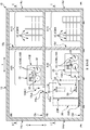
- FIG. 2 is a schematic plan view of the second floor as viewed from above
- FIG. 3 is a view taken in the direction of arrows III-III in FIGS. 1 and FIG. 2 are views taken along arrows II and II-II in FIG. 3, respectively.
- the absorbent article manufacturing factory 10 uses a plurality of types of materials 1 to manufacture absorbent articles.
- a deployment type or underpants type disposable diaper, a sanitary napkin, a urine collecting pad, etc. can be mentioned.
- it is not limited to the above as long as it is an article that can absorb the excrement of the wearer.
- a nonwoven fabric continuum 1NW hereinafter also simply referred to as a nonwoven fabric 1NW
- a film continuum hereinafter also simply referred to as a film
- a tape continuum hereinafter also simply referred to as a tape.
- tissue paper A continuous body of tissue paper (hereinafter also simply referred to as tissue paper), a continuous body of elastic thread such as rubber thread (hereinafter also simply referred to as elastic thread), and the like.
- elastic thread a continuous body of elastic thread such as rubber thread
- the material 1 is further prepared and used for each type.
- the manufacturing factory 10 includes a building 12 constructed by RC construction, S construction, SRC construction, etc. on all the second floors as an example of a plurality of floors.
- the building 12 is built on a foundation (not shown) such as a solid foundation or a pile foundation.
- the first floor as the lower floor has a floor portion 13d and wall portions 14d, 14d provided along the entire peripheral edge of the floor portion 13d, and the second floor as the upper floor also has the floor portion 13u.
- wall portions 14u, 14u,... Provided along the entire periphery of the floor portion 13u.
- the planar shapes of the floor portions 13d and 13u on the first floor and the second floor viewed from above are both rectangular.
- walls 14d, 14d... Are provided on the four sides of the floor 13d on the first floor, and similarly, walls 14u, 14u... Are provided on the four sides of the floor 13u on the second floor.
- the second floor is surrounded by the floor portion 13u of the second floor and the four wall portions 14u, 14u... Of the second floor, and as a result, the second floor is generally isolated from the first floor.
- the building 12 also has a roof 15, which also serves as a ceiling on the second floor.
- the floor 13u on the second floor also serves as the ceiling on the first floor. That is, the floor portion 13u on the second floor is connected to the four wall portions 14d, 14d,.
- appropriate lighting devices such as LED lighting are discretely arranged to illuminate the corresponding floors.
- air outlets are provided at appropriate positions on the first and second floors. And by blowing out air from these outlets, each atmospheric pressure (Pa) on the first floor and the second floor is maintained in a positive pressure state larger than the atmospheric pressure (Pa) outside the building 12, and as a result, inside the building 12 Invasion of insects, dust, and the like into the building 12 is prevented by suppressing the entry of outside air into the building 12.
- an opening / closing door may be provided as an entrance of the building 12 in at least one of the four wall portions 14d, 14d ... on the first floor.
- a window may be provided on each of the first and second floor walls.
- a stairs (not shown) that connects the first floor and the second floor may be provided in the building 12, or an outdoor stairs that connects the ground and the second floor is provided outside the building 12. May be.
- an opening / closing door is provided on at least one of the four wall portions 14u, 14u,.
- the floor portion 13u and the roof 15 on the second floor may be supported by pillars and beams (not shown) provided on each floor, or the above-mentioned wall portions 14d and 14u on the first floor and the second floor are structured. And may be supported by these wall portions 14d and 14u.
- the first floor of the building 12 is provided with a processing unit 20 that substantially manufactures absorbent articles using a plurality of types of materials 1. That is, the processing unit 20 processes the material 1 while conveying the plurality of types of materials 1 in the flow direction D1. More specifically, a plurality of types of materials 1 are fed out by corresponding later-described feeding devices 30, and the various materials 1 fed out are joined at the processing unit 20 and conveyed in the flow direction D ⁇ b> 1. While being transported in the flow direction D1, the various materials 1 are subjected to various processing processes such as pressing, cutting, joining, etc. by various processing devices 22, 22. The absorbent article is finally produced by polymerization or the like.
- Examples of the processing device 22 include a known welding device that welds the materials 1 and 1, a known pressing device that presses the material 1, a known cutter device that cuts part or all of the material 1, and the like. Can be mentioned.
- the processing unit 20 on the first floor may have a protective cover 21 as virtually indicated by a three-dot chain line in FIG. 3, and in this case, the protective cover 21 is connected to the processing unit 20. It distribute
- FIG. Incidentally, the reason why the protective cover 21 should be provided on the first floor is that the first floor is more frequent than the second floor when an operator enters the operating state of each processing device 22 provided on the first floor.
- the protective cover 21 may have an open / close door at a position facing each processing device 22, 22... In the flow direction D1. And if it becomes like this, at the time of trouble of each processing apparatus 22, an operator can open the opening-and-closing door and can access the processing apparatus 22 rapidly, and thereby shortening the recovery time of the apparatus 22 I can plan.
- two horizontal directions that are orthogonal to each other while being orthogonal to the vertical direction are also referred to as “X direction” and “Y direction”.
- the flow direction D1 is along the Y direction in plan view.
- a plurality of types of materials 1 are brought into the building 12 in the form of a material coil 1C around which the material 1 is wound. Therefore, as shown in FIGS. 1 to 3, a feed area A ⁇ b> 30 for feeding the material 1 from the material coil 1 ⁇ / b> C is provided in the building 12.
- the feeding area 30 is provided with a feeding device 30 corresponding to each type of material 1.
- the material coil 1 ⁇ / b> C is attached to the corresponding feeding device 30 and fed out.
- the feeding area A30 is provided on both the first floor and the second floor.
- the first floor feed area A30 is a long region along the flow direction D1 of the processing unit 20. That is, on the first floor, a plurality of feeding devices 30, 30... Are arranged along the flow direction D1. Then, each material 1 fed out by each feeding device 30 is conveyed to the processing unit 20 on the same first floor.
- the feeding area A30 on the second floor in FIG. 2 is also a long region along the flow direction D1 of the processing unit 20. That is, on the second floor, a plurality of feeding devices 30, 30... Are arranged side by side along the flow direction D1.
- the various materials 1 fed out by the respective feeding devices 30 are connected to the floor 13u on the second floor and communicated with the first floor through a communication opening 13uk (corresponding to an opening, which is substantially rectangular in plan view). 3 is also transferred to the processing unit 20 on the first floor.
- a communication opening 13uk corresponding to an opening, which is substantially rectangular in plan view
- the feeding device 30 of at least one type of nonwoven fabric 1NW among all types of nonwoven fabrics 1NW used in the manufacturing factory 10 is arranged in the feeding area A30 on the second floor shown in FIG. . More precisely, more than half of all types of non-woven fabrics 1NW are arranged on the second floor, more precisely, all types of non-woven fabrics 1NW are arranged on the second floor. Has been.
- the material 1 that is not the nonwoven fabric 1NW is referred to as “non-woven fabric material 1NN”
- all kinds of non-woven fabric materials used in the manufacturing factory 10 are located in the first floor feed area A30 shown in FIG.
- a feeding device 30 for at least one kind of non-woven fabric material 1NN of 1NN is disposed. More precisely, more than half of all types of non-woven materials 1NN are arranged on the first floor, and more precisely, all types of non-woven materials 1NN are fed out. Located on the first floor.
- the second floor has a floor portion 13u and wall portions 14u, 14u,... Provided along the entire periphery of the floor portion 13u. That is, the second floor is surrounded by the floor portion 13u on the second floor and the four wall portions 14u, 14u...
- the second floor On the second floor, and thus the second floor is generally isolated from the first floor. Therefore, invasion to the 1st floor of the fiber waste scattered from the nonwoven fabric 1NW at the time of paying out on the 2nd floor can be effectively suppressed, and thereby, the fiber waste is dancing on the 1st floor having the processed portion 20. It is possible to effectively suppress fouling due to adhesion of fiber scraps to the non-nonwoven material 1NN that can occur.
- all kinds of non-woven fabric materials 1NN are fed from the material coil 1CNN (1C) by the feeding device 30 in the first-floor feeding area A30 and conveyed to the processing unit 20 on the first floor.
- the Therefore, shortening of the conveyance distance to the process part 20 of the said non-woven fabric material 1NN can be aimed at, and it becomes possible to suppress effectively the contamination by the adhesion of the fiber waste to the non-nonwoven fabric material 1NN on the first floor.
- a plurality of types may be fed out by the feeding device 30 in the first-floor feeding area A30 shown in FIG. 1, or a plurality of types that are not one type or all of the non-woven fabric material 1NN are shown on the second floor in FIG. It may be fed out by the feeding device 30 in the feeding area A30.
- the material 1 corresponding to the non-woven fabric material 1NN in this example is the above-described film, tape, elastic yarn, tissue paper, and the like. That is, in a narrow sense, the nonwoven fabric 1NW referred to here is a nonwoven fabric of thermoplastic resin fibers such as polyethylene and polypropylene. However, in a broad sense, the nonwoven fabric 1NW refers to an unwoven fibrous sheet.
- the material coil 1C carried into the building 12 is stored in the storage area A1C in the building 12 until it is attached to the feeding device 30, and the storage area A1C is on both the first floor and the second floor. Is provided. Specifically, as shown in FIG. 1, the storage area A1C on the first floor is provided adjacent to the payout area A30 on the first floor, and the storage area A1C on the second floor is as shown in FIG. It is provided adjacent to the payout area A30 on the second floor.
- the material coil 1C (1CNN) scheduled to be fed out by the first floor feeding device 30 is stored in the storage area A1C on the first floor, while the material coil 1C (1CNW) scheduled to be fed out by the second floor feeding device 30. ) Is stored in the storage area A1C on the second floor.
- a wall portion 16u is provided between the payout area A30 on the second floor and the storage area A1C on the second floor, as virtually indicated by a two-dot chain line in FIGS.
- the areas A30 and A1C are preferably partitioned from each other. And if it becomes like this, when the non-woven fabric 1NW is fed out by the feeding device 30 of the second-floor feeding area A30, the fiber scraps scattered from the nonwoven fabric 1NW are stored in the second-floor storage area A1C. It can suppress effectively that it adheres to the material coil 1C (1CNW), and this is contaminated.
- a wall portion 16d is also provided between the first floor payout area A30 and the first floor storage area A1C, as virtually indicated by a two-dot chain line in FIGS.
- these areas A30 and A1C are good to be partitioned off.
- the fiber waste scattered from the nonwoven fabric 1NW is It is also possible to effectively prevent the material coil 1C (1CNN) that is being stored in the storage area A1C from adhering to and contaminating it.
- one of the wall portions 16d and 16u is used as shown in FIGS. It is preferable to provide openings 16dk and 16uk as carry-in communication ports, respectively.
- the air pressure (Pa) at the boundary position PBd between the first floor space and the communication opening 13uk in FIG. 3 is the air pressure at the boundary position PBu between the second floor space and the communication opening 13uk. It should be larger than (Pa). And if it becomes like this, it can prevent effectively that the textile waste of the 2nd floor penetrate
- the realization of the air pressure on the first floor higher than the air pressure on the second floor in this way is, for example, the air volume per unit time (m 3 / sec) can be made larger than the air volume per unit time (m 3 / sec) of the air blown out from the air outlet (not shown) of the air conditioner on the second floor.
- the blower has the above-described outlet at the downstream end in the blowing direction, a duct capable of taking in both the outside air and the air in the building 12, and a blower fan that sends the air in the duct to the outlet Can be mentioned.
- the air conditioner on the first floor and the air conditioner on the second floor have an air purification function, that is, each air conditioner can purify the air taken in and blow out from the outlet.
- the first floor air cleanliness is more than the second floor air cleanliness. May be better.
- the amount (g / m 3 ) of fibers contained per unit volume at the boundary position PBd between the space on the first floor and the communication opening 13uk shown in FIG. It may be less than the amount (g / m 3 ) of fibers contained per unit volume at the boundary position PBu with 13 uk. And if it does in this way, it will become possible to suppress effectively the contamination of the material 1 (1NN) by the fiber waste in the 1st floor which has the process part 20.
- the types of the feeding device 30 are roughly divided from the viewpoint of the feeding method, they can be divided into two types. That is, it is roughly classified into two types: a feeding device 30 for feeding out a thread-like material 1SG such as an elastic yarn, and a feeding device 30 for feeding out a sheet-like material 1ST such as a nonwoven fabric, a film, and a tape.
- a feeding device 30 for feeding out a thread-like material 1SG such as an elastic yarn
- a feeding device 30 for feeding out a sheet-like material 1ST such as a nonwoven fabric, a film, and a tape.
- FIG. 4 is a schematic perspective view of the feeding device 30 for the former thread-shaped material 1SG.
- the feeding device 30 feeds the thread-shaped material 1SG by, for example, an over-end unwinding (over-end take-off) method. That is, the material coil 1CSG around which the thread-like material 1SG is wound is non-rotatable and coaxially attached to the non-rotating support shaft 30SGA that supports the material coil 1CSG. Then, by pulling the thread-shaped material 1SG in the axial direction of the material coil 1CSG, the thread-shaped material 1SG is sequentially fed out from the non-rotating material coil 1CSG. As a result, the thread-shaped material 1SG is transferred to the processing unit 20. Be transported.
- an over-end unwinding over-end take-off
- the material coil 1CSG does not rotate around the axis as described above. Therefore, if the tip portion 1SGes of the succeeding material coil 1CSG is connected in advance to the tail end portion 1SGee of the filamentous material 1SG of the preceding material coil 1CSG being fed, the material 1SG of the preceding material coil 1CSG is interrupted. At this time, the feeding can be smoothly changed from the preceding material coil 1CSG to the succeeding material coil 1CSG without stopping the feeding.
- FIGS. 5A and 5B are explanatory diagrams of the feeding device 30 for the latter sheet-shaped material 1ST.
- 5A is a schematic enlarged view of a V portion in FIG. 3
- FIG. 5B is a view taken along arrow BB in FIG. 5A.
- two types of feeding devices 30 of the first type and the second type are used for the feeding device 30 of the sheet-like material 1ST.
- the feeding device 30 for the sheet-like material 1ST will be described with reference to the first type feeding device 30 on behalf of both. That is, hereinafter, common items of both the first type and the second type will be described first, and thereafter, characteristic items of the feeding devices 30 of the first type and the second type will be individually described.
- the feeding device 30 for the sheet-like material 1ST has a pair of feeding rotary shafts 32 and 32. And the material coil 1CST (1C) can be attached to each of the pair of feeding rotary shafts 32, 32.
- the pair of feeding rotary shafts 32 and 32 has a motor (not shown) as a drive source, respectively, so that the feeding rotary shafts 32 and 32 can be driven and rotated independently of each other. Therefore, when the feeding rotating shaft 32 is driven to rotate, the material 1ST (1) is fed from the material coil 1CST (1C) attached to the feeding rotating shaft 32, and the fed material 1 is sent to the processing unit 20. Be transported.
- the feeding device 30 also has a material splicing function for performing material splicing processing. That is, in the material splicing process, the material 1ST of the succeeding material coil 1CST is connected to the material 1ST of the preceding material coil 1CST before the material 1ST fed out from the preceding material coil 1CST is interrupted. Thus, the material coil 1CST from which the material 1ST is fed is changed from the preceding material coil 1CST to the succeeding material coil 1CST. This material splicing process will be described later.
- the feeding device 30 is installed on the floor portions 13d and 13u on the first floor or the second floor as a support structure for supporting the pair of feeding rotating shafts 32 and 32. It has a horizontal plate-like base portion 33B that is substantially rectangular in plan view, and a plate portion 33K that has a vertical surface that is substantially rectangular in side view and is provided upright on the upper surface of the base portion 33B.
- a pair of feeding rotary shafts 32, 32 are arranged in parallel with the normal direction of the vertical surface of the plate portion 33K, and the feeding rotary shafts 32, 32 are in a cantilevered support state on the vertical surface of the plate portion 33K. It is rotatably supported.
- FIG. 6 shows a VI-VI arrow view in FIG. 1, and each processing device 22 included in the processing unit 20 is also supported by the floor portion 13d on the first floor by the same support structure.
- the processing unit 20 is a horizontal plate-like base having a substantially rectangular shape in plan view, which is installed on the floor 13 d of the first floor so as to extend along the Y direction that is the flow direction.
- a plate portion 23K having a vertical surface that is substantially rectangular in a side view and is disposed so as to extend along the Y direction while standing on the upper surface of the base portion 23B.
- each processing apparatus 22 is attached and supported by the vertical surface of the board part 23K.
- the communication openings 13uk, 13uk,... Provided in the floor 13u on the second floor for each second-row feeding device 30.
- position with respect to the process part 20 with the following positional relationships. That is, when the building opening 12 is viewed from above as shown in FIG. 2, the communication opening 13uk is arranged so that at least a part of the communication opening 13uk and the processing portion 20 overlap each other. In this example, the entire communication opening portion 13uk overlaps the processing portion 20.
- the said opening part 13uk for communication will be arrange
- the communication opening 13uk and the processed portion 20 overlap each other means that the communication opening is viewed from above. This means that at least a part of the portion 13uk and the base portion 23B of the processing portion 20 overlap each other.
- the reason which can be defined in this way is that the nonwoven fabric 1NW is processed substantially above the base portion 23B of the processed portion 20.
- At least one or a plurality or all of the non-woven fabric 1 NW feeding devices 30 provided on the second floor are in the following positional relationship with respect to the processing unit 20. It is good to be arranged in. That is, when the building 12 is seen through from above as shown in FIG. 2, the feeding device 30 is preferably arranged so that at least a part of the feeding device 30 of the nonwoven fabric 1NW and the processing unit 20 overlap. .
- the said delivery apparatus 30 will also be arrange
- FIG. Therefore, it can be transported to the communication opening 13uk on the second floor by a relatively short transport route. Therefore, troubles that easily occur when the transport route is long, for example, troubles such as the nonwoven fabric 1NW being transported being caught by a peripheral device or the like can be prevented.
- the planar size of the building 12 can be made compact as a whole.
- the base of the feeding device 30 is viewed from above. It means a state where at least a part of the portion 33B and the base portion 23B of the processed portion 20 overlap each other.
- the reason which can be defined in this way is that the nonwoven fabric 1NW is substantially fed out above the base portion of the feeding device 30, and as described above, above the base portion 23B of the processing portion 20 This is because the nonwoven fabric 1NW is processed.
- the feeding device 30 has a material splicing function.
- two types of feeding devices 30 and 30 having different material splicing methods are provided. That is, as the first type feeding device 30, the material 1ST of the succeeding material coil 1CST is replaced with the preceding material coil in a state where the rotation of the preceding feeding rotating shaft 32 and the succeeding feeding rotating shaft 32 are both stopped. A feeding device 30 connected to the 1CST material 1ST is provided (FIGS. 7A to 7C). As the second type feeding device 30, both the preceding feeding rotating shaft 32 and the following feeding rotating shaft 32 are provided. In the rotated state, it has a feeding device 30 that connects the material 1ST of the succeeding material coil 1CST to the material 1ST of the preceding material coil 1CST (FIGS. 9A to 9C).
- the first-type feeding device 30 (corresponding to the first feeding device) will be described first with reference to FIGS. 7A to 7C.
- the material splicing process is started.
- the rotation of the rotating shaft 32 for feeding the preceding material coil 1CST is stopped, and thereby the feeding of the material 1ST is stopped.
- the rotation axis 32 for feeding the subsequent material coil 1CST is in a state where the rotation has been stopped in advance.
- the tip 1STes of the material 1ST is pressed against the pressing device 34a.
- the leading end 1STes of the material 1ST of the succeeding material coil 1CST and the material 1ST of the preceding material coil 1CST are sandwiched together by the pressing device 34a, so that the leading end 1STes becomes the material 1ST of the preceding material coil 1CST.
- the pressing device 34a is connected with a double-sided tape 3.
- the material 1ST of the preceding material coil 1CST is cut by the cutting device 34b, and after the cutting, the material 1ST is fed out from the succeeding material coil 1CST as shown in FIG. 7B.
- the preceding material coil 1CST is removed from the feeding rotary shaft 32 as the fed material coil 1CST, and FIG. As shown in FIG. 3, a new unfed material coil 1CST is attached to the same rotating shaft 32.
- the succeeding material coil 1CST becomes the new preceding material coil 1CST
- the unrolled material coil 1CST becomes the new succeeding material coil 1CST.
- FIG. 7C when the material 1ST of the new preceding material coil 1CST is about to be interrupted, the next material splicing process is started. And the above-mentioned content is repeated and the following material splicing process is performed by this.
- the material storage device 40 (see FIG. 7) provided at a position between the feeding rotary shaft 32 and the processing unit 20 is used. 5) supplies the material 1ST accumulated in advance to the processing unit 20. Therefore, the process part 20 can process continuously, without stopping the process of an absorbent article.
- FIG. 8 is an explanatory diagram of the material storage device 40.
- the material storage device 40 is provided on the second floor of the same floor as the feeding device 30. Further, the apparatus 40 reciprocates in the horizontal direction as an example of the direction in which the distance between the fixed position rollers 41a, 41a,... A plurality of moving rollers 41b and 41b supported rotatably so as to be guided. Then, the preceding material 1ST is alternately stretched between the fixed position roller 41a and the moving roller 41b to form a plurality of loops of the material 1ST, whereby the material 1ST is accumulated in the form of a plurality of loops. ing.
- the above-described first type feeding device 30 is applied to at least one, a plurality, or all of the feeding devices 30 of the nonwoven fabric 1NW on the second floor.
- the nonwoven fabric 1NW in FIG. 8 forms a plurality of loops with the plurality of rollers 41a, 41b... Of the material storage device 40, but the nonwoven fabric 1NW fed out and conveyed by the feeding device 30 is On the second floor, the rollers 41a, 41b ... are contacted.
- the second type feeding device 30 (corresponding to the second feeding device) will be described with reference to FIGS. 9A to 9C.
- FIG. 9A when the material 1 of the preceding material coil 1CST being fed by the rotation of the feeding rotary shaft 32 is about to be interrupted, the material splicing process is started. In this material splicing process, the materials 1ST and 1ST are connected to each other while the preceding material coil 1CST and the succeeding material coil 1CST are both rotated at the same rotational speed value (mpm).
- the succeeding material coil 1CST is rotated, and the same rotational speed as the rotational speed value (mpm) of the preceding material coil 1CST.
- the rotational speed value of the subsequent material coil 1CST is increased until the value is reached.
- the pressing device 35a The tip 1STes of the material coil 1CST is pressed against the material 1ST of the preceding material coil 1CST.
- the tip 1STes is connected to the material 1ST of the preceding material coil 1CST with the double-sided tape 3.
- the material 1ST of the preceding material coil 1CST is cut by the cutting device 35b, and thereafter, the material 1ST is fed out from the succeeding material coil 1CST as shown in FIG. 9B. Then, while the material 1ST is being fed out from the subsequent material coil 1CST, the preceding material coil 1CST is removed from the feeding rotary shaft 32 as the fed material coil 1CST, and instead of FIG. As shown in FIG. 3, a new unfed material coil 1CST is attached to the same rotating shaft 32. Thus, in the next material splicing process, the succeeding material coil 1CST becomes the new preceding material coil 1CST, while the unrolled material coil 1CST becomes the new succeeding material coil 1CST. .
- the second-type feeding device 30 is applied to at least one, a plurality, or all of the feeding devices 30 of the nonwoven fabric 1NW (corresponding to the second nonwoven fabric) arranged in the feeding area A30 on the second floor. May be. If at least one second-type feeding device 30 is provided in the second-floor feeding area A30, and at least one first-type feeding device 30 is provided in the second-floor feeding area A30. In this case, in the feeding area 30 on the second floor, two types of feeding devices 30 and 30 of different types are mixedly arranged.
- the feeding direction of the sheet-like material 1ST is directed in the X direction, that is, the feeding direction is orthogonal to the flow direction D1 of the processing unit 20. Therefore, in this example, as shown in FIG. 3, a turn bar 50 for changing the conveying direction of the fed material 1ST to the flow direction D1 is provided at a position between the feeding rotary shaft 32 and the processing unit 20. Is provided.
- FIG. 10 is a schematic plan view of the turn bar 50 as viewed from above.
- the turn bar 50 is a non-rotating rod-shaped member that faces a direction inclined by 45 ° from both the X direction and the Y direction. Therefore, the conveyance direction of the material 1ST can be changed from the X direction to the flow direction D1 in the Y direction by hanging the material 1ST around the turn bar 50.
- the turn bar 50 for the material 1ST fed from the feeding device 30 on the second floor is also provided on the first floor, but the present invention is not limited to this. That is, it may be provided on the second floor.
- the direction of the pair of feeding rotary shafts 32 and 32 may be directed in the X direction. In this way, the feeding direction of the material 1 is directly along the flow direction D1 that is the Y direction. Become.
- the nonwoven fabric 1NW fed out by the second-floor feeding device 30 is basically transported by a plurality of transport rollers 41, 41,. However, it is desirable that the transport roller 41f with which the nonwoven fabric 1NW fed out from the feeding device 30 first contacts is located on the second floor.
- the specific surface 1NWs2 of the both sides 1NWs1 and 1NWs2 in the thickness direction of the nonwoven fabric 1NW is the first transport roller. It is good to contact 41f.
- the reason why it is preferable to contact the specific surface 1NWs2 and the specific surface 1NWs2 will be described.
- the nonwoven fabric 1NW is generated in a factory different from the manufacturing factory 10. And in the production
- the non-contact surface 1NWs2 that does not contact the net 72 is smaller than the contact surface 1NWs1 that contacts the later-described net 72 of the suction belt conveyor 70 in the non-woven fabric 1NW. Has produced a direction.
- the above-described transport roller 41f (FIG. 8) and the nonwoven fabric 1NW
- the contact surface that comes into contact with the non-woven fabric 1NW is preferably the non-contact surface 1NWs2 in which the bonding strength of the constituent fibers is small.
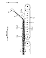
- the suction belt conveyor 70 has an endless net 72 (corresponding to a support member) that drives around a circulation track.
- the orbit has a flat path along the horizontal direction.
- a suction box 74 is disposed inside the orbit of the net 72, and an intake port 74k is sucking air at an upper portion of the box 74, whereby a suction force is applied to the upper surface 72s of the net 72. Has occurred.
- the melt-spun fiber f is discharged from the nozzle 76 disposed above the upper surface 72 s of the net 72 toward the flat path, the fiber f is sucked by the upper surface 72 s of the net 72.
- the nonwoven fabric 1NW is generally formed.
- the fibers f are deposited on the upper surface 72s of the net 72, a large suction force acts in the vicinity of the upper surface 72s, but the suction force decreases as the distance from the upper surface 72s increases. For this reason, the density of the fibers f increases on the upper surface 72s of the net 72, and the fibers f and f are bonded with a high bond strength.
- the density of the fibers f decreases as the distance from the upper surface 72s increases. As a result, the bonding strength between the fibers f and f becomes small. Therefore, the non-contact surface 1NWs2 that does not contact is smaller than the contact surface 1NWs1 that contacts the upper surface 72s of the net 72 among the both surfaces 1NWs1 and 1NWs2 of the nonwoven fabric 1NW, and the bonding strength between the fibers f and f is smaller. Become.
- the building 12 on the entire second floor is exemplified as the building 12 of the absorbent article manufacturing factory 10, but the present invention is not limited thereto. That is, it may be more than 3 floors.
- the upper and lower floors are not limited to the second and first floors, but may be the third and second floors, or the fourth and third floors.
- the 2nd floor building is not limited to the 2nd floor above all. That is, the entire two-story building may be composed of a basement floor and a ground floor.
- the first floor and the second floor are each surrounded by four wall portions 14d, 14d,..., 14u,.
- 14u includes not only solid wall portions such as RC structures, wooden structures, metal plates, etc., but also wall portions formed of gas such as so-called air curtains that create curtains of airflow.
- the rectangular shape is illustrated as an example of the planar shape of the floor portions 13d and 13u on the first floor and the second floor, but the present invention is not limited thereto.
- it may be a polygon such as a hexagon or a circle.
- it may be a planar shape having an entrance corner or an exit corner.
- a wall portion is provided corresponding to each side of the planar shape.
- the feeding direction of the nonwoven fabric 1NW of each feeding device 30 provided in the feeding area A30 on the second floor is along the X direction.
- the planar shape is a substantially rectangular shape whose longitudinal direction is along the Y direction, but is not limited thereto.
- the planar shape of the communication opening 13uk corresponding to the device 30 is made a substantially rectangular shape whose longitudinal direction is along the X direction. May be.
- the planar shape of the communication opening 13uk may be a polygonal shape other than a quadrangle or a circular shape such as an ellipse, or more specifically, a combined shape combining straight lines and curves. good.
Landscapes
- Health & Medical Sciences (AREA)
- Engineering & Computer Science (AREA)
- Life Sciences & Earth Sciences (AREA)
- General Health & Medical Sciences (AREA)
- Public Health (AREA)
- Veterinary Medicine (AREA)
- Epidemiology (AREA)
- Biomedical Technology (AREA)
- Heart & Thoracic Surgery (AREA)
- Vascular Medicine (AREA)
- Animal Behavior & Ethology (AREA)
- Architecture (AREA)
- Manufacturing & Machinery (AREA)
- Civil Engineering (AREA)
- Structural Engineering (AREA)
- Botany (AREA)
- Nonwoven Fabrics (AREA)
- Absorbent Articles And Supports Therefor (AREA)
- Treatment Of Fiber Materials (AREA)
Abstract
L'invention concerne une usine de fabrication (10) qui fabrique des articles absorbants. L'usine de fabrication (10) comprend un bâtiment (12) possédant : un étage supérieur possédant un plancher (13u), des parois (14u) disposées le long de la périphérie entière du plancher (13u), un équipement d'éclairage disposé sur le plafond et un climatiseur avec une sortie d'air ; et un étage inférieur possédant un plancher (13d), des parois (14d) disposées le long de la périphérie entière du plancher (13d), un équipement d'éclairage disposé sur le plafond et un climatiseur avec une sortie d'air. Une ouverture (13uk) qui permet la communication entre l'étage supérieur et l'étage inférieur est formée sur le plancher (13u) de l'étage supérieur. Un dispositif de distribution (30) qui a une bobine de matériau (1CNW) enroulée avec un tissu non tissé (1NW) fixé à celui-ci et qui distribue le tissu non tissé (1NW) est disposé sur l'étage supérieur. Une partie de traitement (20) qui traite une pluralité de types de matériaux (1) comprenant le tissu non tissé (1NW) délivré depuis l'étage supérieur à travers l'ouverture (13uk) est disposée sur l'étage inférieur.
Priority Applications (5)
| Application Number | Priority Date | Filing Date | Title |
|---|---|---|---|
| JP2017518165A JP6171119B1 (ja) | 2016-12-16 | 2016-12-16 | 吸収性物品の製造工場 |
| PCT/JP2016/087640 WO2018109941A1 (fr) | 2016-12-16 | 2016-12-16 | Usine de fabrication d'articles absorbants |
| US16/465,821 US10822826B2 (en) | 2016-12-16 | 2016-12-16 | Factory for manufacturing absorbent article |
| CN201680091614.2A CN110087596B (zh) | 2016-12-16 | 2016-12-16 | 吸收性物品的制造工厂 |
| EP16923698.1A EP3556332B1 (fr) | 2016-12-16 | 2016-12-16 | Usine de fabrication d'articles absorbants |
Applications Claiming Priority (1)
| Application Number | Priority Date | Filing Date | Title |
|---|---|---|---|
| PCT/JP2016/087640 WO2018109941A1 (fr) | 2016-12-16 | 2016-12-16 | Usine de fabrication d'articles absorbants |
Publications (1)
| Publication Number | Publication Date |
|---|---|
| WO2018109941A1 true WO2018109941A1 (fr) | 2018-06-21 |
Family
ID=59384347
Family Applications (1)
| Application Number | Title | Priority Date | Filing Date |
|---|---|---|---|
| PCT/JP2016/087640 Ceased WO2018109941A1 (fr) | 2016-12-16 | 2016-12-16 | Usine de fabrication d'articles absorbants |
Country Status (5)
| Country | Link |
|---|---|
| US (1) | US10822826B2 (fr) |
| EP (1) | EP3556332B1 (fr) |
| JP (1) | JP6171119B1 (fr) |
| CN (1) | CN110087596B (fr) |
| WO (1) | WO2018109941A1 (fr) |
Families Citing this family (3)
| Publication number | Priority date | Publication date | Assignee | Title |
|---|---|---|---|---|
| JP7375455B2 (ja) * | 2019-10-18 | 2023-11-08 | 王子ホールディングス株式会社 | 吸収性物品の製造装置及び製造工場 |
| CN111894314A (zh) * | 2020-07-06 | 2020-11-06 | 北新集团建材股份有限公司 | 一种纸面石膏板高速锯切边降噪房 |
| WO2026025485A1 (fr) * | 2024-08-02 | 2026-02-05 | 金伯利-克拉克环球有限公司 | Dispositif et procédé destinés à fournir en continu un stratifié élastomère à une chaîne de production |
Citations (2)
| Publication number | Priority date | Publication date | Assignee | Title |
|---|---|---|---|---|
| JP2000201958A (ja) * | 1998-08-25 | 2000-07-25 | Winkler & Duennebier Ag | 多層衛生製品を製造するための方法および装置 |
| EP2491909A1 (fr) | 2011-02-25 | 2012-08-29 | Curt G. Joa, Inc. | Procédés et appareil de formation de produits jetables à grande vitesse avec une petite empreinte de machine |
Family Cites Families (11)
| Publication number | Priority date | Publication date | Assignee | Title |
|---|---|---|---|---|
| US4048769A (en) * | 1973-02-09 | 1977-09-20 | Lely Cornelis V D | Buildings formed by one or more prefabricated building sections, and method of manufacturing prefabricated building sections |
| US4136492A (en) * | 1973-06-04 | 1979-01-30 | Willingham John H | Industrialized building construction |
| US3984272A (en) * | 1974-07-25 | 1976-10-05 | Riegel Textile Corporation | Method and apparatus for successively forming disposable diapers |
| US4331501A (en) * | 1979-06-06 | 1982-05-25 | Riegel Textile Corporation | Apparatus and process for successively fabricating disposable diapers having multi-layer interior absorbent pads |
| US4783231A (en) * | 1985-10-07 | 1988-11-08 | Kimberly-Clark Corporation | Method of making a fibrous web comprising differentially cooled/thermally relaxed fibers |
| US7638014B2 (en) * | 2004-05-21 | 2009-12-29 | Curt G. Joa, Inc. | Method of producing a pants-type diaper |
| CA2724938C (fr) * | 2009-12-18 | 2017-01-24 | Fluor Technologies Corporation | Installation de traitement modulaire |
| CN103649443B (zh) * | 2011-06-28 | 2017-06-23 | 帝斯曼知识产权资产管理有限公司 | 模块多层生产设备及其构造方法 |
| CN102579198B (zh) * | 2012-02-20 | 2014-06-18 | 福建益川自动化设备股份公司 | 一种生产简易训练裤的方法及其加工装置 |
| CN204322514U (zh) * | 2014-10-28 | 2015-05-13 | 杭州珂瑞特机械制造有限公司 | 全伺服柔软婴儿拉拉裤生产线 |
| CN205662683U (zh) * | 2016-06-03 | 2016-10-26 | 佛山市格菲林卫材科技有限公司 | 超柔疏水无纺布的生产系统 |
-
2016
- 2016-12-16 EP EP16923698.1A patent/EP3556332B1/fr active Active
- 2016-12-16 CN CN201680091614.2A patent/CN110087596B/zh active Active
- 2016-12-16 US US16/465,821 patent/US10822826B2/en not_active Expired - Fee Related
- 2016-12-16 JP JP2017518165A patent/JP6171119B1/ja active Active
- 2016-12-16 WO PCT/JP2016/087640 patent/WO2018109941A1/fr not_active Ceased
Patent Citations (2)
| Publication number | Priority date | Publication date | Assignee | Title |
|---|---|---|---|---|
| JP2000201958A (ja) * | 1998-08-25 | 2000-07-25 | Winkler & Duennebier Ag | 多層衛生製品を製造するための方法および装置 |
| EP2491909A1 (fr) | 2011-02-25 | 2012-08-29 | Curt G. Joa, Inc. | Procédés et appareil de formation de produits jetables à grande vitesse avec une petite empreinte de machine |
Also Published As
| Publication number | Publication date |
|---|---|
| JP6171119B1 (ja) | 2017-07-26 |
| CN110087596B (zh) | 2021-10-26 |
| EP3556332B1 (fr) | 2021-08-04 |
| US10822826B2 (en) | 2020-11-03 |
| CN110087596A (zh) | 2019-08-02 |
| JPWO2018109941A1 (ja) | 2018-12-13 |
| EP3556332A1 (fr) | 2019-10-23 |
| EP3556332A4 (fr) | 2019-12-25 |
| US20190301190A1 (en) | 2019-10-03 |
Similar Documents
| Publication | Publication Date | Title |
|---|---|---|
| US7094373B2 (en) | Process and apparatus for air forming an article having a plurality of reinforced superimposed fibrous layers | |
| JP5261604B2 (ja) | 積繊装置 | |
| JP6269181B2 (ja) | シート製造装置 | |
| JP6287365B2 (ja) | シート製造装置 | |
| JP6171119B1 (ja) | 吸収性物品の製造工場 | |
| JP4271580B2 (ja) | 補強繊維性吸収部材を製造する方法及び装置 | |
| CN104837447B (zh) | 积纤体的制造方法 | |
| US20120056347A1 (en) | Manufacturing method and a manufacturing apparatus for a composite sheet | |
| JP2016098473A (ja) | シート製造装置 | |
| JP2001171029A (ja) | 粒子堆積体の製造方法 | |
| US9776213B2 (en) | Sheet manufacturing apparatus | |
| US11767622B2 (en) | Methods of creating soft and lofty nonwoven webs | |
| US10076897B2 (en) | Method and apparatus for producing a granular powder-containing sheet | |
| JP2017046928A (ja) | 吸収体の製造方法 | |
| JPWO2014104322A1 (ja) | 清掃部材を製造する方法及びシステム | |
| JP4445396B2 (ja) | 複合吸収材製品、その製造方法および装置 | |
| US20160228301A1 (en) | Absorbent article manufacturing apparatus and method for modifying manufacturing apparatus | |
| JP2804486B2 (ja) | パッド製品形成装置及びパッドを形成する方法 | |
| US9903058B2 (en) | Absorbent article manufacturing apparatus and absorbent article manufacturing method | |
| JP4141096B2 (ja) | 積層フィルムの分離装置 | |
| JP7253769B2 (ja) | 積層シート体の製造装置 | |
| US20150176205A1 (en) | Sheet manufacturing apparatus | |
| JP7375455B2 (ja) | 吸収性物品の製造装置及び製造工場 | |
| WO2004028426A1 (fr) | Procede et appareil de formage a l'air d'un article ayant une pluralite de couches fibreuses superposees renforcees | |
| TR2022015091A2 (tr) | Radyal besleme si̇stemi̇ i̇le hizli koli̇leme |
Legal Events
| Date | Code | Title | Description |
|---|---|---|---|
| ENP | Entry into the national phase |
Ref document number: 2017518165 Country of ref document: JP Kind code of ref document: A |
|
| 121 | Ep: the epo has been informed by wipo that ep was designated in this application |
Ref document number: 16923698 Country of ref document: EP Kind code of ref document: A1 |
|
| NENP | Non-entry into the national phase |
Ref country code: DE |
|
| ENP | Entry into the national phase |
Ref document number: 2016923698 Country of ref document: EP Effective date: 20190716 |