WO2018110102A1 - Gabarit de transport - Google Patents
Gabarit de transport Download PDFInfo
- Publication number
- WO2018110102A1 WO2018110102A1 PCT/JP2017/038585 JP2017038585W WO2018110102A1 WO 2018110102 A1 WO2018110102 A1 WO 2018110102A1 JP 2017038585 W JP2017038585 W JP 2017038585W WO 2018110102 A1 WO2018110102 A1 WO 2018110102A1
- Authority
- WO
- WIPO (PCT)
- Prior art keywords
- frame
- frame member
- jig
- stringer
- conveying jig
- Prior art date
- Legal status (The legal status is an assumption and is not a legal conclusion. Google has not performed a legal analysis and makes no representation as to the accuracy of the status listed.)
- Ceased
Links
Images



Classifications
-
- A—HUMAN NECESSITIES
- A47—FURNITURE; DOMESTIC ARTICLES OR APPLIANCES; COFFEE MILLS; SPICE MILLS; SUCTION CLEANERS IN GENERAL
- A47B—TABLES; DESKS; OFFICE FURNITURE; CABINETS; DRAWERS; GENERAL DETAILS OF FURNITURE
- A47B81/00—Cabinets or racks specially adapted for other particular purposes, e.g. for storing guns or skis
-
- B—PERFORMING OPERATIONS; TRANSPORTING
- B64—AIRCRAFT; AVIATION; COSMONAUTICS
- B64F—GROUND OR AIRCRAFT-CARRIER-DECK INSTALLATIONS SPECIALLY ADAPTED FOR USE IN CONNECTION WITH AIRCRAFT; DESIGNING, MANUFACTURING, ASSEMBLING, CLEANING, MAINTAINING OR REPAIRING AIRCRAFT, NOT OTHERWISE PROVIDED FOR; HANDLING, TRANSPORTING, TESTING OR INSPECTING AIRCRAFT COMPONENTS, NOT OTHERWISE PROVIDED FOR
- B64F5/00—Designing, manufacturing, assembling, cleaning, maintaining or repairing aircraft, not otherwise provided for; Handling, transporting, testing or inspecting aircraft components, not otherwise provided for
- B64F5/10—Manufacturing or assembling aircraft, e.g. jigs therefor
-
- A—HUMAN NECESSITIES
- A47—FURNITURE; DOMESTIC ARTICLES OR APPLIANCES; COFFEE MILLS; SPICE MILLS; SUCTION CLEANERS IN GENERAL
- A47B—TABLES; DESKS; OFFICE FURNITURE; CABINETS; DRAWERS; GENERAL DETAILS OF FURNITURE
- A47B81/00—Cabinets or racks specially adapted for other particular purposes, e.g. for storing guns or skis
- A47B81/005—Devices for storing or displaying rifles, guns, pistols or elongated objects such as fishing rods storing fishing rods
-
- B—PERFORMING OPERATIONS; TRANSPORTING
- B62—LAND VEHICLES FOR TRAVELLING OTHERWISE THAN ON RAILS
- B62B—HAND-PROPELLED VEHICLES, e.g. HAND CARTS OR PERAMBULATORS; SLEDGES
- B62B3/00—Hand carts having more than one axis carrying transport wheels; Steering devices therefor; Equipment therefor
- B62B3/02—Hand carts having more than one axis carrying transport wheels; Steering devices therefor; Equipment therefor involving parts being adjustable, collapsible, attachable, detachable or convertible
-
- B—PERFORMING OPERATIONS; TRANSPORTING
- B62—LAND VEHICLES FOR TRAVELLING OTHERWISE THAN ON RAILS
- B62B—HAND-PROPELLED VEHICLES, e.g. HAND CARTS OR PERAMBULATORS; SLEDGES
- B62B3/00—Hand carts having more than one axis carrying transport wheels; Steering devices therefor; Equipment therefor
- B62B3/10—Hand carts having more than one axis carrying transport wheels; Steering devices therefor; Equipment therefor characterised by supports specially adapted to objects of definite shape
- B62B3/102—Hand carts having more than one axis carrying transport wheels; Steering devices therefor; Equipment therefor characterised by supports specially adapted to objects of definite shape the objects being of elongated shape, e.g. rods or golf clubs
-
- B—PERFORMING OPERATIONS; TRANSPORTING
- B64—AIRCRAFT; AVIATION; COSMONAUTICS
- B64F—GROUND OR AIRCRAFT-CARRIER-DECK INSTALLATIONS SPECIALLY ADAPTED FOR USE IN CONNECTION WITH AIRCRAFT; DESIGNING, MANUFACTURING, ASSEMBLING, CLEANING, MAINTAINING OR REPAIRING AIRCRAFT, NOT OTHERWISE PROVIDED FOR; HANDLING, TRANSPORTING, TESTING OR INSPECTING AIRCRAFT COMPONENTS, NOT OTHERWISE PROVIDED FOR
- B64F5/00—Designing, manufacturing, assembling, cleaning, maintaining or repairing aircraft, not otherwise provided for; Handling, transporting, testing or inspecting aircraft components, not otherwise provided for
- B64F5/50—Handling or transporting aircraft components
-
- B—PERFORMING OPERATIONS; TRANSPORTING
- B65—CONVEYING; PACKING; STORING; HANDLING THIN OR FILAMENTARY MATERIAL
- B65D—CONTAINERS FOR STORAGE OR TRANSPORT OF ARTICLES OR MATERIALS, e.g. BAGS, BARRELS, BOTTLES, BOXES, CANS, CARTONS, CRATES, DRUMS, JARS, TANKS, HOPPERS, FORWARDING CONTAINERS; ACCESSORIES, CLOSURES, OR FITTINGS THEREFOR; PACKAGING ELEMENTS; PACKAGES
- B65D19/00—Pallets or like platforms, with or without side walls, for supporting loads to be lifted or lowered
- B65D19/38—Details or accessories
- B65D19/40—Elements for spacing platforms from supporting surface
- B65D19/42—Arrangements or applications of rollers or wheels
-
- B—PERFORMING OPERATIONS; TRANSPORTING
- B65—CONVEYING; PACKING; STORING; HANDLING THIN OR FILAMENTARY MATERIAL
- B65G—TRANSPORT OR STORAGE DEVICES, e.g. CONVEYORS FOR LOADING OR TIPPING, SHOP CONVEYOR SYSTEMS OR PNEUMATIC TUBE CONVEYORS
- B65G7/00—Devices for assisting manual moving or tilting heavy loads
- B65G7/02—Devices adapted to be interposed between loads and the ground or floor, e.g. crowbars with means for assisting conveyance of loads
- B65G7/08—Devices adapted to be interposed between loads and the ground or floor, e.g. crowbars with means for assisting conveyance of loads for tilting the loads
-
- B—PERFORMING OPERATIONS; TRANSPORTING
- B62—LAND VEHICLES FOR TRAVELLING OTHERWISE THAN ON RAILS
- B62B—HAND-PROPELLED VEHICLES, e.g. HAND CARTS OR PERAMBULATORS; SLEDGES
- B62B2203/00—Grasping, holding, supporting the objects
- B62B2203/05—Rocking means for facilitating tilting of the cart, e.g. by loading
-
- B—PERFORMING OPERATIONS; TRANSPORTING
- B62—LAND VEHICLES FOR TRAVELLING OTHERWISE THAN ON RAILS
- B62B—HAND-PROPELLED VEHICLES, e.g. HAND CARTS OR PERAMBULATORS; SLEDGES
- B62B2206/00—Adjustable or convertible hand-propelled vehicles or sledges
- B62B2206/003—Adjustable or convertible hand-propelled vehicles or sledges with actuation mechanisms which drive the adjustment or conversion operation
-
- B—PERFORMING OPERATIONS; TRANSPORTING
- B64—AIRCRAFT; AVIATION; COSMONAUTICS
- B64C—AEROPLANES; HELICOPTERS
- B64C1/00—Fuselages; Constructional features common to fuselages, wings, stabilising surfaces or the like
- B64C1/06—Frames; Stringers; Longerons ; Fuselage sections
- B64C1/061—Frames
-
- B—PERFORMING OPERATIONS; TRANSPORTING
- B64—AIRCRAFT; AVIATION; COSMONAUTICS
- B64C—AEROPLANES; HELICOPTERS
- B64C1/00—Fuselages; Constructional features common to fuselages, wings, stabilising surfaces or the like
- B64C1/06—Frames; Stringers; Longerons ; Fuselage sections
- B64C1/064—Stringers; Longerons
Definitions
- the present invention relates to a conveying jig, and particularly to a conveying jig that accommodates a long member constituting an aircraft part.
- Aircraft parts such as the fuselage and the main wing are composed of a skin that is a plate-like member and a plurality of members such as a frame and a stringer that are elongated members.
- the skin When the aircraft part is a fuselage, the skin has an arc shape in a cross section cut perpendicularly to the aircraft axis direction.
- the frame is an elongated member disposed along the circumference of the skin, has an arc shape, and has a curvature.
- the stringer is a member arranged in parallel to the aircraft axis direction with respect to the skin, and is a substantially straight long member.
- An aircraft part such as a fuselage is manufactured by attaching a frame or a stringer to the skin.
- the aircraft fuselage has a circular cross section, and the diameter of the circular shape changes along the axial direction. Therefore, skins, frames, and stringers have a wide variety of three-dimensional shapes. Further, each member such as the skin, the frame, and the stringer is reduced in weight and has low rigidity.
- Patent Document 1 discloses an invention relating to a transport tool for transporting a large composite aircraft fuselage part, and discloses a technique in which the transport tool supports, positions, and transports the fuselage part.
- each member constituting an aircraft part such as a fuselage has a feature of being long, low-rigidity, various types, and a three-dimensional shape. Therefore, it is difficult to handle each member, and it is difficult to transport each member to an assembly work place or the like. Moreover, if the conveyance work of each member can be performed efficiently, the unmanned rate in the factory can be improved, but each member has the above-described long shape, low rigidity, various types, and a three-dimensional shape. It is required to overcome this feature.
- the present invention has been made in view of such circumstances, and can easily transport a plurality of long members and access the plurality of long members in the same direction.
- An object of the present invention is to provide a conveying jig that can be used.
- the conveyance jig which concerns on 1 aspect of this invention is equipped with a frame material and the support part which is installed in the said frame material, and supports several elongate member,
- the said elongate member is the said over the full length.
- the support portion Housed inside the frame member, the support portion supports the plurality of long members in parallel in the same direction.
- the support portion is installed on the frame member and supports a plurality of long members. Moreover, since a plurality of elongate members are accommodated inside the frame material, the frame material becomes the outermost peripheral portion of the conveying jig. Further, the plurality of long members are supported in parallel in the same direction by the support portion, and the plurality of long members can be accessed in the same direction from the outside of the frame member. Therefore, when applying or processing a seal on the same surface of each long member, it is not necessary to change the access direction for each long member, so that the work efficiency is good. It is also easy to take out the long member housed inside the frame material to the outside of the frame material.
- the support portion may have a configuration corresponding to the shape of the elongated member to be accommodated, and is detachable from the frame member.
- the support portion has a configuration corresponding to the shape of the elongated member, and can be attached to and detached from the frame member. Therefore, by replacing the support portion, a plurality of types having different shapes can be obtained.
- the long member can be accommodated in the frame member.
- the frame member is installed in a first direction in which the surface on which the sealing material is applied or the surface on which the processing is applied in the elongated member can be set upward, and the first member Unlike the direction of 1, it may have the state installed in the 2nd direction in which the elongate member accommodated in the frame material can be taken out of the frame material.
- the frame member when the frame member is in the first direction, the surface on which the sealing material is applied or the surface on which the processing is applied in the long member can be directed upward, and the frame member is in the second direction. In this direction, the long member accommodated in the frame material can be taken out of the frame material.
- the change between the first direction and the second direction may be performed by driving a jack provided on the frame member.
- the direction of the frame member can be changed between the first direction and the second direction by driving the jack.
- a wheel installed on the frame member may be further provided.
- the conveying jig can be moved by the wheels installed on the frame member.
- a plurality of long members can be easily transported, and the plurality of long members can be accessed in the same direction.
- the conveyance jig 1 accommodates a plurality of long members for constituting an aircraft part, and can convey the plurality of long members in a lump.
- the long member is, for example, a frame having an arc shape constituting an aircraft part (fuselage, main wing, etc.).
- tool 1 for conveyance accommodates the flame
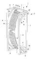
- the conveying jig 1 includes a frame member 3 and a support portion 4 installed on the frame member 3.
- the frame member 3 has, for example, a rectangular parallelepiped shape, and a rod-shaped member that constitutes the frame member 3 is disposed in a portion corresponding to a side of the rectangular parallelepiped.
- the frame member 3 is configured by combining a plurality of rod-shaped members.
- the rod-shaped member of the frame member 3 includes, for example, four first members 7 that form a quadrangle, four second members 8 that are installed perpendicular to the first member 7 and are parallel to each other, and a second member.
- the frame 51 is accommodated inside the frame material 3 over its entire length. That is, the frame member 3 is configured such that the frame member 3 becomes the outermost peripheral portion of the transfer jig 1 when a plurality of frames 51 are accommodated inside the transfer jig 1.
- a table transfer jig 1 can be arranged. Therefore, stored items such as the conveying jig 1 and the frame 51 can be stored in a predetermined place in an orderly manner.
- the support portion 4 is installed on the frame member 3 inside the frame member 3. That is, the support part 4 is accommodated inside the frame member 3, and the frame member 3 is configured to be the outermost peripheral part of the conveying jig 1.
- the support unit 4 supports a plurality of frames 51 in parallel in the same direction.
- the support part 4 is installed in the 1st base part 11, the 2nd base part 12 which has the circular arc shape along the shape of the flame
- frame 51 for example, the 1st base part 11 connected to the 1st member 7 in both ends. And a clamp (not shown) for holding the frame 51.
- the first platform 11 is installed, for example, in the vicinity of the longitudinal end of the frame member 3, and a plurality of second platforms 12 are installed in parallel between the two first platforms 11.
- One frame 51 can be installed on one second platform 12, and the number of installations of the second platform 12 is determined according to the number of frames 51 accommodated in the transfer jig 1.
- the shape of the support portion 4, that is, the shape of the first base portion 11 and the second base portion 12 or a combination of both has a configuration corresponding to the shape of the frame 51 to be accommodated, and is detachable from the frame material 3. is there. Therefore, by replacing the support part 4, it is possible to accommodate a plurality of types of frames 51 having different shapes in the frame member 3.
- the clamp is fixed to the first base part 11 or the second base part 12 and holds one frame 51.
- the clamp is disposed at a position corresponding to an end portion or an intermediate portion of the frame 51 placed on the second base portion 12.
- the number of clamps installed on the first base part 11 and the second base part 12 is determined according to the length and shape of the frame 51.
- the conveying jig 1 can easily apply a sealing material to the accommodated frame 51 as shown in FIG. 1, or the conveying jig 1 as shown in FIG.
- the frame 51 is configured to be easily taken out from the inside of the tool 1 to the outside.
- a sealing material is applied to the frame 51.
- the present invention is not limited to this example, and a hole is formed in a long member such as the frame 51 accommodated in the conveying jig 1. Mechanical processing such as dawn may be performed.
- the wheel 20 is installed in the frame material 3 of the jig 1 for conveyance, and when the jig 1 for conveyance is installed in the 1st direction mentioned later.
- the conveying jig 1 can be moved by the wheel 20.
- tool 1 for conveyance moves to a working place from a storage place or between different working places, for example.
- the conveyance jig 1 is not limited to the case where the wheels 20 are previously installed on the frame member 3.
- the conveyance jig 1 is placed on a carriage (not shown), and the conveyance jig 1 is moved by the carriage. It may be movable.
- a sealing material is applied to the outer peripheral surface of the frame 51 facing the skin.
- the sealing material By applying the sealing material to the frame 51, the skin and the frame 51 are brought into close contact with the sealing material.
- the outer peripheral surface of the frame 51 that is, the coating surface faces upward, and the plurality of frames 51 are arranged in parallel in the same direction inside the frame member 3. Therefore, the worker or the working robot can access the plurality of frames 51 from the outside of the frame member 3 in the same direction. Therefore, when applying a seal to the same surface of each frame 51, it is not necessary to change the access direction for each frame 51, so that work efficiency is good.
- the frame 51 In the step of installing the frame 51 on the skin, it is desirable that the frame 51 is transported so that the strings connecting both ends are in the vertical direction.
- the conveying jig 1 When the conveying jig 1 is installed in the second direction, the frame 51 has a string connecting both ends in the vertical direction inside the frame member 3, and the plurality of frames 51 are arranged in parallel in the same direction. Are arranged. Therefore, when the worker or the working robot takes out the frame 51 from the conveying jig 1 and conveys it to the place where it is installed with respect to the skin, the worker or the working robot can convey the frame 51 with almost no change in the orientation of the frame 51. it can.
- tool 1 for conveyance is performed using weighting apparatuses, such as a chain block, for example.
- weighting apparatuses such as a chain block
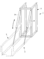
- FIG. 3 by installing a jack 21 on the frame 3 of the conveying jig 1 and driving the jack 21, the first direction of the conveying jig 1 and the second direction The direction may be changed.
- the transfer jig 1 indicated by the solid line is installed in the second direction, and the transfer jig 1 indicated by the two-dot chain line is installed in the first direction. is there.
- the support portion 4 and the frame 51 are omitted.
- the conveying jig 1 may have a configuration in which the jack 21 is attached to the frame member 3 when the direction is changed, or the jack 21 is always installed on the frame member 3 even when the direction is not changed. You may make it have a structure.
- the conveying jig 2 accommodates a plurality of long members therein and can convey the plurality of long members together.
- the elongated member is, for example, a stringer having a substantially linear shape that constitutes an aircraft part (fuselage, main wing, etc.).
- tool 1 for conveyance accommodates the stringer 52 is demonstrated.
- the conveying jig 2 includes a frame member 5 and a support portion 6 installed on the frame member 5.
- the frame member 5 has, for example, a quadrangular shape, and a rod-shaped member that constitutes the frame member 5 is disposed in a portion corresponding to the side of the quadrangle.
- the frame member 5 is configured by combining a plurality of rod-shaped members.
- the rod-shaped member of the frame member 5 includes, for example, one first member 13 that forms a long side of a quadrangle, and three second members 14 that are installed perpendicular to the first member 13 and are parallel to each other. .
- An end portion of the second member 14 is connected to an end portion of the first member 13 or an intermediate portion of the first member 13.
- the stringer 52 is accommodated inside the frame material 5 over the entire length. That is, the frame member 5 is configured such that the frame member 5 becomes the outermost peripheral portion of the transfer jig 2 when a plurality of stringers 52 are accommodated inside the transfer jig 2. As a result, even when a plurality of transfer jigs 2 are arranged in a factory or the like, a plurality of transfer jigs 2 can be arranged adjacent to each other without being interfered with by the accommodation such as the stringer 52. . Therefore, stored items such as the conveying jig 2 and the stringer 52 can be stored in a predetermined place in an orderly manner.
- the support unit 6 supports a plurality of stringers 52 in parallel in the same direction.
- the support part 6 includes, for example, a base part 15 installed on the second member 14 and a clamp (not shown) that is installed on the base part 15 and grips the stringer 52.
- a plurality of stringers 52 are installed in parallel on the platform 15.
- the number of installations of the platform 15 is determined according to the number of stringers 52 accommodated in the conveying jig 2.
- the clamp is fixed to the base 15 and holds one stringer 52.
- the clamp is disposed at a position corresponding to an end portion or an intermediate portion of the stringer 52 placed on the base portion 15.
- the number of clamps installed in the conveying jig 2 is determined according to the length, shape, and the like of the stringer 52. Therefore, the number of second members 14 of the frame member 5 is also changed according to the number of clamps.
- the sealing material can be easily applied to the accommodated stringer 52 as shown in FIG. 4, or as shown in FIG.
- the stringer 52 can be easily taken out from the inside of the tool 2 to the outside.
- a sealing material is applied to the stringer 52 will be described.
- the present invention is not limited to this example, and a hole is formed in a long member such as the stringer 52 accommodated in the conveying jig 2. Mechanical processing such as dawn may be performed.
- the transfer jig 2 is installed on a carriage (not shown), for example, or supported at both ends by two workers, for example, from a storage place to a work place or a different work place. Move between. Note that wheels may be provided in advance on the frame material 5 of the conveying jig 2 so that the conveying jig 2 can be moved by the wheels.
- a sealing material is applied to the outer surface of the stringer 52 facing the skin.
- a sealing material is applied to the stringer 52, the skin and the stringer 52 are brought into close contact with each other by the sealing material.
- the outer surface of the stringer 52 that is, the application surface faces upward, and the plurality of stringers 52 are arranged in parallel in the same direction inside the frame member 5. Therefore, the worker or the working robot can access the plurality of stringers 52 from the outside of the frame member 5 in the same direction. Therefore, when applying a seal to the same surface of each stringer, it is not necessary to change the access direction for each stringer 52, so that the working efficiency is good.
- the axial direction of the base portion 15 is a vertical direction.
- the conveying jig 2 is installed in the second direction and the stringer 52 is disposed along the base portion 15, the outer surface of the stringer 52 is located on the side surface side of the conveying jig 2. .
- the stringer 52 is conveyed so that the surface on which the sealing material is applied is parallel to the surface of the skin, that is, the seal application surface is substantially vertical. Is desirable.
- the conveying jig 2 is installed in the second direction, the stringer 52 is placed inside the frame member 5 so that the seal application surface is vertical, and a plurality of stringers 52 are arranged in parallel in the same direction. Has been. Therefore, when the worker or the working robot takes out the stringer 52 from the transport jig 2 and transports the stringer 52 to the place where it is installed with respect to the skin, the worker or the work robot can transport the stringer 52 without changing the orientation of the stringer 52. it can.
- tool 2 for conveyance is performed using a hoisting device, such as a chain block, for example.
- a hoisting device such as a chain block
- the jack 22 is installed on the frame member 5 of the transport jig 2 and the jack 22 is driven, whereby the first direction and the second direction of the transport jig 2 are set.
- the direction may be changed.
- the transfer jig 2 indicated by the solid line is installed in the second direction, and the transfer jig 2 indicated by the two-dot chain line is installed in the first direction. is there.
- the stringer 52 and the like are omitted.
- the conveying jig 2 may have a configuration in which the jack 22 is attached to the frame member 5 when the direction is changed, or the jack 22 is always installed on the frame member 5 even when the direction is not changed. You may make it have a structure.
- Transfer jig 2 Transfer jig 3: Frame material 4: Support portion 5: Frame material 6: Support portion 7: First member 8: Second member 9: Third member 10: Diagonal material 11: First 1 stand 12: 2nd stand 13: 1st member 14: 2nd member 15: stand 21: jack 22: jack 51: frame 52: stringer
Landscapes
- Engineering & Computer Science (AREA)
- Transportation (AREA)
- Manufacturing & Machinery (AREA)
- Mechanical Engineering (AREA)
- Chemical & Material Sciences (AREA)
- Combustion & Propulsion (AREA)
- Aviation & Aerospace Engineering (AREA)
- Automatic Assembly (AREA)
- Packaging Of Annular Or Rod-Shaped Articles, Wearing Apparel, Cassettes, Or The Like (AREA)
- Pallets (AREA)
Abstract
Priority Applications (3)
| Application Number | Priority Date | Filing Date | Title |
|---|---|---|---|
| JP2018556232A JP6804558B2 (ja) | 2016-12-13 | 2017-10-25 | 搬送用治具 |
| CA3046421A CA3046421A1 (fr) | 2016-12-13 | 2017-10-25 | Gabarit de transport |
| US16/467,714 US11066187B2 (en) | 2016-12-13 | 2017-10-25 | Transport jig |
Applications Claiming Priority (2)
| Application Number | Priority Date | Filing Date | Title |
|---|---|---|---|
| JP2016241048 | 2016-12-13 | ||
| JP2016-241048 | 2016-12-13 |
Publications (1)
| Publication Number | Publication Date |
|---|---|
| WO2018110102A1 true WO2018110102A1 (fr) | 2018-06-21 |
Family
ID=62558496
Family Applications (1)
| Application Number | Title | Priority Date | Filing Date |
|---|---|---|---|
| PCT/JP2017/038585 Ceased WO2018110102A1 (fr) | 2016-12-13 | 2017-10-25 | Gabarit de transport |
Country Status (4)
| Country | Link |
|---|---|
| US (1) | US11066187B2 (fr) |
| JP (1) | JP6804558B2 (fr) |
| CA (1) | CA3046421A1 (fr) |
| WO (1) | WO2018110102A1 (fr) |
Citations (3)
| Publication number | Priority date | Publication date | Assignee | Title |
|---|---|---|---|---|
| JPS57149220U (fr) * | 1981-03-16 | 1982-09-18 | ||
| JPH08169343A (ja) * | 1994-12-16 | 1996-07-02 | Fujita Corp | 起立機構付き台車 |
| JP2012218780A (ja) * | 2011-04-08 | 2012-11-12 | Sekisui House Ltd | ブレース搬送用パレット及び長手材搬送用パレット |
Family Cites Families (28)
| Publication number | Priority date | Publication date | Assignee | Title |
|---|---|---|---|---|
| US3147860A (en) * | 1961-03-24 | 1964-09-08 | Libbey Owens Ford Glass Co | Shipping apparatus for sheets or plates |
| US3499398A (en) * | 1968-05-02 | 1970-03-10 | Cerco Corp | Portable storage rack or pallet |
| US3557855A (en) * | 1969-03-07 | 1971-01-26 | Us Air Force | Pallet having hinged end panels and flexible cover members |
| US3809234A (en) * | 1971-11-08 | 1974-05-07 | Libbey Owens Ford Co | Glass shipping rack |
| DE3435941A1 (de) * | 1984-09-29 | 1986-04-10 | Karl 6096 Raunheim Gerlach | Stapelbehaelter fuer formteile, insbesondere blechstanzteile |
| US4919277A (en) * | 1989-03-20 | 1990-04-24 | Chrysler Motors Corporation | Shipping rack including dunnage bar locking mechanism |
| US5037256A (en) * | 1989-12-04 | 1991-08-06 | Schroeder Robert C | Dunnage bar lock |
| DE4020864A1 (de) * | 1990-06-29 | 1992-01-09 | Croon Lucke Maschinen | Lagergestell |
| US5141114A (en) * | 1990-08-16 | 1992-08-25 | Cate Metal Products, Inc. | Material handling method and apparatus |
| US5810186A (en) * | 1991-08-12 | 1998-09-22 | Lam; David Choon Sen | Goods transporting platform |
| US5378093A (en) * | 1993-03-05 | 1995-01-03 | Schroeder; Robert C. | Dunnage bar lock |
| GB2285437B (en) * | 1994-01-11 | 1997-07-23 | Clive Smith Martin | Folding flatrack |
| US5507091A (en) * | 1994-01-14 | 1996-04-16 | Northrop Grumman Corporation | Mechanized assembly work cell |
| US5582495A (en) * | 1995-03-10 | 1996-12-10 | Schroeder; Robert C. | Dunnage frame and lock assembly |
| US5641076A (en) * | 1995-05-09 | 1997-06-24 | Woodland Engineering Company | Storage rack for glass sheets |
| JP3679212B2 (ja) * | 1996-12-26 | 2005-08-03 | ゼオン化成株式会社 | コンテナ |
| US5876165A (en) * | 1997-06-18 | 1999-03-02 | Transportation Technology Group | Dunnage bar |
| JPH11106104A (ja) * | 1997-10-09 | 1999-04-20 | Jujo Kontec Kk | コア収納コンテナ |
| US6146068A (en) * | 1999-01-05 | 2000-11-14 | Schroeder; Robert C. | Dunnage frame and latch assembly |
| US6588605B1 (en) * | 2002-01-30 | 2003-07-08 | Cardinal Cg Company | Planar article rack having closeable holding members |
| US6742663B2 (en) * | 2002-04-02 | 2004-06-01 | Thermoseal Glass Corp. | Shipping container for frangible panels |
| US7014402B2 (en) * | 2002-11-26 | 2006-03-21 | Sertapak Inc. | Rotatable finger assembly |
| US7128509B2 (en) * | 2004-07-19 | 2006-10-31 | C & D Enterprises Inc. | Shipping carrier |
| US7237993B2 (en) * | 2004-07-19 | 2007-07-03 | Charles Farley | Shipping container |
| US7293946B1 (en) * | 2005-12-02 | 2007-11-13 | Mlw81, Llc | Dunnage bar latch release |
| US7913390B2 (en) | 2006-02-16 | 2011-03-29 | The Boeing Company | Transport tool |
| US7802526B2 (en) * | 2007-03-05 | 2010-09-28 | Paccar Inc | Modular and customizable returnable rack system |
| US20120110816A1 (en) * | 2010-11-08 | 2012-05-10 | The Boeing Company | Engine Loading System |
-
2017
- 2017-10-25 WO PCT/JP2017/038585 patent/WO2018110102A1/fr not_active Ceased
- 2017-10-25 US US16/467,714 patent/US11066187B2/en not_active Expired - Fee Related
- 2017-10-25 CA CA3046421A patent/CA3046421A1/fr active Pending
- 2017-10-25 JP JP2018556232A patent/JP6804558B2/ja active Active
Patent Citations (3)
| Publication number | Priority date | Publication date | Assignee | Title |
|---|---|---|---|---|
| JPS57149220U (fr) * | 1981-03-16 | 1982-09-18 | ||
| JPH08169343A (ja) * | 1994-12-16 | 1996-07-02 | Fujita Corp | 起立機構付き台車 |
| JP2012218780A (ja) * | 2011-04-08 | 2012-11-12 | Sekisui House Ltd | ブレース搬送用パレット及び長手材搬送用パレット |
Also Published As
| Publication number | Publication date |
|---|---|
| US20200010217A1 (en) | 2020-01-09 |
| JP6804558B2 (ja) | 2020-12-23 |
| JPWO2018110102A1 (ja) | 2019-10-24 |
| US11066187B2 (en) | 2021-07-20 |
| CA3046421A1 (fr) | 2018-06-21 |
Similar Documents
| Publication | Publication Date | Title |
|---|---|---|
| EP3378789B1 (fr) | Procédé de fabrication de panneau d'aéronef | |
| US9540186B2 (en) | Conveyor system and conveyance method | |
| JP5696806B1 (ja) | 産業用ロボット | |
| JP5848387B2 (ja) | ワーク加工方法 | |
| CN108602567A (zh) | 形状保持型架及航空器壁板制造方法 | |
| JP2017136929A5 (fr) | ||
| CN108602568A (zh) | 保持夹具 | |
| JP6426673B2 (ja) | ロボットシステム | |
| CN103328832A (zh) | 锁定装置以及用于将部件固定至管的方法 | |
| US8177047B2 (en) | Adaptable assembly fixture apparatus | |
| KR100838512B1 (ko) | 랙 제작을 위한 지그장치 | |
| WO2019198736A1 (fr) | Dispositif de fixation de robot à broches multiples, système de traitement et procédé de fixation d'un objet à traiter | |
| JP5682721B1 (ja) | 産業用ロボットおよびその架台ユニット | |
| KR20110054160A (ko) | 형강 절단 시스템 | |
| KR20160068398A (ko) | 부품의 적재시스템 | |
| WO2018110102A1 (fr) | Gabarit de transport | |
| JP5280980B2 (ja) | パネル浮かし治具及びパネルの移動方法 | |
| CN205820274U (zh) | 振动盘定位夹紧机构 | |
| JP6694581B2 (ja) | 自動表面処理装置及び表面処理装置の設置方法 | |
| KR100863095B1 (ko) | 엔진의 피스톤 조립 공법 시스템 | |
| KR101807768B1 (ko) | 슬링 어셈블리 | |
| IT201800006715A1 (it) | Attrezzatura e metodo per l’imballaggio di oggetti | |
| US20150266150A1 (en) | Tool changing method for machine tool | |
| IT202100001997A1 (it) | Metodo di assemblaggio e macchina assemblatrice | |
| KR101762817B1 (ko) | 용접용 지그 |
Legal Events
| Date | Code | Title | Description |
|---|---|---|---|
| 121 | Ep: the epo has been informed by wipo that ep was designated in this application |
Ref document number: 17879684 Country of ref document: EP Kind code of ref document: A1 |
|
| ENP | Entry into the national phase |
Ref document number: 2018556232 Country of ref document: JP Kind code of ref document: A |
|
| ENP | Entry into the national phase |
Ref document number: 3046421 Country of ref document: CA |
|
| NENP | Non-entry into the national phase |
Ref country code: DE |
|
| 122 | Ep: pct application non-entry in european phase |
Ref document number: 17879684 Country of ref document: EP Kind code of ref document: A1 |