WO2018110334A1 - ゲートシステム制御装置、及び、ゲートシステムの制御方法 - Google Patents
ゲートシステム制御装置、及び、ゲートシステムの制御方法 Download PDFInfo
- Publication number
- WO2018110334A1 WO2018110334A1 PCT/JP2017/043397 JP2017043397W WO2018110334A1 WO 2018110334 A1 WO2018110334 A1 WO 2018110334A1 JP 2017043397 W JP2017043397 W JP 2017043397W WO 2018110334 A1 WO2018110334 A1 WO 2018110334A1
- Authority
- WO
- WIPO (PCT)
- Prior art keywords
- passport
- gate system
- person
- placement
- image
- Prior art date
- Legal status (The legal status is an assumption and is not a legal conclusion. Google has not performed a legal analysis and makes no representation as to the accuracy of the status listed.)
- Ceased
Links
Images

















Classifications
-
- G—PHYSICS
- G07—CHECKING-DEVICES
- G07C—TIME OR ATTENDANCE REGISTERS; REGISTERING OR INDICATING THE WORKING OF MACHINES; GENERATING RANDOM NUMBERS; VOTING OR LOTTERY APPARATUS; ARRANGEMENTS, SYSTEMS OR APPARATUS FOR CHECKING NOT PROVIDED FOR ELSEWHERE
- G07C9/00—Individual registration on entry or exit
- G07C9/20—Individual registration on entry or exit involving the use of a pass
-
- G—PHYSICS
- G06—COMPUTING OR CALCULATING; COUNTING
- G06K—GRAPHICAL DATA READING; PRESENTATION OF DATA; RECORD CARRIERS; HANDLING RECORD CARRIERS
- G06K17/00—Methods or arrangements for effecting co-operative working between equipments covered by two or more of main groups G06K1/00 - G06K15/00, e.g. automatic card files incorporating conveying and reading operations
- G06K17/0022—Methods or arrangements for effecting co-operative working between equipments covered by two or more of main groups G06K1/00 - G06K15/00, e.g. automatic card files incorporating conveying and reading operations arrangements or provisions for transferring data to distant stations, e.g. from a sensing device
-
- G—PHYSICS
- G07—CHECKING-DEVICES
- G07B—TICKET-ISSUING APPARATUS; FARE-REGISTERING APPARATUS; FRANKING APPARATUS
- G07B15/00—Arrangements or apparatus for collecting fares, tolls or entrance fees at one or more control points
-
- G—PHYSICS
- G07—CHECKING-DEVICES
- G07C—TIME OR ATTENDANCE REGISTERS; REGISTERING OR INDICATING THE WORKING OF MACHINES; GENERATING RANDOM NUMBERS; VOTING OR LOTTERY APPARATUS; ARRANGEMENTS, SYSTEMS OR APPARATUS FOR CHECKING NOT PROVIDED FOR ELSEWHERE
- G07C9/00—Individual registration on entry or exit
-
- G—PHYSICS
- G07—CHECKING-DEVICES
- G07C—TIME OR ATTENDANCE REGISTERS; REGISTERING OR INDICATING THE WORKING OF MACHINES; GENERATING RANDOM NUMBERS; VOTING OR LOTTERY APPARATUS; ARRANGEMENTS, SYSTEMS OR APPARATUS FOR CHECKING NOT PROVIDED FOR ELSEWHERE
- G07C9/00—Individual registration on entry or exit
- G07C9/00174—Electronically operated locks; Circuits therefor; Nonmechanical keys therefor, e.g. passive or active electrical keys or other data carriers without mechanical keys
- G07C9/00896—Electronically operated locks; Circuits therefor; Nonmechanical keys therefor, e.g. passive or active electrical keys or other data carriers without mechanical keys specially adapted for particular uses
-
- G—PHYSICS
- G07—CHECKING-DEVICES
- G07C—TIME OR ATTENDANCE REGISTERS; REGISTERING OR INDICATING THE WORKING OF MACHINES; GENERATING RANDOM NUMBERS; VOTING OR LOTTERY APPARATUS; ARRANGEMENTS, SYSTEMS OR APPARATUS FOR CHECKING NOT PROVIDED FOR ELSEWHERE
- G07C9/00—Individual registration on entry or exit
- G07C9/10—Movable barriers with registering means
- G07C9/15—Movable barriers with registering means with arrangements to prevent the passage of more than one individual at a time
-
- G—PHYSICS
- G07—CHECKING-DEVICES
- G07C—TIME OR ATTENDANCE REGISTERS; REGISTERING OR INDICATING THE WORKING OF MACHINES; GENERATING RANDOM NUMBERS; VOTING OR LOTTERY APPARATUS; ARRANGEMENTS, SYSTEMS OR APPARATUS FOR CHECKING NOT PROVIDED FOR ELSEWHERE
- G07C9/00—Individual registration on entry or exit
- G07C9/20—Individual registration on entry or exit involving the use of a pass
- G07C9/22—Individual registration on entry or exit involving the use of a pass in combination with an identity check of the pass holder
-
- G—PHYSICS
- G07—CHECKING-DEVICES
- G07C—TIME OR ATTENDANCE REGISTERS; REGISTERING OR INDICATING THE WORKING OF MACHINES; GENERATING RANDOM NUMBERS; VOTING OR LOTTERY APPARATUS; ARRANGEMENTS, SYSTEMS OR APPARATUS FOR CHECKING NOT PROVIDED FOR ELSEWHERE
- G07C9/00—Individual registration on entry or exit
- G07C9/20—Individual registration on entry or exit involving the use of a pass
- G07C9/27—Individual registration on entry or exit involving the use of a pass with central registration
-
- G—PHYSICS
- G06—COMPUTING OR CALCULATING; COUNTING
- G06K—GRAPHICAL DATA READING; PRESENTATION OF DATA; RECORD CARRIERS; HANDLING RECORD CARRIERS
- G06K19/00—Record carriers for use with machines and with at least a part designed to carry digital markings
- G06K19/06—Record carriers for use with machines and with at least a part designed to carry digital markings characterised by the kind of the digital marking, e.g. shape, nature, code
- G06K19/08—Record carriers for use with machines and with at least a part designed to carry digital markings characterised by the kind of the digital marking, e.g. shape, nature, code using markings of different kinds or more than one marking of the same kind in the same record carrier, e.g. one marking being sensed by optical and the other by magnetic means
- G06K19/10—Record carriers for use with machines and with at least a part designed to carry digital markings characterised by the kind of the digital marking, e.g. shape, nature, code using markings of different kinds or more than one marking of the same kind in the same record carrier, e.g. one marking being sensed by optical and the other by magnetic means at least one kind of marking being used for authentication, e.g. of credit or identity cards
-
- G—PHYSICS
- G07—CHECKING-DEVICES
- G07C—TIME OR ATTENDANCE REGISTERS; REGISTERING OR INDICATING THE WORKING OF MACHINES; GENERATING RANDOM NUMBERS; VOTING OR LOTTERY APPARATUS; ARRANGEMENTS, SYSTEMS OR APPARATUS FOR CHECKING NOT PROVIDED FOR ELSEWHERE
- G07C11/00—Arrangements, systems or apparatus for checking, e.g. the occurrence of a condition, not provided for elsewhere
- G07C2011/04—Arrangements, systems or apparatus for checking, e.g. the occurrence of a condition, not provided for elsewhere related to queuing systems
-
- G—PHYSICS
- G07—CHECKING-DEVICES
- G07C—TIME OR ATTENDANCE REGISTERS; REGISTERING OR INDICATING THE WORKING OF MACHINES; GENERATING RANDOM NUMBERS; VOTING OR LOTTERY APPARATUS; ARRANGEMENTS, SYSTEMS OR APPARATUS FOR CHECKING NOT PROVIDED FOR ELSEWHERE
- G07C2209/00—Indexing scheme relating to groups G07C9/00 - G07C9/38
- G07C2209/60—Indexing scheme relating to groups G07C9/00174 - G07C9/00944
- G07C2209/63—Comprising locating means for detecting the position of the data carrier, i.e. within the vehicle or within a certain distance from the vehicle
Definitions
- the present disclosure relates to a gate system control device and a gate system control method.
- Patent Document 1 proposes an admission management inspection system that permits admission when the examination is passed.
- This disclosure provides a gate system control device that can prevent misplacement of the passport.
- the gate system control device is a gate system control device for controlling a gate system having an exit gate, and includes a first detection unit, a second detection unit, and a controller.
- a 1st detection part detects that the passport which the person who entered the gate system has is mounted in the mounting area.
- the second detection unit detects that a person is moving.
- the controller controls the gate system. The controller notifies the person when the first detection unit detects that the passport is placed in the placement area and the second detection unit detects that the person moves to the exit gate. Causes the gate system to execute the processing to be performed.
- the gate system control device and the like in the present disclosure can prevent the passport from being left behind.
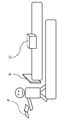
- FIG. 1A is an external view illustrating an example of a user entering the gate system of the present disclosure.
- FIG. 1B is an external view illustrating an example of a user leaving without leaving a passport in the gate system of the present disclosure.
- FIG. 1C is an external view illustrating an example in which a user leaves the passport and leaves the gate system according to the present disclosure.
- FIG. 2 is a functional block diagram illustrating a configuration of the gate system control device of the present disclosure.
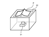
- FIG. 3 is an external view illustrating an example of a reading device in the gate system of the present disclosure.
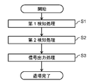
- FIG. 4 is a flowchart illustrating the operation of the gate system control device of the present disclosure.
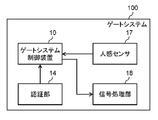
- FIG. 5 is a diagram illustrating an example of the configuration of the gate system according to the embodiment.
- FIG. 1A is an external view illustrating an example of a user entering the gate system of the present disclosure.
- FIG. 1B is an external view illustrating an example of a user leaving without leaving a passport in the gate system of the present
- FIG. 6 is a diagram showing an example of a detailed configuration of the gate system shown in FIG.
- FIG. 7 is a diagram illustrating an example of a detailed configuration of the first detection unit illustrated in FIG. 6.
- FIG. 8 is a diagram illustrating an example of a hardware configuration of the gate system control device according to the embodiment.
- FIG. 9 is a flowchart showing the operation of the gate system shown in FIG.
- FIG. 10 is a flowchart illustrating the operation of the gate system according to the first embodiment.
- FIG. 11 is a flowchart illustrating the operation of the gate system according to the second embodiment.
- FIG. 12 is a flowchart illustrating the operation of the gate system according to the third embodiment.
- FIG. 13 is a flowchart illustrating the operation of the gate system according to the fourth embodiment.
- FIG. 9 is a flowchart showing the operation of the gate system shown in FIG.
- FIG. 10 is a flowchart illustrating the operation of the gate system according to the first embodiment.
- FIG. 11
- FIG. 14 is a flowchart illustrating the operation of the gate system according to the fifth embodiment.
- FIG. 15 is a flowchart illustrating an operation when the first detection unit according to the sixth embodiment detects how to place a passport.
- FIG. 16A is an explanatory diagram illustrating an example of a horizontal detection method for a passport according to the sixth embodiment.
- FIG. 16B is an explanatory diagram of an example of a horizontal detection method for a passport according to the sixth embodiment.
- FIG. 17A is an explanatory diagram of an example of a method for detecting the vertical placement of a passport according to the sixth embodiment.
- FIG. 17B is an explanatory diagram of an example of a method for detecting the vertical placement of a passport according to the sixth embodiment.
- FIG. 16A is an explanatory diagram of an example of a method for detecting the vertical placement of a passport according to the sixth embodiment.
- FIG. 17B is an explanatory diagram of an example of a method for detecting the vertical placement of a passport
- FIG. 18 is an explanatory diagram of another example of the horizontal detection method of the passport according to the sixth embodiment.
- FIG. 19 is an explanatory diagram of an example of a method for detecting an oblique passport placement according to the sixth embodiment.
- FIG. 20A is an explanatory diagram of another example of a passport placement detection method according to the sixth embodiment.
- FIG. 20B is an explanatory diagram of another example of a method for detecting how to place a passport in the sixth embodiment.
- FIG. 20C is an explanatory diagram of another example of a method for detecting how to place a passport in the sixth embodiment.
- FIG. 21 is a flowchart illustrating an operation when the first detection unit according to the sixth embodiment detects how to place a passport.
- FIG. 21 is a flowchart illustrating an operation when the first detection unit according to the sixth embodiment detects how to place a passport.
- FIG. 22 is a flowchart illustrating the operation of the first detection unit according to the seventh embodiment.
- FIG. 23 is an explanatory diagram of an example of the acquisition timing of the background image in the eighth embodiment.
- FIG. 24 is an explanatory diagram of an example of the acquisition timing of the background image in the eighth embodiment.
- FIG. 25 is an explanatory diagram of an example of the acquisition timing of the background image in the eighth embodiment.
- FIG. 26 is a flowchart illustrating an example of the operation of the first detection unit according to the eighth embodiment.
- FIG. 27 is a flowchart illustrating an operation when the first detection unit according to the ninth embodiment adjusts the setting of the image sensor.
- FIG. 28 is an explanatory diagram of an example of an image obtained by imaging the placement area in the ninth embodiment.
- FIG. 29 is an explanatory diagram of an example of an image obtained by imaging the placement area in the ninth embodiment.
- FIG. 30A is an explanatory diagram of a range captured by the image sensor according to the ninth embodiment.
- FIG. 30B is an explanatory diagram of a range captured by the image sensor according to the ninth embodiment.
- FIG. 31 is a flowchart illustrating the operation performed by the reading unit according to the tenth embodiment.
- FIG. 32 is an explanatory diagram of unique features of the passport according to the tenth embodiment.
- FIG. 33 is an explanatory diagram of unique features of the passport according to the tenth embodiment.
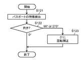
- FIG. 34 is a flowchart illustrating the operation performed by the reading unit according to the eleventh embodiment.
- FIG. 35 is a flowchart illustrating operations performed by the first detection unit according to the twelfth embodiment.
- FIG. 36 is a flowchart illustrating an operation performed by the gate system control apparatus according to the modification.
- drawings are schematic diagrams in which emphasis, omission, and ratio adjustment are appropriately performed to show the present disclosure, and may differ from actual shapes, positional relationships, and ratios.
- the gate system has an exit gate for a person holding a passport to exit (exit), and can open and close the exit gate. This gate system will be described.
- FIG. 1A, 1B, and 1C are external views illustrating an example of the gate system of the present disclosure.
- FIG. 1A is an external view showing an example of a user entering the gate system of the present disclosure.
- the person who possesses the passport P enters the gate system and authenticates the passport P by placing the passport P in the placement area 22 of the gate system.
- FIG. 1B is an external view showing an example of a user leaving without leaving a passport in the gate system of the present disclosure.
- the exit gate G opens. A person who has the passport P can get out by picking up the passport P and passing through the exit gate G.
- FIG. 1C is an external view showing an example in which the user leaves the passport in the gate system of the present disclosure and exits.
- the exit gate G opens as in FIG. 1B.
- the gate system issues a notice of misplacement.
- the gate system of the present disclosure issues a notification of misplacement by making a sound, prevents the exit gate G from being left by closing the exit gate G, etc. A warning notice is given.
- FIG. 2 is a functional block diagram illustrating a configuration of the gate system control device 1 of the present disclosure.
- the gate system control device 1 shown in FIG. 2 includes a first detection unit 2, a second detection unit 3, and a controller 4.
- 1st detection part 2 detects that the passport which the person who entered the gate system has is mounted in the mounting area. More specifically, the 1st detection part 2 detects that the passport of the said person is mounted in the mounting area based on the image of the mounting area where the passport is mounted.
- the image of the placement area is, for example, an image captured by an image sensor.
- the second detection unit 3 detects that the person is moving. More specifically, the second detection unit 3 detects the exit timing at which the person exits the exit gate.
- the exit timing is a timing at which the person is moving toward the exit gate and the person exits the exit gate.
- Controller 4 controls the gate system.
- the controller 4 outputs a signal for causing the gate system to perform a process of noticing that the passport remains placed at the exit timing. That is, the controller 4 has detected that the 1st detection part 2 has mounted the passport in the mounting area, and the 2nd detection part 3 has detected that the person is moving.
- the gate system is caused to execute processing for notifying a person.
- FIG. 3 is an external view showing an example of a reading device in the gate system of the present disclosure.
- the reading device has a placement area 22.
- the placement area 22 is made of a transparent glass surface, and the passport P is placed thereon. Therefore, the image sensor 31 may image the glass surface, that is, the placement area 22 from below the glass surface.
- the gate system control device 1 can cause the gate system to close, for example, half or all of the exit gate, or notify the person of misplacement. Therefore, misplacement of the passport of the person can be prevented.
- FIG. 4 is a flowchart showing the operation of the gate system control device 1 shown in FIG.
- the gate system control device 1 performs a first detection process (S1). Specifically, the first detection unit 2 of the gate system control device 1 detects that a passport possessed by a person who has entered the gate system is placed in the placement area.
- the gate system control device 1 performs a second detection process (S2). Specifically, the second detection unit 3 of the gate system control device 1 detects the exit timing at which the person exits the exit gate.
- the gate system control device 1 performs signal output processing (S3). Specifically, the controller 4 of the gate system control device 1 outputs a signal for causing the gate system to perform a process of noticing that the passport is still placed at the exit timing.
- FIG. 5 is a diagram illustrating an example of a configuration of the gate system 100 according to the present embodiment.
- FIG. 6 is a diagram showing an example of a detailed configuration of the gate system 100 shown in FIG.
- the gate system 100 includes a gate system control device 10, an authentication unit 14, a human sensor 17, and a signal processing unit 18.
- the gate system control device 10 includes a first detection unit 11, a second detection unit 12, and a controller 13.
- the first detection unit 11 is a specific example of the first detection unit 2 and detects that a passport possessed by a person who has entered the gate system is placed in the placement area.
- the first detection unit 11 detects that the passport is placed in the placement area based on the image of the placement area where the passport imaged by the image sensor is placed.
- the placement area is a rectangular area.
- the length in the longitudinal direction of the placement region is larger than the length in the longitudinal direction of the passport in the spread state. Further, the length of the placement region in the short direction is larger than the short direction of the passport in the spread state and smaller than the length of the passport in the spread direction.
- FIG. 7 is a diagram illustrating an example of a detailed configuration of the first detection unit 11 illustrated in FIG. 6.
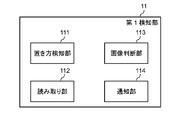
- the first detection unit 11 includes a placement detection unit 111, a reading unit 112, an image determination unit 113, and a notification unit 114.
- the placement detection unit 111 detects the placement of the passport in the placement area based on the image of the placement area captured by the image sensor. Passports can be placed horizontally, vertically or diagonally. That is, the placement detection unit 111 detects whether the passport is placed horizontally based on the image of the placement area.
- how to place the passport in the placement area when the longitudinal direction of the passport in the spread state is placed along the longitudinal direction of the placement area is referred to as horizontal placement.
- the method of placing the passport in the placement area when the short direction of the passport in the spread state is placed along the longitudinal direction of the placement area is referred to as vertical placement.
- the method of placing the passport in the placement area in a state other than horizontal placement and vertical placement is referred to as oblique placement.
- the first detection unit 11 detects that the placement detection unit 111 detects that the placement of the passport in the placement region is horizontal in the placement region image captured by the image sensor. Detects that a passport is placed. That is, when the passport is placed on the placement area so that the longitudinal direction of the passport in the spread state is along the longitudinal direction of the placement area, the placement detection unit 111 detects that the passport is horizontally placed. .
- the reading unit 112 reads information indicated by the passport based on the passport image captured by the image sensor.
- the reading unit 112 reads information shown in the passport based on the passport image captured by the image sensor after the placement detecting unit 111 detects that the passport is placed sideways. That is, the reading unit 112 reads the information shown in the passport after the placement detecting unit 111 detects that the passport is placed.
- the reading unit 112 may determine whether the direction of the passport is reversed based on the characteristic of the passport in the passport image captured by the image sensor. When the passport is reversed, the reading unit 112 may rotate the passport image by 180 ° and read information indicated by the passport.
- the feature here may be MRZ (Machine-Readable-Zone), the position of a photo or hologram, or the orientation of a page number, photo or text.
- the information shown in the passport is, for example, a face photograph attached to the passport, a name written in the MRZ, a passport number, date of birth, nationality, and the like.
- the reading unit 112 may read the information indicated in the passport based on the image rotated by 90 ° even if the orientation of the passport is vertical based on the unique characteristics of the passport reflected in the image. Further, the reading unit 112 may determine whether or not the person is a target person who can use the gate system 100 based on the MRZ information of the passport.
- the image determination unit 113 determines the status of the installation location of the image sensor. For example, the image determination unit 113 may determine the environmental illuminance that is the illuminance around the installation location of the image sensor, and determine whether or not the average brightness of the surrounding area of the placement area is greater than or equal to a threshold value. May be. Accordingly, the first detection unit 11 can adjust the exposure of the image sensor according to the situation determined by the image determination unit 113. Note that a person in charge of maintaining the gate system control device 10 may manually adjust the exposure of the image sensor.
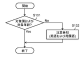
- the notifying unit 114 notifies the person that the passport is not placed in the placement area when the placement detecting unit 111 detects that the passport is placed in a place other than landscape. Further, based on the information read by the reading unit 112, the notification unit 114 may notify the person that the person is not a target person when the person is not a target person who can use the gate system 100.
- the notification unit 114 may notify a person by voice using a speaker or the like. Further, for example, when the person is a person in another country who is not a target person who can use the gate system 100, the notification unit 114 may notify the person in the native language of the person.
- the first detection unit 11 detects that the passport is placed based on the image of the placement area where the passport imaged by the image sensor is placed.
- the 1st detection part 11 may detect that the passport is mounted by light, such as infrared rays, and a switch.
- the gate system irradiates infrared rays in a direction intersecting with the placement area and receives the infrared rays.
- the first detection unit 11 may detect that the passport is placed in the placement area when the passport placed in the placement area blocks a part of infrared rays.
- the 1st detection part 11 may be provided with the switch which has a protrusion part in a part of mounting area.
- the first detector 11 may detect that the passport is placed. Moreover, the 1st detection part 11 may detect that the passport was set
- the second detection unit 12 is a specific example of the second detection unit 3 and detects the exit timing at which the person exits the exit gate.
- the 2nd detection part 12 acquires the signal which the human sensor 17 installed, for example in the vicinity of a leaving gate detects via a network. Thereby, the 2nd detection part 12 detects the exit timing in which the said person exits from an exit gate.
- the network may be a wired network or a wireless network.
- the controller 13 is a specific example of the controller 4 and outputs a signal for causing the gate system 100 to perform a process of noticing misplacement.
- the controller 13 outputs a signal for causing the signal processing unit 18 to perform a process for notifying misplacement, and causes the signal processing unit 18 to perform a process for notifying misplacement.
- the controller 13 completes the authentication of the person's passport and starts moving so that the person passes through the exit gate, and the exit timing when the person exits the exit gate.
- the signal is output to the signal processing unit 18.
- FIG. 8 is a diagram illustrating an example of a hardware configuration of the gate system control apparatus 10 according to the embodiment.
- the gate system control device 10 is realized by the computer 1000.
- the computer 1000 includes a CPU 1001, a ROM 1003, a RAM 1002, a communication IF 1004, a sensor 1006, an internal light source 1007, and a speaker 1008.
- the CPU 1001, ROM 1003, RAM 1002, communication IF 1004, sensor 1006, internal light source 1007, and speaker 1008 are connected by a communication bus 1005.
- the CPU 1001 is a central processing unit (central processing unit), and executes a control program or the like stored in the ROM 1003. Thereby, the CPU 1001 performs various processes by controlling, for example, the communication IF 1004, the sensor 1006, the internal light source 1007, the speaker 1008, and the like.
- ROM 1003 is a Read Only Memory, and stores programs and data in advance.
- the RAM 1002 is a Random Access Memory, and is used for storing data and the like when executing a program.
- the RAM 1002 may be a storage such as a hard disk drive or a solid state drive.
- the communication IF 1004 is an interface for communicating with the authentication unit 14, the human sensor 17, and the signal processing unit 18 in a wireless or wired manner, for example, a communication circuit.
- Sensor 1006 is a sensor such as an image sensor and is controlled by CPU 1001. In the case where the sensor 1006 is an image sensor, not only imaging with visible light but imaging with IR (infrared) may be performed.
- the internal light source 1007 is a light source used by the sensor 1006 and includes, for example, an LED or a lamp.
- the internal light source 1007 is used by the sensor 1006 to read information indicated in the passport.
- the internal light source 1007 is controlled by the CPU 1001 to be turned on or off.
- the speaker 1008 is used for notifying a person that the passport is placed in a placement area other than landscape when the placement is other than landscape.
- the speaker 1008 is controlled by the CPU 1001.
- the authentication unit 14 authenticates the passport owner.
- the authentication unit 14 includes an IC reader unit 15 and a personal authentication unit 16 as shown in FIG.
- the IC reader unit 15 reads information stored in the IC chip of the passport.
- the IC reader unit 15 has a known configuration for reading information from the IC chip of the passport without contact.
- the IC reader unit 15 reads information stored in the IC chip of the passport placed in the placement area.
- the personal authentication unit 16 performs personal authentication as to whether or not the person indicated in the information read by the IC reader unit 15 matches the person who is the holder of the passport. For example, when the gate system 100 further includes a camera, the personal authentication unit 16 includes the face of the person who is the owner of the passport imaged by the camera and the person included in the information read by the IC reader unit 15. It may be verified that the person is the same person. When the gate system 100 can acquire the fingerprint, vein, retina, etc. of the person holding the passport, the personal authentication unit 16 reads the fingerprint, vein, retina, etc. and the information read by the IC reader unit 15. Biometric authentication that collates fingerprints, veins, retinas, and the like included in the image may be performed.
- the human sensor 17 is a sensor that detects a person approaching the exit gate of the gate system 100, and transmits a signal indicating the detection result to the gate system control device 10.
- the human sensor 17 may be configured with a camera.
- An example of the human sensor 17 is an infrared sensor. That is, the second detection unit 12 may detect that a person is moving based on the output of the infrared sensor.
- the signal processing unit 18 performs processing for notifying a person of misplacement according to a signal output from the gate system control device 10.
- the signal processing unit 18 includes an exit gate control unit 19 and a voice notification unit 21 as shown in FIG.
- the exit gate control unit 19 controls the opening and closing of the exit gate according to a signal output from the gate system control device 10.
- the voice notification unit 21 makes a voice notification informing the person of misplacement according to the signal output from the gate system control device 10.
- FIG. 9 is a flowchart showing the operation of the gate system 100 shown in FIG. Based on the information held in the passport of the person who has passed through the entrance gate, the gate system 100 checks whether the person is the person who owns the passport. Then, the gate system 100 opens the exit gate when the identity can be authenticated.
- the person enters the area in the gate system 100 from the entrance gate (S10).
- the person places the passport in the placement area where the passport is placed.
- the gate system 100 performs a placement detection process that detects the placement of the passport in the placement area (S11).
- the gate system 100 detects how the passport is placed in the placement area, and detects that the passport is placed when the passport is placed horizontally.
- the gate system 100 performs a reading process of reading information indicated in the passport (S12).
- the information shown in the passport is, for example, a photograph.
- the information shown in the read passport is sent to a person in charge such as an examiner who keeps in the vicinity of the exit gate, and is used to confirm the person who passes the exit gate.
- the gate system 100 performs an authentication process for confirming whether or not the person has the passport (S13).
- the gate system 100 When the authentication process (S13) ends and the person starts moving to pass the exit gate, the gate system 100 performs exit processing (S14). That is, when detecting misplacement, the gate system 100 performs processing for notifying the person of misplacement, and when not detecting misplacement, performs processing for allowing the person to pass through the exit gate as it is.
- the gate system 100 can prevent the passport of the person from being left behind.
- Example 1 In the present embodiment, a case where the process for recognizing misplacement is a process for closing the exit gate will be described.
- FIG. 10 is a flowchart showing the operation of the gate system 100 according to the first embodiment.
- the flowchart shown in FIG. 10 corresponds to an example of details of the exit processing (S14) shown in FIG.
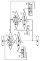
- the exit gate control unit 19 first performs a process of opening the exit gate (S21).
- the gate system 100 confirms whether a passport is placed in the placement area (S22). More specifically, the first detection unit 11 of the gate system control device 10 detects whether or not the passport is placed in the placement area.
- the gate system 100 proceeds to the process of S23. If the exit gate has not yet been opened (No in S23), the exit gate control unit 19 performs a process of opening the exit gate. In S23, if the exit gate is already open (Yes in S23), the process is terminated.
- the gate system 100 determines whether the person is heading to the exit gate (S25). More specifically, the second detection unit 12 detects, based on a signal detected by the human sensor 17, whether the person is going to the exit gate and the exit timing is when the person exits the exit gate. .
- the exit gate control unit 19 performs a process of closing the exit gate (S26). More specifically, the controller 13 exits as a process for recognizing misplacement when the first detection unit 11 detects that the passport is placed at the exit timing detected by the second detection unit 12. Outputs a signal to close the gate. Then, the exit gate control unit 19 performs control to close the exit gate according to the signal output from the controller 13.
- the gate system 100 may perform a misplacement notice to notify the user of the misplacement (S27). More specifically, the controller 13 may further output a signal for generating an alarm notifying that the passport is still mounted, and cause the voice notification unit 21 to generate an alarm.
- the exit gate when a person tries to leave the exit gate while leaving his / her passport, the exit gate may be closed to notice the misplacement. That is, the controller 13 causes the gate system to execute a process of closing the exit gate as a process of notifying the person.
- the controller 13 outputs a signal for closing all the exit gates, and controls the exit gate control unit 19 to close all the exit gates.
- the control of the controller 13 is not limited to this.
- the controller 13 may output a signal for closing half or more than half, and may control the exit gate control unit 19 to close the exit gate half or more than half. In this case, it is possible to alert a person who has left the passport misplaced while preventing the person from leaving the passport from being caught in the exit gate.
- Example 2 In the present embodiment, a case will be described in which the process for recognizing misplacement is a process for voice notification with a personal name.
- FIG. 11 is a flowchart showing the operation of the gate system 100 according to the second embodiment.
- the flowchart shown in FIG. 11 corresponds to an example of the details of the exit processing (S14) shown in FIG.
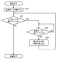
- the exit gate control unit 19 performs a process of opening the exit gate (S31).
- the gate system 100 confirms whether a passport is placed in the placement area (S32). More specifically, the first detection unit 11 of the gate system control device 10 detects whether or not the passport is placed in the placement area.
- the gate system 100 determines whether a person is heading to the exit gate (S33). More specifically, the second detection unit 12 detects, based on a signal detected by the human sensor 17, whether the person is going to the exit gate and the exit timing is when the person exits the exit gate. .
- the gate system 100 performs a process of notifying the voice notification unit 21 by voice so as to notice the misplacement (S34). More specifically, the controller 13 may output a signal that includes the personal name of the person and that indicates that the passport is still placed and causes the voice notification unit 21 to emit the sound. .
- the personal name of the person is acquired by the reading process (S12) or the authentication process (S13) shown in FIG.
- the controller 13 makes the first detector 11 notice the misplacement when the first detector 11 detects that the passport is placed at the exit timing detected by the second detector 12.
- a signal for outputting a sound for notifying that the passport is still placed including the name of the person included in the passport is output. That is, the reading unit 112 may acquire a person's name from information indicated in the passport.
- the controller 13 may cause the gate system to execute a process of emitting a sound including the name of the person as a process of notifying the person.
- Example 3 In the present embodiment, a case where the process for recognizing misplacement is a process that does not open the exit gate will be described. In the following description, it is assumed that when a person enters from the entrance gate, the exit gate remains closed.
- FIG. 12 is a flowchart showing the operation of the gate system 100 according to the third embodiment.
- the flowchart shown in FIG. 12 corresponds to an example of details of the exit processing (S14) shown in FIG.
- the gate system 100 confirms whether a passport is placed in the placement area (S41). More specifically, the first detection unit 11 of the gate system control device 10 detects whether or not the passport is placed in the placement area.
- the gate system 100 opens the exit gate (S42). More specifically, when the first detection unit 11 detects a state where no passport is placed in the placement area, the controller 13 outputs a signal for opening the exit gate to the signal processing unit 18. When the exit gate control unit 19 acquires this signal, the exit gate control unit 19 performs a process of opening the exit gate.
- the process returns to S41. More specifically, when a passport is placed in the placement area, the gate system 100 may keep the exit gate closed by performing no processing. Further, when a passport is placed in the placement area, the controller 13 detects that the first detection unit 11 is placed at the exit timing detected by the second detection unit 12. As a process for recognizing misplacement, a signal for keeping the exit gate closed may be output. Thereby, the exit gate control part 19 can perform the process which maintains an exit gate in the closed state.
- the exit gate may be prevented from opening so that the person may notice the misplacement.
- the gate system includes an entrance gate for a person with a passport to enter.
- the signal processing unit 18 includes an entrance gate control unit (not shown) that controls the opening and closing of the entrance gate in accordance with a signal output from the gate system control device 10.
- the process for noticing misplacement is a process for preventing the next person from entering without opening the entrance gate.
- the said entrance gate demonstrates the state which is closed.
- FIG. 13 is a flowchart showing the operation of the gate system 100 according to the fourth embodiment.
- the flowchart shown in FIG. 13 corresponds to an example of the details of the exit processing (S14) shown in FIG.
- the gate system 100 checks whether a passport is placed in the placement area (S51). More specifically, the first detection unit 11 of the gate system control device 10 detects whether or not the passport is placed in the placement area.
- the gate system 100 opens the entrance gate (S52). More specifically, when the first detection unit 11 detects a state where no passport is placed in the placement area, the controller 13 outputs a signal for opening the entrance gate to the signal processing unit 18. When the entrance gate control unit acquires this signal, it performs a process of opening the entrance gate.
- the gate system 100 keeps the entrance gate closed (S53). Then, the process returns to S51. More specifically, when a passport is placed in the placement area, the gate system 100 may perform no processing and keep the entrance gate closed. Further, when a passport is placed in the placement area, the controller 13 detects that the first detection unit 11 is placed at the exit timing detected by the second detection unit 12. As a process of noticing misplacement, a signal for keeping the entrance gate closed may be output.
- the entrance gate is kept closed so that the next person (person) cannot enter. In this way, misplacement may be noticed. Thereby, it is possible to prevent the next person from removing the passport. In addition, it is possible to prevent a person from entering and leaving the country with a passport left behind.
- Example 5 In the present embodiment, a case will be described in which in the gate system 100, it is possible for a person to desire an examiner to push an entry / exit stamp into the passport after passing through the exit gate.
- the gate system control device 10 further includes a stamp confirmation unit (not shown).
- the stamp confirmation unit confirms with the person whether or not he / she wishes to imprint an immigration stamp on the passport after the person is authenticated using the passport.
- the controller 13 further outputs a signal indicating that the person should perform the immigration stamp after leaving the exit gate when the stamp confirmation unit confirms that the immigration stamp is desired. .
- the controller 13 outputs this signal to a terminal used by the examiner who keeps the signal near the exit gate of the gate system 100.
- FIG. 14 is a flowchart showing the operation of the gate system 100 according to the fifth embodiment.
- the flowchart shown in FIG. 14 corresponds to an example of processing performed after the authentication processing (S13) shown in FIG.
- the flowchart shown in FIG. 14 may be performed, for example, between the authentication process (S13) and the exit process (S14), or may be performed after the exit process (S14).
- the gate system 100 confirms with a person whether or not a stamp is desired (S54).
- “to request a stamp” means that the examiner will ask the passport to stamp a dated immigration stamp.
- the controller 13 of the gate system control apparatus 10 may output a signal for confirming whether or not the stamp is desired after the person authentication process using the passport by the authentication unit 14.
- the display at a position where the person can be confirmed displays a screen for confirming with the person whether or not the stamp is desired. This display may be included in the gate system control apparatus 10 or in the vicinity of the placement area.
- the immigration stamp is stamped after the person leaves the exit gate (S55). More specifically, the gate system 100 is used by an examiner who keeps a signal indicating that the person should stamp an entry / exit stamp after leaving the exit gate when the person wants to stamp. Output to the terminal. As a result, after the person leaves the exit gate, the examiner stamps the immigration stamp.
- the person can perform an action that can be performed by imprinting the immigration stamp on the passport.
- the actions that can be performed by imprinting an immigration stamp on the passport include shopping using tax exemption.
- the gate system 100 outputs a signal indicating that an immigration stamp should be stamped to a terminal used by an examiner who keeps near the exit gate.
- the gate system 100 may have a mechanism for imprinting an immigration stamp.
- the gate system 100 may stamp the entry / exit stamp by automatically searching for an empty space in the passport or by designating a place where the person wants to stamp.
- Example 6 In the present embodiment, a description will be given of a process in which the first detection unit 11 detects how to place a passport and notifies the fact when it is not in landscape orientation.
- similar elements are denoted by the same reference numerals, and detailed description thereof is omitted.
- FIG. 15 is a flowchart illustrating an operation when the first detection unit 11 according to the sixth embodiment detects how to place a passport.
- the flowchart shown in FIG. 15 corresponds to an example of details of the placement detection process (S11) shown in FIG.
- the first detection unit 11 detects whether or not the passport is placed in the placement area in the horizontal orientation (S61). More specifically, the placement detection unit 111 detects whether or not the passport is placed in the placement area based on the image of the placement area captured by the image sensor.
- the placement detection unit 111 uses a post-processing image that is an image obtained by performing binarization processing by the background subtraction method or the image level on the image of the placement area imaged by the image sensor. Detects such as. Details of this detection method will be described later.
- the first detection unit 11 detects whether the passport is placed vertically in the placement area. (S62). More specifically, the placement detection unit 111 detects whether the passport is placed vertically in the placement area based on the image of the placement area captured by the image sensor.
- the first detection unit 11 notifies that the passport is placed vertically (S63). Then, the process returns to S61. More specifically, when the placement detection unit 111 detects that the passport is placed vertically, the notification unit 114 notifies the person that the passport is placed vertically. If it is detected in S62 that the passport is not placed vertically (No in S62), the process returns to S61.
- the notification unit 114 notifies the person that the passport is placed vertically, the present invention is not limited to this. You may notify that it is urged to place the passport horizontally.
- the first detection unit 11 when the passport is placed vertically in the placement area, the first detection unit 11 notifies that the placement is wrong or should be placed horizontally. To do. That is, when the passport is not in landscape orientation, the controller 13 causes the gate system to execute processing for notifying the person that the passport is not in landscape orientation. As a result, the automatic examination of the passport can be started, so that the examination time can be shortened.
- the placement detection unit 111 fills the placement area in the post-processing image, which is an image after performing binarization processing by the background difference method or the image level on the image of the placement area captured by the image sensor. A shape pattern formed by white pixels is detected. Thereby, the placement detection unit 111 may detect the placement of the passport in the placement area.
- the background subtraction method is a method of calculating a difference (absolute value) from the current input image using the background image and extracting a target object appearing in the input image by performing appropriate threshold processing.
- the image of the placement area in which no passport is placed corresponds to the background image
- the image of the placement area in which the passport is placed corresponds to the input image.
- the placement detection unit 111 detects that the placement of the passport in the placement area is horizontal or other than horizontal by detecting the ratio of white pixels filling the placement area in the processed image. May be. Hereinafter, this will be described with reference to FIGS. 16A to 17B.
- FIG. 16A and FIG. 16B are explanatory diagrams of an example of a horizontal detection method of a passport in the sixth embodiment.
- FIG. 16A shows a post-processing image that is an image after performing binarization processing by the background subtraction method or the image level on the image of the placement area imaged by the image sensor.
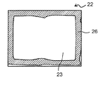
- a placement area 22 is shown, and an area 23 (that is, a white pixel area) is shown.
- the area 23 corresponds to the area of the passport when the passport in the spread state is placed in the placement area 22.
- the placement detection unit 111 moves the frame 23a shown in FIG. 16B in the placement area 22 of the post-processing image shown in FIG. 16A. Then, the placement detection unit 111 searches for a position where the frame 23 a overlaps the area 23 in the placement area 22. At the position where the frame 23a overlaps the area 23 in the placement area 22, if the filling ratio (the ratio of white pixels) of the area 23 (ie, white pixels) in the frame 23a is equal to or greater than the threshold value, the passport is placed horizontally in the area 23 It can be detected that it is being performed.
- the filling ratio the ratio of white pixels
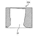
- FIG. 17A and FIG. 17B are explanatory diagrams of an example of a vertical detection method for a passport according to the sixth embodiment.
- FIG. 17A shows a post-processing image that is an image obtained by performing binarization processing by the background difference method or the image level on the image of the placement area imaged by the image sensor.
- the post-processing image shown in FIG. 17A shows a placement area 22a and an area 24 (that is, a white pixel area).
- the area 24 corresponds to the passport area when the passport in the spread state is placed in the placement area 22a.
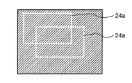
- the placement detection unit 111 moves the frame 24a shown in FIG. 17B in the placement area 22a of the processed image shown in FIG. 17A. Then, the placement detection unit 111 searches for a position where the frame 24a overlaps the area 24 in the placement area 22a. If the filling ratio (the ratio of white pixels) of the area 24 (that is, white pixels) in the frame 24a is equal to or greater than the threshold at the position where the frame 24a overlaps the area 24 in the placement area 22a, the area 24 has a passport vertically It can be detected that it is being performed.
- the placement detection unit 111 detects that the length in the longitudinal direction in the area formed by the white pixels filling the placement area in the processed image is substantially the length in the longitudinal direction of the passport in the spread state. In such a case, it may be detected that the passport is placed horizontally in the placement area. Hereinafter, this will be described with reference to FIGS. 18 and 19.
- FIG. 18 is an explanatory diagram of another example of the horizontal detection method of the passport in the sixth embodiment.
- FIG. 18 shows the placement area 22 and the area 23 (that is, white pixels) in the processed image described with reference to FIG. 16A.
- the placement detection unit 111 is configured so that the continuous pixel length of the white pixels that fill the inside of the placement region 22 in the processed image (the longitudinal length l1 in the region 23 in FIG. 18) If it is the width of the passport at the time, the passport can be detected as being placed vertically.
- the width of the passport when placed horizontally corresponds to the length in the longitudinal direction of the passport in a spread state.
- the placement detection unit 111 may detect that the passport is placed in a placement area other than horizontal placement.
- a case where the passport is placed obliquely will be described with reference to FIG.
- FIG. 19 is an explanatory diagram of an example of a detection method of the diagonal placement of the passport in the sixth embodiment.
- FIG. 19 shows a processed image that is an image after the binarization processing by the background difference method or the image level is performed on the image of the placement area captured by the image sensor.
- the post-processing image shown in FIG. 19 shows a placement area 22c and an area 25, that is, a white pixel area.
- the area 25 corresponds to the passport area when the passport in the spread state is placed in the placement area 22c.
- the placement detection unit 111 includes the horizontal line length l2 and the vertical line length of the placement region 22c of the white pixel (region 25) filling the inside of the placement region 22c in the processed image. Based on the length l3, it can be detected that the passport is placed obliquely. That is, when the lengths l2 and l3 of the horizontal and vertical lines are not substantially constant along the horizontal and vertical directions of the placement region 22c, and increase or decrease, the placement detection unit 111 causes the passport to be placed diagonally. It is because it can be judged that it is done.
- the placement detection unit 111 detects the degree of black pixel filling around the placement area in the processed image, thereby detecting that the passport is placed in the placement area in a landscape orientation or other than landscape orientation. You may do that. This will be described below with reference to FIGS. 20A to 20C.
- 20A to 20C are explanatory diagrams of another example of a method for detecting how to place a passport in the sixth embodiment.
- the post-processing image shown in FIG. 20A shows a placement area 22 and an area 23, and an area 26 that is a black pixel area.
- the post-process image shown in FIG. 20B shows a placement area 22b and an area 24, and an area 27 that is an area of black pixels.
- the placement detection unit 111 determines how the passport is placed in the placement area depending on the degree of black pixel filling in the frame 28 when the frame 28 at the position shown in FIG. 20C is overlaid on FIGS. 20A and 20B. It is possible to detect horizontal or vertical placement. For example, in the placement area 22 of the post-processing image shown in FIG. 20A, the placement detection unit 111 passes the passport if the filling ratio (area of the area 26) of the black pixels overlapping the frame 28 shown in FIG. 20C is smaller than the threshold value. Can be detected. In addition, for example, the placement detection unit 111 determines that the filling ratio (area of the region 27) of the black pixels overlapping the frame 28 illustrated in FIG. 20C is larger than the threshold in the post-processing image placement region 22b illustrated in FIG. 20B. , It can be detected that the passport is placed vertically.
- the placement detection unit 111 uses the background difference method or the image after the binarization processing by the image level to fill a pattern that seems to be horizontally or vertically placed, a degree of filling in the passport (continuous pixel length). ), Or how the vacant area around the passport is detected, it is possible to detect how the passport is placed in the placement area.
- the first detection unit 11 has been described as notifying in S62 of FIG. 15 that the passport is placed vertically after detecting that the passport is placed vertically in the placement area. .
- the person who is trying to place the passport in the placement area may be notified that he / she has noticed himself / herself or after a predetermined time, which is a grace time for trying to place it correctly, to indicate that the passport is placed vertically. That is, the notification unit 114 notifies the person that the passport is placed in the placement area other than the horizontal placement for a predetermined time when the placement detection unit 111 detects that the passport is not placed horizontally. May be.
- this will be described with reference to FIG.
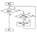
- FIG. 21 is a flowchart illustrating an operation when the first detection unit 11 according to the sixth embodiment detects how to place a passport.
- the flowchart shown in FIG. 21 corresponds to an example of details of the placement detection process (S11) shown in FIG. Elements similar to those in FIG. 15 are denoted by the same reference numerals, and detailed description thereof is omitted.
- the first detection unit 11 continues to place the passport in the placement area for 3 seconds or longer. It is detected whether it is a set (S72). More specifically, based on the image of the placement area captured by the placement sensor 111 by the image sensor, it is determined whether the passport is placed in the placement area continuously for 3 seconds or more. Detect.
- 3 seconds or more is an example of the predetermined time, and the predetermined time is not limited to this.
- the first detection unit 11 When the placement of the passport in the placement area continues vertically for 3 seconds or longer (Yes in S72), the first detection unit 11 notifies that it is vertically placed (S73).
- the placement detection unit 111 may generate a binarized image (processed image) from the placement area image. Then, the placement detection unit 111 may detect whether or not the passport is placed horizontally by using the binarized image.
- the placement detection unit 111 uses the binarized image in a first area (area 23) corresponding to the passport or an area other than the area corresponding to the passport in the placement area. A certain second area (area 26) may be detected. The placement detection unit 111 may detect whether or not the passport is placed horizontally based on the first area or the second area.
- the placement detection unit 111 may detect whether or not the passport is placed horizontally based on the ratio between the area of the predetermined region (frame 23a) and the area of the first region (region 23). Alternatively, the placement detection unit 111 may detect whether or not the passport is placed horizontally based on the ratio between the area of the predetermined region (frame 28) and the area of the second region (region 26).
- Example 7 a case will be described in which the first detection unit 11 detects how the passport is placed in the placement area by the image sensor without turning on the internal light source.
- the placement area is made of a transparent glass surface, and the passport is placed on the glass surface.
- the image sensor will be described on the assumption that the glass surface (that is, the placement area) is imaged from below the glass surface, and the internal light source is installed below the glass surface.
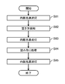
- FIG. 22 is a flowchart illustrating the operation of the first detection unit 11 according to the seventh embodiment.
- FIG. 22 corresponds to an example of processing up to the authentication processing shown in FIG.
- the first detection unit 11 turns off the internal light source (S81).
- the first detection unit 11 detects how to place the passport in the placement area with the internal light source turned off (S82).
- the process of S82 corresponds to the placement detection process shown in FIG. Since the details are as described above, description thereof is omitted here.
- the first detection unit 11 turns on the internal light source (S83).
- the first detection unit 11 reads information indicated in the passport based on the passport image captured by the image sensor (S84). Note that the processing in S84 corresponds to the reading processing shown in FIG.
- the first detection unit 11 turns off the internal light source (S85).
- the internal light source is not illuminated until the person places the passport on the placement area and the glass surface of the placement area is covered. Accordingly, it is possible to prevent the person from feeling dazzled when placing the passport on the placement area.
- Example 8 background image acquisition timing will be described.
- the background image is used when processing by the background difference method is performed on the image of the placement area.
- the image of the placement area where the passport is not placed corresponds to the background image
- the image of the placement area where the passport is placed corresponds to the input image.
- similar elements are denoted by the same reference numerals, and detailed description thereof is omitted.
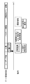
- FIG. 23 is an explanatory diagram of an example of the acquisition timing of the background image in the eighth embodiment.
- the gate region state means the state of the region in the gate system 100.
- the operation means the operation of the first detection unit 11.
- the first detection unit 11 captures (acquires) a background image according to an entrance trigger or an exit trigger when a person exits from the area.
- the entrance trigger is a timing when a person enters an area in the gate system 100 and before a passport is placed in the placement area.
- the entrance trigger is a timing at which the gate system control device 10 outputs a signal for opening the entrance gate to pass the person to the entrance gate control unit.
- the entrance trigger may be a timing at which a human sensor that detects that a person has entered the gate system has detected the person.
- the exit trigger is, for example, the timing at which the gate system control device 10 outputs a signal for opening the exit gate to allow the person to pass to the exit gate control unit 19.
- the first detection unit 11 is in a state where no passport is placed when there is no person in the area between the entrance gate and the exit gate when the placement detection unit 111 performs processing by the background difference method.
- the image of the placement area may be acquired as the background image.
- the placement detection unit 111 uses the image of the placement area in which the passport is not placed as the background image in the background subtraction method. That is, the first detection unit 11 obtains a background image when a person enters or exits, so that when there is no person in the area in the gate system 100, the first detection unit 11 is an image of the placement area in which no passport is placed. A certain background image can be reliably acquired. Thereby, since acquisition of a background image does not fail, the 1st detection part 11 can perform the process by a background difference method stably.
- FIG. 24 is an explanatory diagram of an example of the acquisition timing of the background image in the eighth embodiment.
- the first detection unit 11 captures (acquires) a background image before a person enters the area in the gate system 100 (a state in which no person is present).
- the first detection unit 11 may periodically capture a background image in the absence of a person and update the background image held in a memory (not shown) or the like each time.
- the first detection unit 11 periodically captures a background image in the absence of a person, but updates the background image held in a memory (not shown) or the like only when the background situation changes. May be.
- the ambient illuminance which is the illuminance around the installation location of the image sensor, is changed.
- the 1st detection part 11 can acquire the background image which is an image of the mounting area
- the background image is not limited to the one captured at the acquisition timing as described above.
- the previous background image that has been successfully captured may be used. This will be described with reference to FIGS. 25 and 26.
- FIG. 25 is an explanatory diagram of an example of the acquisition timing of the background image in the eighth embodiment.
- FIG. 26 is a flowchart illustrating an example of the operation of the first detection unit 11 in the eighth embodiment.
- the first detection unit 11 acquires (captures) a background image (hereinafter also referred to as a background at the time of entrance or a background image at this time) according to an entrance trigger.
- the first detection unit 11 determines whether or not the placement detection process based on the acquired background at the time of entry has timed out (S91).
- the time-out means a case where a preset time is exceeded.
- the first detection unit 11 confirms whether the placement detection process has been completed (S92). If the placement detection process has been completed (Yes in S92), as shown in FIG. 25, the entrance background is stored as a successful background image (hereinafter also referred to as the previous background image), and the process ends.
- S92 when the placement detection process has not been completed (No in S92), the time taken for the placement detection process using the background at the time of entry (time of background process at the time of entry) is added (S93). Then, the process returns to S91.
- the admission background process time added in S93 is used in the process of S91.
- the background processing time at the time of entry is, for example, about 3 to 5 seconds.
- the first detection unit 11 proceeds to the placement detection process based on the previous background image stored in the previous process. Then, the first detection unit 11 determines whether or not the placement detection process using the background image has timed out last time (S94).
- S94 if the placement detection process using the previous background image has not timed out (No in S94), it is confirmed whether the placement detection process using the previous background image has been completed (S95). If completed (Yes in S95), as shown in FIG. 25, the previous background image is saved as a successful background image, and the process ends. If not completed (No in S95), the time (processing time for the previous background image) used for the placement detection process using the previous background image is added (S96). Then, the process returns to S94.
- the first detection unit 11 notifies (notifies) the alarm to the person in charge of the gate system 100 (S97).
- the first detection unit 11 uses the previous background image that has succeeded in the previous placement detection process when the placement detection process using the background image has failed this time.
- the 1st detection part 11 can perform the process by a background difference method stably.
- Example 9 In the present embodiment, an example will be described in which the image determination unit 113 of the first detection unit 11 determines the status of the installation location of the image sensor.
- similar elements are denoted by the same reference numerals, and detailed description thereof is omitted.
- the placement area is made of a transparent glass surface, and the passport is placed on the glass surface.
- the image sensor will be described on the assumption that the glass surface, that is, the placement region is imaged from below the glass surface, and the placement region has no cover for avoiding disturbance light.
- FIG. 27 is a flowchart illustrating an operation when the first detection unit 11 according to the ninth embodiment adjusts the setting of the image sensor.
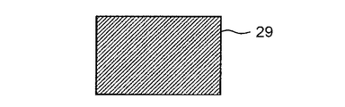
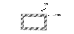
- FIG. 28 and FIG. 29 are explanatory diagrams of an example of an image obtained by capturing the placement area in the ninth embodiment.
- FIG. 28 shows an image 29 obtained by imaging the placement area that is the entire surface of the glass surface.
- FIG. 29 shows a peripheral area 29a corresponding to the peripheral area of the placement area in the image 29 obtained by imaging the placement area, which is the entire surface of the glass surface.
- the surrounding area 29a corresponds to an area in contact with the placement area where the passport is a glass surface when the passport is placed.
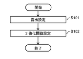
- the first detection unit 11 sets the exposure of the image sensor when the image sensor is installed, at startup, or when the ambient illuminance changes (S101).
- the 1st detection part 11 sets the binarization threshold value for detecting a passport in the image which imaged the mounting area with the image sensor (S102).
- the image determination unit 113 determines the status of the installation location of the image sensor.
- the first detection unit 11 sets the exposure of the image sensor according to the situation determined by the image determination unit 113.
- the above situation may be an ambient illuminance that is the illuminance around the installation location of the image sensor, or a dark portion or a bright portion of an image obtained by imaging the placement area.
- the ratio of the maximum luminance to the minimum luminance among the luminances of all the pixels constituting the image 29 as shown in FIG. 28 may be used.
- the situation may be an average or variance of brightness of all pixels constituting the image 29 shown in FIG. 28, or a standard deviation.
- the controller 13 may adjust the exposure of the image sensor based on the background image. Specifically, the controller 13 may adjust the exposure of the image sensor based on the ratio between the maximum luminance and the minimum luminance among the luminances of the pixels included in the background image.
- the image determination unit 113 determines the change amount (change rate) of the average luminance of the image 29 of the placement area imaged by the image sensor. May be. In this case, the 1st detection part 11 should just set exposure when the said variation
- the image determination unit 113 determines the above situation using all the pixels constituting the image 29 shown in FIG. 28, the present invention is not limited to this. The image determination unit 113 may determine the situation as described above using the pixels constituting the surrounding area 29a shown in FIG.
- FIGS. 30A and 30B are explanatory diagrams of a range captured by the image sensor according to the ninth embodiment.
- 30A and 30B show a placement area 29b and an outer area 30 of the placement area 29b in the ninth embodiment.
- FIG. 30B corresponds to a view when FIG. 30A is viewed from the side when cut along the line AA ′.
- FIG. 30B shows the image sensor 31.
- the first detection unit 11 causes the image sensor 31 to image a range including the placement area 29b and the outer area 30 thereof. And the 1st detection part 11 sets a binarization threshold value from the brightness
- the outer region 30 is not easily affected by light from the outside, the luminance of the outer region 30 is close to the luminance indicated by the passport image placed in the placement region 29b. Therefore, the outer region 30 is used.
- the proportion of pixels with luminance lower than the threshold may exceed a predetermined value of about 30 to 50%.
- the first detection unit 11 may detect that a passport is placed in an image without a passport. Therefore, the first detection unit 11 may return to S101 and redo the exposure setting of the image sensor 31, or may notify that the exposure setting of the image sensor 31 is inappropriate.
- the first detection unit 11 places the passport in the placement area based on the luminance average of the pixels included in the outer area included in the image captured by the image sensor. A threshold value used to detect this is calculated.
- the first detection unit 11 can adjust the exposure of the image sensor and the like based on the situation such as environmental illuminance at the time of installation, start-up, and change of environmental illuminance. Accordingly, the first detection unit 11 can optimally perform the placement detection process under various environments.
- Example 10 In this embodiment, a specific example of processing in which the reading unit 112 reads information indicated by a passport will be described.
- FIG. 31 is a flowchart illustrating an operation performed by the reading unit 112 according to the tenth embodiment.
- the flowchart shown in FIG. 31 corresponds to a detailed example of the reading process (S12) shown in FIG.
- FIG. 32 and FIG. 33 are explanatory diagrams of unique features of the passport in the tenth embodiment. That is, as shown in FIGS. 32 and 33, the passport includes a face photograph 32 of the person holding the passport, MRZ 33, Mount Fuji and cherry hologram 34, and page number (not shown) at predetermined positions. Yes. Thus, these become the unique features of a passport.
- the passport MRZ 33 may be a unique feature of the passport used by the reading unit 112, or the passport face photograph 32 or the position of the hologram 34 in the passport may be used.
- the unique characteristic of the passport may be the direction of the page number of the passport, the direction of the person or characters shown in the passport photo.
- the reading unit 112 determines the direction of the passport on the basis of the unique characteristics of the passport reflected in the passport image (S112).
- S112 when the passport orientation is 180 °, that is, reversed (180 ° in S112), the passport image is rotationally corrected to 0 °.
- the reading unit 112 reads information indicated in the passport shown in the passport image.
- the reading unit 112 determines whether or not the direction of the passport is reversed with respect to the reading direction based on the unique characteristics of the passport reflected in the passport image, and the direction of the passport is reversed. If it is, information on the passport is read by rotating the image of the placement area by 180 °. Note that the information shown in the passport is, for example, a photograph as described above. The information shown in the read passport is sent to a person in charge such as an examiner who keeps in the vicinity of the exit gate, and is used to confirm the person who passes the exit gate.
- the reading unit 112 may read information indicated by the passport from an image captured by the image sensor 31 of the reading device illustrated in FIG. 3. Further, the reading unit 112 may read information shown in the passport from information acquired by the IC reader unit 15 of the authentication unit 14 shown in FIG.
- the person who places the passport in the placement area does not care about the left and right orientations of the passport in the spread state when placing the passport in the placement area in a spread state (horizontal placement). Can be put in. This can reduce the burden on the person who places the passport in the placement area.
- Example 11 In the first to tenth embodiments described above, it is described that when a passport in a spread state is horizontally placed in the placement area, it is detected that the passport is placed in the placement area.
- the present disclosure is not limited thereto.
- the reading unit 112 may read the information shown in the passport based on the image rotated by 90 ° even if the orientation of the passport is vertical based on the unique characteristics of the passport shown in the image.
- this case will be described.
- FIG. 34 is a flowchart illustrating an operation performed by the reading unit 112 according to the eleventh embodiment.
- the flowchart shown in FIG. 34 corresponds to a detailed example of the reading process (S12) shown in FIG.
- the placement detection process (S11) shown in FIG. 9, when the passport in the spread state is placed vertically in the placement area, the placement detection process is completed by the placement detection unit 111, and the image sensor is placed in the placement area.
- the reading unit 112 first detects a unique feature of the passport that appears in the passport image (S121). The details are the same as those described in the tenth embodiment, and a description thereof will be omitted.
- the reading unit 112 determines the direction of the passport based on the unique features of the passport that appear in the passport image (S122).
- S122 when the orientation of the passport is other than 0 °, ie, 90 ° or 270 ° rotated (90 °, 270 ° in S122), the passport image is rotationally corrected to 0 ° (S123). .
- the passport orientation is 0 °, that is, not rotating in S122 (0 ° in S122)
- the process is terminated without correction. Thereafter, the reading unit 112 reads information indicated in the passport shown in the passport image.
- the reading unit 112 determines that the passport image is in a vertically placed state in which the orientation of the passport is rotated by 90 ° or 270 ° based on the unique characteristics of the passport reflected in the passport image. Is rotated to 0 ° and the information shown in the passport is read.
- the person who places the passport in the placement area does not need to place the passport vertically or horizontally when placing the passport in the placement area. That is, a person can place a passport without worrying about the direction. This can reduce the burden on the person who places the passport in the placement area.
- Example 12 In the present embodiment, an example will be described in which a person who is not eligible for the use of the gate system 100 is determined based on information shown in the passport and notified or guided. In the following description, it is assumed that the target person who can use the gate system 100 is a person having a predetermined nationality such as a Japanese person, or a person of a certain age or older such as 12 years or older.
- FIG. 35 is a flowchart illustrating an operation performed by the first detection unit 11 according to the twelfth embodiment.
- the flowchart shown in FIG. 35 corresponds to a processing example after the reading process (S12) shown in FIG.
- the reading unit 112 performs a reading process of reading information indicated in the passport.
- the reading unit 112 has read MRZ as information indicated in the passport.
- the reading unit 112 determines whether the nationality or age of the person who is the passport holder is the target country or target age in which the gate system 100 can be used based on the MRZ (S131).
- the first detection unit 11 notifies (notifies) the person of that fact.
- the nationality of the person who is the passport holder is other than Japan, it may be announced in the native language of the country determined by reading English or MRZ.
- the notification is performed by the notification unit 114, but may be performed by the voice notification unit 21.
- the first detection unit 11 targets the person to the notification unit 114 when the person is not a target person who can use the gate system 100 based on the information read by the reading unit 112. Notify you that you are not a person. More specifically, the reading unit 112 determines whether the person is a target person who can use the gate system 100 based on the MRZ information of the passport. Then, the notification unit 114 notifies a person who is determined not to be a target person who can use the gate system 100 by the reading unit 112. Here, when the person is a person in another country who is not a target person who can use the gate system 100, the notification unit 114 may notify the person in the native language of the person.
- the controller 13 causes the gate system to execute processing for notifying that the person is not the target person.
- the reading unit 112 may acquire language information used by the person from the information indicated in the passport. Then, the controller 13 may cause the gate system to execute processing for notifying that the person is not the target person in the language used by the person.
- the gate system control device 10 can determine a person who cannot use the gate system 100 for automatic examination, and can promptly guide the person to the corresponding corner in an easy-to-understand language. As a result, only the person who can use the gate system 100 can use the gate system 100, so that a smooth system operation can be performed.
- the gate system control device 1 of the present disclosure is a gate system control device for controlling the gate system 100 having an exit gate, and includes a first detection unit 2, a second detection unit 3, And a controller 4.
- the first detector 2 detects that a passport possessed by a person who entered the gate system 100 is placed in the placement area.
- the second detection unit 3 detects that a person is moving.
- the controller 4 controls the gate system 100.
- the first detection unit 2 detects that the passport is placed in the placement area, and the second detection unit 3 detects that the person has moved to the exit gate. If it is, the gate system 100 is caused to execute processing for notifying a person.
- the controller 4 may cause the gate system 100 to execute a process of closing the exit gate as a process of notifying the person.
- the first detection unit 2 detects that the passport is placed in the placement area based on the image of the placement area where the passport imaged by the image sensor is placed. Also good.
- the image sensor images the glass surface, that is, the placement area from below the glass surface.
- the surface on which the information is described may be opposed to the surface of the placement area without facing the surface.
- region from the upper direction of a glass surface may be sufficient. That is, the image sensor may be arranged so as to be able to image passport information.
- the gate system may include a camera such as an image sensor outside the gate system control device, and may image the placement area from above the placement area.
- a camera such as an image sensor outside the gate system control device
- the cover and orientation of the passport in the spread state can be determined using the image in a state where the passport is placed in the placement area.
- the gate system control device can give a notice when the cover side of the passport is placed in the placement area.
- FIG. 36 is a flowchart showing an operation performed by the gate system control apparatus according to the modification.
- the flowchart shown in FIG. 36 corresponds to the processing example of the placement detection process (S11) shown in FIG. 9, and corresponds to a process different from the placement detection process (S11).
- the gate system control device determines whether the cover of the passport placed in the placement area is on the upper side based on the image from above the placement area captured by the camera (S141). In S141, if the cover of the passport placed in the placement area is not on the upper side (No in S141), the person is warned to place it in the placement area with the cover of the passport facing up (S142).
- the notification unit 114 of the first detection unit 11 or the like may give notice of attention.
- the gate system control device places the placement based on the image taken from above the placement area captured by the camera.
- the direction of the passport in the spread state placed in the area is determined (S143).
- the passport orientation is 0 °, that is, if the passport is not rotating (0 ° in S143)
- the reading unit 112 reads information indicated in the passport shown in the passport image.
- S143 when the passport is in the inverted state rotated by 180 ° (180 ° in S143), the image is rotated and corrected to 0 °, and the process proceeds to S12.
- the gate system control device of the present modification is based on the image from above the placement area captured by the camera, and the direction of the cover of the passport placed by the person in the placement area and the passport of the spread state.
- the direction can be determined quickly and accurately. Thereby, the smooth system operation of the gate system in this modification can be performed.
- the gate system may include guide light that guides the placement of the passport around the placement area.
- the first detection unit 11 may determine that the passport is placed when the reading unit 112 reads the MRZ from an image obtained by imaging the passport using the leakage light of the guide light.
- the computer 1000 in FIG. 8 may not include the internal light source 1007. Further, the first detection unit 11 may not include the placement detection unit 111.
- the gate system control device and the gate system control method according to one or more aspects of the present disclosure have been described based on the embodiments. However, the present disclosure is not limited to this embodiment. Unless it deviates from the gist of the present disclosure, one or more of the present disclosure may be applied to various modifications conceived by those skilled in the art in the present embodiment, or forms configured by combining components in different embodiments. It may be included within the scope of the embodiments. For example, the present disclosure includes the following cases.
- Each of the above devices is specifically a computer system including a microprocessor, a ROM, a RAM, a hard disk unit, a display unit, a keyboard, a mouse, and the like.
- a computer program is stored in the RAM or the hard disk unit.
- Each device achieves its functions by the microprocessor operating according to the computer program.
- the computer program is configured by combining a plurality of instruction codes indicating instructions for the computer in order to achieve a predetermined function.
- a part or all of the components constituting each of the above devices may be configured by one system LSI (Large Scale Integration).
- the system LSI is an ultra-multifunctional LSI manufactured by integrating a plurality of components on a single chip, and specifically, a computer system including a microprocessor, ROM, RAM, and the like. .
- a computer program is stored in the RAM.
- the system LSI achieves its functions by the microprocessor operating according to the computer program.
- a part or all of the constituent elements constituting each of the above devices may be constituted by an IC card or a single module that can be attached to and detached from each device.
- the IC card or module is a computer system that includes a microprocessor, ROM, RAM, and the like.
- the IC card or the module may include the super multifunctional LSI described above.
- the IC card or the module achieves its functions by the microprocessor operating according to the computer program. This IC card or this module may have tamper resistance.
- the present disclosure may be the method described above. Further, the present invention may be a computer program that realizes these methods by a computer, or may be a digital signal composed of a computer program.
- the present disclosure also relates to a computer-readable recording medium such as a flexible disk, a hard disk, a CD-ROM, an MO, a DVD, a DVD-ROM, a DVD-RAM, a BD (Blu-ray (registered)). (Trademark) Disc), or recorded in a semiconductor memory or the like. Further, it may be a digital signal recorded on these recording media.
- a computer-readable recording medium such as a flexible disk, a hard disk, a CD-ROM, an MO, a DVD, a DVD-ROM, a DVD-RAM, a BD (Blu-ray (registered)). (Trademark) Disc), or recorded in a semiconductor memory or the like. Further, it may be a digital signal recorded on these recording media.
- the present disclosure may transmit a computer program or a digital signal via an electric communication line, a wireless or wired communication line, a network represented by the Internet, data broadcasting, or the like.
- the present disclosure may be a computer system including a microprocessor and a memory.
- the memory may store the computer program, and the microprocessor may operate according to the computer program.
- program or digital signal may be recorded on a recording medium and transferred, or the program or digital signal may be transferred via a network or the like, and may be implemented by another independent computer system.
- the present disclosure can be used for a gate system control device and a gate system control method.
- the present disclosure can be used in a gate system control apparatus that uses a passport to pass through a gate, such as an automatic examination system that automatically performs immigration using a passport, and a gate system control method.
Landscapes
- Physics & Mathematics (AREA)
- General Physics & Mathematics (AREA)
- Engineering & Computer Science (AREA)
- Business, Economics & Management (AREA)
- Finance (AREA)
- General Engineering & Computer Science (AREA)
- Theoretical Computer Science (AREA)
- Time Recorders, Dirve Recorders, Access Control (AREA)
- Devices For Checking Fares Or Tickets At Control Points (AREA)
- Emergency Alarm Devices (AREA)
- Alarm Systems (AREA)
Abstract
Description
本実施の形態において、ゲートシステムは、パスポートを所持する人物が退出(退場)するための退場ゲートを有し、退場ゲートの開閉を行うことができる。このゲートシステムについて説明する。
図1A、図1B、および図1Cは、本開示のゲートシステムの一例を示す外観図である。
まず、本開示におけるゲートシステム制御装置1の構成について説明する。
次に、以上のように構成されたゲートシステム制御装置1の動作について説明する。
図5は、本実施の形態におけるゲートシステム100の構成の一例を示す図である。図6は、図5に示すゲートシステム100の詳細構成の一例を示す図である。
ゲートシステム制御装置10は、図6に示すように、第1検知部11と、第2検知部12と、コントローラ13とを備える。
認証部14は、パスポートの所有者の本人認証を行う。本実施の形態では、認証部14は、図6に示すように、ICリーダー部15と個人認証部16とを備える。ICリーダー部15は、パスポートのICチップに記憶された情報を読み取る。ICリーダー部15は、非接触でパスポートのICチップから情報を読み取るための周知の構成を備えている。本実施の形態では、ICリーダー部15は、載置領域に置かれたパスポートのICチップに記憶された情報を読み取る。
人感センサ17は、ゲートシステム100の退場ゲートに近づく人物を検知するセンサであり、検知結果を示す信号をゲートシステム制御装置10に送信する。なお、人感センサ17はカメラで構成されるとしてもよい。なお、人感センサ17として、赤外線センサが挙げられる。すなわち、第2検知部12は、赤外線センサの出力に基づいて、人物が移動していることを検知してもよい。
信号処理部18は、ゲートシステム制御装置10から出力される信号に従って、置き忘れを人物に気づかせる処理を行う。本実施の形態では、信号処理部18は、図6に示されるように、退場ゲート制御部19と、音声告知部21とを備える。
次に、以上のように構成されたゲートシステム100の動作ついて説明する。
本実施例では、置き忘れを気づかせる処理が、退場ゲートを閉じる処理である場合について説明する。
本実施例では、置き忘れを気づかせる処理が、個人名で音声告知する処理である場合について説明する。
本実施例では、置き忘れを気づかせる処理が、退場ゲートを開かない処理である場合について説明する。なお、以下では、人物が入場ゲートから入場したとき、退場ゲートは閉じたままの状態であるとして説明する。
本実施例では、ゲートシステムはパスポートを所持する人物が入場するための入場ゲートを備えている。また、本実施例では、信号処理部18は、ゲートシステム制御装置10から出力される信号に従って、入場ゲートの開閉の制御を行う入場ゲート制御部(不図示)を備える。
本実施例では、ゲートシステム100において、人物が退場ゲートを通過後に、パスポートに入出国スタンプを審査官により押してもらうことを希望できる場合について説明する。
本実施例では、第1検知部11がパスポートの置き方を検知して横置きでない場合にその旨を通知する処理について説明する。以下の図において同様の要素には同一の符号を付しており、詳細な説明は省略する。
本実施例では、第1検知部11において、内部光源を点灯させずにイメージセンサにより載置領域でのパスポートの置き方を検知する場合について説明する。ここで、載置領域は透明なガラス面からなり、パスポートはガラス面上に載置される。また、イメージセンサは、ガラス面の下方からガラス面(すなわち載置領域)を撮像し、内部光源はガラス面の下方に設置されているとして説明する。
本実施例では、背景画像の取得タイミングについて説明する。なお、背景画像は、載置領域の画像に対して背景差分法による処理を行う場合に用いられる。本実施例でも、パスポートが載置されていない状態の載置領域の画像が背景画像に該当し、パスポートが載置されている状態の載置領域の画像が入力画像に該当する。以下の図において同様の要素には同一の符号を付しており、詳細な説明は省略する。
本実施例では、第1検知部11の画像判断部113がイメージセンサの設置場所の状況を判断する場合の例について説明する。以下の図において同様の要素には同一の符号を付しており、詳細な説明は省略する。本実施例でも、載置領域は透明なガラス面からなり、パスポートはガラス面上に載置される。また、イメージセンサは、ガラス面の下方からガラス面すなわち載置領域を撮像しており、載置領域には外乱光を避けるための覆いはないとして説明する。
本実施例では、読み取り部112がパスポートに示される情報を読み取る処理の具体例について説明する。
上記の実施例1~10では、見開き状態のパスポートが載置領域に横置きされた場合にパスポートが載置領域に置かれたと検知するとして説明した。しかし、本開示はそれに限らない。載置領域が縦置きされた見開き状態のパスポートが置ける領域以上の広さを有する場合には、見開き状態のパスポートが載置領域に縦置きされた場合においてもパスポートが載置領域に置かれたと検知してもよい。すなわち、読み取り部112は、画像に映るパスポートの特有の特徴に基づきパスポートの向きが縦向きであっても、90°回転させた画像に基づき、パスポートに示される情報を読み取るとしてもよい。以下、この場合について説明する。
本実施例では、ゲートシステム100の利用ができない対象外の人を、パスポートに示される情報で判断して、告知または誘導する場合の例について説明する。以下では、ゲートシステム100を利用できる対象者は、日本人などの所定の国籍を有する人物または12歳以上など一定の年齢以上の人物であるとして説明する。
本開示によれば、パスポートの置き忘れを防止できるゲートシステム制御装置等を提供できる。
また、本開示においては、図3のようにイメージセンサがガラス面の下方からガラス面すなわち載置領域を撮像している。しかし、情報が記載されている面を載置領域の面とは向かい合わせにせずに、反対を向くようにしてもよい。そして、イメージセンサがガラス面の上方からガラス面すなわち載置領域を撮像する構成によって、認証を行う構成でもよい。すなわち、イメージセンサがパスポートの情報を撮像できる構成できるように配置されればよい。
2,11 第1検知部
3,12 第2検知部
4,13 コントローラ
14 認証部
15 ICリーダー部
16 個人認証部
17 人感センサ
18 信号処理部
19 退場ゲート制御部
21 音声告知部
22,22a,22b,22c 載置領域
23,24,25,26,27 領域
23a,24a,28 枠
29 画像
29a 周囲領域
29b 載置領域
30 外側領域
31 イメージセンサ
32 顔写真
33 MRZ
34 ホログラム
100 ゲートシステム
111 置き方検知部
112 読み取り部
113 画像判断部
114 通知部
Claims (19)
- 退場ゲートを有するゲートシステムを制御するためのゲートシステム制御装置であって、
前記ゲートシステムに入場した人物が所持するパスポートが載置領域に載置されていることを検知する第1検知部と、
前記人物が移動していることを検知する第2検知部と、
前記ゲートシステムを制御するコントローラと、を備え、
前記コントローラは、前記パスポートが前記載置領域に載置されていることを前記第1検知部が検知しており、かつ、前記人物が前記退場ゲートへ移動することを前記第2検知部が検知する場合に、前記人物に通知する処理を前記ゲートシステムに実行させる、
ゲートシステム制御装置。 - 前記コントローラは、
前記人物に通知する処理として、前記退場ゲートを閉じる処理を前記ゲートシステムに実行させる、
請求項1に記載のゲートシステム制御装置。 - 前記第1検知部は、イメージセンサにより撮像された前記パスポートが載置されている前記載置領域の画像に基づいて、前記パスポートが前記載置領域に載置されていることを検知する、
請求項1または2に記載のゲートシステム制御装置。 - 前記載置領域は、矩形領域であり、
前記載置領域の長手方向の長さは、前記パスポートの見開き状態の長手方向の長さよりも大きく、
前記載置領域の短手方向の長さは、前記パスポートの見開き状態の短手方向の長さよりも大きく、かつ、前記パスポートの見開き状態の長手方向の長さよりも小さく、
前記第1検知部は、前記画像に基づいて、前記パスポートが横置きであるか否かを検知する置き方検知部を備え、
前記置き方検知部は、前記パスポートの見開き状態の長手方向が前記載置領域の長手方向に沿うように前記パスポートが前記載置領域に載置されている場合に、前記パスポートが横置きであると検知する、
請求項3に記載のゲートシステム制御装置。 - 前記置き方検知部は、前記画像から2値化処理した画像を生成し、前記2値化処理した画像を用いて、前記パスポートが横置きであるか否かを検知する、
請求項4に記載のゲートシステム制御装置。 - 前記置き方検知部は、前記2値化処理した画像を用いて、前記パスポートに対応した領域である第1領域、または、前記載置領域のうち前記パスポートに対応した領域以外の領域である第2領域を検知し、前記第1領域または前記第2領域に基づいて、前記パスポートが横置きであるか否かを検知する、
請求項5に記載のゲートシステム制御装置。 - 前記置き方検知部は、所定領域の面積と、前記第1領域の面積または前記第2領域の面積との割合に基づいて、前記パスポートが横置きであるか否かを検知する、
請求項6に記載のゲートシステム制御装置。 - 前記置き方検知部は、背景差分法において、前記パスポートが載置されていない状態の前記載置領域の画像を背景画像として用いて、前記2値化処理した画像を生成する、
請求項5~7のいずれか1項に記載のゲートシステム制御装置。 - 前記コントローラは、
前記背景画像に基づいて、前記イメージセンサの露出を調整する、
請求項8に記載のゲートシステム制御装置。 - 前記コントローラは、
前記背景画像に含まれる画素の輝度のうち最大輝度と最小輝度との比に基づいて、前記イメージセンサの露出を調整する、
請求項9に記載のゲートシステム制御装置。 - 前記コントローラは、
前記パスポートが横置きでない場合に、前記パスポートが横置きでないことを前記人物に通知する処理を前記ゲートシステムに実行させる、
請求項4~10のいずれか1項に記載のゲートシステム制御装置。 - 前記第1検知部は、前記パスポートに示される情報を読み取る読み取り部を備える、
請求項1~11のいずれか1項に記載のゲートシステム制御装置。 - 前記読み取り部は、前記情報から前記人物の名前を取得し、
前記コントローラは、
前記人物に通知する処理として、前記人物の名前を含む音声を発する処理を前記ゲートシステムに実行させる、
請求項12に記載のゲートシステム制御装置。 - 前記読み取り部は、前記パスポートの特有の特徴に基づき前記パスポートの向きが読み取り方向に対して反転しているか否かを判断し、前記パスポートの向きが反転している場合には、前記載置領域の画像を180°回転させて前記パスポートに示される情報を読み取る、
請求項13に記載のゲートシステム制御装置。 - 前記パスポートの特有の特徴は、前記パスポートのMRZ(Machine-Readable-Zone)である、
請求項14に記載のゲートシステム制御装置。 - 前記第1検知部は、前記情報に基づき、前記人物が前記ゲートシステムを利用可能な対象者であるか否かを判定し、
前記コントローラは、
前記人物が前記ゲートシステムを利用可能な対象者ではない場合に、前記人物が前記対象者でないことを通知する処理を前記ゲートシステムに実行させる、
請求項12~15のいずれか1項に記載のゲートシステム制御装置。 - 前記読み取り部は、前記情報から前記人物が使用する言語の情報を取得し、
前記コントローラは、
前記人物が使用する言語で、前記人物が前記対象者でないことを通知する処理を前記ゲートシステムに実行させる、
請求項16に記載のゲートシステム制御装置。 - 前記第2検知部は、赤外線センサの出力に基づいて、前記人物が移動していることを検知する、請求項1~17のいずれか1項に記載のゲートシステム制御装置。
- 退場ゲートを有するゲートシステムの制御方法であって、
前記ゲートシステムに入場した人物が所持するパスポートが載置領域に載置されていることを検知する第1検知ステップと、
前記人物が移動していることを検知する第2検知ステップと、
前記パスポートが前記載置領域に載置されていることが検知されており、かつ、前記人物が退場ゲートへ移動していることを検知されている場合に、前記人物に通知する処理を前記ゲートシステムに実行させる実行ステップと、を含む、
ゲートシステムの制御方法。
Priority Applications (5)
| Application Number | Priority Date | Filing Date | Title |
|---|---|---|---|
| CN201780077132.6A CN110073418B (zh) | 2016-12-16 | 2017-12-04 | 门禁系统控制装置以及门禁系统的控制方法 |
| JP2018554510A JP6500254B2 (ja) | 2016-12-16 | 2017-12-04 | ゲートシステム制御装置 |
| EP17880365.6A EP3557536A4 (en) | 2016-12-16 | 2017-12-04 | GATE SYSTEM CONTROL DEVICE AND GATE SYSTEM CONTROL METHOD |
| US16/440,413 US10896563B2 (en) | 2016-12-16 | 2019-06-13 | Gate system control device and method for controlling gate system |
| US17/120,892 US11257312B2 (en) | 2016-12-16 | 2020-12-14 | Gate system control device and method for controlling gate system |
Applications Claiming Priority (2)
| Application Number | Priority Date | Filing Date | Title |
|---|---|---|---|
| JP2016244877 | 2016-12-16 | ||
| JP2016-244877 | 2016-12-16 |
Related Child Applications (1)
| Application Number | Title | Priority Date | Filing Date |
|---|---|---|---|
| US16/440,413 Continuation US10896563B2 (en) | 2016-12-16 | 2019-06-13 | Gate system control device and method for controlling gate system |
Publications (1)
| Publication Number | Publication Date |
|---|---|
| WO2018110334A1 true WO2018110334A1 (ja) | 2018-06-21 |
Family
ID=62558393
Family Applications (1)
| Application Number | Title | Priority Date | Filing Date |
|---|---|---|---|
| PCT/JP2017/043397 Ceased WO2018110334A1 (ja) | 2016-12-16 | 2017-12-04 | ゲートシステム制御装置、及び、ゲートシステムの制御方法 |
Country Status (5)
| Country | Link |
|---|---|
| US (2) | US10896563B2 (ja) |
| EP (1) | EP3557536A4 (ja) |
| JP (2) | JP6500254B2 (ja) |
| CN (1) | CN110073418B (ja) |
| WO (1) | WO2018110334A1 (ja) |
Cited By (3)
| Publication number | Priority date | Publication date | Assignee | Title |
|---|---|---|---|---|
| JPWO2022044086A1 (ja) * | 2020-08-24 | 2022-03-03 | ||
| JP2023099564A (ja) * | 2020-02-18 | 2023-07-13 | 日本電気株式会社 | ゲート装置、ゲート装置の制御方法及びプログラム |
| JP7572189B2 (ja) | 2020-09-03 | 2024-10-23 | ニデックプレシジョン株式会社 | 入場管理システム |
Families Citing this family (6)
| Publication number | Priority date | Publication date | Assignee | Title |
|---|---|---|---|---|
| CN110073418B (zh) * | 2016-12-16 | 2021-08-06 | 松下知识产权经营株式会社 | 门禁系统控制装置以及门禁系统的控制方法 |
| WO2020075306A1 (ja) * | 2018-10-12 | 2020-04-16 | 日本電気株式会社 | 情報処理装置、情報処理方法及び記録媒体 |
| US12169990B2 (en) * | 2020-02-18 | 2024-12-17 | Nec Corporation | Gate apparatus, gate apparatus control method, and storage medium |
| KR102165253B1 (ko) * | 2020-05-27 | 2020-10-13 | 인천국제공항공사 | 보안 검색중 수검 예외 처리를 위한 자동 출입 통제 시스템 및 방법 |
| JP7675552B2 (ja) * | 2021-04-28 | 2025-05-13 | 株式会社Pfu | 画像処理装置、画像処理方法、及びプログラム |
| CN113420693B (zh) * | 2021-06-30 | 2022-04-15 | 成都新潮传媒集团有限公司 | 一种门状态检测方法、装置、轿厢乘客流量统计方法及设备 |
Citations (5)
| Publication number | Priority date | Publication date | Assignee | Title |
|---|---|---|---|---|
| JPH0793612A (ja) * | 1993-09-24 | 1995-04-07 | Toshiba Corp | 自動改札装置 |
| JP2001266187A (ja) * | 2000-03-22 | 2001-09-28 | Oki Joho Systems:Kk | ゲート装置 |
| JP2007249819A (ja) | 2006-03-17 | 2007-09-27 | Toshiba Corp | 入場管理システムおよび入場管理方法 |
| JP2016053896A (ja) * | 2014-09-04 | 2016-04-14 | グローリー株式会社 | ゲートシステムおよびゲート通過の制御方法 |
| JP2016130961A (ja) * | 2015-01-14 | 2016-07-21 | 株式会社東芝 | 自動券処理機および券処理システム |
Family Cites Families (23)
| Publication number | Priority date | Publication date | Assignee | Title |
|---|---|---|---|---|
| JPH0535935A (ja) * | 1991-07-26 | 1993-02-12 | Yokogawa Electric Corp | パスポートとそのパスポートを利用した出入国管理システム |
| JP2002008070A (ja) * | 2000-06-26 | 2002-01-11 | Toshiba Corp | 通行審査システム |
| JP2003303357A (ja) * | 2002-04-08 | 2003-10-24 | Toshiba Corp | 通学定期券発行装置、通学定期券処理装置、自動改札装置、改札処理システム、及び改札処理方法 |
| KR100643326B1 (ko) * | 2005-02-22 | 2006-11-10 | 삼성전자주식회사 | 홈 네트워크 시스템 및 그의 컨텐츠 전송 방법 |
| DE102005038092A1 (de) * | 2005-08-11 | 2007-02-15 | Giesecke & Devrient Gmbh | Verfahren und Einrichtung zur Prüfung eines elektronischen Passes |
| US7546957B2 (en) * | 2007-05-29 | 2009-06-16 | Ncr Corporation | Travel kiosk |
| US9454859B2 (en) * | 2009-02-23 | 2016-09-27 | Michael D. Roth | Behavior modification apparatus and method of use thereof |
| KR101184432B1 (ko) * | 2009-06-04 | 2012-09-20 | 인천국제공항공사 | 출입국 절차 자동화 장치 및 그 자동화 방법 |
| CN102509360A (zh) * | 2011-10-31 | 2012-06-20 | 江苏科技大学 | 一种实名制车票补票后的查验方法 |
| US8903201B2 (en) * | 2011-12-12 | 2014-12-02 | Symbol Technologies, Inc. | Method and apparatus for enhanced document capture |
| US20150088775A1 (en) * | 2012-09-21 | 2015-03-26 | Craig McIntire | Methods and systems for inspection of individuals |
| MY176761A (en) * | 2013-05-06 | 2020-08-21 | Sicpa Holding Sa | Apparatus and method for reading a document and printing a mark thereon |
| US10192376B2 (en) * | 2013-10-21 | 2019-01-29 | Sicpa Holding Sa | Security checkpoint |
| WO2015136938A1 (ja) * | 2014-03-14 | 2015-09-17 | 株式会社 東芝 | 情報処理方法および情報処理システム |
| CN104077578A (zh) * | 2014-07-08 | 2014-10-01 | 中国计量学院 | 一种游客人数统计装置及其使用方法 |
| CN105608762A (zh) * | 2014-11-22 | 2016-05-25 | 陕西金合泰克信息科技发展有限公司 | 一种基于二维码的身份验证装置 |
| WO2016120383A1 (en) * | 2015-01-30 | 2016-08-04 | Sicpa Holding Sa | Simultaneous authentication of a security article and identification of the security article user |
| CA2968295A1 (en) * | 2015-01-30 | 2016-08-04 | Sicpa Holding Sa | Simultaneous authentication of a security article and identification of the security article user |
| CN105118095B (zh) * | 2015-07-30 | 2017-11-28 | 中国科学技术大学 | 用于仪器管理系统的刷卡控制器高效计费方法 |
| CN105869253A (zh) * | 2016-05-27 | 2016-08-17 | 成都千帆科技开发有限公司 | 基于人脸识别的人-证-票综合验证人行闸机 |
| CN106097508B (zh) * | 2016-06-15 | 2019-02-12 | 广州市华标科技发展有限公司 | 一种基于证件或证件二维码的门禁管理系统和方法 |
| US10361860B2 (en) * | 2016-09-16 | 2019-07-23 | Raytheon Bbn Technologies Corp. | Method and apparatus for authentication and validation of persons using gait data |
| CN110073418B (zh) * | 2016-12-16 | 2021-08-06 | 松下知识产权经营株式会社 | 门禁系统控制装置以及门禁系统的控制方法 |
-
2017
- 2017-12-04 CN CN201780077132.6A patent/CN110073418B/zh active Active
- 2017-12-04 EP EP17880365.6A patent/EP3557536A4/en not_active Withdrawn
- 2017-12-04 WO PCT/JP2017/043397 patent/WO2018110334A1/ja not_active Ceased
- 2017-12-04 JP JP2018554510A patent/JP6500254B2/ja active Active
-
2019
- 2019-03-01 JP JP2019037607A patent/JP7008184B2/ja active Active
- 2019-06-13 US US16/440,413 patent/US10896563B2/en active Active
-
2020
- 2020-12-14 US US17/120,892 patent/US11257312B2/en active Active
Patent Citations (5)
| Publication number | Priority date | Publication date | Assignee | Title |
|---|---|---|---|---|
| JPH0793612A (ja) * | 1993-09-24 | 1995-04-07 | Toshiba Corp | 自動改札装置 |
| JP2001266187A (ja) * | 2000-03-22 | 2001-09-28 | Oki Joho Systems:Kk | ゲート装置 |
| JP2007249819A (ja) | 2006-03-17 | 2007-09-27 | Toshiba Corp | 入場管理システムおよび入場管理方法 |
| JP2016053896A (ja) * | 2014-09-04 | 2016-04-14 | グローリー株式会社 | ゲートシステムおよびゲート通過の制御方法 |
| JP2016130961A (ja) * | 2015-01-14 | 2016-07-21 | 株式会社東芝 | 自動券処理機および券処理システム |
Non-Patent Citations (1)
| Title |
|---|
| See also references of EP3557536A4 |
Cited By (6)
| Publication number | Priority date | Publication date | Assignee | Title |
|---|---|---|---|---|
| JP2023099564A (ja) * | 2020-02-18 | 2023-07-13 | 日本電気株式会社 | ゲート装置、ゲート装置の制御方法及びプログラム |
| JP7544179B2 (ja) | 2020-02-18 | 2024-09-03 | 日本電気株式会社 | ゲート装置、ゲート装置の制御方法及びプログラム |
| US12347253B2 (en) | 2020-02-18 | 2025-07-01 | Nec Corporation | Gate apparatus, control method of gate apparatus, and storage medium |
| JPWO2022044086A1 (ja) * | 2020-08-24 | 2022-03-03 | ||
| JP7435797B2 (ja) | 2020-08-24 | 2024-02-21 | 日本電気株式会社 | 情報処理装置、情報処理方法、及び、プログラム |
| JP7572189B2 (ja) | 2020-09-03 | 2024-10-23 | ニデックプレシジョン株式会社 | 入場管理システム |
Also Published As
| Publication number | Publication date |
|---|---|
| JPWO2018110334A1 (ja) | 2019-01-17 |
| CN110073418A (zh) | 2019-07-30 |
| JP7008184B2 (ja) | 2022-01-25 |
| US20210097794A1 (en) | 2021-04-01 |
| US10896563B2 (en) | 2021-01-19 |
| US11257312B2 (en) | 2022-02-22 |
| EP3557536A4 (en) | 2019-12-11 |
| CN110073418B (zh) | 2021-08-06 |
| JP6500254B2 (ja) | 2019-04-17 |
| EP3557536A1 (en) | 2019-10-23 |
| US20190295341A1 (en) | 2019-09-26 |
| JP2019125381A (ja) | 2019-07-25 |
Similar Documents
| Publication | Publication Date | Title |
|---|---|---|
| JP7008184B2 (ja) | ゲートシステム制御装置 | |
| KR101286454B1 (ko) | 눈 영상의 특성을 이용한 모조얼굴 식별장치 및 방법 | |
| US8423785B2 (en) | Authentication apparatus and portable terminal | |
| TW202105246A (zh) | 人臉識別方法、電子設備和儲存介質 | |
| KR20180014624A (ko) | 홍채 인증 시스템 및 방법 | |
| KR20170134356A (ko) | 모바일 장치를 사용하여 촬영된 이미지를 이용한 지문-기반 사용자 인증 수행 시스템 및 방법 | |
| KR20190001066A (ko) | 얼굴 인증 방법 및 장치 | |
| CN104346603A (zh) | 图像处理装置与图像处理方法 | |
| CN107483811A (zh) | 成像方法和电子装置 | |
| JP2006330936A (ja) | 顔認証装置 | |
| JPWO2019017080A1 (ja) | 照合装置及び照合方法 | |
| CN105894042A (zh) | 检测证件图像遮挡的方法和装置 | |
| CN116030513A (zh) | 面部认证系统、包括面部认证系统的车辆及面部认证方法 | |
| JP2009276860A (ja) | 生体パターン撮像装置、生体パターン撮像方法、生体パターン撮像プログラム | |
| US20230298386A1 (en) | Authentication apparatus, authentication method, and recording medium | |
| KR101628390B1 (ko) | 차량 내 운전자 인증 장치 및 그 방법 | |
| US12347253B2 (en) | Gate apparatus, control method of gate apparatus, and storage medium | |
| JP6683833B2 (ja) | 生体認証装置、および生体認証プログラム | |
| KR20220059417A (ko) | 홍채 인식을 위한 컴팩트 시스템 및 방법 | |
| CN115516848A (zh) | 电子设备、电子设备的控制方法和程序 | |
| CN108875545A (zh) | 确定人脸图像的光线状态的方法、装置、系统和存储介质 | |
| CN114943994B (zh) | 掌静脉识别系统的控制方法、装置、控制器及存储介质 | |
| JP4708879B2 (ja) | 顔認証装置及び顔認証方法 | |
| CN103377368B (zh) | 用于识别三维对象的方法和设备 | |
| WO2020009126A1 (ja) | 認証装置、及び認証方法 |
Legal Events
| Date | Code | Title | Description |
|---|---|---|---|
| ENP | Entry into the national phase |
Ref document number: 2018554510 Country of ref document: JP Kind code of ref document: A |
|
| 121 | Ep: the epo has been informed by wipo that ep was designated in this application |
Ref document number: 17880365 Country of ref document: EP Kind code of ref document: A1 |
|
| NENP | Non-entry into the national phase |
Ref country code: DE |
|
| ENP | Entry into the national phase |
Ref document number: 2017880365 Country of ref document: EP Effective date: 20190716 |
|
| WWW | Wipo information: withdrawn in national office |
Ref document number: 2017880365 Country of ref document: EP |