WO2018117265A1 - Filtre sanguin - Google Patents
Filtre sanguin Download PDFInfo
- Publication number
- WO2018117265A1 WO2018117265A1 PCT/JP2017/046237 JP2017046237W WO2018117265A1 WO 2018117265 A1 WO2018117265 A1 WO 2018117265A1 JP 2017046237 W JP2017046237 W JP 2017046237W WO 2018117265 A1 WO2018117265 A1 WO 2018117265A1
- Authority
- WO
- WIPO (PCT)
- Prior art keywords
- fiber
- blood filter
- peek
- polymer sheet
- nonwoven fabric
- Prior art date
- Legal status (The legal status is an assumption and is not a legal conclusion. Google has not performed a legal analysis and makes no representation as to the accuracy of the status listed.)
- Ceased
Links
Images

Classifications
-
- A—HUMAN NECESSITIES
- A61—MEDICAL OR VETERINARY SCIENCE; HYGIENE
- A61M—DEVICES FOR INTRODUCING MEDIA INTO, OR ONTO, THE BODY; DEVICES FOR TRANSDUCING BODY MEDIA OR FOR TAKING MEDIA FROM THE BODY; DEVICES FOR PRODUCING OR ENDING SLEEP OR STUPOR
- A61M1/00—Suction or pumping devices for medical purposes; Devices for carrying-off, for treatment of, or for carrying-over, body-liquids; Drainage systems
- A61M1/02—Blood transfusion apparatus
- A61M1/0209—Multiple bag systems for separating or storing blood components
- A61M1/0218—Multiple bag systems for separating or storing blood components with filters
-
- B—PERFORMING OPERATIONS; TRANSPORTING
- B01—PHYSICAL OR CHEMICAL PROCESSES OR APPARATUS IN GENERAL
- B01D—SEPARATION
- B01D39/00—Filtering material for liquid or gaseous fluids
- B01D39/14—Other self-supporting filtering material ; Other filtering material
- B01D39/16—Other self-supporting filtering material ; Other filtering material of organic material, e.g. synthetic fibres
- B01D39/1607—Other self-supporting filtering material ; Other filtering material of organic material, e.g. synthetic fibres the material being fibrous
- B01D39/1623—Other self-supporting filtering material ; Other filtering material of organic material, e.g. synthetic fibres the material being fibrous of synthetic origin
-
- C—CHEMISTRY; METALLURGY
- C08—ORGANIC MACROMOLECULAR COMPOUNDS; THEIR PREPARATION OR CHEMICAL WORKING-UP; COMPOSITIONS BASED THEREON
- C08L—COMPOSITIONS OF MACROMOLECULAR COMPOUNDS
- C08L71/00—Compositions of polyethers obtained by reactions forming an ether link in the main chain; Compositions of derivatives of such polymers
-
- D—TEXTILES; PAPER
- D04—BRAIDING; LACE-MAKING; KNITTING; TRIMMINGS; NON-WOVEN FABRICS
- D04H—MAKING TEXTILE FABRICS, e.g. FROM FIBRES OR FILAMENTARY MATERIAL; FABRICS MADE BY SUCH PROCESSES OR APPARATUS, e.g. FELTS, NON-WOVEN FABRICS; COTTON-WOOL; WADDING ; NON-WOVEN FABRICS FROM STAPLE FIBRES, FILAMENTS OR YARNS, BONDED WITH AT LEAST ONE WEB-LIKE MATERIAL DURING THEIR CONSOLIDATION
- D04H1/00—Non-woven fabrics formed wholly or mainly of staple fibres or like relatively short fibres
- D04H1/40—Non-woven fabrics formed wholly or mainly of staple fibres or like relatively short fibres from fleeces or layers composed of fibres without existing or potential cohesive properties
- D04H1/42—Non-woven fabrics formed wholly or mainly of staple fibres or like relatively short fibres from fleeces or layers composed of fibres without existing or potential cohesive properties characterised by the use of certain kinds of fibres insofar as this use has no preponderant influence on the consolidation of the fleece
- D04H1/4326—Condensation or reaction polymers
-
- D—TEXTILES; PAPER
- D04—BRAIDING; LACE-MAKING; KNITTING; TRIMMINGS; NON-WOVEN FABRICS
- D04H—MAKING TEXTILE FABRICS, e.g. FROM FIBRES OR FILAMENTARY MATERIAL; FABRICS MADE BY SUCH PROCESSES OR APPARATUS, e.g. FELTS, NON-WOVEN FABRICS; COTTON-WOOL; WADDING ; NON-WOVEN FABRICS FROM STAPLE FIBRES, FILAMENTS OR YARNS, BONDED WITH AT LEAST ONE WEB-LIKE MATERIAL DURING THEIR CONSOLIDATION
- D04H1/00—Non-woven fabrics formed wholly or mainly of staple fibres or like relatively short fibres
- D04H1/70—Non-woven fabrics formed wholly or mainly of staple fibres or like relatively short fibres characterised by the method of forming fleeces or layers, e.g. reorientation of fibres
- D04H1/72—Non-woven fabrics formed wholly or mainly of staple fibres or like relatively short fibres characterised by the method of forming fleeces or layers, e.g. reorientation of fibres the fibres being randomly arranged
- D04H1/728—Non-woven fabrics formed wholly or mainly of staple fibres or like relatively short fibres characterised by the method of forming fleeces or layers, e.g. reorientation of fibres the fibres being randomly arranged by electro-spinning
-
- A—HUMAN NECESSITIES
- A61—MEDICAL OR VETERINARY SCIENCE; HYGIENE
- A61M—DEVICES FOR INTRODUCING MEDIA INTO, OR ONTO, THE BODY; DEVICES FOR TRANSDUCING BODY MEDIA OR FOR TAKING MEDIA FROM THE BODY; DEVICES FOR PRODUCING OR ENDING SLEEP OR STUPOR
- A61M1/00—Suction or pumping devices for medical purposes; Devices for carrying-off, for treatment of, or for carrying-over, body-liquids; Drainage systems
- A61M1/02—Blood transfusion apparatus
-
- A—HUMAN NECESSITIES
- A61—MEDICAL OR VETERINARY SCIENCE; HYGIENE
- A61M—DEVICES FOR INTRODUCING MEDIA INTO, OR ONTO, THE BODY; DEVICES FOR TRANSDUCING BODY MEDIA OR FOR TAKING MEDIA FROM THE BODY; DEVICES FOR PRODUCING OR ENDING SLEEP OR STUPOR
- A61M1/00—Suction or pumping devices for medical purposes; Devices for carrying-off, for treatment of, or for carrying-over, body-liquids; Drainage systems
- A61M1/02—Blood transfusion apparatus
- A61M1/0259—Apparatus for treatment of blood or blood constituents not otherwise provided for
-
- A—HUMAN NECESSITIES
- A61—MEDICAL OR VETERINARY SCIENCE; HYGIENE
- A61M—DEVICES FOR INTRODUCING MEDIA INTO, OR ONTO, THE BODY; DEVICES FOR TRANSDUCING BODY MEDIA OR FOR TAKING MEDIA FROM THE BODY; DEVICES FOR PRODUCING OR ENDING SLEEP OR STUPOR
- A61M1/00—Suction or pumping devices for medical purposes; Devices for carrying-off, for treatment of, or for carrying-over, body-liquids; Drainage systems
- A61M1/34—Filtering material out of the blood by passing it through a membrane, i.e. hemofiltration or diafiltration
- A61M1/3496—Plasmapheresis; Leucopheresis; Lymphopheresis
-
- A—HUMAN NECESSITIES
- A61—MEDICAL OR VETERINARY SCIENCE; HYGIENE
- A61M—DEVICES FOR INTRODUCING MEDIA INTO, OR ONTO, THE BODY; DEVICES FOR TRANSDUCING BODY MEDIA OR FOR TAKING MEDIA FROM THE BODY; DEVICES FOR PRODUCING OR ENDING SLEEP OR STUPOR
- A61M2202/00—Special media to be introduced, removed or treated
- A61M2202/04—Liquids
- A61M2202/0413—Blood
- A61M2202/0439—White blood cells; Leucocytes
-
- A—HUMAN NECESSITIES
- A61—MEDICAL OR VETERINARY SCIENCE; HYGIENE
- A61M—DEVICES FOR INTRODUCING MEDIA INTO, OR ONTO, THE BODY; DEVICES FOR TRANSDUCING BODY MEDIA OR FOR TAKING MEDIA FROM THE BODY; DEVICES FOR PRODUCING OR ENDING SLEEP OR STUPOR
- A61M2205/00—General characteristics of the apparatus
- A61M2205/02—General characteristics of the apparatus characterised by a particular materials
-
- B—PERFORMING OPERATIONS; TRANSPORTING
- B01—PHYSICAL OR CHEMICAL PROCESSES OR APPARATUS IN GENERAL
- B01D—SEPARATION
- B01D2239/00—Aspects relating to filtering material for liquid or gaseous fluids
- B01D2239/12—Special parameters characterising the filtering material
- B01D2239/1208—Porosity
-
- B—PERFORMING OPERATIONS; TRANSPORTING
- B01—PHYSICAL OR CHEMICAL PROCESSES OR APPARATUS IN GENERAL
- B01D—SEPARATION
- B01D2239/00—Aspects relating to filtering material for liquid or gaseous fluids
- B01D2239/12—Special parameters characterising the filtering material
- B01D2239/1216—Pore size
-
- B—PERFORMING OPERATIONS; TRANSPORTING
- B01—PHYSICAL OR CHEMICAL PROCESSES OR APPARATUS IN GENERAL
- B01D—SEPARATION
- B01D2239/00—Aspects relating to filtering material for liquid or gaseous fluids
- B01D2239/12—Special parameters characterising the filtering material
- B01D2239/1233—Fibre diameter
-
- D—TEXTILES; PAPER
- D04—BRAIDING; LACE-MAKING; KNITTING; TRIMMINGS; NON-WOVEN FABRICS
- D04H—MAKING TEXTILE FABRICS, e.g. FROM FIBRES OR FILAMENTARY MATERIAL; FABRICS MADE BY SUCH PROCESSES OR APPARATUS, e.g. FELTS, NON-WOVEN FABRICS; COTTON-WOOL; WADDING ; NON-WOVEN FABRICS FROM STAPLE FIBRES, FILAMENTS OR YARNS, BONDED WITH AT LEAST ONE WEB-LIKE MATERIAL DURING THEIR CONSOLIDATION
- D04H3/00—Non-woven fabrics formed wholly or mainly of yarns or like filamentary material of substantial length
- D04H3/005—Synthetic yarns or filaments
Definitions
- the present invention relates to a blood filter used for the purpose of removing white blood cells, potassium and the like from blood.
- This application claims the priority of Japanese Patent Application No. 2016-249369 for which it applied to Japan on December 22, 2016, and uses the content here.
- a treatment for removing white blood cells, potassium and the like from blood before storage has been performed.
- the treatment method include a method using a blood filter together with a mechanical removal method.
- Patent Document 1 describes a porous element (porous structure) in which a PET non-woven fabric is coated with a copolymer containing a specific organic group such as phosphoric acid, as a blood filter for leukocyte removal.
- Patent Document 2 a nanoweb using a nanofiber made of a polyamide resin such as aliphatic polyamide is described as a blood filtration membrane.
- the resin such as PET described in Patent Document 1 and the polyamide resin described in Patent Document 2, which are blood filter materials, are not biocompatible and cannot be used as they are as a blood filter in contact with blood.
- a treatment such as coating with a biocompatible material is required.
- these resins have a problem that their physical properties are lowered by electron beam sterilization treatment when used as a blood filter.
- the object of the present invention is that the physical properties are not deteriorated by electron beam sterilization when used as a blood filter, have excellent durability, dimensional stability, chemical resistance, biocompatibility, and into the blood. It is an object of the present invention to provide a blood filter that does not elute low-molecular components and has little influence on the human body.
- a blood filter capable of solving the above problems can be produced by using a nonwoven fabric made of polyether ether ketone (PEEK) fiber, and the present invention.
- PEEK polyether ether ketone
- the present invention provides a blood filter including a nonwoven fabric made of PEEK fiber.
- the blood filter of the present invention preferably has an average pore diameter of 3 to 280 ⁇ m.
- the blood filter of the present invention preferably has a porosity of 15 to 70%.
- the average fiber diameter of the PEEK fiber is preferably 10 ⁇ m or less.
- the basis weight of the nonwoven fabric is preferably 0.02 to 100,000 g / m 2 .
- the nonwoven fabric preferably has a thickness of 0.0001 to 100 mm.
- the crystallinity of the PEEK fiber is preferably 30% or less.
- the blood filter of the present invention contains PEEK in particular, there is no elution of low molecular components in the blood, there is little influence on the human body, physical properties are not lowered by electron beam sterilization treatment, and excellent durability and dimensional stability And chemical resistance, biocompatibility. Since the blood filter of the present invention includes a non-woven fabric made of PEEK fiber, the blood components can be separated in a short time even when the viscosity of the blood is high, and the filter is not easily blocked or hemolyzed during the separation. . In addition, since the blood filter of the present invention includes PEEK fiber in particular, it is not necessary to coat it with a biocompatible resin or the like, is easy to manufacture, and can reduce the cost when manufacturing the blood filter. .
- the blood filter of the present invention is a filter used for the purpose of removing white blood cells, potassium and the like from blood.
- the blood filter of the present invention is composed of a plurality of filters, and when there are a plurality of filters used for the above purpose, it may be used as at least one filter.
- the blood filter includes a nonwoven fabric made of PEEK fiber.
- the blood filter may include a non-woven fabric other than the non-woven fabric made of PEEK fiber.
- the blood filter is preferably a sheet and is a porous body having a large number of pores.
- the average pore diameter in the blood filter varies depending on the components in the blood to be separated, but is, for example, 3 to 280 ⁇ m, preferably 5 to 260 ⁇ m, more preferably 10 to 240 ⁇ m, and still more preferably 20 to 220 ⁇ m.
- the average pore diameter can be measured, for example, by obtaining an average value of pores observed using an electron micrograph.
- the porosity (porosity) of the blood filter varies depending on the components in the blood to be separated, but is, for example, 15 to 70%, preferably 20 to 65%, more preferably 25 to 60%. When the porosity is within the above range, components in blood can be efficiently separated.
- the porosity can be measured by determining the pore area per unit area observed using an electron micrograph.
- the thickness of the blood filter is, for example, about 0.0001 to 100 mm, preferably 0.001 to 50 mm, more preferably 0.01 to 15 mm, and still more preferably 0.05 to 1 mm.
- the density of the blood filter is, for example, about 0.05 to 1.2 g / cm 3 , preferably 0.1 to 1.0 g / cm 3 , more preferably 0.2 to 0.8 g / cm 3 .
- the size of the blood filter of the present invention is not particularly limited as long as it is a suitable size as a filter, but in the case of a sheet (rectangular shape), the length of one piece is, for example, 5 to 500 mm, preferably 10 to 300 mm.
- the blood filter of the present invention may include a non-woven fabric made of PEEK fiber, and is not particularly limited.
- the content of the non-woven fabric made of PEEK fiber is, for example, 50% by weight or more, preferably 70% by weight, based on the whole blood filter. Above, more preferably 80% by weight or more, still more preferably 90% by weight or more.
- other thermoplastic resins, thermosetting resins, metals, ceramics, and the like can be included within a range that does not impair the effects of the present invention.
- the blood filter of the present invention may be subjected to a coating treatment such as an antifouling coating.
- the PEEK fiber is preferably a fiber having a small fiber diameter, and the diameter is, for example, 10 ⁇ m or less (0.1 to 10 ⁇ m).
- the diameter of the PEEK fiber is preferably 0.5 to 8 ⁇ m, more preferably 0.7 to 6 ⁇ m.
- the fiber having such a diameter may include a fine fiber having a fiber diameter (diameter) of, for example, about 50 to 1000 nm.
- the diameter of the PEEK fiber can be adjusted by appropriately adjusting various conditions (for example, the thickness of the polymer sheet, the feeding speed of the polymer sheet, the laser intensity, etc.) of the PEEK fiber manufacturing method described later.
- the diameter of the PEEK fiber can be measured using, for example, an electron microscope.
- the average fiber diameter (average diameter) as the aggregate of PEEK fibers is, for example, 10 ⁇ m or less (0.1 to 10 ⁇ m), preferably 0.5 to 8 ⁇ m, more preferably 0.7 to 6 ⁇ m.
- the average fiber diameter for example, a plurality of (for example, 10) fiber forms are photographed using a scanning electron microscope, and about 10 fiber diameters per image are arbitrarily measured with image processing software or the like. And can be obtained by averaging them.
- the PEEK fiber has a crystallinity of, for example, 30% or less, preferably 29% or less, more preferably 28% or less. If the degree of crystallinity is 30% or less, the processability is excellent and the nonwoven fabric can be easily formed.
- the crystallinity can be determined by, for example, an X-ray diffraction method, a DSC (differential scanning calorimeter) measurement, a density method, or the like.
- the crystallinity is a value calculated from the amount of heat obtained from DSC measurement by the method described in Examples.
- the proportion of PEEK in the PEEK fiber is, for example, 60% by weight or more, preferably 70% by weight or more, more preferably 80% by weight or more, still more preferably 90% by weight or more, and particularly preferably PEEK fiber. It is preferable to consist only of PEEK. Other than PEEK, other thermoplastic resins and additives can be included. Moreover, it is preferable that the said PEEK fiber is obtained by the manufacturing method of the below-mentioned PEEK fiber, using the below-mentioned polymer sheet as a raw material.
- the nonwoven fabric is obtained by accumulating the PEEK fibers in a sheet form.
- the thickness of the nonwoven fabric may be appropriately selected according to the use of the blood filter, and can be selected from a range of, for example, about 0.0001 to 100 mm, preferably 0.001 to 50 mm, more preferably 0.01 to 15 mm, More preferably, it is 0.05 to 1 mm.
- the basis weight of the non-woven fabric can also be selected according to the use of the blood filter, and is, for example, about 0.02 to 100,000 g / m 2 , preferably 0.2 to 50000 g / m 2 , more preferably 10 to 1000 g / m 2 .
- the nonwoven fabric is controlled in the fiber diameter, thickness, basis weight, and other shapes of the nonwoven fabric to be manufactured by adjusting the sheet feeding speed and laser strength, and the moving speed of the collecting member. can do.
- the content of the PEEK fiber in the nonwoven fabric is, for example, 50% by weight or more, preferably 70% by weight or more, more preferably 80% by weight or more, and further preferably 90% by weight or more with respect to the whole nonwoven fabric.
- other thermoplastic resins, thermosetting resins, metals, ceramics, and the like can be included as long as the effects of the present invention are not impaired.
- the blood filter of the present invention is not particularly limited, but can be obtained by producing PEEK fiber and producing a nonwoven fabric formed from PEEK fiber.
- the manufacturing method of PEEK fiber and the manufacturing method of the nonwoven fabric formed from PEEK fiber are described.
- the PEEK fiber is not particularly limited, but can be manufactured using a laser melting electrospinning method. That is, the PEEK fiber is, for example, a laser melting electrospinning PEEK fiber.
- the polymer sheet is irradiated with a band-shaped laser beam to heat and melt the end portion of the polymer sheet linearly, and a potential difference is generated between the melted band-shaped melted portion and the fiber collecting plate.
- the fibers discharged from the needle-like protrusion are caused to fly in the direction of the fiber collecting plate, and the fiber collecting plate or the belt-like molten portion
- the PEEK fiber is obtained by collecting on a collecting member interposed between the fiber collecting plates.
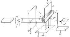
- FIG. 1 is a schematic view schematically showing an example of a method for producing PEEK fiber.
- a laser beam having a spot-like cross section emitted from a laser generation source 1 is used as an optical path adjusting means comprising a beam expander and homogenizer 2, a collimation lens 3, and a cylindrical lens group 4.
- the end portion of the polymer sheet 6 held by the holding member 7 is irradiated to form a belt-like melted portion 6a, and the high voltage generator 10 A voltage is applied to generate a potential difference between the belt-shaped melted part 6a and the fiber collecting plate 8 disposed below the polymer sheet 6.
- the temperature of the belt-shaped melted portion 6a can be observed by the thermography 9, and the conditions such as the voltage and the laser beam to be irradiated can be optimized.
- the holding member 7 that holds the polymer sheet 6 also functions as an electrode.
- the polymer sheet 6 Charge is applied to the band-shaped melted portion 6 a formed by the irradiation of the band-shaped laser beam 5.
- the fiber collecting plate 8 has a surface electrical resistance value comparable to that of a metal. Examples of the shape include a plate shape, a roller shape, a belt shape, a net shape, a saw shape, a wave shape, a needle shape, and a line shape.
- FIG. 2 is a schematic diagram of a tailor cone formed in the belt-shaped melted portion 6a.
- charges are collected and repelled on the surface, thereby gradually forming a plurality of needle-like protrusions (tailor cones) 6b.
- the molten polymer sheet is ejected as fibers from the tip of the tailor cone to the fiber collecting plate 8 by electrostatic attraction, that is, fibers are formed from the needle-like protrusions 6b, and the fibers are collected. Fly in the direction of plate 8. As a result, the elongated fibers are collected by the fiber collecting plate 8.
- the fibers are collected on the collecting member. That is, in the PEEK fiber manufacturing method, the fiber collection plate itself may be a member for collecting fibers, or the collection member may be placed on the fiber collection plate separately from the fiber collection plate.
- the 2 can be adjusted by appropriately changing the thickness of the polymer sheet 6.
- the number of tailor cones shown in FIG. The development of the tailor cone means that the height of the tailor cone (h in FIG. 2) increases.
- the number of tailor cones is not particularly limited, but is preferably 1 to 100, more preferably 1 to 50, and further preferably 2 to 10 per 2 cm in the width direction of the heated and melted portion of the polymer sheet. is there. If the number of tailor cones is 1 to 100 per 2 cm in the width direction, the fiber repulsion between tailor cones will not be reduced, and an appropriate production amount can be secured. it can.
- the laser source examples include a YAG laser, a carbon dioxide (CO 2 ) laser, an argon laser, an excimer laser, and a helium-cadmium laser.
- a carbon dioxide laser is preferred because of its high power efficiency and high PEEK meltability.
- the wavelength of the laser light is preferably 200 nm to 20 ⁇ m, more preferably 500 nm to 18 ⁇ m, and still more preferably 5 to 15 ⁇ m.
- the thickness of the laser beam is preferably 0.5 to 10 mm. If the thickness of the laser beam is less than 0.5 mm, it may be difficult to form a tailor cone. If the thickness exceeds 10 mm, the melt residence time becomes long, and the material may be deteriorated.
- the laser beam output may be controlled so that the temperature of the belt-shaped melted portion is not lower than the melting point of the polymer sheet and not higher than the ignition point of the polymer sheet. From the standpoint of reducing the diameter, a higher value is preferable.
- the specific output of the laser beam can be appropriately selected according to the physical properties (melting point, LOI value (limit oxygen index)) and shape of the polymer sheet to be used, the feeding speed of the polymer sheet, and the like, but preferably 5 to 100 W / 13 cm, more preferably 20 to 60 W / 13 cm, still more preferably 30 to 50 W / 13 cm.
- the output of the laser beam is an output of a spot beam emitted from a laser generation source.
- the temperature of the belt-like melted part is not particularly limited as long as it is not lower than the melting point (334 ° C.) of PEEK and not higher than the ignition point, but is usually about 350 to 600 ° C., preferably 380 to 500 ° C.
- the laser beam is applied to the belt-shaped melted portion (end portion) of the polymer sheet from only one direction.
- the laser beam is applied from two directions via a reflection mirror. You may irradiate the strip
- the potential difference generated between the end of the polymer sheet and the collecting member is preferably a high voltage within a range where no discharge occurs, and the required fiber diameter (diameter), electrode Can be appropriately selected according to the distance between the light source and the collecting member, the irradiation amount of the laser beam, etc., but is usually about 0.1 to 30 kV / cm, preferably 0.5 to 20 kV / cm, more preferably 1 to 10 kV / cm. It is.
- the method of applying a voltage to the melted part of the polymer sheet may be a direct application method in which the laser light irradiation part (the belt-like melted part of the polymer sheet) and the electrode part for applying electric charge are matched.
- the laser beam irradiation part and the charge are given from the point that the device can be easily manufactured, the laser beam can be effectively converted into thermal energy, the reflection direction of the laser beam can be easily controlled, and the safety is high.
- An indirect application method (particularly, a method of providing a laser beam irradiation part on the downstream side in the feeding direction of the polymer sheet) is preferred in which the electrode part is provided at a separate position.
- the polymer sheet is irradiated with a band-shaped laser beam downstream from the electrode unit, and the distance between the electrode unit and the laser beam irradiation unit (for example, the lower end of the electrode unit and the upper side of the band-shaped laser beam) It is preferable to adjust the distance to the outer edge to a specific range (for example, about 10 mm or less).
- This distance can be selected according to the electrical conductivity, thermal conductivity, glass transition point, laser beam irradiation amount, etc. of the polymer sheet, preferably 0.5 to 10 mm, more preferably 1 to 8 mm, and still more preferably 1 .About.5 to 7 mm, particularly preferably about 2 to 5 mm.
- the distance between the two is within this range, the molecular mobility of the resin in the laser light irradiation part is increased, and a sufficient charge can be imparted to the molten resin, so that productivity can be improved.
- the distance between the end of the polymer sheet (the tip of the tailor cone) and the collecting member is not particularly limited, and is usually 5 mm or more, but in order to produce a fiber having a small diameter efficiently,
- the thickness is preferably 10 to 300 mm, more preferably 15 to 200 mm, still more preferably 50 to 150 mm, and particularly preferably 80 to 120 mm.
- the feeding speed when continuously feeding the polymer sheet is preferably 2 to 20 mm / min, more preferably 3 to 15 mm / min, and further preferably 4 to 10 mm / min. Increasing the speed increases the productivity. However, if the speed is too high, the polymer sheet in the laser light irradiation part is not sufficiently melted, making it difficult to manufacture the fiber. On the other hand, when the speed is low, the polymer sheet is decomposed or the productivity is lowered.
- the polymer sheet has a crystallinity of preferably 25% or less, more preferably 20% or less, and still more preferably 15% or less.
- a PEEK fiber having a low crystallinity can be obtained.
- the crystallinity of the polymer sheet can be determined by the same method as the crystallinity of the PEEK fiber.
- the polymer sheet preferably has a low melt viscosity from the viewpoint of easily obtaining a fiber having a small fiber diameter, and has a melt viscosity at a shear rate (shear rate) of 121.6 (1 / s) measured at 400 ° C. It is preferably 800 Pa ⁇ s or less (50 to 800 Pa ⁇ s), more preferably 600 Pa ⁇ s or less, and still more preferably 400 Pa ⁇ s or less.
- the melt viscosity can be determined by a capillary rheometer (trade name “Capillograph 1D”, manufactured by Toyo Seiki Seisakusho Co., Ltd.) by the method described in Examples.
- the shear rate (shear rate) can also be measured using a capillary rheometer.
- the polymer sheet can be produced, for example, by heating and melting chip-like PEEK with a T-die extruder or the like to form a sheet.
- a commercially available product can be used as the chip-like PEEK, and a trade name “VESTAKEEP 1000G” (manufactured by Daicel-Evonik Co., Ltd.) can be preferably used.
- the heating temperature of the T-die extrusion molding machine may be higher than the melting point of PEEK, and is, for example, 350 to 400 ° C.
- the polymer sheet includes various additives used for fibers, such as infrared absorbers, stabilizers (antioxidants, ultraviolet absorbers, heat stabilizers, etc.), flame retardants, antistatic agents, colorants, fillers. , Lubricants, antibacterial agents, insect and acaricides, fungicides, matting agents, heat storage agents, fragrances, fluorescent brighteners, wetting agents, plasticizers, thickeners, dispersants, foaming agents, surfactants, etc. You may contain. These additives can be blended alone or in combination of two or more.
- a surfactant When a charge is injected by applying a high voltage to the polymer sheet, the polymer sheet has high electrical insulation, and it is difficult to inject the charge to the heat melting portion where the electrical resistance is low. However, when a surfactant is used, the electric resistance of the surface of the polymer sheet having a large electrical insulation is lowered, and charges can be sufficiently injected up to the heat melting portion. Also, the application of a surfactant or the like is effective for phase separation when the sheet is composed of a plurality of components when a high voltage is applied to the polymer sheet to inject charges.
- Each of these additives can be used at a ratio of 50 parts by weight or less with respect to 100 parts by weight of the resin constituting the polymer sheet, preferably 0.01 to 30 parts by weight, more preferably 0.1 to 5 parts by weight. It is the ratio of parts by weight.
- the thickness of the polymer sheet is preferably 0.01 to 10 mm, more preferably 0.05 to 5.0 mm. When the thickness is in the above range, the PEEK fiber described later can be easily manufactured.
- the space between the end portion of the polymer sheet and the collecting member may be an inert gas atmosphere.
- the inert gas include nitrogen gas, helium gas, argon gas, carbon dioxide gas, and the like. Of these, nitrogen gas is usually used.
- the use of the inert gas can suppress the oxidation reaction in the belt-like melted portion.
- the space may be heated.
- the diameter of the fiber obtained by heating can be reduced. That is, by heating the air or inert gas in the space, it is possible to suppress a rapid temperature drop of the fiber being formed, thereby promoting the elongation or stretching of the fiber and obtaining a finer fiber. It is done.
- the heating method include a method using a heater (such as a halogen heater) and a method of irradiating a laser beam.
- the heating temperature can be selected from, for example, a temperature range from 50 ° C. or higher to less than the ignition point of the resin, but from the viewpoint of spinnability, a temperature lower than the melting point of PEEK is preferable.
- a method of moving the collection position of the fibers flying in the fiber collecting plate direction with time for example, (1) a collecting member (if the fiber collecting plate itself functions as a collecting member, fibers are used. (2) a method for moving the holding position of the polymer sheet, (3) a mechanical, magnetic or electrical force on the flying fiber from the tailor cone toward the collecting member. For example, a method of applying a force, for example, a method of blowing air onto a flying fiber, (4) a method of selectively combining the methods (1) to (3), or the like can be used.
- the method of (1) above that is, the method of moving the collecting member is easy in that the configuration of the apparatus is easy and the shape (thickness, basis weight, etc.) of the nonwoven fabric to be manufactured can be easily controlled. desirable.
- the manufacturing method of the nonwoven fabric formed from PEEK fiber is explained in full detail for the case where the method of said (1) is used as an example.
- a collecting member is placed on the fiber collecting plate 8.
- the PEEK fiber manufacturing method is continuously performed while moving the collecting member in a direction perpendicular to the width method of the polymer sheet 6 (right direction or left direction in the figure).
- the moving speed of the collecting member may be constant, may change with time, and may be repeatedly moved and stopped.
- the polymer sheet 6 is moved to the fiber collecting plate 8 side (collecting member side) as the fiber manufacturing process proceeds. What is necessary is just to send out continuously.
- rate (feed speed) which sends out a polymer sheet continuously is as having described with the manufacturing method of the said PEEK fiber.
- the moving speed of the collecting member on the fiber collecting plate 8 is not particularly limited, and may be appropriately determined in consideration of the basis weight of the fiber sheet to be manufactured, but is usually about 10 to 2000 mm / min.
- the basis weight is about 0.5 g / m 2 .
- Nonwoven fabrics can be produced continuously.
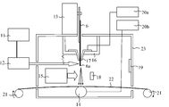
- FIG. 3 is a cross-sectional view schematically showing an example of a nonwoven fabric manufacturing apparatus including the method of manufacturing the PEEK fiber shown in FIG.
- the apparatus (nonwoven fabric manufacturing apparatus) shown in FIG. 3 has a laser source 11, an optical path adjusting member 12, a polymer sheet feeder 13 that can continuously feed the polymer sheet 6, and a holder that holds the polymer sheet 6.
- a member 16 an electrode 17 for applying an electric charge to the polymer sheet 6, a collecting member 22 for collecting fibers, a belt-like melted portion (end portion) 6 a of the electrode 17 and the polymer sheet 6, and a collecting member 22
- a high-voltage generator 20a, 20b for applying a voltage to each of the housing 23 provided with the fiber collecting plate 14 and the heating device 15 disposed opposite to each other, the electrode 17, and the fiber collecting plate 14,
- a pulley 21 for moving the collecting member 22 is provided.
- the optical path adjusting member 12 is an assembly of optical components as described above, and includes the beam expander and homogenizer 2, the collimation lens 3, and the cylindrical lens group 4 shown in FIG.
- the belt-shaped laser light 5 emitted from the laser generation source 11 and passed through the optical path adjusting member 12 is introduced into the housing 23 and irradiated to the belt-shaped melted portion (end portion) 6 a of the polymer sheet 6.
- a polymer sheet feeding device 13 having a motor and a mechanism for converting the rotational motion of the motor into a linear motion is attached to the upper portion of the housing 23.
- the polymer sheet 6 is attached to the polymer sheet feeding device 13. And are continuously fed into the housing 23.
- the lower part of the polymer sheet 6 is held by a holding member 16 to which an electrode 17 is attached. Since the polymer sheet 6 and the electrode 17 are always in contact with each other, a charge is applied to the polymer sheet 6 when a voltage is applied to the electrode 17.
- the fiber collecting plate 14 functioning as an electrode that forms a pair with the electrode 17 is disposed at a position facing the polymer sheet 6 through the belt-shaped melted portion (end portion) 6 a and the collecting member 22. Therefore, when a voltage is applied to the electrode 17 and the fiber collecting plate 14, a potential difference is generated between the belt-shaped melted portion (end portion) 6 a of the polymer sheet 6 and the collecting member 22. .
- the application of voltage to the electrode 17 and the fiber collecting plate 14 is performed by the high voltage generators 20a and 20b connected thereto.
- the electrode 17 is a positive electrode and the fiber collecting plate 14 is a negative electrode.
- the collecting member 22 is a belt conveyor including a pulley 21 and a conveyor belt, and the conveyor belt itself corresponds to the collecting member 22. Therefore, as the pulley 21 is driven, the collecting member 22 (conveyor belt) moves in a predetermined direction (for example, rightward in the figure).
- the nonwoven fabric manufacturing apparatus shown in FIG. 3 includes a heating device 15, and can heat the stretched fibers that are discharged from the belt-shaped melted portion (end portion) 6 a of the polymer sheet 6 toward the collecting member 22. . Further, a laser light absorbing plate 19 and a heat absorbing plate 18 are provided in the housing 23.
- the polymer sheet 6 is fed while the polymer sheet 6 is fed by the polymer sheet feeding device 13 and the holding member 16 in a state where a voltage is applied to both the electrode 17 and the fiber collecting plate 14.
- a tailor cone is formed on the belt-like melted portion (end portion) 6a of the polymer sheet 6 as described above.
- the fibers are discharged and fly to the fiber collecting plate 14, and as a result, the elongated fibers are collected by the collecting member 22.
- the nonwoven fabric can be manufactured on the collection member 22 by moving the collection member 22 while feeding the polymer sheet 6 continuously (discharging fiber continuously).
- the collection member 22 is a sheet-like member.
- the collecting member 22 is not particularly limited as long as it is in the form of a sheet, but is paper, film, various woven fabrics, non-woven fabric, mesh or the like. Further, the collecting member may be a metal or a sheet or a belt having a surface electrical resistance value equivalent to that of a metal.
- the electrode 17 and the fiber collecting plate 14 may be made of a conductive material (usually a metal component).
- a metal component such as chromium or a Group 10 element such as platinum.
- group 11 element such as copper and silver
- group 12 element such as zinc
- group 13 element such as aluminum, simple substance or alloy (aluminum alloy, stainless steel alloy, etc.), or compound containing these metals ( Metal oxides such as silver oxide and aluminum oxide).
- metal components can be used alone or in combination of two or more. Of these metal components, copper, silver, aluminum, stainless steel alloy and the like are particularly preferable.
- the shape of the fiber collecting plate 14 is not particularly limited, and examples thereof include a plate shape, a roller shape, a belt shape, a net shape, a saw shape, a wave shape, a needle shape, and a line shape. Of these shapes, a plate shape and a roller shape are particularly preferable.
- Examples of the laser light absorbing plate 19 include a metal coated with a black body and a porous ceramic.
- Examples of the heat absorbing plate 18 include black ceramic.
- the blood filter of the present invention is manufactured through a step (pressing step) or the like of compressing a non-woven fabric formed from PEEK fiber using, for example, a mold or the like, if necessary, in addition to the above manufacturing method. But you can.
- the blood filter may be integrated by compressing (pressing) a plurality of the nonwoven fabrics.
- Example 1 (Production of polymer sheet) A chip sample of PEEK [manufactured by Daicel-Evonik Co., Ltd., trade name “VESTAKEEP 1000G”] is manufactured with a lab plast mill T die extrusion apparatus (manufactured by Toyo Seiki Seisakusho Co., Ltd.) with a die width of 150 mm and a lip width of 0.4 mm. A T-die is used to extrude into a sheet at an extrusion temperature of 345 to 360 ° C., and is wound up at a take-up roll temperature of 140 ° C. and a winding speed of 1.0 to 2.0 m / min. Produced.
- PEEK manufactured by Daicel-Evonik Co., Ltd., trade name “VESTAKEEP 1000G”
- a T-die is used to extrude into a sheet at an extrusion temperature of 345 to 360 ° C., and is wound up at a take-up roll temperature of 140 ° C.
- the produced polymer sheet had a melt viscosity (400 ° C.) measured by the following method of 151 Pa ⁇ s, and the polymer sheet had a crystallinity of 12.7%.
- the crystallinity of the polymer sheet was determined by the same method as the crystallinity of the PEEK fiber forming the following nonwoven fabric.
- melt viscosity (400 ° C) of polymer sheet The melt viscosity at a shear rate (shear rate) of 121.6 (1 / s) measured at 400 ° C. of the polymer sheet was measured with a capillary rheometer (trade name “Capillograph 1D”, manufactured by Toyo Seiki Seisakusho Co., Ltd.). The measurement was performed using a jig having a capillary diameter of 1 mm and a length of 10 mm.
- a nonwoven fabric formed from PEEK fiber was manufactured by the following method.
- the nonwoven fabric formed from PEEK fiber was manufactured with the nonwoven fabric manufacturing apparatus shown in FIG.
- a CO 2 laser Universal Laser Systems, wavelength 10.6 ⁇ m, output 45 W, air-cooled type, beam diameter ⁇ 4 mm
- a beam expander with a magnification of 2.5 times a homogenizer (incident beam diameter ⁇ 12 mm (design value), output beam diameter ⁇ 12 mm (design value)), and a collimation lens (incident Beam diameter ⁇ 12mm (design value), outgoing beam diameter ⁇ 12mm (design value)), cylindrical lens (plano-concave lens, f-30mm) and cylindrical lens (plano-convex lens, f-300mm) are arranged at predetermined positions in this order We used what we did.
- the spot-shaped laser beam is converted into a band-shaped laser beam 5 having a width of about 150 mm and a thickness of about 1.4 mm, and irradiated to the band-shaped melted portion (end portion) 6 a of the polymer sheet 6. did.
- the output of the laser beam was 61 W / 13 cm
- the feeding speed of the polymer sheet was 6 mm / min
- the potential difference between the electrode 17 and the fiber collecting plate 14 was 6 kV / cm.
- the nonwoven fabric formed from the PEEK fiber whose average fiber diameter (diameter) is 0.7 micrometer was obtained.
- the degree of crystallinity of the PEEK fiber forming the nonwoven fabric by the following measurement method was 24.0%.
- the non-woven fabric produced above was used as a blood filter.
- the average pore diameter of the blood filter was 200 ⁇ m, and the porosity was 60%.
- the degree of crystallinity of the PEEK fiber forming the nonwoven fabric was calculated from the amount of heat obtained from DSC measurement.
- DSC measurement is performed using a differential scanning calorimeter (DSC-Q2000 / TA), using alumina as a reference material, under a nitrogen atmosphere, in a temperature range of 0 to 420 ° C., and at a heating rate of 20 ° C./min. It was.
- the crystallinity was determined from the amount of heat determined by DSC measurement using the following formula.
- Crystallinity (%) ⁇ (heat of fusion of sample [J / g]) ⁇ (heat of recrystallization of sample [J / g]) ⁇ / heat of fusion of complete crystal (130 [J / g]) ⁇ 100
- a blood filter containing a nonwoven fabric made of PEEK fiber [2] The blood filter according to [1], wherein the average pore diameter is 3 to 280 ⁇ m. [3] The blood filter according to [1] or [2], which has a porosity of 15 to 70%. [4] The blood filter according to any one of [1] to [3], wherein an average fiber diameter of the PEEK fiber is 10 ⁇ m or less. [5] The blood filter according to any one of [1] to [4], wherein the basis weight of the nonwoven fabric is 0.02 to 100,000 g / m 2 .
- the blood filter of the present invention has excellent durability, dimensional stability, chemical resistance, and biocompatibility. Therefore, it can be used for the purpose of removing white blood cells, potassium and the like from blood.
Landscapes
- Health & Medical Sciences (AREA)
- Heart & Thoracic Surgery (AREA)
- Engineering & Computer Science (AREA)
- Chemical & Material Sciences (AREA)
- Public Health (AREA)
- Biomedical Technology (AREA)
- Hematology (AREA)
- Life Sciences & Earth Sciences (AREA)
- Animal Behavior & Ethology (AREA)
- General Health & Medical Sciences (AREA)
- Anesthesiology (AREA)
- Veterinary Medicine (AREA)
- Vascular Medicine (AREA)
- Chemical Kinetics & Catalysis (AREA)
- Textile Engineering (AREA)
- Medicinal Chemistry (AREA)
- Polymers & Plastics (AREA)
- Organic Chemistry (AREA)
- Nonwoven Fabrics (AREA)
- Filtering Materials (AREA)
- External Artificial Organs (AREA)
Abstract
Le but de la présente invention est de fournir un filtre sanguin qui : ne présente pas de réduction des propriétés physiques suite à une stérilisation par faisceau d'électrons lorsqu'il est utilisé comme filtre sanguin; présente une excellente durabilité, une excellente stabilité dimensionnelle et une excellente résistance chimique; présente une biocompatibilité; et n'a pas de réduction des propriétés physiques pendant la stérilisation par faisceau d'électrons. Ce filtre sanguin est caractérisé en ce qu'il comprend un tissu non tissé comprenant des fibres PEEK (polyétheréthercétone). Idéalement, ce filtre sanguin a un diamètre de pore moyen de 3 à 280 µm, une porosité de 15 % à 70 %, et un diamètre de fibre moyen pour les fibres PEEK ne dépassant pas 10 µm.
Priority Applications (4)
| Application Number | Priority Date | Filing Date | Title |
|---|---|---|---|
| JP2018558091A JPWO2018117265A1 (ja) | 2016-12-22 | 2017-12-22 | 血液フィルター |
| EP17884518.6A EP3560530A4 (fr) | 2016-12-22 | 2017-12-22 | Filtre sanguin |
| US16/472,706 US11419970B2 (en) | 2016-12-22 | 2017-12-22 | Blood filter |
| US17/866,214 US20220347367A1 (en) | 2016-12-22 | 2022-07-15 | Blood filter |
Applications Claiming Priority (2)
| Application Number | Priority Date | Filing Date | Title |
|---|---|---|---|
| JP2016249369 | 2016-12-22 | ||
| JP2016-249369 | 2016-12-22 |
Related Child Applications (2)
| Application Number | Title | Priority Date | Filing Date |
|---|---|---|---|
| US16/472,706 A-371-Of-International US11419970B2 (en) | 2016-12-22 | 2017-12-22 | Blood filter |
| US17/866,214 Continuation US20220347367A1 (en) | 2016-12-22 | 2022-07-15 | Blood filter |
Publications (1)
| Publication Number | Publication Date |
|---|---|
| WO2018117265A1 true WO2018117265A1 (fr) | 2018-06-28 |
Family
ID=62626662
Family Applications (1)
| Application Number | Title | Priority Date | Filing Date |
|---|---|---|---|
| PCT/JP2017/046237 Ceased WO2018117265A1 (fr) | 2016-12-22 | 2017-12-22 | Filtre sanguin |
Country Status (4)
| Country | Link |
|---|---|
| US (2) | US11419970B2 (fr) |
| EP (1) | EP3560530A4 (fr) |
| JP (1) | JPWO2018117265A1 (fr) |
| WO (1) | WO2018117265A1 (fr) |
Families Citing this family (1)
| Publication number | Priority date | Publication date | Assignee | Title |
|---|---|---|---|---|
| WO2018117265A1 (fr) * | 2016-12-22 | 2018-06-28 | 株式会社ダイセル | Filtre sanguin |
Citations (3)
| Publication number | Priority date | Publication date | Assignee | Title |
|---|---|---|---|---|
| JP2010094962A (ja) * | 2008-10-20 | 2010-04-30 | Unitika Ltd | 微細繊維集合体の積層体及び分離膜 |
| JP2013534462A (ja) | 2010-06-03 | 2013-09-05 | ディーエスエム アイピー アセッツ ビー.ブイ. | 血液濾過に適した膜 |
| WO2014196651A1 (fr) | 2013-06-07 | 2014-12-11 | 日産化学工業株式会社 | Filtre pour le sang et procédé pour le produire |
Family Cites Families (26)
| Publication number | Priority date | Publication date | Assignee | Title |
|---|---|---|---|---|
| NL8802888A (nl) * | 1988-11-23 | 1990-06-18 | Akzo Nv | Filter en werkwijze voor het vervaardigen van een leucocytenarme trombocytensuspensie. |
| JP3172542B2 (ja) * | 1990-06-25 | 2001-06-04 | テルモ株式会社 | 白血球捕捉用フィルター材及びその製造方法 |
| JP2986860B2 (ja) | 1990-07-03 | 1999-12-06 | グンゼ株式会社 | 骨固定用具 |
| US5264274A (en) | 1991-02-04 | 1993-11-23 | Honda Giken Kogyo Kabushiki Kaisha | Thermoplastic composite material having improved toughness and method of producing same |
| ATE197547T1 (de) * | 1991-08-22 | 2000-12-15 | Asahi Medical Co | Filtermedium zur selektiven entfernung von leukozyten und entsprechende vorrichtung |
| US5601714A (en) * | 1994-06-30 | 1997-02-11 | Polystan Holding A/S | Device for filtration and collection of blood |
| WO2003073912A2 (fr) | 2002-02-28 | 2003-09-12 | Wm. Marsh Rice University | Plot prefabrique a base de tissus |
| CN100512891C (zh) * | 2002-12-02 | 2009-07-15 | 旭化成医疗株式会社 | 用于去除白细胞的方法、白细胞除去过滤器及其使用 |
| US20050038498A1 (en) | 2003-04-17 | 2005-02-17 | Nanosys, Inc. | Medical device applications of nanostructured surfaces |
| US7439291B2 (en) * | 2005-09-14 | 2008-10-21 | General Electric Company | Solvent-resistant membranes from solvent-inert polyimides and polyketones |
| JP4838084B2 (ja) | 2006-09-28 | 2011-12-14 | タピルス株式会社 | ポリエーテルエーテルケトン製メルトブロー不織布、その製造方法及びそれからなる耐熱性電池セパレータ |
| WO2010099333A2 (fr) | 2009-02-25 | 2010-09-02 | Porex Surgical, Inc. | Structures de retenue d'un matériau de greffe osseuse |
| JP5608943B2 (ja) * | 2009-03-31 | 2014-10-22 | マイクロ化学技研株式会社 | 血漿分離装置及び方法 |
| WO2012057029A1 (fr) * | 2010-10-25 | 2012-05-03 | 株式会社カネカ | Nouveau filtre d'élimination des leucocytes |
| US9649427B2 (en) * | 2011-12-28 | 2017-05-16 | Xerem Medical Ltd. | System and method for blood filtering and/or treatment |
| NZ623463A (en) * | 2012-01-25 | 2016-05-27 | Fresenius Hemocare Italia Srl | Blood filter, system and use of a blood filter or system |
| PL2809433T3 (pl) * | 2012-01-27 | 2018-04-30 | Zeus Industrial Products, Inc. | Elektroprzędzone porowate media |
| EP3950019A1 (fr) | 2013-03-15 | 2022-02-09 | Nanofiber Solutions, LLC | Textiles biocompatibles à base de fibres destinés à être implantés |
| US20150211160A1 (en) | 2014-01-29 | 2015-07-30 | Biax-Fiberfilm | High loft, nonwoven web exhibiting excellent recovery |
| DE102014202578A1 (de) | 2014-02-12 | 2015-08-13 | Aesculap Ag | Medizinisches Produkt und Verfahren zu seiner Herstellung |
| JP5807885B1 (ja) | 2014-09-24 | 2015-11-10 | 圓井繊維機械株式会社 | 骨固定具、及びその製造方法 |
| JP6496120B2 (ja) * | 2014-10-20 | 2019-04-03 | 株式会社ダイセル | 高融点樹脂ファイバー及び不織布 |
| JP2016121421A (ja) * | 2014-12-25 | 2016-07-07 | 株式会社ダイセル | Peek樹脂ファイバーの製造方法、peek樹脂ファイバー及び不織布 |
| JP6411900B2 (ja) * | 2015-01-21 | 2018-10-24 | 株式会社ダイセル | Peekファイバーの製造方法、peekファイバー及び不織布 |
| JP6470978B2 (ja) | 2015-01-22 | 2019-02-13 | 株式会社ダイセル | 生体インプラントの製造方法 |
| WO2018117265A1 (fr) * | 2016-12-22 | 2018-06-28 | 株式会社ダイセル | Filtre sanguin |
-
2017
- 2017-12-22 WO PCT/JP2017/046237 patent/WO2018117265A1/fr not_active Ceased
- 2017-12-22 US US16/472,706 patent/US11419970B2/en active Active
- 2017-12-22 JP JP2018558091A patent/JPWO2018117265A1/ja active Pending
- 2017-12-22 EP EP17884518.6A patent/EP3560530A4/fr active Pending
-
2022
- 2022-07-15 US US17/866,214 patent/US20220347367A1/en not_active Abandoned
Patent Citations (3)
| Publication number | Priority date | Publication date | Assignee | Title |
|---|---|---|---|---|
| JP2010094962A (ja) * | 2008-10-20 | 2010-04-30 | Unitika Ltd | 微細繊維集合体の積層体及び分離膜 |
| JP2013534462A (ja) | 2010-06-03 | 2013-09-05 | ディーエスエム アイピー アセッツ ビー.ブイ. | 血液濾過に適した膜 |
| WO2014196651A1 (fr) | 2013-06-07 | 2014-12-11 | 日産化学工業株式会社 | Filtre pour le sang et procédé pour le produire |
Also Published As
| Publication number | Publication date |
|---|---|
| US20200129688A1 (en) | 2020-04-30 |
| JPWO2018117265A1 (ja) | 2019-12-12 |
| US11419970B2 (en) | 2022-08-23 |
| EP3560530A4 (fr) | 2020-08-19 |
| US20220347367A1 (en) | 2022-11-03 |
| EP3560530A1 (fr) | 2019-10-30 |
Similar Documents
| Publication | Publication Date | Title |
|---|---|---|
| KR102401754B1 (ko) | 고융점 수지 섬유 및 부직포 | |
| JP5311455B2 (ja) | 紡糸方法並びにそれを用いた繊維製造方法及び装置 | |
| US20100297443A1 (en) | Ultrafine composite fiber, ultrafine fiber, method for manufacturing same, and fiber structure | |
| WO2007105479A1 (fr) | Procede de filage electrostatique a l'etat fondu et fibre extra fine | |
| JP6411900B2 (ja) | Peekファイバーの製造方法、peekファイバー及び不織布 | |
| JPWO2010027063A1 (ja) | 繊維集合物、導電性基材と繊維集合物との複合体及びそれらの製造方法 | |
| JP5540293B2 (ja) | 紡糸方法、繊維マットの製造方法、紡糸装置、繊維、及び、繊維マット | |
| JP6470978B2 (ja) | 生体インプラントの製造方法 | |
| JP2010275663A (ja) | 繊維集合物及び熱接着不織布の製造方法 | |
| JP2016121421A (ja) | Peek樹脂ファイバーの製造方法、peek樹脂ファイバー及び不織布 | |
| JP5804344B2 (ja) | 繊維マットの製造方法、及び、繊維マット | |
| JP5593038B2 (ja) | 極細複合繊維及びその製造方法、並びに繊維構造物 | |
| US20220347367A1 (en) | Blood filter | |
| JP2018104828A (ja) | 強化用繊維、不織布、及び繊維強化樹脂 | |
| JP7019290B2 (ja) | 電解質膜補強材及び電解質膜 | |
| JP2013064203A (ja) | ナノファイバーよりなる連続シートの製造方法 | |
| US11344653B2 (en) | Bone fixing material | |
| JP2020117097A (ja) | 航空機用部材、及びその製造方法 | |
| JP2011106041A (ja) | シートの製造方法、およびシートの製造装置 | |
| JP6871696B2 (ja) | 不織布シート、細胞培養足場材、及び、不織布シートの製造方法 | |
| JP5467895B2 (ja) | 繊維集合物及びその製造方法 | |
| JP2010270423A (ja) | 極細繊維の製造方法 | |
| JP2005097753A (ja) | 繊維シートの製造方法 | |
| JP2013159870A (ja) | 微細熱可塑性繊維の製造方法 |
Legal Events
| Date | Code | Title | Description |
|---|---|---|---|
| 121 | Ep: the epo has been informed by wipo that ep was designated in this application |
Ref document number: 17884518 Country of ref document: EP Kind code of ref document: A1 |
|
| ENP | Entry into the national phase |
Ref document number: 2018558091 Country of ref document: JP Kind code of ref document: A |
|
| NENP | Non-entry into the national phase |
Ref country code: DE |
|
| ENP | Entry into the national phase |
Ref document number: 2017884518 Country of ref document: EP Effective date: 20190722 |