WO2018123574A1 - Support de piles - Google Patents
Support de piles Download PDFInfo
- Publication number
- WO2018123574A1 WO2018123574A1 PCT/JP2017/044638 JP2017044638W WO2018123574A1 WO 2018123574 A1 WO2018123574 A1 WO 2018123574A1 JP 2017044638 W JP2017044638 W JP 2017044638W WO 2018123574 A1 WO2018123574 A1 WO 2018123574A1
- Authority
- WO
- WIPO (PCT)
- Prior art keywords
- battery
- safety valve
- exhaust duct
- battery module
- exhaust
- Prior art date
- Legal status (The legal status is an assumption and is not a legal conclusion. Google has not performed a legal analysis and makes no representation as to the accuracy of the status listed.)
- Ceased
Links
Images



Classifications
-
- H—ELECTRICITY
- H01—ELECTRIC ELEMENTS
- H01M—PROCESSES OR MEANS, e.g. BATTERIES, FOR THE DIRECT CONVERSION OF CHEMICAL ENERGY INTO ELECTRICAL ENERGY
- H01M50/00—Constructional details or processes of manufacture of the non-active parts of electrochemical cells other than fuel cells, e.g. hybrid cells
- H01M50/30—Arrangements for facilitating escape of gases
- H01M50/342—Non-re-sealable arrangements
- H01M50/3425—Non-re-sealable arrangements in the form of rupturable membranes or weakened parts, e.g. pierced with the aid of a sharp member
-
- H—ELECTRICITY
- H01—ELECTRIC ELEMENTS
- H01M—PROCESSES OR MEANS, e.g. BATTERIES, FOR THE DIRECT CONVERSION OF CHEMICAL ENERGY INTO ELECTRICAL ENERGY
- H01M10/00—Secondary cells; Manufacture thereof
- H01M10/04—Construction or manufacture in general
- H01M10/0422—Cells or battery with cylindrical casing
-
- H—ELECTRICITY
- H01—ELECTRIC ELEMENTS
- H01M—PROCESSES OR MEANS, e.g. BATTERIES, FOR THE DIRECT CONVERSION OF CHEMICAL ENERGY INTO ELECTRICAL ENERGY
- H01M50/00—Constructional details or processes of manufacture of the non-active parts of electrochemical cells other than fuel cells, e.g. hybrid cells
- H01M50/20—Mountings; Secondary casings or frames; Racks, modules or packs; Suspension devices; Shock absorbers; Transport or carrying devices; Holders
- H01M50/204—Racks, modules or packs for multiple batteries or multiple cells
-
- H—ELECTRICITY
- H01—ELECTRIC ELEMENTS
- H01M—PROCESSES OR MEANS, e.g. BATTERIES, FOR THE DIRECT CONVERSION OF CHEMICAL ENERGY INTO ELECTRICAL ENERGY
- H01M50/00—Constructional details or processes of manufacture of the non-active parts of electrochemical cells other than fuel cells, e.g. hybrid cells
- H01M50/20—Mountings; Secondary casings or frames; Racks, modules or packs; Suspension devices; Shock absorbers; Transport or carrying devices; Holders
- H01M50/204—Racks, modules or packs for multiple batteries or multiple cells
- H01M50/207—Racks, modules or packs for multiple batteries or multiple cells characterised by their shape
- H01M50/213—Racks, modules or packs for multiple batteries or multiple cells characterised by their shape adapted for cells having curved cross-section, e.g. round or elliptic
-
- H—ELECTRICITY
- H01—ELECTRIC ELEMENTS
- H01M—PROCESSES OR MEANS, e.g. BATTERIES, FOR THE DIRECT CONVERSION OF CHEMICAL ENERGY INTO ELECTRICAL ENERGY
- H01M50/00—Constructional details or processes of manufacture of the non-active parts of electrochemical cells other than fuel cells, e.g. hybrid cells
- H01M50/30—Arrangements for facilitating escape of gases
- H01M50/317—Re-sealable arrangements
-
- H—ELECTRICITY
- H01—ELECTRIC ELEMENTS
- H01M—PROCESSES OR MEANS, e.g. BATTERIES, FOR THE DIRECT CONVERSION OF CHEMICAL ENERGY INTO ELECTRICAL ENERGY
- H01M50/00—Constructional details or processes of manufacture of the non-active parts of electrochemical cells other than fuel cells, e.g. hybrid cells
- H01M50/50—Current conducting connections for cells or batteries
- H01M50/502—Interconnectors for connecting terminals of adjacent batteries; Interconnectors for connecting cells outside a battery casing
-
- Y—GENERAL TAGGING OF NEW TECHNOLOGICAL DEVELOPMENTS; GENERAL TAGGING OF CROSS-SECTIONAL TECHNOLOGIES SPANNING OVER SEVERAL SECTIONS OF THE IPC; TECHNICAL SUBJECTS COVERED BY FORMER USPC CROSS-REFERENCE ART COLLECTIONS [XRACs] AND DIGESTS
- Y02—TECHNOLOGIES OR APPLICATIONS FOR MITIGATION OR ADAPTATION AGAINST CLIMATE CHANGE
- Y02E—REDUCTION OF GREENHOUSE GAS [GHG] EMISSIONS, RELATED TO ENERGY GENERATION, TRANSMISSION OR DISTRIBUTION
- Y02E60/00—Enabling technologies; Technologies with a potential or indirect contribution to GHG emissions mitigation
- Y02E60/10—Energy storage using batteries
Definitions
- This disclosure relates to a battery module.
- Patent Document 1 discloses a battery module that includes a battery provided with a safety valve therein, a connection plate including a gas rectifier that guides gas ejected from the battery in one direction, and an exhaust duct. Yes. Patent Document 1 describes that the gas rectifying portion of the connection plate is bent toward the exhaust duct when gas is ejected from the battery, and becomes a rectifying plate that guides the gas in one direction.
- the safety valve may be provided on the outer surface of the battery case. Even in a battery module equipped with such a battery, it is an important issue to control the opening direction of the safety valve so that the gas ejected from the battery is smoothly exhausted from the outlet of the exhaust duct by opening the safety valve. is there.
- rupture part surrounding a safety valve in C shape for example and controlling the valve opening direction of a safety valve is also considered, in this case, when manufacturing a battery module, each direction so that a safety valve may be aligned. It is necessary to place a battery.
- An object of the present disclosure is to provide a battery module capable of opening the safety valve of each battery in the direction of the outlet of the exhaust duct without adjusting the direction of each battery with respect to the outlet of the exhaust duct.
- the battery module according to the present disclosure includes a plurality of batteries each having a safety valve surrounded by an annular break portion that breaks when a battery internal pressure exceeds a predetermined value, and a gas ejected from the battery when the safety valve is opened
- An exhaust duct that leads the outside of the module, and a member that is provided between each of the batteries and the exhaust duct, and has a plurality of openings that expose the safety valves, and the exhaust duct of the safety valves.
- an exhaust direction defining member that protrudes in a range overlapping each of the safety valves so as to cover an end located on the opposite side of the outlet side end.
- the safety valve of each battery can be opened in the direction of the outlet of the exhaust duct without adjusting the direction of each battery with respect to the outlet of the exhaust duct. According to the battery module according to the present disclosure, the gas ejected from the battery when the safety valve is opened can be smoothly exhausted from the outlet of the exhaust duct.
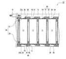
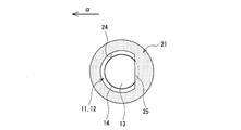
- FIG. 2 It is sectional drawing of the battery module which is an example of embodiment. It is a top view of the battery module which is an example of embodiment, and is a figure showing the portion corresponding to one battery. In FIG. 2, it is a figure which shows the state which removed the positive electrode current collecting plate. It is a principal part enlarged view of FIG. 1, Comprising: It is a figure which shows the state which the safety valve of the battery opened. It is a figure which shows another example of embodiment. It is a figure which shows another example of embodiment.
- the end of the safety valve of the battery that is located on the side opposite to the end on the outlet side of the exhaust duct (hereinafter referred to as the “opposite end”) is covered.
- the exhaust direction regulating member protrudes.
- the opposite end portion of the safety valve is pressed from the outside of the battery by the portion (hereinafter, referred to as “saddle”) that covers the safety valve of the exhaust direction regulating member. Is easily opened in the direction of the outlet of the exhaust duct.
- the valve opening direction of the safety valve can be controlled, the gas ejected from the battery can be smoothly exhausted from the outlet of the exhaust duct.
- the battery module according to an aspect of the present disclosure includes at least one selected from, for example, a current collector plate, an insulating plate, and a battery holder as an exhaust direction defining member.
- these members are provided so as not to interfere with the safety valve.
- a part of these members actively interferes with a part of the safety valve. Defines the opening direction of the safety valve.
- the lead part of the current collector plate is extended from the side opposite to the outlet of the exhaust duct to a range that overlaps the safety valve, the lead part does not hinder the opening of the safety valve, and smoother exhaust becomes possible. .
- the cylindrical battery 11 is exemplified as the battery mounted on the battery module, but the battery is not limited to this.
- the direction along the axial direction of the cylindrical battery 11 is the vertical direction of the battery module, and the exhaust duct 15 side is the top.
- FIG. 1 is a cross-sectional view of a battery module 10 which is an example of an embodiment.
- the battery module 10 includes a plurality of cylindrical batteries 11.
- the cylindrical battery 11 has a safety valve 13 surrounded by an annular break portion 14 that breaks when the battery internal pressure exceeds a predetermined value.
- the battery module 10 is provided between an exhaust duct 15 that guides gas ejected from the cylindrical battery 11 to the outside of the module when the safety valve 13 of the cylindrical battery 11 is opened, and between each cylindrical battery 11 and the exhaust duct 15. And an exhaust direction regulating member.
- the exhaust direction defining member has a plurality of openings that expose the respective safety valves 13 of the respective cylindrical batteries 11, and is located on the opposite side of the safety valve 13 from the outlet side end of the exhaust duct 15. Are overhanging the safety valve 13 so as to cover the end portion.
- the battery module 10 includes a resin battery holder 20 that holds a plurality of cylindrical batteries 11.
- the battery holder 20 is provided with a plurality of accommodating portions 23 for accommodating the respective cylindrical batteries 11.
- the battery module 10 may have one or a plurality of battery blocks including one battery holder 20.
- a metal battery holder may be used.
- the battery module 10 includes, for example, a pair of current collector plates (a positive current collector plate 30 and a negative current collector plate 40) that connect a plurality of cylindrical batteries 11 accommodated in one battery holder 20 in parallel.
- a pair of current collector plates a positive current collector plate 30 and a negative current collector plate 40
- the battery blocks are connected in series.
- the exhaust duct 15 may be connected by a plurality of battery blocks, but is preferably separated for each block.
- the battery module 10 includes an exhaust duct 15, a positive current collector 30, a plurality of cylindrical batteries 11 accommodated in a battery holder 20, and a negative current collector 40 in order from the top.
- a safety valve 13 is provided on one end surface of each cylindrical battery 11 in the axial direction, and each cylindrical battery 11 is arranged so that one end surface in the axial direction faces upward.
- the battery holder 20 and the positive electrode current collector plate 30 are formed with a plurality of openings 24 and 34 that expose the safety valves 13, respectively, and the openings 24 and 34 secure an exhaust path from the safety valve 13 to the exhaust duct 15. Has been.
- the cylindrical battery 11 includes a battery case 12 made of metal such as iron and a power generation element housed in the case.
- the power generation element includes, for example, an electrode body having a winding structure and a nonaqueous electrolyte.
- An example of the cylindrical battery 11 is a lithium ion secondary battery.
- the battery case 12 includes a bottomed cylindrical case main body that houses a power generation element, and a sealing plate that closes an opening of the case main body. In the present embodiment, it is assumed that the sealing plate functions as the positive terminal of the cylindrical battery 11 and the safety valve 13 is provided on the sealing plate.
- the side surface of the case body may be covered with an insulating resin film, and in this case, the lower end surface of the case body functions as a negative electrode terminal.
- the battery holder 20 includes a first holder 21 that holds the upper end portion of each cylindrical battery 11 and a second holder 22 that holds the lower end portion of each cylindrical battery 11, and is configured by connecting them. Yes.
- the accommodating portion 23 is formed by the concave portion 23 a of the first holder 21 and the concave portion 23 b of the second holder 22.
- the upper end of the cylindrical battery 11 is inserted into the recess 23a, and the lower end of the cylindrical battery 11 is inserted into the recess 23b.
- the plurality of accommodating portions 23 may be arranged in a zigzag manner or in a lattice shape.
- the first holder 21 functions as the exhaust direction regulating member that controls the opening direction of the safety valve 13.
- the first holder 21 and the second holder 22 are tray-like members in which a plurality of concave portions 23a and 23b are formed, for example.
- the first holder 21 covers the peripheral edge of the upper end surface of each cylindrical battery 11 and holds the upper end of each cylindrical battery 11.
- a plurality of openings 24 are formed in the first holder 21.
- the second holder 22 covers the periphery of the lower end surface of each cylindrical battery 11 and holds the lower end of each cylindrical battery 11. Similar to the first holder 21, a plurality of openings 26 are formed in the second holder 22.
- the battery holder 20 is made of, for example, a curable resin.
- a curable resin include thermosetting resins such as unsaturated polyesters, epoxy resins, melamine resins, and phenol resins.
- the curable resin may contain an endothermic filler such as aluminum hydroxide or sodium hydrogen carbonate, or a thermally conductive filler such as a metal oxide or metal nitride.
- a metal battery holder and a resin insulating plate may be used. In this case, the same configuration as the first holder 21 can be applied to the insulating plate disposed above each cylindrical battery 11 except for the battery holding function.
- the positive electrode current collector plate 30 has a plurality of lead portions 33 respectively connected to the safety valves 13 of the cylindrical batteries 11. As described above, since the sealing plate including the safety valve 13 functions as a positive electrode terminal in the present embodiment, the positive electrode of the cylindrical battery 11 and the positive electrode current collector plate 30 are connected by connecting the lead portion 33 to the safety valve 13. Electrically connected.
- the positive electrode current collector plate 30 is disposed in a state where a portion excluding the lead portion 33 overlaps the first holder 21 and the opening portion 34 overlaps the opening portion 24 of the first holder 21 in the vertical direction. Although described later in detail, the positive electrode current collector plate 30 functions as the exhaust direction regulating member that controls the valve opening direction of the safety valve 13.
- the positive electrode current collecting plate 30 is preferably composed of a base plate 31 and a lead plate 32 including a plurality of lead portions 33.
- the lead plate 32 is bonded to, for example, the lower surface of the base plate 31, and the portion excluding the lead portion 33 overlaps the base plate 31.
- the thickness of the base plate 31 is, for example, 0.5 mm to 1.5 mm
- the thickness of the lead plate 32 is, for example, 0.1 mm to 0.5 mm
- the thickness of the safety valve 13 is, for example, 0.3 mm to 1.0 mm. It is.
- the negative electrode current collector plate 40 has a plurality of lead portions 43 respectively connected to the lower end surface of each battery case 12 and is electrically connected to the negative electrode of the cylindrical battery 11.
- the negative electrode current collector plate 40 is disposed in a state where a portion excluding the lead portion 43 overlaps with the second holder 22 of the battery holder 20 and the opening portion 36 overlaps with the opening portion 26 of the second holder 22 in the vertical direction. ing.
- the negative electrode current collector plate 40 is preferably composed of a base plate 41 and a lead plate 42 including a plurality of lead portions 43.
- FIG. 2 is a plan view of the battery module 10 and shows a portion corresponding to one cylindrical battery 11.
- FIG. 3 is a diagram illustrating a state in which the positive electrode current collector plate 30 is removed from FIG. 2 and 3, the exhaust direction in the exhaust duct 15 is indicated by an arrow ⁇ .
- FIG. 4 is a view showing a state in which the safety valve 13 is opened.
- a single safety valve 13 surrounded by an annular fracture portion 14 is formed on the upper end surface (one axial end surface) of the cylindrical battery 11.
- the annular fracture portion 14 is, for example, a sealing plate or a groove formed on the outside of the case body, and is more than the other portion of the battery case 12 when the internal pressure rises due to an abnormality occurring in the cylindrical battery 11. Break preferentially.
- the groove of the rupture portion 14 is generally called an inscription, and is formed by pressing the sealing plate of the battery case 12 or the case body.
- the portion of the sealing plate where the broken portion 14 is formed becomes a thin portion having a thickness smaller than that of the other portion.
- the safety valve 13 may have an elliptical shape or a polygonal shape in plan view, but preferably has a perfect circle shape in plan view.
- the fracture portion 14 is formed in an annular shape having a substantially constant diameter around the center of the upper end surface of the cylindrical battery 11, and the safety valve 13 is provided at the center portion of the upper end surface of the cylindrical battery 11.
- the safety valve 13 is opened outside the cylindrical battery 11, an opening is formed in the sealing plate, and gas is ejected from the opening.
- the exhaust duct 15 is a space in contact with the safety valve 13 through each opening of the first holder 21 and the positive electrode current collector plate 30 and is formed above each cylindrical battery 11.
- the exhaust duct 15 is formed, for example, between the wall of the module case that houses the battery holder 20 and the positive electrode current collector plate 30.
- the exhaust duct 15 may be provided by attaching a cover or the like that forms an exhaust space on the positive electrode current collector plate 30.
- the exhaust duct 15 is provided only at the upper part of the battery module 10. However, when the safety valve 13 is formed on the lower end surface of the cylindrical battery 11, the exhaust duct is provided below each cylindrical battery 11. Is provided.
- the outlet 16 of the exhaust duct 15 opens in one direction of the battery module 10 so that the exhaust direction of the gas ejected from each cylindrical battery 11 is the same direction.
- the outlet 16 of the exhaust duct 15 is formed at one end in the longitudinal direction of the battery holder 20.
- the outlet 16 is an opening formed in one place such as a module case or a cover that constitutes the exhaust duct 15, for example.
- the first holder 21 and the positive electrode current collector plate 30 functioning as the exhaust direction regulating member are provided between the cylindrical batteries 11 and the exhaust duct 15 as described above, and a plurality of openings that expose the safety valves 13. It has parts 24 and 34, respectively. Each of the openings 24 and 34 is formed for each cylindrical battery 11 and overlaps each other in the vertical direction to expose the safety valves 13. Each opening 24, 34 enables each safety valve 13 to be opened, and serves as an exhaust path leading from each safety valve 13 to the exhaust duct 15. Each opening 24 enables connection between the lead portion 33 and the sealing plate.
- the first holder 21 and the positive electrode current collector plate 30 project from the safety valve 13 so as to cover the end of the exhaust duct 15 on the side opposite to the end on the outlet 16 side so as to overlap each safety valve 13. , 35 respectively.
- the flanges 25 and 35 that cover the safety valve 13 of the first holder 21 and the positive electrode current collector plate 30 (portions overhanging on the safety valve 13) allow a part of the safety valve 13 to be connected to the battery when the internal pressure of the cylindrical battery 11 rises.
- the safety valve 13 is pressed from the outside so that it does not open greatly on the flanges 25 and 35 side.
- the portion located on the outlet 16 side of the safety valve 13 is exposed without being covered by the first holder 21 and the positive electrode current collector plate 30.
- the flange portion 25 substantially abuts on the safety valve 13, for example, and restricts displacement due to opening of the safety valve 13.
- the opening 34 and the flange 35 are formed in, for example, two metal plates (base plate 31 and lead plate 32) constituting the positive electrode current collector plate 30.
- the flange portion 25 and the flange portion 35 of the base plate 31 have substantially the same shape and the same dimensions.
- the flange portion 25 and the flange portion 35 of the base plate 31 are overlapped in the vertical direction with their ends aligned.
- the opening 24 and the opening 34 of the base plate 31 also have substantially the same shape and the same dimensions as each other, and overlap each other in the vertical direction with their edges aligned.
- the lead plate 32 only the lead portion 33 may protrude from the safety valve 13, and the portion other than the lead portion 33 may have the same shape as the base plate 31.
- the lead portion 33 extends from the side opposite to the outlet 16 of the exhaust duct 15 to a range overlapping the safety valve 13 in the vertical direction.
- the lead portion 33 extends on the safety valve 13 from the end portion 180 ° opposite to the end portion closest to the outlet 16 with the center of the safety valve 13 as the center with respect to the exhaust direction in the exhaust duct 15, for example.
- the lead portion 33 is formed in a strip shape that is long in the exhaust direction, and is welded to the central portion of the safety valve 13. In this case, the lead portion 33 may contribute to control of the opening direction of the safety valve 13 as a part of the flange portion 35.
- the lead portion 33 When the lead portion 33 extends from the outlet 16 side of the safety valve 13 onto the safety valve 13, or when the lead portion 33 is thin and the safety valve 13 cannot be pressed from the outside when the internal pressure of the battery increases, the lead portion 33 Does not function as an exhaust direction regulating member.
- the collar portion may be formed only on one of the first holder 21 and the positive electrode current collector plate 30, but when the collar portion is formed only on the positive electrode current collector plate 30, the base is thicker than at least the lead plate 32. It is preferable to form a flange on the plate 31.
- the ends of the flange portion 25 and the flange portion 35 of the base plate 31 are linearly formed.
- the flange portion 25 and the flange portion 35 of the base plate 31 are contoured by a circular arc and a straight line connecting both ends thereof, and may be substantially semicircular, for example.
- the opening 24 and the opening 34 of the base plate 31 are also contoured by an arc and a straight line connecting both ends thereof, and may be, for example, substantially semicircular.
- the flange portions 25 and 35 cover 15% to 50% of the entire length of the fracture portion 14.
- the flange portions 25 and 35 are, for example, 20% of the total length of the fracture portion 14 in a half region of the safety valve 13 located on the opposite side to the outlet 16 side of the exhaust duct 15 (hereinafter sometimes referred to as “opposite side region”). It overhangs to cover 50% to 50%.
- the fracture portion 14 is not covered by the flange portions 25 and 35 and is exposed. Preferably it is.
- the flange portions 25 and 35 project on the safety valve 13 so as to cover, for example, 2.5% to 50%, preferably 10% to 25%, of the area of the safety valve 13. As for the opposite region, the flange portions 25 and 35 cover 10% to 100%, preferably 20% to 50%, of the area of the region.
- the positive electrode current collector plate 30 does not cover the outlet side region.
- a part of the lead part 33 may exist on the outlet side region of the safety valve 13. It is preferable that 50% or more of the area of the safety valve 13 is exposed by the openings 24 and 34.
- the safety valve 13 is positioned on the side opposite to the end on the outlet 16 side of the exhaust duct 15 by the flanges 25 and 35 of the first holder 21 and the positive electrode current collector plate 30. The end is pressed from the outside of the cylindrical battery 11. For this reason, the safety valve 13 does not open to the side opposite to the outlet 16 but easily opens to the outlet 16 side. Since the opening direction of the safety valve 13 can be controlled in this way, the gas ejected from the cylindrical battery 11 can be smoothly exhausted from the outlet 16 of the exhaust duct 15. Further, in the control of the valve opening direction, it is not necessary to adjust the direction of each cylindrical battery 11 with respect to the outlet 16 of the exhaust duct 15.
- the lead portion 33 extends from the opposite side of the outlet 16 of the exhaust duct 15 to the range where it overlaps the safety valve 13. Therefore, the lead portion 33 does not prevent the safety valve 13 from being opened, and smoother exhaust is achieved. It becomes possible. Further, since the flange portion 25 of the first holder 21 is substantially in contact with the safety valve 13, the safety valve 13 can be more reliably prevented from opening in the direction opposite to the outlet 16. Moreover, since the edge of the collar parts 25 and 35 is formed in linear form, the safety valve 13 bends along the edge of the collar parts 25 and 35, for example, and a valve opening state is stabilized.
- positive current collectors 30X and 30Y which are modifications of the positive current collector 30, respectively.
- the positive electrode current collector plates 30X and 30Y have openings 34X and 34Y and flange portions 35X and 35Y.
- a resin battery holder or an insulating plate is disposed between the positive electrode current collector plates 30X and 30Y and the cylindrical battery 11, a resin battery holder or an insulating plate is disposed, and the positive electrode current collector plates 30X and 30Y, except for the lead portion 33, are also provided. It is preferable that the same opening part and collar part are formed.
- the lead plate 32 can be the same as that of the positive electrode current collector plate 30, but a lead plate having a shape corresponding to the base plates 31X and 31Y of the positive electrode current collector plates 30X and 30Y may be used.
- the structure of the positive electrode current collecting plates 30, 30X, and 30Y is applied to, for example, the negative electrode current collecting plate when a safety valve is provided on the negative electrode current collecting plate side.
- the opening 34 ⁇ / b> X has an elliptical shape in plan view, and the flange portion 35 ⁇ / b> X has a crescent shape in plan view.
- the ellipse of the opening 34X has a major axis in the direction orthogonal to the exhaust direction in the exhaust duct 15 indicated by the arrow ⁇ .
- the flange portion 35 ⁇ / b> Y has a crescent shape in plan view, but the opening portion 34 ⁇ / b> Y has a perfect circle shape in plan view.
- the center of the opening 34Y is shifted from the center of the safety valve 13 toward the outlet 16, and the circle of the opening 34Y and the circle of the safety valve 13 are not formed concentrically. Also in the embodiment illustrated in FIGS. 5 and 6, the same effect as that of the embodiment illustrated in FIGS. 1 to 4 can be obtained.
Landscapes
- Chemical & Material Sciences (AREA)
- Chemical Kinetics & Catalysis (AREA)
- Electrochemistry (AREA)
- General Chemical & Material Sciences (AREA)
- Engineering & Computer Science (AREA)
- Manufacturing & Machinery (AREA)
- Gas Exhaust Devices For Batteries (AREA)
- Battery Mounting, Suspending (AREA)
- Connection Of Batteries Or Terminals (AREA)
Abstract
Selon un mode de réalisation de la présente invention, un support de piles (10) comprend : une pluralité de piles de forme cylindrique (11) possédant chacune une soupape de sécurité (13) entourée par une section de rupture de forme annulaire (14) qui se rompt lorsque la pression interne de la pile dépasse une valeur prédéterminée ; un conduit d'échappement (15) guidant le gaz expulsé de la pile de forme cylindrique (11) vers l'extérieur du support une fois que la soupape de sécurité (13) s'est ouverte ; un élément de régulation de direction d'échappement disposé entre le conduit d'échappement (15) et chacune des piles de forme cylindrique (11). L'élément de régulation de direction d'échappement possède une pluralité de sections ouvertes, qui exposent chacune des soupapes de sécurité (13), et comprend des dépassements s'étendant chacun dans un rayon d'action qui chevauche chacune des soupapes de sécurité (13) de telle sorte que, dans chacune des soupapes de sécurité (13), une partie bord située sur le côté opposé à la section d'extrémité côté sortie du conduit d'échappement (15) est recouverte.
Priority Applications (3)
| Application Number | Priority Date | Filing Date | Title |
|---|---|---|---|
| CN201780079162.0A CN110088937B (zh) | 2016-12-27 | 2017-12-13 | 电池模块 |
| US16/470,256 US11322793B2 (en) | 2016-12-27 | 2017-12-13 | Battery module |
| JP2018559009A JP6920661B2 (ja) | 2016-12-27 | 2017-12-13 | 電池モジュール |
Applications Claiming Priority (2)
| Application Number | Priority Date | Filing Date | Title |
|---|---|---|---|
| JP2016-252405 | 2016-12-27 | ||
| JP2016252405 | 2016-12-27 |
Publications (1)
| Publication Number | Publication Date |
|---|---|
| WO2018123574A1 true WO2018123574A1 (fr) | 2018-07-05 |
Family
ID=62707349
Family Applications (1)
| Application Number | Title | Priority Date | Filing Date |
|---|---|---|---|
| PCT/JP2017/044638 Ceased WO2018123574A1 (fr) | 2016-12-27 | 2017-12-13 | Support de piles |
Country Status (4)
| Country | Link |
|---|---|
| US (1) | US11322793B2 (fr) |
| JP (1) | JP6920661B2 (fr) |
| CN (1) | CN110088937B (fr) |
| WO (1) | WO2018123574A1 (fr) |
Cited By (6)
| Publication number | Priority date | Publication date | Assignee | Title |
|---|---|---|---|---|
| WO2020134054A1 (fr) * | 2018-12-29 | 2020-07-02 | 比亚迪股份有限公司 | Bloc-batterie d'alimentation et véhicule |
| WO2021132222A1 (fr) * | 2019-12-27 | 2021-07-01 | パナソニックIpマネジメント株式会社 | Module de stockage d'énergie |
| DE102020202306A1 (de) | 2020-02-24 | 2021-08-26 | Volkswagen Aktiengesellschaft | Batteriemodul für ein Hochvolt-Batteriesystem |
| US11955651B2 (en) | 2019-01-09 | 2024-04-09 | Byd Company Limited | Power battery pack and electric vehicle |
| US12506219B2 (en) | 2018-12-29 | 2025-12-23 | Byd Company Limited | Battery tray and power battery pack |
| US12555869B2 (en) | 2018-12-29 | 2026-02-17 | Byd Company Limited | Battery tray and power battery pack |
Families Citing this family (8)
| Publication number | Priority date | Publication date | Assignee | Title |
|---|---|---|---|---|
| DE102018202120A1 (de) * | 2018-02-12 | 2019-08-14 | Airbus Defence and Space GmbH | Batterieanordnung zur strukturellen Integration von Batterien in ein Fahrzeug |
| DE102018204420A1 (de) | 2018-03-22 | 2019-09-26 | Airbus Defence and Space GmbH | Batterieanordnung zur lasttragenden strukturellen Integration von Batterien in ein Fahrzeug |
| CN113594598B (zh) * | 2021-07-29 | 2023-05-12 | 中国第一汽车股份有限公司 | 一种电池模组及电池包 |
| US20230075142A1 (en) * | 2021-09-03 | 2023-03-09 | Rivian Ip Holdings, Llc | Battery pack insulation support |
| CN117941148A (zh) * | 2022-05-16 | 2024-04-26 | 株式会社Lg新能源 | 电池组和包括该电池组的车辆 |
| US20250316832A1 (en) * | 2022-07-26 | 2025-10-09 | Panasonic Intellectual Property Management Co., Ltd. | Battery pack |
| US12580264B2 (en) * | 2022-11-18 | 2026-03-17 | Moment Energy Inc. | Battery tray |
| KR20250054581A (ko) * | 2023-10-16 | 2025-04-23 | 주식회사 엘지에너지솔루션 | 배터리 팩 |
Citations (5)
| Publication number | Priority date | Publication date | Assignee | Title |
|---|---|---|---|---|
| WO2012017586A1 (fr) * | 2010-08-06 | 2012-02-09 | パナソニック株式会社 | Module de pile |
| WO2014125806A1 (fr) * | 2013-02-14 | 2014-08-21 | 三洋電機株式会社 | Bloc-batterie |
| JP2015018706A (ja) * | 2013-07-11 | 2015-01-29 | 株式会社豊田自動織機 | 蓄電装置モジュール |
| WO2017150051A1 (fr) * | 2016-03-01 | 2017-09-08 | 日立オートモティブシステムズ株式会社 | Module de batterie secondaire |
| WO2018003291A1 (fr) * | 2016-06-30 | 2018-01-04 | 三洋電機株式会社 | Bloc-batterie |
Family Cites Families (6)
| Publication number | Priority date | Publication date | Assignee | Title |
|---|---|---|---|---|
| MY124164A (en) * | 1997-05-09 | 2006-06-30 | Fukuda Metal Foil Powder | Closed battery and closing member |
| WO2012014418A1 (fr) * | 2010-07-30 | 2012-02-02 | パナソニック株式会社 | Module de batterie |
| JP2013037873A (ja) | 2011-08-08 | 2013-02-21 | Panasonic Corp | 電池モジュール |
| WO2015146078A1 (fr) | 2014-03-28 | 2015-10-01 | 三洋電機株式会社 | Batterie étanche cylindrique et bloc batterie |
| JP6968792B2 (ja) * | 2016-06-30 | 2021-11-17 | 三洋電機株式会社 | 電池ブロック |
| CN114824608B (zh) * | 2016-11-30 | 2024-10-25 | 松下知识产权经营株式会社 | 电池模块 |
-
2017
- 2017-12-13 JP JP2018559009A patent/JP6920661B2/ja active Active
- 2017-12-13 WO PCT/JP2017/044638 patent/WO2018123574A1/fr not_active Ceased
- 2017-12-13 US US16/470,256 patent/US11322793B2/en active Active
- 2017-12-13 CN CN201780079162.0A patent/CN110088937B/zh active Active
Patent Citations (5)
| Publication number | Priority date | Publication date | Assignee | Title |
|---|---|---|---|---|
| WO2012017586A1 (fr) * | 2010-08-06 | 2012-02-09 | パナソニック株式会社 | Module de pile |
| WO2014125806A1 (fr) * | 2013-02-14 | 2014-08-21 | 三洋電機株式会社 | Bloc-batterie |
| JP2015018706A (ja) * | 2013-07-11 | 2015-01-29 | 株式会社豊田自動織機 | 蓄電装置モジュール |
| WO2017150051A1 (fr) * | 2016-03-01 | 2017-09-08 | 日立オートモティブシステムズ株式会社 | Module de batterie secondaire |
| WO2018003291A1 (fr) * | 2016-06-30 | 2018-01-04 | 三洋電機株式会社 | Bloc-batterie |
Cited By (10)
| Publication number | Priority date | Publication date | Assignee | Title |
|---|---|---|---|---|
| WO2020134054A1 (fr) * | 2018-12-29 | 2020-07-02 | 比亚迪股份有限公司 | Bloc-batterie d'alimentation et véhicule |
| US12506219B2 (en) | 2018-12-29 | 2025-12-23 | Byd Company Limited | Battery tray and power battery pack |
| US12555869B2 (en) | 2018-12-29 | 2026-02-17 | Byd Company Limited | Battery tray and power battery pack |
| US11955651B2 (en) | 2019-01-09 | 2024-04-09 | Byd Company Limited | Power battery pack and electric vehicle |
| US12068492B2 (en) | 2019-01-09 | 2024-08-20 | Byd Company Limited | Power battery pack and electric vehicle |
| US12537254B2 (en) | 2019-01-09 | 2026-01-27 | Byd Company Limited | Battery pack, vehicle, and energy storage device |
| WO2021132222A1 (fr) * | 2019-12-27 | 2021-07-01 | パナソニックIpマネジメント株式会社 | Module de stockage d'énergie |
| JPWO2021132222A1 (fr) * | 2019-12-27 | 2021-07-01 | ||
| JP7702628B2 (ja) | 2019-12-27 | 2025-07-04 | パナソニックIpマネジメント株式会社 | 蓄電モジュール |
| DE102020202306A1 (de) | 2020-02-24 | 2021-08-26 | Volkswagen Aktiengesellschaft | Batteriemodul für ein Hochvolt-Batteriesystem |
Also Published As
| Publication number | Publication date |
|---|---|
| US11322793B2 (en) | 2022-05-03 |
| JP6920661B2 (ja) | 2021-08-18 |
| CN110088937A (zh) | 2019-08-02 |
| JPWO2018123574A1 (ja) | 2019-10-31 |
| CN110088937B (zh) | 2022-04-08 |
| US20200099030A1 (en) | 2020-03-26 |
Similar Documents
| Publication | Publication Date | Title |
|---|---|---|
| WO2018123574A1 (fr) | Support de piles | |
| CN109643776B (zh) | 电池模块 | |
| JP7576747B2 (ja) | 電池 | |
| JP7607214B2 (ja) | 蓄電装置 | |
| EP3806177A1 (fr) | Ensemble couvercle de batterie secondaire et batterie secondaire | |
| US10115946B2 (en) | Secondary battery | |
| CN107302062B (zh) | 二次电池 | |
| KR20220119409A (ko) | 전지 셀, 전지, 전기 장치, 전지 셀의 제조 방법 및 시스템 | |
| EP3800697B1 (fr) | Batterie secondaire | |
| WO2016104734A1 (fr) | Élément de stockage d'énergie | |
| US8592077B2 (en) | Rechargeable battery | |
| CN117855703A (zh) | 顶盖组件及二次电池 | |
| WO2006114940A1 (fr) | Batterie secondaire | |
| JP2017195056A (ja) | コネクタ構造、バスバー部材及び電池モジュール | |
| CN106920903A (zh) | 二次电池 | |
| US20250030137A1 (en) | Power storage device | |
| US20220384915A1 (en) | Non-aqueous electrolyte secondary battery | |
| WO2023127721A1 (fr) | Dispositif de stockage d'énergie | |
| JPWO2012115131A1 (ja) | 二次電池及びリチウムイオン電池 | |
| CN117795749A (zh) | 蓄电模块 | |
| JP6111856B2 (ja) | 蓄電装置 | |
| US12476338B2 (en) | Secondary battery | |
| KR20130024576A (ko) | 이차전지용 캡 어셈블리 및 이를 채용한 이차전지 | |
| US10141599B2 (en) | Non-aqueous electrolyte secondary battery | |
| CN222801932U (zh) | 蓄电单元 |
Legal Events
| Date | Code | Title | Description |
|---|---|---|---|
| 121 | Ep: the epo has been informed by wipo that ep was designated in this application |
Ref document number: 17885556 Country of ref document: EP Kind code of ref document: A1 |
|
| ENP | Entry into the national phase |
Ref document number: 2018559009 Country of ref document: JP Kind code of ref document: A |
|
| NENP | Non-entry into the national phase |
Ref country code: DE |
|
| 122 | Ep: pct application non-entry in european phase |
Ref document number: 17885556 Country of ref document: EP Kind code of ref document: A1 |