WO2018123730A1 - Dispositif de reproduction audio - Google Patents
Dispositif de reproduction audio Download PDFInfo
- Publication number
- WO2018123730A1 WO2018123730A1 PCT/JP2017/045521 JP2017045521W WO2018123730A1 WO 2018123730 A1 WO2018123730 A1 WO 2018123730A1 JP 2017045521 W JP2017045521 W JP 2017045521W WO 2018123730 A1 WO2018123730 A1 WO 2018123730A1
- Authority
- WO
- WIPO (PCT)
- Prior art keywords
- piezoelectric
- signal
- piezoelectric element
- audio
- resistor
- Prior art date
- Legal status (The legal status is an assumption and is not a legal conclusion. Google has not performed a legal analysis and makes no representation as to the accuracy of the status listed.)
- Ceased
Links
Images


Classifications
-
- G—PHYSICS
- G10—MUSICAL INSTRUMENTS; ACOUSTICS
- G10K—SOUND-PRODUCING DEVICES; METHODS OR DEVICES FOR PROTECTING AGAINST, OR FOR DAMPING, NOISE OR OTHER ACOUSTIC WAVES IN GENERAL; ACOUSTICS NOT OTHERWISE PROVIDED FOR
- G10K9/00—Devices in which sound is produced by vibrating a diaphragm or analogous element, e.g. fog horns, vehicle hooters or buzzers
- G10K9/12—Devices in which sound is produced by vibrating a diaphragm or analogous element, e.g. fog horns, vehicle hooters or buzzers electrically operated
- G10K9/122—Devices in which sound is produced by vibrating a diaphragm or analogous element, e.g. fog horns, vehicle hooters or buzzers electrically operated using piezoelectric driving means
-
- H—ELECTRICITY
- H04—ELECTRIC COMMUNICATION TECHNIQUE
- H04R—LOUDSPEAKERS, MICROPHONES, GRAMOPHONE PICK-UPS OR LIKE ACOUSTIC ELECTROMECHANICAL TRANSDUCERS; ELECTRIC HEARING AIDS; PUBLIC ADDRESS SYSTEMS
- H04R17/00—Piezoelectric transducers; Electrostrictive transducers
-
- H—ELECTRICITY
- H04—ELECTRIC COMMUNICATION TECHNIQUE
- H04R—LOUDSPEAKERS, MICROPHONES, GRAMOPHONE PICK-UPS OR LIKE ACOUSTIC ELECTROMECHANICAL TRANSDUCERS; ELECTRIC HEARING AIDS; PUBLIC ADDRESS SYSTEMS
- H04R3/00—Circuits for transducers
Definitions
- the present invention relates to a piezoelectric buzzer that distorts a piezoelectric body by applying a signal voltage to the piezoelectric body and outputs the vibration of the piezoelectric body as sound, and an audio reproducing apparatus that reproduces sound using the piezoelectric buzzer.
- Piezoelectric buzzers also called piezoelectric speakers, piezo makers, and piezoelectric sounders
- the piezoelectric buzzer is electrically and acoustically designed to output a sine wave or a rectangular wave having a specific frequency.
- the piezoelectric buzzer When outputting music and human voice from a piezoelectric buzzer, the following problems exist. First, since the piezoelectric buzzer assumes only a sound output of a specific frequency, the piezoelectric buzzer is designed to output a sound of a specific frequency with a high sound pressure using resonance. As described above, since the piezoelectric buzzer is designed for sound output of a specific frequency, music and human voice output from the piezoelectric buzzer do not have practical sound quality (that is, sound quality is poor). In addition, since the electrical characteristic of the piezoelectric buzzer is a basic capacitor (capacitor), the current consumption increases as the frequency of the sound output from the piezoelectric buzzer increases. In particular, when the piezoelectric buzzer is driven by a filterless class D amplifier, current consumption increases due to harmonic components included in the rectangular wave. For this reason, the piezoelectric buzzer needs a filter for suppressing frequency components other than the audible band.
- Patent Document 1 discloses a class D amplifier including a low-pass filter that cuts a predetermined frequency component.
- a coil inductor
- a resistor are connected in series with a piezo speaker (piezoelectric element) (see FIG. 10).
- the piezo speaker is equivalent to a capacitor (capacitor), and the piezo speaker and the coil constitute an LC filter (secondary filter) that is a low-pass filter.
- the resistor is provided to suppress the resonance of the LC filter.
- Patent Document 2 discloses a control circuit having a configuration in which a volume adjusting resistor is connected to a piezoelectric buzzer (piezoelectric element).
- the resistor connected to the piezoelectric buzzer is for volume adjustment and does not constitute a filter.
- the present invention has been made in view of the above-described circumstances, and an object thereof is to provide an audio reproduction device that is inexpensive, has high sound quality, and consumes low current without providing an external low-pass filter.
- a piezoelectric element suitable for sound output of a specific frequency using resonance, outputting vibration of the piezoelectric body generated by applying a signal voltage to the piezoelectric body as sound
- a piezoelectric buzzer that is connected in series to the piezoelectric element has a resistor that constitutes a low-pass filter together with a capacitor equivalent to the piezoelectric element, and suppresses frequency components without using a separate low-pass filter, and audio based on middleware
- a piezoelectric element and a resistor with a resistance value that matches the characteristics of the piezoelectric element
- a speech reproducing apparatus characterized by comprising: a driving circuit for performing an audio output of the piezoelectric buzzer is output to the connected piezo
- a capacitor is connected between the base terminals of the two bipolar transistors, and a Schottky barrier diode is connected between one terminal of the capacitor and the power supply.
- the signal input terminal for inputting the PWM signal may be connected to the other terminal of the capacitor.
- the drive circuit may be configured to include a charge pump that operates on the battery voltage and boosts the battery voltage to the power supply voltage.
- the microcomputer converts the compressed audio data into a PCM format audio signal while decoding the compressed audio data based on the playback control middleware as middleware, and converts the PWM signal corresponding to the audio signal based on the driver as the middleware. It may be configured to generate and output to the drive circuit.
- a resistor is connected in series to a piezoelectric element, and a low-pass filter is formed by a capacitor and a resistor equivalent to the piezoelectric element, so that an inexpensive piezoelectric buzzer can be used, and the cost is greatly reduced. can do. Moreover, even when such a piezoelectric buzzer is used, high-quality sound output can be realized, and a high-frequency component is suppressed by a low-pass filter, so that the piezoelectric buzzer can be driven with low current consumption. Can do.
- FIG. 2 is a circuit diagram showing a configuration of an H bridge circuit shown in FIG. 1. It is a figure which shows the structure of the piezoelectric buzzer which concerns on this invention. It is a perspective view which shows the structure of the piezoelectric buzzer with which the piezoelectric element and resistance were accommodated in the package. It is a graph which shows the circuit diagram of a primary low-pass filter, and the frequency characteristic of a primary low-pass filter.
- FIG. 1 is a block diagram showing a configuration of an audio reproducing apparatus according to the present invention.
- 1A shows the configuration of the conventional audio reproduction device according to the first aspect
- FIG. 1B shows the configuration of the conventional audio reproduction device according to the second aspect
- voice reproduction apparatus based on this invention is shown.
- the conventional audio reproduction apparatus of the first aspect shown in FIG. 1A includes a microcomputer 10A (hereinafter, the microcomputer is abbreviated as a microcomputer), a DAC LSI (D / A converter LSI) 20A, and an analog dedicated power supply IC 30. And an amplifier 40 and a speaker 50.
- the microcomputer 20A is a circuit in which a CPU, a memory, and the like are integrated on one LSI chip (LSI: Large Scale Integration).
- the microcomputer 20A converts the compressed audio data into an analog waveform audio signal (digital data) in a PCM (pulse code modulation) format.
- the microcomputer 20A outputs a PCM format audio signal to the DAC LSI 20A.
- the compressed audio data is stored in the memory of the microcomputer 10A.
- the DAC LSI 20A includes a DAC (D / A converter) 21, an LPF (low-pass filter) 22, and an electronic volume 23 as shown in FIG.
- the DAC 21 of the DAC LSI 20A converts the PCM audio signal output from the microcomputer 20A into a stepped analog waveform audio signal.
- the LPF 22 is a filter that hardly attenuates a component having a frequency lower than the cut-off frequency and gradually decreases a component having a frequency higher than the cut-off frequency.
- the audio signal output from the DAC 21 is shaped into an analog waveform from which noise components have been removed by the LPF 22.
- the electronic volume 23 adjusts the volume of the audio signal output from the LPF 22 and outputs it to the amplifier 40.
- the analog dedicated power supply IC 30 generates desired output power from the input power from the analog power supply, and supplies the generated output power to the amplifier 40.
- the amplifier 40 amplifies the audio signal output from the DAC LSI 20A (that is, the electronic volume 23) with a predetermined gain and outputs the audio from the speaker 50.
- the above-described conventional audio reproduction device according to the first aspect has to worry about heat dissipation in the amplifier 40, and also requires analog components (amplifier 40, analog system dedicated power supply IC 30, LPF 22, etc.). Cost becomes high.
- the memory 12 of the microcomputer 10B (not shown in FIG. 1B) has a driver 12A as middleware for driving the audio output device (H bridge circuit 20B, speaker 50). Is remembered.
- the microcomputer 10B (CPU) converts the compressed audio data into a PCM format digital data audio signal. Based on the driver 12A stored in the memory, the microcomputer 10B converts the PCM format audio signal into a PWM signal (PWM: Pulse : Width Modulation, pulse width modulation) whose pulse width is proportional to the signal level (described later). See FIG. 3).
- PWM Pulse : Width Modulation, pulse width modulation
- the H-bridge circuit 20B is composed of four FETs (Field effect transistor).
- the H bridge circuit 20B performs power amplification by switching operation of four FETs based on the PWM signal from the microcomputer 10B, and drives the speaker 50.
- the conventional audio reproduction device of the second aspect shown in FIG. 1 (B) can greatly reduce the component cost.
- the circuit is digital, heat generation is minimized, power usage efficiency is improved, and the running cost is reduced. Further, there is no risk of reworking the substrate, and long-term use of the substrate and long-term supply guarantee of the product are possible. Further, since the operating temperature range of the FET is wide, the operating temperature range of the product is also widened.
- FIG. 1C includes a microcomputer 10C, an H-bridge circuit 20C, and a piezoelectric buzzer 60.
- the memory of the microcomputer 10C (see the memory 12 of FIG. 2) is middleware for driving the audio output device (H bridge circuit 20C, piezoelectric buzzer 60).
- a driver 12B is incorporated.
- the CPU of the microcomputer 10C (see the CPU 11 in FIG. 2) converts the compressed audio data into a PCM format digital data audio signal. Then, the CPU 11 converts the audio signal in the PCM format into a PWM signal based on the driver 12B stored in the memory 12 (see FIG. 3 described later).
- the H bridge circuit 20C is composed of four bipolar transistors (see FIG. 5 described later).
- the H bridge circuit 20B performs power amplification by switching operation of four bipolar transistors based on the PWM signal from the microcomputer 10C, and drives the piezoelectric buzzer 60.
- the sound reproducing apparatus according to the present invention shown in FIG. 1C has the same effect as the sound reproducing apparatus according to the second aspect of the related art shown in FIG. That is, the component cost can be greatly reduced, and since the circuit is digital, heat generation is minimized, the power use efficiency is improved, and the running cost is reduced. In addition, long-term use of the substrate and long-term supply guarantee of the product are possible.
- the sound reproducing apparatus according to the present invention shown in FIG. 1C is more expensive with the piezoelectric buzzer 60 that is cheaper than the speaker 50 as compared with the sound reproducing apparatus according to the second embodiment shown in FIG. Sound quality sound can be played. Therefore, the cost of the product can be greatly reduced. It can also be applied to products that operate on batteries. That is, the speaker 50 using a coil consumes a large amount of power and cannot be driven by a battery. However, since the sound reproducing apparatus according to the present invention uses the piezoelectric buzzer 60, sound reproduction using a battery is realized. be able to. Further, the H bridge circuit 20B needs to use an FET, whereas the H bridge circuit 20C can be formed of a bipolar transistor, so that both the component cost and the circuit area can be reduced. be able to.
- FIG. 2 is a block diagram showing a configuration of the microcomputer 10C shown in FIG.
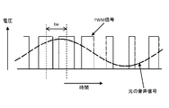
- FIG. 3 is a waveform diagram showing the relationship between the audio signal and the PWM signal.
- the microcomputer 10 ⁇ / b> C includes a CPU 11, a memory 12, and a timer 13.
- the memory 12 stores a driver 12B.
- the memory 12 also stores compressed audio data (audio compressed data), middleware for reproducing the compressed audio data while decoding it (reproduction control middleware), and the like.
- the CPU 11 decodes the compressed audio data and converts it into a PCM format audio signal based on a reproduction control middleware (not shown).
- the PCM format audio signal is a signal corresponding to the “original audio signal” of the analog waveform shown in FIG. 3. Note that the PCM format audio signal is discrete digital data having a predetermined sampling frequency.
- the CPU 11 controls the timer 13 built in the microcomputer 10C based on the driver 12B, thereby generating a PWM signal corresponding to the PCM format analog waveform audio signal.
- the PWM signal has a constant output pulse period tw.
- the time (width) of the pulse “H” (high level) and “L” (low level) differs depending on the magnitude of the input analog waveform audio signal.
- the timer 13 converts it into a PWM signal having a pulse width corresponding to the magnitude of the signal level of the PCM format audio signal according to the control of the driver 12B.
- a PWM signal having the same width of “H” and “L” of the pulse is generated.
- the width of “H” of the pulse is larger than the width of “L”, and the width of “H” becomes larger as the signal level is larger.
- a PWM signal is generated.
- the width of “L” of the pulse is larger than the width of “H”, and the width of “L” becomes larger as the signal level is larger.
- a PWM signal is generated.
- the timer 13 generates a PWM signal (digital pulse) having a pulse width proportional to the size of the PCM audio signal.
- the microcomputer 10C outputs the two PWM signals generated by the timer 13 from the two output pins to the H bridge circuit 20C.
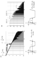
- FIG. 4 is a diagram showing frequency components of the PWM signal.
- 4A shows the frequency component of the PWM signal when the duty ratio is 50%
- FIG. 4B shows the frequency component of the PWM signal when the duty ratio is other than 50%.
- the duty ratio refers to a ratio at which the signal level is “H” in one cycle.
- harmonics One of the sources of noise generated by digital circuits is harmonics.
- the harmonics included in the PWM signal will be described.
- all waves having a fixed repetition period can be decomposed into a fundamental wave having a repetition frequency and a harmonic having a frequency that is an integral multiple of the fundamental wave.
- the multiple of the fundamental wave is called the harmonic order. Since the PWM signal has many repeated waveforms, when the frequency distribution (referred to as spectrum) is observed, it is decomposed into harmonics and looks like a discrete spectrum.
- T represents the pulse period
- tr represents the pulse rise time.
- the harmonics included in the PWM signal are not attenuated at a frequency of 1 / ⁇ or less, and ⁇ 20 dB / dec at frequencies from 1 / ⁇ to 1 / ⁇ r.
- ⁇ represents the pulse width
- ⁇ r represents the rise time of the pulse.
- FIG. 5 is a circuit diagram showing the configuration of the H-bridge circuit 20C shown in FIG. As shown in FIG. 5, the H-bridge circuit 20C includes four bipolar transistors Tr1 to Tr4. Hereinafter, the bipolar transistors Tr1 to Tr4 are simply referred to as transistors Tr1 to Tr4.
- Transistors Tr1 and Tr3 are PNP transistors, and transistors Tr2 and Tr4 are NPN transistors.
- the PNP transistors are turned on when a voltage lower than the power supply voltage Vcc is applied to the base.
- the NPN transistors are turned on when a high voltage with respect to the ground is applied to the base.
- the emitter terminal of the transistor Tr1 is connected to a power source having a voltage Vcc (for example, a voltage value of 15 V).
- the collector terminal of the transistor Tr1 is connected to the collector terminal of the transistor Tr2.
- a resistor R1 (for example, a resistance value of 33 k ⁇ ) is connected between the base terminal of the transistor Tr1 and the power supply.
- a Schottky barrier diode SBD1 is connected in parallel with the resistor R1 between the base terminal of the transistor Tr1 and the power supply.
- a capacitor C1 (for example, a capacitance of 0.1 ⁇ F) is connected between the base terminal of the transistor Tr1 and the base terminal of the transistor Tr2.
- the base terminal of the transistor Tr2 is connected to a signal input terminal for inputting a PWM signal (PWM ⁇ ), and the emitter terminal of the transistor Tr2 is connected to the ground.
- the configuration of the circuit including the transistors Tr3 and Tr4, the resistor R2, the Schottky barrier diode SBD2, and the capacitor C2 is the same as the configuration of the circuit including the transistors Tr1 and Tr2, the resistor R1, the Schottky barrier diode SBD1, and the capacitor C1. . That is, the emitter terminal of the transistor Tr3 is connected to the power supply of the voltage Vcc. The collector terminal of the transistor Tr3 is connected to the collector terminal of the transistor Tr4. A resistor R2 (for example, a resistance value of 33 k ⁇ ) is connected between the base terminal of the transistor Tr3 and the power supply.
- a Schottky barrier diode SBD2 is connected in parallel with the resistor R2 between the base terminal of the transistor Tr3 and the power supply.
- a capacitor C2 (for example, a capacitance of 0.1 ⁇ F) is connected between the base terminal of the transistor Tr3 and the base terminal of the transistor Tr4.
- the base terminal of the transistor Tr4 is connected to a signal input terminal for inputting a PWM signal (PWM ⁇ ), and the emitter terminal of the transistor Tr4 is connected to the ground.
- a piezoelectric element PZ and a resistor R0 are connected in series between a connection point between the collector terminal of the transistor Tr1 and the collector terminal of the transistor Tr2 and a connection point between the collector terminal of the transistor Tr3 and the collector terminal of the transistor Tr4. .
- the electrical characteristic of the piezoelectric element PZ is a capacitor (capacitor) (that is, the piezoelectric element PZ is equivalent to a capacitor). Therefore, the piezoelectric element PZ and the resistor R0 constitute a primary low-pass filter.
- the capacitance as a capacitor in the piezoelectric element PZ is, for example, 50 nF, and the resistance value of the resistor R0 is, for example, 1 k ⁇ .
- the piezoelectric buzzer 60 is composed of the piezoelectric element PZ and the resistor R0.
- the values (resistance value, capacitance value) of each element constituting the H-bridge circuit 20C and the values (resistance value, capacitance value) of each element (piezoelectric element PZ, resistance R0) constituting the piezoelectric buzzer 60 are examples.
- the value is not limited to the above value, and is appropriately set according to the characteristics of the piezoelectric element PZ.
- a voltage lower than the voltage Vcc is applied to the base terminals of the transistors Tr1 and Tr2 by the resistor R1. That is, the potential of the base terminal of the transistor Tr1 is lower than the potential of the emitter terminal of the transistor Tr1. In addition, the potential of the base terminal of the transistor Tr2 is higher than the potential (0 V) of the collector terminal of the transistor Tr2.
- the H bridge circuit 20C can reverse the current direction of the load by alternately turning on the two transistors on the diagonal line among the four transistors (switches), and the voltage of the battery Can make the most of it.
- the voltage of a small button-type battery is about 1V to 3V.
- the H-bridge circuit 20C is driven using a button type battery, the voltage of the button type battery is boosted to the power supply voltage by the charge pump.
- the sound reproducing device of the present invention can be mounted on a small device such as a health care product (for example, a thermometer or a blood glucose meter).
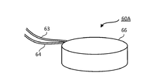
- FIG. 6 is a diagram showing the configuration of the piezoelectric buzzer 60 of the present invention.
- the piezoelectric element (piezoelectric vibration plate) shown in FIG. 6 has a structure in which a thin disk-shaped piezoelectric body (piezoelectric ceramics) 61 and a thin disk-shaped metal plate 62 such as brass or nickel are bonded (bonded). It is. Such a piezoelectric element structure is called a unimorph structure. Electrodes are formed on the surface of the piezoelectric body 61, and leads (cables) 63 are connected to the electrodes. An electrode is also formed on the surface of the metal plate 62, and a lead (cable) 64 is connected to the electrode. A resistor 65 is connected in the middle of the lead 64.
- the piezoelectric body 61 and the metal plate 62 correspond to the piezoelectric element PZ shown in FIG. 5, and the resistor 65 corresponds to the resistor R0 shown in FIG.
- the resistor 65 may be connected not in the middle of the lead 64 but in the middle of the lead 63.
- the piezoelectric body 61 When a voltage is applied to the piezoelectric element, the piezoelectric body 61 expands, but the metal plate 62 bonded to the piezoelectric body 61 bends in a predetermined direction without expanding and contracting. Further, when a voltage in the reverse direction is applied to the piezoelectric element, the piezoelectric body 61 contracts, but the metal plate 62 bonded to the piezoelectric body 61 does not expand and contract and bends in a direction opposite to the predetermined direction. When a signal voltage whose voltage direction changes alternately is applied to the piezoelectric element, vibrations in both directions are generated and sound waves are generated.
- an element composed of a piezoelectric body (piezoelectric ceramics) and a metal plate is referred to as a piezoelectric element, and a structure including a piezoelectric element and a resistor is referred to as a piezoelectric buzzer.
- a piezoelectric body piezoelectric ceramic
- an element constituted by a piezoelectric body and a metal plate may be referred to as a piezoelectric buzzer.
- the piezoelectric buzzer is called a piezoelectric speaker (piezo speaker), a piezoelectric sounder, and the like, and is not clearly distinguished.
- the piezoelectric buzzer in the present embodiment includes the piezoelectric speaker (piezo speaker), the piezoelectric sounder, and the like. It is a configuration.
- the characteristics of the piezoelectric element vary depending on the material, diameter, and thickness of the piezoelectric body and the material, diameter, and thickness of the metal plate. For example, the resonance point (resonance frequency), the resonance resistance, and the capacitance are changed by the piezoelectric element.
- the present invention is intended to achieve high-quality sound output using an inexpensive piezoelectric buzzer. Therefore, in this embodiment, a piezoelectric element used as an electronic buzzer is used. Assumed.
- FIG. 7 is a perspective view showing a configuration of a piezoelectric buzzer 60A in which a piezoelectric element and a resistor are housed in a package 66.
- a piezoelectric element composed of a piezoelectric body 61 and a metal plate 62 and a resistor 65 connected to the piezoelectric element are housed in a package 66.
- the piezoelectric element and the resistor 65 are configured as one component.
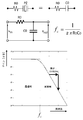
- FIG. 8 is a circuit diagram of the primary low-pass filter and a graph showing the frequency characteristics of the primary low-pass filter.
- the piezoelectric element PZ is regarded as the capacitor C0 as an electrical characteristic.
- the RC circuit including the resistor R0 and the capacitor C0 functions as a primary low-pass filter (RC filter).
- the first-order low-pass filter formed of the RC circuit passes a signal having a frequency equal to or lower than the break frequency fc of the RC circuit, and a signal having a frequency equal to or higher than the break frequency fc of the RC circuit is ⁇ 20 dB. Attenuate at / dec.
- the break frequency fc of the RC circuit constituted by the piezoelectric element PZ and the resistor R0 is set to be equal to or lower than the resonance point (resonance frequency) of the piezoelectric element PZ. According to such a configuration, a frequency component higher than the resonance point of the piezoelectric element PZ can be suppressed by the RC filter, and it becomes possible to output a human voice or music with high sound quality.
- 1/2 of the break frequency of the RC circuit constituted by the piezoelectric element PZ and the resistor R0 may be equal to or lower than the resonance point of the piezoelectric element PZ. According to such a configuration, higher frequency components can be suppressed by the RC filter, and it becomes possible to further output a human voice or music with high sound quality.
- the resistor R0 (resistor 65 in FIG. 6) connected in series with the piezoelectric element PZ has the following four roles. 1. As described above, there is a role of forming an RC filter (primary low-pass filter) together with a capacitor equivalent to a piezoelectric element. 2. It plays a role of lowering the Q of mechanical vibration resonance existing in the piezoelectric buzzer 60. In general, since a piezoelectric buzzer is used as an electronic buzzer, it is intentionally designed so that mechanical vibration with a high Q is likely to occur. In the present embodiment, the pass band of the primary low-pass filter can be set by adjusting the resistance value of the resistor R0 in accordance with the characteristics of the piezoelectric element PZ.
- the resistor R0 is connected in series to the piezoelectric element PZ, and the capacitor C0 equivalent to the piezoelectric element PZ and the resistor R0 form a low-pass filter.
- the piezoelectric buzzer and sound reproducing device of the present invention can be used as a device that outputs a guide sound.
- a guide sound For example, in-car / premises announcements such as railways and buses, signals, building entry / exit management terminals, surveillance cameras, medical equipment, AED (Automated External Defibrillator), industrial printers, composite printers for offices, It can be used for sound effects of consumer inkjet printers and amusement machines.
- the piezoelectric buzzer and the sound reproducing device of the present invention can be used as a device for outputting sound under severe temperature / environment conditions. For example, it can be used for fire / gas / evacuation alarms, construction machines, automobiles, vending machines, ATMs, and the like.
- a resistor is connected to one of the two terminals of the piezoelectric element PZ, but a resistor may be connected to both of the two terminals. Even in such a case, it can function as an RC filter.
- the element of the unimorph structure was used for the piezoelectric element, you may use the element of a bimorph structure and a laminated
- the H bridge circuit is composed of four bipolar transistors, it may be composed of four FETs (H bridge circuit 20B in FIG. 1B).
Landscapes
- Physics & Mathematics (AREA)
- Engineering & Computer Science (AREA)
- Acoustics & Sound (AREA)
- Signal Processing (AREA)
- Multimedia (AREA)
- Circuit For Audible Band Transducer (AREA)
- Piezo-Electric Transducers For Audible Bands (AREA)
- Amplifiers (AREA)
Abstract
Le problème décrit par la présente invention est de fournir : un vibreur piézoélectrique qui est peu coûteux, possède un son de haute qualité, et présente une faible consommation de courant ; et un dispositif de reproduction audio qui reproduit audio à l'aide dudit vibreur piézoélectrique. À cet effet, la présente invention concerne : un vibreur piézoélectrique (60) ayant un élément piézoélectrique (PZ) qui délivre en sortie, sous la forme d'audio, des vibrations générées à partir d'un corps piézoélectrique (61) suite à l'application d'une tension de signal au corps piézoélectrique (61), et comportant une résistance (R0) qui est reliée en série à l'élément piézoélectrique (PZ) et qui constitue un filtre passe-bas conjointement avec un condensateur équivalent à l'élément piézoélectrique (PZ) ; un micro-ordinateur (20) qui génère un signal PWM correspondant à un signal audio ; et un circuit d'attaque (20C) dans lequel l'amplification de puissance est effectuée par une opération de commutation effectuée, sur la base du signal PWM, par quatre transistors bipolaires constituant un circuit à pont en H (20C) et qui délivre en sortie une tension de signal de faible courant de consommation correspondant au signal PWM au vibreur piézoélectrique (60), dans laquelle l'élément piézoélectrique (61) et la résistance (65) comportant une valeur de résistance appropriée pour la caractéristique de l'élément piézoélectrique (61) sont reliés en série, de manière à générer une sortie audio du vibreur piézoélectrique (60).
Applications Claiming Priority (2)
| Application Number | Priority Date | Filing Date | Title |
|---|---|---|---|
| JP2016-255204 | 2016-12-28 | ||
| JP2016255204A JP6308696B1 (ja) | 2016-12-28 | 2016-12-28 | 音声再生装置 |
Publications (1)
| Publication Number | Publication Date |
|---|---|
| WO2018123730A1 true WO2018123730A1 (fr) | 2018-07-05 |
Family
ID=61901947
Family Applications (1)
| Application Number | Title | Priority Date | Filing Date |
|---|---|---|---|
| PCT/JP2017/045521 Ceased WO2018123730A1 (fr) | 2016-12-28 | 2017-12-19 | Dispositif de reproduction audio |
Country Status (2)
| Country | Link |
|---|---|
| JP (1) | JP6308696B1 (fr) |
| WO (1) | WO2018123730A1 (fr) |
Cited By (1)
| Publication number | Priority date | Publication date | Assignee | Title |
|---|---|---|---|---|
| US11647331B2 (en) | 2019-10-29 | 2023-05-09 | Seiko Epson Corporation | Circuit device, sound reproduction device, and electronic apparatus |
Families Citing this family (4)
| Publication number | Priority date | Publication date | Assignee | Title |
|---|---|---|---|---|
| CN109407579B (zh) * | 2018-10-16 | 2021-06-01 | 浩云科技股份有限公司 | 一种独立声波算法控制电路 |
| JP7427529B2 (ja) * | 2020-05-29 | 2024-02-05 | キヤノン株式会社 | ブザー制御装置、fax通信装置、およびブザー制御方法 |
| JP2024003981A (ja) * | 2022-06-28 | 2024-01-16 | 株式会社Cri・ミドルウェア | 音声再生圧電ブザー |
| WO2025187197A1 (fr) * | 2024-03-07 | 2025-09-12 | ソニーセミコンダクタソリューションズ株式会社 | Dispositif acoustique |
Citations (7)
| Publication number | Priority date | Publication date | Assignee | Title |
|---|---|---|---|---|
| JPS59146296A (ja) * | 1983-02-08 | 1984-08-22 | Murata Mfg Co Ltd | 圧電スピ−カの駆動方法 |
| JPS6021694A (ja) * | 1983-07-18 | 1985-02-04 | Nippon Telegr & Teleph Corp <Ntt> | 圧電形受話器 |
| JPH06186980A (ja) * | 1992-12-15 | 1994-07-08 | New Japan Radio Co Ltd | 発音体駆動回路 |
| JPH077788A (ja) * | 1993-03-19 | 1995-01-10 | Ford Motor Co | 音響再生システム及び音響再生方法 |
| JP2006094158A (ja) * | 2004-09-24 | 2006-04-06 | Nec Access Technica Ltd | 駆動回路および該駆動回路を備える携帯機器 |
| JP2007033939A (ja) * | 2005-07-27 | 2007-02-08 | Denso Corp | 圧電ブザー駆動回路 |
| WO2007132839A1 (fr) * | 2006-05-15 | 2007-11-22 | Asahi Kasei Emd Corporation | Dispositif de commande, procédé de commande et dispositif d'information |
-
2016
- 2016-12-28 JP JP2016255204A patent/JP6308696B1/ja active Active
-
2017
- 2017-12-19 WO PCT/JP2017/045521 patent/WO2018123730A1/fr not_active Ceased
Patent Citations (7)
| Publication number | Priority date | Publication date | Assignee | Title |
|---|---|---|---|---|
| JPS59146296A (ja) * | 1983-02-08 | 1984-08-22 | Murata Mfg Co Ltd | 圧電スピ−カの駆動方法 |
| JPS6021694A (ja) * | 1983-07-18 | 1985-02-04 | Nippon Telegr & Teleph Corp <Ntt> | 圧電形受話器 |
| JPH06186980A (ja) * | 1992-12-15 | 1994-07-08 | New Japan Radio Co Ltd | 発音体駆動回路 |
| JPH077788A (ja) * | 1993-03-19 | 1995-01-10 | Ford Motor Co | 音響再生システム及び音響再生方法 |
| JP2006094158A (ja) * | 2004-09-24 | 2006-04-06 | Nec Access Technica Ltd | 駆動回路および該駆動回路を備える携帯機器 |
| JP2007033939A (ja) * | 2005-07-27 | 2007-02-08 | Denso Corp | 圧電ブザー駆動回路 |
| WO2007132839A1 (fr) * | 2006-05-15 | 2007-11-22 | Asahi Kasei Emd Corporation | Dispositif de commande, procédé de commande et dispositif d'information |
Cited By (1)
| Publication number | Priority date | Publication date | Assignee | Title |
|---|---|---|---|---|
| US11647331B2 (en) | 2019-10-29 | 2023-05-09 | Seiko Epson Corporation | Circuit device, sound reproduction device, and electronic apparatus |
Also Published As
| Publication number | Publication date |
|---|---|
| JP2018107752A (ja) | 2018-07-05 |
| JP6308696B1 (ja) | 2018-04-11 |
Similar Documents
| Publication | Publication Date | Title |
|---|---|---|
| JP6308705B1 (ja) | 音声再生装置 | |
| JP6308696B1 (ja) | 音声再生装置 | |
| US7461281B2 (en) | Capacitive load driving circuit, electrostatic transducer, method of setting circuit constant, ultrasonic speaker, display device, and directional acoustic system | |
| CN101282591B (zh) | 蜂鸣器驱动电路 | |
| US20030228021A1 (en) | Acoustic-signal emitting device for vehicles | |
| CN202586876U (zh) | 差频消除电路、脉冲宽度调制信号产生电路与放大器电路 | |
| EP1509337B1 (fr) | Circuit de commande electronique et dispositif emetteur de signaux acoustiques pour vehicules | |
| JP4426738B2 (ja) | 圧電スピーカシステム | |
| JPS62161199A (ja) | 震音発生装置 | |
| JP6474523B1 (ja) | 音声再生装置におけるノイズを消す方法 | |
| US11539335B2 (en) | Transducer driver circuitry | |
| WO2019131639A1 (fr) | Dispositif acoustique, dispositif de commande acoustique et programme | |
| US7629842B2 (en) | Class D audio amplifier | |
| US7171011B2 (en) | Acoustic drive circuit | |
| JP6186135B2 (ja) | D級アンプおよび電子機器 | |
| CN210202074U (zh) | 模拟蜂鸣器电路和电子设备 | |
| JP2016063299A (ja) | オーディオアンプ、電子機器、オーディオ信号の再生方法 | |
| JPH0453320B2 (fr) | ||
| JP2025158587A (ja) | 半導体装置及び電子機器 | |
| KR101739087B1 (ko) | 하이파이를 제공하는 오디오 신호 증폭 회로 및 방법 | |
| WO2002095935A1 (fr) | Amplificateur de sortie audio | |
| CN121768344A (zh) | 蜂鸣器装置、蜂鸣器的驱动系统及其方法 | |
| JPS63156405A (ja) | 圧電信号発信装置 | |
| GB2388994A (en) | Piezoelectric sounder and drive circuit arranged to reproduce an alarm tone and a voice message | |
| JP2021136563A (ja) | 駆動システム、音再生装置及び電子機器 |
Legal Events
| Date | Code | Title | Description |
|---|---|---|---|
| 121 | Ep: the epo has been informed by wipo that ep was designated in this application |
Ref document number: 17886817 Country of ref document: EP Kind code of ref document: A1 |
|
| NENP | Non-entry into the national phase |
Ref country code: DE |
|
| 122 | Ep: pct application non-entry in european phase |
Ref document number: 17886817 Country of ref document: EP Kind code of ref document: A1 |