WO2018123782A1 - Relais électromagnétique - Google Patents
Relais électromagnétique Download PDFInfo
- Publication number
- WO2018123782A1 WO2018123782A1 PCT/JP2017/045843 JP2017045843W WO2018123782A1 WO 2018123782 A1 WO2018123782 A1 WO 2018123782A1 JP 2017045843 W JP2017045843 W JP 2017045843W WO 2018123782 A1 WO2018123782 A1 WO 2018123782A1
- Authority
- WO
- WIPO (PCT)
- Prior art keywords
- coil
- terminal
- movable contact
- wire
- coil wire
- Prior art date
- Legal status (The legal status is an assumption and is not a legal conclusion. Google has not performed a legal analysis and makes no representation as to the accuracy of the status listed.)
- Ceased
Links
Images


Classifications
-
- H—ELECTRICITY
- H01—ELECTRIC ELEMENTS
- H01H—ELECTRIC SWITCHES; RELAYS; SELECTORS; EMERGENCY PROTECTIVE DEVICES
- H01H50/00—Details of electromagnetic relays
- H01H50/14—Terminal arrangements
-
- H—ELECTRICITY
- H01—ELECTRIC ELEMENTS
- H01H—ELECTRIC SWITCHES; RELAYS; SELECTORS; EMERGENCY PROTECTIVE DEVICES
- H01H50/00—Details of electromagnetic relays
- H01H50/44—Magnetic coils or windings
Definitions
- the present invention relates to an electromagnetic relay. This application claims priority based on Japanese Patent Application No. 2016-256370 filed in Japan on December 28, 2016, the contents of which are incorporated herein by reference.
- a contact portion and a coil wire material that excites and demagnetizes an iron core are provided adjacent to each other on a base portion.
- the contact portion includes a movable contact connected to the movable contact terminal and a fixed contact connected to the fixed contact terminal. The movable contact abuts and separates from the fixed contact based on the demagnetization and excitation of the coil wire.
- the movable contact is provided on one end side of a leaf spring-like movable contact spring, and the other end side of the movable contact spring is supported by a yoke that forms a magnetic path together with the iron core.
- the base end of the movable contact terminal is also attached to the yoke.
- the movable contact and the movable contact terminal are connected via the movable contact spring and the yoke.
- the movable contact and the fixed contact are provided in a state of being separated from each other.
- the coil wire is connected to the movable contact terminal, and the coil is energized through the movable contact terminal.
- the movable contact When the coil wire is energized, the movable contact is attracted and brought into contact with the fixed contact by the electromagnetic force generated in the coil wire, and both are electrically connected to energize the fixed contact terminal and the movable contact terminal.
- the movable contact When the energization to the coil wire is interrupted, the movable contact is separated from the fixed contact by the elastic action of the movable contact spring provided with the movable contact, and the energization of the fixed contact terminal and the movable contact terminal is interrupted.
- connection piece for locking the terminal portion of the coil wire material is often provided on the movable contact terminal.
- the connection space between the terminal portion of the coil wire and the connection piece is very narrow due to the restriction of the size of the electromagnetic relay, and the connection work between the terminal portion of the coil wire and the connection piece is troublesome. For this reason, various techniques for simplifying the connection work between the terminal portion of the coil wire and the connection piece have been proposed.
- a technique is proposed in which the movable contact terminal is provided so as to be rotatable with respect to the base portion, and the movable contact terminal is turned 90 ° from a predetermined position when the coil wire terminal portion and the connection piece are connected.
- the movable contact terminal is rotated, a wide connection space between the terminal portion of the coil wire and the connection piece can be secured. That is, the end portion of the coil wire rod is pulled out in a predetermined direction, and then the end portion of the coil wire rod is drawn in a direction orthogonal to the predetermined direction so as to lock the end portion of the coil wire rod to the connection piece. Then, after the terminal portion of the coil wire rod is locked to the connection piece, the movable contact terminal is returned to a predetermined position. Thereby, simplification of the connection work of a coil wire is aimed at.
- the terminal portion of the coil wire is drawn out in a predetermined direction, and thereafter, the terminal portion of the coil wire is drawn in a direction to be engaged with the connecting piece. Become a direction. For this reason, it is difficult to say that the connection work between the terminal portion of the coil wire and the connection piece can be simplified. Moreover, it is necessary to set the terminal part of a coil wire to be long because the drawing direction is two directions.
- the present invention provides an electromagnetic relay capable of effectively simplifying the connecting operation of the terminal portion of the coil wire and reducing the cost of the coil wire.
- an electromagnetic relay includes a coil bobbin, a coil made of a coil wire wound around the coil bobbin, and the coil wire through the coil bobbin.
- a wound iron core, a yoke that supports the iron core and forms a magnetic path with the iron core, a fixed contact terminal provided with a fixed contact, and an electric connection to the yoke and the fixing A movable contact provided so as to be able to contact with and separate from the contact; a movable contact terminal having one end attached to the yoke; a coil terminal for supplying a current to the coil wire; and a coil terminal provided to the coil terminal.
- the terminal portion and the terminal connection portion can be connected by simply pulling out the terminal portion of the coil wire material in one direction without rotating the movable contact terminal as in the prior art. For this reason, the connection operation
- work of the terminal part of a coil wire can be simplified effectively, and the cost of a coil wire can also be reduced.
- the coil bobbin is externally fitted to the iron core and the cylindrical bobbin body around which the coil wire is wound, Two outer flange portions that are provided at both axial ends of the bobbin main body and prevent the coil wire rod from being collapsed, and one of the two outer flange portions is formed between the coil wire rod and the terminal connection portion.
- a lead-out groove that is interposed therebetween and guides the terminal portion of the coil wire to the terminal connection portion side, and the lead-out groove is disposed at a position at least partially overlapping the terminal connection portion when viewed from the axial direction. ing.
- the terminal connecting portion is arranged radially inward of the outer flange portion of the coil bobbin, and the direction in which the terminal portion of the coil wire is routed can be unidirectional. For this reason, an electromagnetic relay can be reduced in size, simplifying the connection operation of the terminal part of a coil wire. Moreover, since the lead-out groove functions as a guide for guiding the terminal portion of the coil wire to the terminal connecting portion side, the connection work of the terminal portion of the coil wire can be facilitated.
- the movable contact terminal connects an element that absorbs the counter electromotive voltage of the coil.
- An element connecting portion is provided, and at least a part of the element connecting portion is disposed at a position overlapping the terminal connecting portion when viewed from the axial direction.
- the side view of the electromagnetic relay in embodiment of this invention The front view of the electromagnetic relay in embodiment of this invention.
- the top view which looked at the electromagnetic relay in embodiment of this invention from each terminal side shows the state which permeate
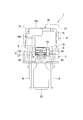
- FIG. 1 is a side view of the electromagnetic relay 1.
- FIG. 2 is a front view of the electromagnetic relay 1.
- the electromagnetic relay 1 is used, for example, to turn on / off a lamp (Lamp) mounted on a vehicle.
- the electromagnetic relay 1 includes a base part 2, a coil 4 provided on the one surface 2 a side of the base part 2, and a contact provided between the base part 2 and the coil 4.
- a rectangular box-shaped cover 17 for covering.
- the resistor 16 absorbs the counter electromotive voltage of the coil 4.
- the register 16 includes a register main body 61 and a pair of lead wires 62 extending from the register main body 61.
- the protruding direction of each terminal 8, 10, 12 may be referred to as the lower side, and the opposite side of the protruding direction of these terminals 8, 10, 12 may be referred to as the upper side.
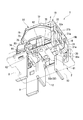
- FIG. 3 is a perspective view of the base portion 2 as viewed from the coil 4 side.
- the base portion 2 is formed in a substantially rectangular flat plate shape with an insulating resin.
- On one end side in the longitudinal direction of the base portion 2 (the left side in FIGS. 1 and 3 and the front side in FIG. 2), there are long coil terminal slits 7 along the longitudinal direction of the base portion 2 on both sides in the short direction. Is formed.
- the coil terminals 8 are inserted or press-fitted into the coil terminal slits 7, respectively.
- the base portion 2 has a movable contact terminal slit 9 that is long along the short side direction of the base portion 2 on the other end side in the longitudinal direction (right side in FIG. 1).
- the movable contact terminal 10 is inserted or press-fitted into the movable contact terminal slit 9.
- a long fixed contact terminal slit 11 is formed along the short direction of the base portion 2 at the approximate center in the longitudinal direction of the base portion 2.
- the fixed contact terminal 12 is inserted or press-fitted into the fixed contact terminal slit 11.
- a register housing recess 40 for housing the register 16 is formed between the movable contact terminal slit 9 and the fixed contact terminal slit 11 on the one surface 2 a side of the base portion 2.
- the register storage recess 40 is formed along the length of the main body storage recess 41 along the short direction of the base portion 2 and at both longitudinal ends of the main body storage recess 41 (both sides of the base portion 2 in the short direction of the base portion 2).
- Each of the lead wire storage recesses 42 is formed in communication with the main body storage recess 41.
- the lead wire storage recess 42 is bent from the opposite end of the short side portion 42a to the main body storage recess 41, and the short side portion 42a extending from both longitudinal ends of the main body storage recess 41 to the front of both ends of the base portion 2 in the short direction.
- a longitudinal portion 42c that is bent and extended along the longitudinal direction of the base portion 2 via the portion 42b is formed in communication.
- the long portion 42c extends from the end of the short portion 42a until it communicates with the coil terminal slit 7.
- the register body 61 of the register 16 is housed in the body housing recess 41 of the register housing recess 40 configured as described above. Further, the lead wire 62 of the register 16 is bent along the lead wire storage recess 42 and stored in the lead wire storage recess 42. That is, in the register 16, the register main body 61 is disposed between the fixed contact terminal slit 11 (fixed contact terminal 12) and the movable contact terminal slit 9 (movable contact terminal 10). Then, the lead wire 62 extends from the register main body 61 to the coil terminal slit 7 (coil terminal 8) so as to bypass (straddle) the fixed contact terminal slit 11 (fixed contact terminal 12). Yes.
- first support column 5 is provided on one end side in the longitudinal direction of the base portion 2 so as to project toward the side opposite to the projecting direction of the terminals 8, 10, 12 (upper side). Further, on the other end in the longitudinal direction of the base portion 2, second support columns 6 are provided on both sides in the short direction of the base portion 2 so as to protrude in the opposite direction to the protruding direction of the terminals 8, 10, 12. ing.
- the first support column 5 and the second support column 6 support a yoke 19 having a substantially L-shaped cross section.
- a magnetic path is formed in the yoke 19.
- the yoke 19 is formed by bending a metal plate. That is, the yoke 19 has an upper wall 19a facing the base portion 2 at a predetermined interval, and a vertical wall 19b that bends and extends substantially perpendicularly to the upper wall 19a from the end of the upper wall 19a on the second support column 6 side. And have. Furthermore, the yoke 19 is formed so that the direction in which the upper wall 19a and the vertical wall 19b are continuous becomes longer.
- the cross-sectional shape along the surface direction of the base part 2 is formed in the substantially C shape.
- an engagement piece 19c that can be inserted into the first support column 5 is bent and extended on the upper wall 19a of the yoke 19 at the end of the first support column 5 side. Thereby, one end of the yoke 19 is supported by the first support column 5.
- the two second struts 6 are respectively disposed at both ends of the base portion 2 in the short direction.
- the two second struts 6 also have a substantially C-shaped cross section along the surface direction, and the opening directions thereof are opposed to each other.
- pillar 6 is supporting so that the vertical wall 19b of the yoke 19 may be clamped from the transversal direction both sides.
- an iron core 18 formed in a rod shape with a magnetic material is fixed to the upper wall 19a of the yoke 19 at the center.
- the iron core 18 is suspended from the upper wall 19 a of the yoke 19 toward the base portion 2.
- the coil 4 is fitted and fixed to such an iron core 18. Further, a flange portion 18a is formed at the tip of the iron core 18, and the coil 4 is prevented from coming off from the iron core 18.
- FIG. 4 is a perspective view of the electromagnetic relay 1 as viewed from the terminals 8, 9, 10 (coil terminal 8, movable contact terminal 10, fixed contact terminal 12) side, and shows a state in which the base portion 2 and the cover 17 are removed.
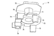
- FIG. 5 is a perspective view of the coil bobbin 14. As shown in FIGS. 1, 4, and 5, the coil 4 includes a coil bobbin 14 that is externally fitted and fixed to an iron core 18, and a coil wire 15 that is wound around the coil bobbin 14.
- the coil bobbin 14 is formed of an insulating material such as resin.
- the coil bobbin 14 includes a cylindrical bobbin main body 71 and two outer flange portions 72 and 73 (an upper outer flange portion 72 and a lower outer flange portion 72 provided on both ends in the axial direction of the bobbin main body 71 and projecting radially outward. And an outer flange portion 73).
- the bobbin main body 71 is externally fixed to the iron core 18.
- a coil wire 15 is wound around the outer peripheral surface of the bobbin main body 71.
- the two outer flange portions 72 and 73 have a role of preventing the coil wire 15 from being collapsed.
- the lower outer flange portion 73 disposed on the base portion 2 side has coil terminal support at positions corresponding to the coil terminal slits 7 formed in the base portion 2.
- the part 74 is integrally formed.
- the coil terminal support portion 74 is formed in a substantially rectangular tube shape, and is formed to protrude toward the base portion 2 side so that the proximal end of the coil terminal 8 can be press-fitted.
- a restriction portion 75 is integrally formed at a position corresponding to the longitudinal portion 42c of the lead wire housing recess 42 formed in the base portion 2.
- the restricting portion 75 is formed in a substantially quadrangular prism shape and protrudes toward the base portion 2.
- the restricting portion 75 is formed in a substantially rectangular shape so that a cross section along the surface direction of the base portion 2 becomes longer along the longitudinal portion 42 c of the lead wire accommodating recess 42. Further, the restricting portion 75 is disposed closer to the bent portion 42b in the longitudinal portion 42c. Further, the protruding length of the restricting portion 75 is set to a length that faces the inside of the longitudinal portion 42 c of the lead wire housing recess 42.
- the restriction portion 75 configured as described above prevents the register 16 housed in the lead wire housing recess 42 from being lifted from the base portion 2.
- the restricting unit 75 restricts the displacement of the register 16 toward the coil 4. More specifically, when the leading end of the restricting portion 75 is exposed in the longitudinal portion 42 c of the lead wire storing recess 42, the tip contacts the lead wire 62 of the register 16 stored in the lead wire storing recess 42. For this reason, the restricting portion 75 restricts the displacement of the register 16 toward the coil 4 side.
- the leading end of the restricting portion 75 is exposed in the longitudinal portion 42 c of the lead wire housing recess 42, so that the lead wire 62 of the register 16 is sandwiched between the tip and the bottom surface of the lead wire housing recess 42. .
- the register 16 is securely fixed in the register housing recess 40.
- a lead-out groove 76 is formed in the vicinity of the coil terminal support portion 74 of the lower outer flange portion 73.
- the lead-out groove 76 is formed from the outer peripheral edge of the lower outer flange portion 73 to the region around which the coil wire 15 is wound. That is, the lead-out groove 76 is formed so that a part thereof overlaps with the winding region of the coil wire 15 as viewed from the axial direction of the iron core 18 (coil bobbin 14).
- the lead-out groove 76 formed in this way leads the terminal portion 15a (see FIG. 7) of the coil wire 15 wound around the coil bobbin 14 to the coil terminal 8 side (details will be described later).
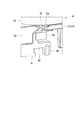
- FIG. 6 is a plan view of the electromagnetic relay 1 as viewed from the terminals 8, 9, 10 (coil terminal 8, movable contact terminal 10, fixed contact terminal 12) side, and shows a state where the base portion 2 is transmitted.
- the coil terminal 8 is formed in a substantially long plate shape.
- the coil terminal 8 is extended along the direction orthogonal to the surface direction of the base part 2, ie, the axial direction of the iron core 18 (coil bobbin 14).
- the coil terminal 8 is formed so that the cross-sectional shape along the surface direction of the base portion 2 is along the extending direction of the coil terminal slit 7 (longitudinal direction of the base portion 2).
- the coil terminal 8 is inserted through the coil terminal slit 7 of the base portion 2.
- a support piece 81 is integrally formed at the base end of the coil terminal 8.
- the support piece 81 is press-fitted into a coil terminal support portion 74 that is integrally formed with the coil bobbin 14.
- a connection piece 82 extending toward the fixed contact terminal 12 is integrally formed at the base end of the coil terminal 8. The connection piece 82 extends to the vicinity of the fixed contact terminal 12.
- FIG. 7 is an enlarged perspective view of the connection piece 82.
- a coil hook 83 that protrudes toward the coil 4 side is integrally formed at the base of the connection piece 82 so as to avoid the coil terminal support portion 74 of the coil bobbin 14. Yes.
- the coil hook 83 is located directly below the lead-out groove 76 of the coil bobbin 14.
- the coil hook 83 is disposed at a position overlapping the lead-out groove 76 of the coil bobbin 14 when viewed from the axial direction of the iron core 18 (coil bobbin 14).
- the terminal portion 15a of the coil wire 15 led out via the lead-out groove 76 is locked to the coil hook 83, and is fixed by, for example, fusing. Thereby, the coil wire 15 and the coil terminal 8 are connected.
- a resistor connection portion 83 is bent and extended from the tip of the connection piece 82 toward the side opposite to the coil 4.
- the register connecting portion 83 is disposed at a position where a part thereof overlaps with the coil hook 83 when viewed from the axial direction of the iron core 18 (coil bobbin 14).
- the connection piece 82 is provided with the coil hook 83 and the resistor connection portion 83. For this reason, the coil hook 83 and the resistor connecting portion 83 are arranged close to each other.
- the coil terminal slit 7 formed in the base portion 2 is formed so that only the coil terminal 8 is inserted.
- the coil terminal slits 7 of the base portion 2 are formed so as to penetrate in the thickness direction of the base portion 2 only at locations corresponding to the coil terminals 8.
- the location corresponding to the connection piece 82 and the register connection part 84 of the slit 7 for coil terminals is made into the connection piece accommodation recessed part 7a recessedly provided so that the one surface 2a side might open.
- the connection piece storage recess 7 a communicates with the longitudinal portion 42 c of the register storage recess 40.
- connection piece housing recess 7 a is formed to be uneven so as to correspond to the unevenness of the connection piece 82 and the register connection portion 84.
- connection piece 82 of the coil terminal 8 and the register connection portion 84 are surely brought into contact with the bottom surface of the connection piece storage recess 7a, and the positioning of the coil terminal 8 (connection piece 82, coil hook 83 and register connection portion 84) is achieved.
- the lead wire 62 of the register 16 accommodated in the register accommodating recess 40 is extended to the register connecting portion 84 arranged in this way.
- the tip of the lead wire 62 is fixed to the register connection portion 84 by, for example, fusing.
- a movable contact spring 20 is attached to the vertical wall 19 b of the yoke 19.
- the movable contact spring 20 supports a movable contact 21 that constitutes one of the contact portions 3.
- the movable contact spring 20 is made of a conductive leaf spring material and has a substantially L-shaped cross section.
- the movable contact spring 20 is bent and extended so as to be interposed between the base portion 2 and the coil 4 from the mounting seat 31 attached to the vertical wall 19b of the yoke 19 and the base portion 2 side end of the mounting seat 31. And the operating piece 32.
- the mounting seat 31 is formed in a large portion at the center of the vertical wall 19b of the yoke 19 and is formed in a substantially C shape in plan view. That is, the mounting seat 31 extends in the longitudinal direction so as to straddle the pair of arm portions 31a facing each other in the short-side direction and the opposite ends of the base portions 2 of the arm portions 31a. It is comprised by the connection part 31b which connects the arm part 31a. Both ends of the connecting portion 31b that are connected to each arm portion 31a are fixed to the vertical wall 19b of the yoke 19 by caulking or welding, respectively.
- the operating piece 32 is bent and extended from the tip of each arm portion 31a, the main body 32b extending from the tip of the support piece 32a, and set to a plate width capable of connecting the support pieces 32a, It is comprised by. And the movable contact 21 is attached to the front-end
- the vertical wall 19b of the yoke 19 is provided with a mounting seat 33 provided at the base end of the movable contact terminal 10 and extending along the vertical wall 19b.
- the mounting seat 33 is disposed so as to avoid the two arm portions 31 a of the mounting seat 31 that constitutes the movable contact spring 20.
- tip of the attachment seat 33 is being fixed to the vertical wall 19b of the yoke 19 by caulking or welding, respectively.
- the fixing position of the mounting seat 33 of the movable contact terminal 10 and the fixing position of the mounting seat 31 of the movable contact spring 20 are arranged substantially on the same straight line.
- the movable contact terminal 10 is formed in a substantially long plate shape, and extends along the direction orthogonal to the surface direction of the base portion 2, that is, along the axial direction of the iron core 18 (coil bobbin 14).
- the movable contact terminal 10 is formed so that the cross-sectional shape along the surface direction of the base portion 2 is along the extending direction of the movable contact terminal slit 9 (short direction of the base portion 2).
- Such a movable contact terminal 10 is inserted into the movable contact terminal slit 9 of the base portion 2. And most of the movable contact terminal 10 protrudes from the base portion 2 toward the side opposite to the coil 4 except for the base end portion.
- the fixed contact terminal 12 inserted through the fixed contact terminal slit 11 of the base portion 2 also extends in a direction orthogonal to the surface direction of the base portion 2, that is, along the axial direction of the iron core 18 (coil bobbin 14). .
- the fixed contact terminal 12 is formed so that the cross-sectional shape along the surface direction of the base portion 2 is along the extending direction of the fixed contact terminal slit 11 (short direction of the base portion 2).
- Such a fixed contact terminal 12 is inserted into the fixed contact terminal slit 11 of the base portion 2. And most of the fixed contact terminal 12 protrudes from the base portion 2 toward the side opposite to the coil 4 except for the base end portion.
- an internal contact portion 36 that bends and extends toward the movable contact 21 is integrally formed.
- the tip of the internal contact portion 36 is interposed between the movable contact 21 and the coil 4.
- the fixed contact 22 is attached to the tip of the internal contact portion 36. Thereby, the movable contact 21 and the fixed contact 22 are arranged to face each other with a predetermined interval.
- the coil 4 is formed by winding the coil wire 15 around the bobbin body 71 of the coil bobbin 14.
- the end opposite to the flange portion 18 a of the iron core 18 is directed to the lower outer flange 73 side of the bobbin main body 71, and the iron core 18 is inserted into the bobbin main body 71 as it is.
- the end portion of the iron core 18 is fixed to the upper wall 19 a of the yoke 19 with the flange portion 18 a of the iron core 18 in contact with the lower outer flange portion 73 of the bobbin main body 71.
- the mounting seat 31 of the movable contact spring 20 and the mounting seat 33 of the movable contact terminal 10 are fixed to the vertical wall 19b of the yoke 19 by caulking or welding. Further, the support piece 81 of the fixed contact terminal 12 is directed to the coil terminal support portion 74 side of the coil bobbin 14, and the connection piece 82 of the fixed contact terminal 12 is directed to the movable contact terminal 10 side. Then, the support piece 81 is press-fitted into the coil terminal support portion 74 as it is.
- the terminal portion 15 a of the coil wire 15 is directed toward the coil hook 83 formed on the support piece 81 of the fixed contact terminal 12 through the lead-out groove 76 formed in the lower outer flange portion 73 of the coil bobbin 14. Is derived. And the terminal part 15a of the coil wire 15 is latched to the coil hook 83, and the coil hook 83 and the terminal part 15a of the coil wire 15 are fixed by, for example, fusing.
- the lead-out groove 76 is formed from the outer peripheral edge of the lower outer flange portion 73 to the region around which the coil wire 15 is wound. That is, the lead-out groove 76 is formed so that a part thereof overlaps with the winding region of the coil wire 15 as viewed from the axial direction of the iron core 18 (coil bobbin 14).
- the coil hook 83 is disposed directly below the lead-out groove 76, that is, at a position overlapping the lead-out groove 76 when viewed from the axial direction of the iron core 18.
- the terminal part 15a of the coil wire 15 is directly under the lead-out groove 76 and the coil hook 83 from the part (between the upper outer flange part 72 and the lower outer flange part 73) where the coil wire 15 is wound (
- the coil hook 83 can be locked only by pulling it out in one direction.
- the lead-out groove 76 functions as a guide that guides the terminal portion 15 a to the coil hook 83.
- the tip end of the lead wire 62 of the register 16 is fixed to the register connecting portion 84 formed on the support piece 81 of the fixed contact terminal 12 by, for example, fusing.
- the lead wire 62 of the register 16 is bent in advance along the lead wire housing recess 42 formed in the base portion 2 in advance.
- the lead wire 62 comes into contact with the tip of the restricting portion 75 protruding from the coil bobbin 14. That is, when connecting the lead wire 62 of the register 16 to the register connecting portion 84, the restricting portion 75 functions as a guide for positioning the register 16.
- the coil terminal 8, the movable contact terminal 10, and the fixed contact terminal 12 are respectively inserted into the coil terminal slit 7, the movable contact terminal slit 9, and the fixed contact terminal slit 11 formed in the base portion 2. Insert or press fit.
- the lead wire 62 extends from the register body 61 to the coil terminal 8 so as to bypass the fixed contact terminal 12. For this reason, the register 16 and the fixed contact terminal 12 do not interfere with each other.
- the lead wire 62 is bent along the lead wire housing recess 42 formed in the base portion 2 in advance. Therefore, when the fixed contact terminal 12 is inserted or press-fitted into the fixed contact terminal slit 11 of the base portion 2, the register 16 is smoothly accommodated in the lead wire accommodating recess 42. Then, the restricting portion 75 restricts the displacement of the register 16 toward the coil 4 side. Further, the leading end of the restricting portion 75 is exposed in the longitudinal portion 42 c of the lead wire housing recess 42, so that the lead wire 62 of the register 16 is sandwiched between the tip and the bottom surface of the lead wire housing recess 42. . For this reason, the register 16 is securely fixed in the register housing recess 40. Thereby, the assembly of the electromagnetic relay 1 is completed.
- the movable contact spring 20 When the iron core 18 is excited, an attractive force toward the iron core 18 acts on the iron piece 25 provided on the movable contact spring 20. For this reason, the movable contact spring 20 is elastically deformed, the iron piece 25 is attracted to the iron core 18, and the movable contact 21 comes into contact with the fixed contact 22 (hereinafter referred to as a connected state of the movable contact 21). Then, the movable contact spring 20 and the fixed contact terminal 12 are electrically connected via the movable contact 21 and the fixed contact 22. The movable contact spring 20 is electrically connected to the movable contact terminal 10 via the vertical wall 19 b of the yoke 19. For this reason, the movable contact terminal 10 and the fixed contact terminal 12 are electrically connected.
- a current from an external power source (not shown) is supplied to a load (not shown, for example, a lamp).
- a load not shown, for example, a lamp.
- the current supplied to the movable contact terminal 10 and the fixed contact terminal 12 is referred to as a secondary current.
- the iron core 18 is demagnetized. Then, the iron piece 25 is separated from the iron core 18 by the elastic action of the movable contact spring 20. Accordingly, the movable contact 21 is separated from the fixed contact 22. Thereby, the movable contact terminal 10 and the fixed contact terminal 12 are electrically disconnected, and the supply of the secondary current is stopped.
- the movable contact spring 20 causes the operating piece 32 to swing between the separated state and the connected state of the movable contact 21.
- the restriction portion 75 formed on the coil bobbin 14 prevents the register 16 from being lifted from the base portion 2. That is, the restriction portion 75 restricts the displacement of the register 16 toward the coil 4 side. For this reason, the movable contact spring 20 and the register 16 do not come into contact with each other.
- the lead-out groove 76 formed in the lower outer flange portion 73 of the coil bobbin 14 extends from the outer peripheral edge of the lower outer flange portion 73 to the region where the coil wire 15 is wound. Is formed. That is, the lead-out groove 76 is formed so that a part thereof overlaps with the winding region of the coil wire 15 as viewed from the axial direction of the iron core 18 (coil bobbin 14).
- the coil hook 83 provided on the coil terminal 8 is disposed directly below the lead-out groove 76, that is, at a position overlapping the lead-out groove 76 when viewed from the axial direction of the iron core 18.
- the terminal portion 15a of the coil wire 15 is placed at a location where the coil wire 15 is wound (upper outer flange portion 72 and lower outer flange portion 73). Can be locked to the coil hook 83 simply by pulling it down (one direction) to the lead-out groove 76 and the coil hook 83. Therefore, the connection work of the terminal portion 15a of the coil wire 15 can be simplified effectively. Moreover, since it is not necessary to route the coil wire 15 uselessly, the cost of the coil wire 15 can also be reduced.
- the electromagnetic relay 1 is large in the radial direction of the coil bobbin 14.
- the electromagnetic relay 1 can be downsized without downsizing.
- the lead-out groove 76 functions as a guide that guides the terminal portion 15 a to the coil hook 83. For this reason, the connection work of the terminal part 15a of the coil wire 15 can be facilitated.
- the coil hook 83 that connects the coil terminal 8 and the coil wire 15 and the register connection portion 94 that connects the coil terminal 8 and the register 16 are each concentrated on a connection piece 82 extending from the base end of the coil terminal 8. Is formed. For this reason, each workability
- a regulating portion 75 that regulates displacement of the register 16 toward the coil side 4 is integrally formed with the lower outer flange portion 73 of the coil bobbin 14. For this reason, the contact between the movable contact spring 20 and the register 16 can be prevented only by the restricting portion 75 without providing new parts as in the prior art. Therefore, increase in the manufacturing cost and assembly man-hour of the electromagnetic relay 1 can be suppressed, and the operation of the electromagnetic relay 1 can be stabilized. Furthermore, it can suppress that the number of parts of the electromagnetic relay 1 increases by the part which integrally forms the control part 75 in the coil bobbin 14. FIG. For this reason, the manufacturing cost and assembly man-hour of the electromagnetic relay 1 can be reduced reliably.
- the tip of the restricting portion 75 is exposed in the longitudinal portion 42c of the lead wire accommodating recess 42 formed in the base portion 2. As a result, this tip abuts on the lead wire 62 of the register 16 housed in the lead wire housing recess 42. That is, the lead wire 62 of the register 16 is held between the restricting portion 75 and the base portion 2. For this reason, the register 16 can be firmly fixed, and the contact between the movable contact spring 20 and the register 16 can be reliably prevented.
- the register body 61 is disposed between the fixed contact terminal slit 11 (fixed contact terminal 12) and the movable contact terminal slit 9 (movable contact terminal 10). Then, the lead wire 62 extends from the register main body 61 to the coil terminal slit 7 (coil terminal 8) so as to bypass (straddle) the fixed contact terminal slit 11 (fixed contact terminal 12). Yes. In this manner, the register 16 can be disposed in the dead space of the electromagnetic relay 1 by arranging the lead wire 62 of the register 16 to be bent. For this reason, the electromagnetic relay 1 can be reduced in size.
- the restricting portion 75 is disposed near the bent portion 42b in the longitudinal portion 42c of the lead wire accommodating recess 42 formed in the base portion 2. In other words, the restricting portion 75 is pressing the root portion of the lead wire 62 extending from the register main body 61. For this reason, compared with the case where the front end side of the lead wire 62 is pressed by the restricting portion 75, the displacement of the register 16 toward the coil 4 side can be reliably restricted.
- the axial direction of the iron core 18, the contact / separation direction of the movable contact 21 with respect to the fixed contact 22, and the extending directions of the coil terminal 8, the fixed contact terminal 12, and the movable contact terminal 10 are all set to the same direction.
- flattening of the electromagnetic relay 1 can be achieved by aligning the extending direction of each component.
- the present invention is not limited to the above-described embodiment, and includes various modifications made to the above-described embodiment without departing from the spirit of the present invention.
- the electromagnetic relay 1 is used to turn on / off a lamp (Lamp) mounted on a vehicle.
- the electromagnetic relay 1 it is not restricted to this, It is possible to employ
- the restriction portion 75 is integrally formed with the coil bobbin 14
- the restricting portion 75 may not be formed integrally with the coil bobbin 14. Even in this case, since the configuration of the restricting portion 75 is simple, an increase in manufacturing cost and assembly man-hour of the electromagnetic relay 1 can be suppressed. Further, in place of the restricting portion 75, one that can restrict the displacement of the register 16 toward the movable contact spring 20 may be provided.
- the electromagnetic relay 1 should just be comprised so that the displacement to the movable contact spring 20 side of the register
- the lead groove 76 is formed in the lower outer flange portion 73 of the coil bobbin 14, and the terminal portion 15 a of the coil wire 15 is pulled out toward the register connecting portion 84 through the lead groove 76.
- the lead-out groove 76 may not be formed in the lower outer flange portion 73 of the coil bobbin 14.
- Electromagnetic relay 4 ... Coil, 8 ... Coil terminal, 10 ... Movable contact terminal, 12 ... Fixed contact terminal, 14 ... Coil bobbin, 15 ... Coil wire, 15a ... Terminal part, 16 ... Resistor (element), 18 ... Iron core , 19 ... Yoke, 21 ... movable contact, 22 ... fixed contact, 71 ... bobbin main body, 72 ... upper / outer flange (outer flange), 73 ... lower / outer flange (outer flange), 76 ... leading groove, 83 ... Coil hook (terminal connection part), 84 ... Register connection part (element connection part)
Landscapes
- Physics & Mathematics (AREA)
- Electromagnetism (AREA)
- Electromagnets (AREA)
Abstract
La présente invention comprend : une bobine (4) comprenant une carcasse de bobine (14) et un fil de bobine (15) enroulé autour de la carcasse de bobine (14) ; une culasse (19) qui forme un trajet magnétique conjointement avec un noyau de fer ; une borne de contact fixe (12) pourvue d'un contact fixe ; un contact mobile qui est électriquement connecté à la culasse (19) et qui est disposé de manière à pouvoir entrer en contact avec le contact fixe et se séparer de ce dernier ; une borne de contact mobile (10) dont une extrémité est fixée à la culasse (19) ; une borne de bobine (8) permettant de fournir un courant électrique au fil de bobine (15) ; et un crochet de bobine (83) auquel une partie de borne du fil de bobine (15) est connectée. Le crochet de bobine (83) est disposé de manière à chevaucher au moins partiellement une région de formation du fil de bobine (15) lorsqu'il est observé depuis la direction axiale du noyau de fer, et est disposé à une position espacée d'une distance prédéterminée de la bobine (4).
Applications Claiming Priority (2)
| Application Number | Priority Date | Filing Date | Title |
|---|---|---|---|
| JP2016256370A JP6768258B2 (ja) | 2016-12-28 | 2016-12-28 | 電磁継電器 |
| JP2016-256370 | 2016-12-28 |
Publications (1)
| Publication Number | Publication Date |
|---|---|
| WO2018123782A1 true WO2018123782A1 (fr) | 2018-07-05 |
Family
ID=62707648
Family Applications (1)
| Application Number | Title | Priority Date | Filing Date |
|---|---|---|---|
| PCT/JP2017/045843 Ceased WO2018123782A1 (fr) | 2016-12-28 | 2017-12-21 | Relais électromagnétique |
Country Status (2)
| Country | Link |
|---|---|
| JP (1) | JP6768258B2 (fr) |
| WO (1) | WO2018123782A1 (fr) |
Citations (10)
| Publication number | Priority date | Publication date | Assignee | Title |
|---|---|---|---|---|
| JPS5065856A (fr) * | 1973-10-16 | 1975-06-03 | ||
| JPS601715A (ja) * | 1983-06-20 | 1985-01-07 | 松下電工株式会社 | リレ−の構造 |
| JPS61230226A (ja) * | 1985-03-26 | 1986-10-14 | ジーメンス・アクチエンゲゼルシヤフト | 電磁継電器 |
| JPH05151874A (ja) * | 1991-11-29 | 1993-06-18 | Omron Corp | 電磁継電器 |
| JP2001023494A (ja) * | 1999-07-08 | 2001-01-26 | Idec Izumi Corp | リレーおよびリレーの製造方法 |
| JP2002289079A (ja) * | 2001-03-26 | 2002-10-04 | Takamisawa Electric Co Ltd | 電磁継電器 |
| JP2008210776A (ja) * | 2007-01-31 | 2008-09-11 | Fujitsu Component Ltd | 有極電磁継電器及びコイル組立 |
| JP2010211957A (ja) * | 2009-03-06 | 2010-09-24 | Omron Corp | 電磁継電器 |
| WO2013002154A1 (fr) * | 2011-06-28 | 2013-01-03 | 株式会社ミツバ | Relais électromagnétique |
| JP2013012317A (ja) * | 2011-06-28 | 2013-01-17 | Mitsuba Corp | 電磁継電器 |
-
2016
- 2016-12-28 JP JP2016256370A patent/JP6768258B2/ja not_active Expired - Fee Related
-
2017
- 2017-12-21 WO PCT/JP2017/045843 patent/WO2018123782A1/fr not_active Ceased
Patent Citations (10)
| Publication number | Priority date | Publication date | Assignee | Title |
|---|---|---|---|---|
| JPS5065856A (fr) * | 1973-10-16 | 1975-06-03 | ||
| JPS601715A (ja) * | 1983-06-20 | 1985-01-07 | 松下電工株式会社 | リレ−の構造 |
| JPS61230226A (ja) * | 1985-03-26 | 1986-10-14 | ジーメンス・アクチエンゲゼルシヤフト | 電磁継電器 |
| JPH05151874A (ja) * | 1991-11-29 | 1993-06-18 | Omron Corp | 電磁継電器 |
| JP2001023494A (ja) * | 1999-07-08 | 2001-01-26 | Idec Izumi Corp | リレーおよびリレーの製造方法 |
| JP2002289079A (ja) * | 2001-03-26 | 2002-10-04 | Takamisawa Electric Co Ltd | 電磁継電器 |
| JP2008210776A (ja) * | 2007-01-31 | 2008-09-11 | Fujitsu Component Ltd | 有極電磁継電器及びコイル組立 |
| JP2010211957A (ja) * | 2009-03-06 | 2010-09-24 | Omron Corp | 電磁継電器 |
| WO2013002154A1 (fr) * | 2011-06-28 | 2013-01-03 | 株式会社ミツバ | Relais électromagnétique |
| JP2013012317A (ja) * | 2011-06-28 | 2013-01-17 | Mitsuba Corp | 電磁継電器 |
Also Published As
| Publication number | Publication date |
|---|---|
| JP6768258B2 (ja) | 2020-10-14 |
| JP2018110053A (ja) | 2018-07-12 |
Similar Documents
| Publication | Publication Date | Title |
|---|---|---|
| CN108231378B (zh) | 线圈装置 | |
| JP6399434B2 (ja) | 接点装置 | |
| JP5524599B2 (ja) | 接点装置 | |
| CN109741995B (zh) | 触点装置 | |
| JP5234033B2 (ja) | 電源装置 | |
| JP2019179692A (ja) | リレー | |
| KR102172923B1 (ko) | 코일 장치 및 그것을 이용한 전동밸브 및 전자밸브 | |
| WO2020162334A1 (fr) | Composant de bobine | |
| JP6428425B2 (ja) | 接点機構およびこれを備えた電磁継電器 | |
| JP4283729B2 (ja) | ブラシレスモータ | |
| JP5101984B2 (ja) | 駆動モジュール | |
| WO2018123782A1 (fr) | Relais électromagnétique | |
| JP6698012B2 (ja) | 電磁継電器 | |
| KR101028241B1 (ko) | 스텝 모터 | |
| JP6344282B2 (ja) | コイル端子およびこれを備えた電磁継電器 | |
| CN223193716U (zh) | 电磁继电器 | |
| JP7415983B2 (ja) | 電磁継電器及び電磁継電器の製造方法 | |
| JP2018107085A (ja) | 電磁継電器 | |
| KR101171560B1 (ko) | 코일 단자 | |
| JP4181191B2 (ja) | 電磁ソレノイド | |
| JP2023074800A (ja) | 電磁継電器 | |
| JP4855273B2 (ja) | 電磁石装置及び電磁継電器 | |
| JP7277895B2 (ja) | ソレノイド用ボビンおよびソレノイド | |
| CN120226100A (zh) | 电磁铁装置 | |
| JP2017199884A (ja) | スプール及び電磁接触器 |
Legal Events
| Date | Code | Title | Description |
|---|---|---|---|
| 121 | Ep: the epo has been informed by wipo that ep was designated in this application |
Ref document number: 17888875 Country of ref document: EP Kind code of ref document: A1 |
|
| NENP | Non-entry into the national phase |
Ref country code: DE |
|
| 122 | Ep: pct application non-entry in european phase |
Ref document number: 17888875 Country of ref document: EP Kind code of ref document: A1 |