WO2018124146A1 - Dispositif de lecture d'image - Google Patents
Dispositif de lecture d'image Download PDFInfo
- Publication number
- WO2018124146A1 WO2018124146A1 PCT/JP2017/046811 JP2017046811W WO2018124146A1 WO 2018124146 A1 WO2018124146 A1 WO 2018124146A1 JP 2017046811 W JP2017046811 W JP 2017046811W WO 2018124146 A1 WO2018124146 A1 WO 2018124146A1
- Authority
- WO
- WIPO (PCT)
- Prior art keywords
- image
- document
- unit
- pair determination
- individual
- Prior art date
- Legal status (The legal status is an assumption and is not a legal conclusion. Google has not performed a legal analysis and makes no representation as to the accuracy of the status listed.)
- Ceased
Links
Images





Classifications
-
- H—ELECTRICITY
- H04—ELECTRIC COMMUNICATION TECHNIQUE
- H04N—PICTORIAL COMMUNICATION, e.g. TELEVISION
- H04N1/00—Scanning, transmission or reproduction of documents or the like, e.g. facsimile transmission; Details thereof
- H04N1/04—Scanning arrangements, i.e. arrangements for the displacement of active reading or reproducing elements relative to the original or reproducing medium, or vice versa
- H04N1/203—Simultaneous scanning of two or more separate pictures, e.g. two sides of the same sheet
- H04N1/2036—Simultaneous scanning of two or more separate pictures, e.g. two sides of the same sheet of a plurality of pictures corresponding to a single side of a plurality of media
- H04N1/2038—Simultaneous scanning of two or more separate pictures, e.g. two sides of the same sheet of a plurality of pictures corresponding to a single side of a plurality of media lying in the same plane
-
- H—ELECTRICITY
- H04—ELECTRIC COMMUNICATION TECHNIQUE
- H04N—PICTORIAL COMMUNICATION, e.g. TELEVISION
- H04N1/00—Scanning, transmission or reproduction of documents or the like, e.g. facsimile transmission; Details thereof
- H04N1/00681—Detecting the presence, position or size of a sheet or correcting its position before scanning
- H04N1/00684—Object of the detection
- H04N1/00702—Position
- H04N1/00705—Position at a plurality of spaced apart locations, e.g. as a sheet is fed through the apparatus
-
- H—ELECTRICITY
- H04—ELECTRIC COMMUNICATION TECHNIQUE
- H04N—PICTORIAL COMMUNICATION, e.g. TELEVISION
- H04N1/00—Scanning, transmission or reproduction of documents or the like, e.g. facsimile transmission; Details thereof
- H04N1/00681—Detecting the presence, position or size of a sheet or correcting its position before scanning
- H04N1/00763—Action taken as a result of detection
- H04N1/00769—Comparing, e.g. with threshold
-
- H—ELECTRICITY
- H04—ELECTRIC COMMUNICATION TECHNIQUE
- H04N—PICTORIAL COMMUNICATION, e.g. TELEVISION
- H04N1/00—Scanning, transmission or reproduction of documents or the like, e.g. facsimile transmission; Details thereof
- H04N1/04—Scanning arrangements, i.e. arrangements for the displacement of active reading or reproducing elements relative to the original or reproducing medium, or vice versa
-
- H—ELECTRICITY
- H04—ELECTRIC COMMUNICATION TECHNIQUE
- H04N—PICTORIAL COMMUNICATION, e.g. TELEVISION
- H04N1/00—Scanning, transmission or reproduction of documents or the like, e.g. facsimile transmission; Details thereof
- H04N1/38—Circuits or arrangements for blanking or otherwise eliminating unwanted parts of pictures
-
- H—ELECTRICITY
- H04—ELECTRIC COMMUNICATION TECHNIQUE
- H04N—PICTORIAL COMMUNICATION, e.g. TELEVISION
- H04N1/00—Scanning, transmission or reproduction of documents or the like, e.g. facsimile transmission; Details thereof
- H04N1/387—Composing, repositioning or otherwise geometrically modifying originals
-
- H—ELECTRICITY
- H04—ELECTRIC COMMUNICATION TECHNIQUE
- H04N—PICTORIAL COMMUNICATION, e.g. TELEVISION
- H04N1/00—Scanning, transmission or reproduction of documents or the like, e.g. facsimile transmission; Details thereof
- H04N1/387—Composing, repositioning or otherwise geometrically modifying originals
- H04N1/3872—Repositioning or masking
- H04N1/3873—Repositioning or masking defined only by a limited number of coordinate points or parameters, e.g. corners, centre; for trimming
-
- H—ELECTRICITY
- H04—ELECTRIC COMMUNICATION TECHNIQUE
- H04N—PICTORIAL COMMUNICATION, e.g. TELEVISION
- H04N1/00—Scanning, transmission or reproduction of documents or the like, e.g. facsimile transmission; Details thereof
- H04N1/00681—Detecting the presence, position or size of a sheet or correcting its position before scanning
- H04N1/00763—Action taken as a result of detection
- H04N1/00766—Storing data
-
- H—ELECTRICITY
- H04—ELECTRIC COMMUNICATION TECHNIQUE
- H04N—PICTORIAL COMMUNICATION, e.g. TELEVISION
- H04N2201/00—Indexing scheme relating to scanning, transmission or reproduction of documents or the like, and to details thereof
- H04N2201/0077—Types of the still picture apparatus
- H04N2201/0094—Multifunctional device, i.e. a device capable of all of reading, reproducing, copying, facsimile transception, file transception
Definitions
- the present invention relates to an image reading apparatus, and more particularly to a technique for reading a plurality of documents placed on a document table in a batch.
- the image reading apparatus has a function (so-called multi-crop function) that reads a plurality of documents placed on a document table at once and automatically cuts them out as individual images for each document. There is something. Further, by using such a function, the image reading apparatus is caused to read a plurality of documents (for example, business cards) placed on the document table, and thereafter, the plurality of documents that are turned over by the user are read and turned over.
- a technique for performing pair determination in which the closest images are compared with each other by comparing the position of the image of the original document with the position of the image of the original document before being reversed. (For example, refer to Patent Documents 1 and 2 below).
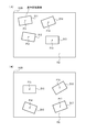
- FIG. 10 is a diagram showing an example of a state in which a plurality of documents are placed on the document table.
- a plurality of documents D1 to D3 are placed on the document table 162.
- FIG. 10A shows a state before the originals D1 to D3 are turned over
- FIG. 10B shows a state after the originals D1 to D3 are turned over.
- P1 to P3 indicate the positions (center points) of the originals D1 to D3 before being turned over
- P4 to P6 in the figure indicate the positions of the originals D1 to D3 after being turned over.
- the rectangles indicated by broken lines in FIG. 10B indicate the placement positions of the documents D1 to D3 before being turned over.
- the documents D1 to D3 are placed at the same place as before being turned over, as shown in FIG. First, the positions P1 to P3 and the positions P4 to P6 do not coincide with each other, and a positional shift may occur.
- the present invention has been made in view of the above circumstances, and improves the accuracy of pair determination for detecting pair images constituting the front and back surfaces of the same document when both surfaces of a plurality of documents are read separately. For the purpose.
- An image reading apparatus includes a document reading unit that can collectively read a plurality of documents placed on a document table, and a document obtained by reading by the document reading unit.
- An individual image cutout unit that performs processing for cutting out an individual image independent for each original from each of the image data of the area and the image data of the other side of the original obtained by turning over the original, and the individual image from the both image data
- a document position detecting unit for detecting the position of each individual image cut out by the image cutting unit; and the image data based on the position of each individual image detected by the document position detecting unit in each of the two image data.
- a reference document image selection unit that selects an individual image located at a location closest to a predetermined position as a reference document image.
- a first relative position detector that detects a relative position indicating a relative positional relationship with respect to the reference document image selected by the reference document image selection unit for each of the individual images other than the reference document image;
- the individual images having the closest relative position from the reference original image in the image data and the relative position from the reference original image in the other image data are pair images constituting the front and back surfaces of the same original.
- a first pair determination unit that performs pair determination.
- An image reading apparatus includes a document reading unit that can collectively read a plurality of documents placed on a document table, and a document obtained by reading by the document reading unit.
- An individual image cutout unit that performs processing for cutting out an individual image independent for each original from each of the image data of the area and the image data of the other side of the original obtained by turning over the original, and the individual image from the both image data
- a document position detection unit for detecting the position of each individual image cut out by the image cutout unit, and each of the two image data based on the position of each individual image detected by the document position detection unit.
- a center-of-gravity detection unit that detects the center of gravity of the aggregate of images, and a relative positional relationship with respect to the center of gravity detected by the center-of-gravity detection unit in each of the image data.
- a second relative position detector that detects a relative position for each of the individual images; the relative position from the centroid in one of the image data; and the relative position from the centroid in the other image data;
- a second pair determination unit that performs pair determination using the individual images closest to each other as a pair image that forms the front and back surfaces of the same document.
- An image reading apparatus includes a document reading unit that can collectively read a plurality of documents placed on a document table, and a document obtained by reading by the document reading unit.
- An individual image cutout unit that performs processing for cutting out an individual image independent for each original from each of the image data of the area and the image data of the other side of the original obtained by turning over the original, and the individual image from the both image data
- a document position detecting unit for detecting the position of each individual image cut out by the image cutting unit; and the image data based on the position of each individual image detected by the document position detecting unit in each of the two image data.
- a reference document image selection unit that selects an individual image located at a location closest to a predetermined position as a reference document image.
- a first relative position detector that detects a relative position indicating a relative positional relationship with respect to the reference document image selected by the reference document image selection unit for each of the individual images other than the reference document image;
- the individual images having the closest relative position from the reference original image in the image data and the relative position from the reference original image in the other image data are pair images constituting the front and back surfaces of the same original.
- a first pair determination unit that performs pair determination, and in each of the two image data, based on the position of each individual image detected by the document position detection unit, the center of gravity of the aggregate composed of the individual images is calculated.
- a second relative position detection unit that detects a relative position of each of the individual images other than the reference original image, the relative position from the center of gravity of one of the image data, and the second image of the image data.
- a second pair determination unit that performs pair determination with the individual images that are closest to the relative position from the center of gravity as a pair image that constitutes the front and back surfaces of the same document; and pair determination by the first pair determination unit; When the pair determination by the second pair determination unit shows the same result, the pair determination is determined to be valid when the pair determination by the first pair determination unit and the second pair determination unit shows the same result.
- An image reading apparatus comprising: an effective determination unit that determines that the pair determination is invalid when the pair determinations by the first pair determination unit and the second pair determination unit indicate different results.
- the accuracy of pair determination for detecting pair images constituting the front and back surfaces of the same document can be improved.
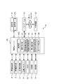
- FIG. 1 is a functional block diagram schematically illustrating a main internal configuration of an image forming apparatus including an image reading apparatus according to a first embodiment of the present invention.
- 5 is a flowchart illustrating an example of a processing operation performed by a control unit in the image forming apparatus including the image reading apparatus according to the first embodiment.
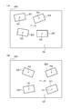
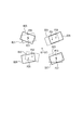
- 2A and 2B are diagrams illustrating an example of a state in which a plurality of documents are placed on a document table, where FIG. 3A illustrates a state before the document is turned over, and FIG. 4B illustrates a state after the document is turned over. Show.
- FIG. 3A illustrates a state before the document is turned over
- FIG. 4B illustrates a state after the document is turned over. Show.
- FIG. 3A illustrates a state before the document is turned over
- FIG. 4B illustrates a state after the document is turned over. Show.
- FIG. 3A illustrates a state before the document is turned over
- FIG. 4B illustrates a state after
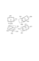
- FIG. 5 is a diagram illustrating a state in which a reversed document and an unturned document are overlapped with the reference document image after being turned over and the reference document image before being turned over as an origin.
- FIG. 6 is a functional block diagram schematically illustrating a main internal configuration of an image forming apparatus including an image reading apparatus according to a second embodiment.
- 10 is a flowchart illustrating an example of a processing operation performed by a control unit in the image forming apparatus that includes the image reading apparatus according to the second embodiment.
- 2A and 2B are diagrams illustrating an example of a state in which a plurality of documents are placed on a document table, where FIG. 3A illustrates a state before the document is turned over, and FIG. 4B illustrates a state after the document is turned over. Show.
- FIG. 5 is a diagram illustrating a state in which a reversed document and a document before being reversed are overlapped with the center of gravity of an assembly including a plurality of documents as an origin.
- FIG. 10 is a functional block diagram schematically illustrating a main internal configuration of an image forming apparatus including an image reading apparatus according to a third embodiment.
- 2A and 2B are diagrams illustrating an example of a state in which a plurality of documents are placed on a document table, where FIG. 3A illustrates a state before the document is turned over, and FIG. 4B illustrates a state after the document is turned over. Show.
- FIG. 6 is a diagram illustrating a state in which a reversed document and a document before being reversed are overlapped.
- FIG. 1 is a functional block diagram schematically showing the main internal configuration of an image forming apparatus including the image reading apparatus according to the first embodiment of the present invention.
- the image forming apparatus 1 is a multifunction machine having a plurality of functions such as a copy function, a printer function, a scanner function, and a facsimile function, and includes a control unit 10, a document feeding unit 6, a document reading unit 5, an image, and the like.
- the image forming apparatus includes a forming unit 12, an image memory 32, an HDD (Hard Disk Drive) 92, a fixing unit 13, a paper feeding unit 14, an operation unit 47, and a network interface unit 91.
- HDD Hard Disk Drive
- the document feeding unit 6 feeds a document to be read to the document reading unit 5.
- the document reading unit 5 uses the light irradiating unit to irradiate the document fed from the document feeding unit 6 or the document placed on the document table 162 (see FIG. 3), and reflects the reflected light. By receiving light, the image is read from the original. Image data obtained by reading by the document reading unit 5 is stored in the image memory 32 or the like.
- the document reading unit 5 is configured to be able to collectively read a plurality of documents placed on the document table 162.
- the image forming unit 12 forms a toner image of an image to be printed on a sheet (recording medium).
- the image memory 32 is an area for temporarily storing image data of a document obtained by reading by the document reading unit 5 and temporarily storing data to be printed by the image forming unit 12. .
- the HDD 92 is a large-capacity storage device that stores document images and the like read by the document reading unit 5.
- the fixing unit 13 fixes the toner image on the paper to the paper by thermocompression bonding.
- the paper supply unit 14 includes a paper supply cassette (not shown), and picks up and conveys the paper stored in the paper supply cassette.
- the operation unit 47 receives instructions such as an image forming operation execution instruction and a document reading operation execution instruction from the operator regarding various operations and processes that can be executed by the image forming apparatus 1.
- the operation unit 47 includes a display unit 473 that displays operation guidance to the operator.
- the display unit 473 is a touch panel, and the operator can operate the image forming apparatus 1 by touching buttons and keys displayed on the screen.
- the network interface unit 91 transmits / receives various data to / from an external device 20 such as a personal computer on the local area or on the Internet.
- the control unit 10 includes a processor, a RAM (Random Access Memory), a ROM (Read Only Memory), and a dedicated hardware circuit.
- the processor is, for example, a CPU (Central Processing Unit), an ASIC (Application Specific Integrated Circuit), or an MPU (Micro Processing Unit).
- the control unit 10 includes a control unit 100, an operation receiving unit 101, an individual image clipping unit 102, a document position detection unit 103, a reference document image selection unit 104, a first relative position detection unit 105, and a first pair. And a determination unit 106.
- the control unit 10 is operated by the processor in accordance with a control program stored in the HDD 92, so that the control unit 100, the operation receiving unit 101, the individual image clipping unit 102, the document position detecting unit 103, the reference document image selecting unit 104, It functions as the first relative position detection unit 105 and the first pair determination unit 106.
- the control unit 100 and the like can be configured by a hardware circuit regardless of the operation of the control unit 10 according to the control program. The same applies to each embodiment unless otherwise specified.
- the control unit 100 controls the overall operation of the image forming apparatus 1.
- the control unit 100 is connected to the document feeding unit 6, the document reading unit 5, the image forming unit 12, the image memory 32, the HDD 92, the fixing unit 13, the sheet feeding unit 14, the operation unit 47, and the network interface unit 91. Drive control of each part is performed.
- the operation reception unit 101 receives an operation input from the user via the operation unit 47.
- the individual image cutout unit 102 obtains image data on one side of the document obtained by reading by the document reading unit 5 and image data on the other side of the document obtained by turning the document upside down (hereinafter, both image data are obtained). Each of the image data) is processed to cut out an individual image independent for each original.
- the individual image cutout unit 102 performs edge detection processing on image data obtained by reading by the document reading unit 5, for example, and detects an edge image.
- the individual image cutout unit 102 obtains a rectangular image that is image data obtained by reading by the document reading unit 5 and has four sides surrounded by the edge image as one block from the image data obtained by detecting the edge image. Cut out as the individual image.
- the document position detection unit 103 detects each individual image corresponding to the individual image clipped by the individual image cutout unit 102 and the position of each individual image. For example, the document position detection unit 103 calculates the position of the individual image from the coordinate position of the individual image in the image data obtained by reading by the document reading unit 5. In the present embodiment, the document position detection unit 103 determines the center position of each individual image (in this embodiment, each individual image is a rectangular image, so the position where the diagonal lines intersect is the center position). Detect as position.
- the reference document image selection unit 104 Based on the position of each individual image detected by the document position detection unit 103 in each of the two image data, the reference document image selection unit 104 is set at a predetermined position (for example, the left back corner) in the image data. The individual image located at the closest location is selected as the reference document image.
- the first relative position detection unit 105 determines a relative position indicating a relative positional relationship with respect to the reference document image selected by the reference document image selection unit 104 in each of the two image data other than the reference document image. Each individual image is detected.
- the first pair determination unit 106 uses the same individual images that are closest to the relative position from the reference document image in one of the image data and the relative position from the reference document image in the other image data. Pair determination is performed with a pair image constituting the front and back sides of the document.
- This processing operation is a processing operation that is performed when the operation receiving unit 101 receives an instruction to read both sides of a document placed on the document table 162, which is instructed by the user via the operation unit 47.
- control unit 100 causes the document reading unit 5 to read a document placed on the document table 162, and stores the image data obtained by reading by the document reading unit 5 in the image memory 32 (S1). .
- image data is acquired by reading one side of the document by the document reading unit 5.
- the individual image cutout unit 102 cuts out an individual image independent for each document from the image data obtained by reading by the document reading unit 5, and stores the image data of the cut out individual image in the image memory 32 (S2). ).
- the document position detecting unit 103 detects the position (the center position) of each individual image cut out by the individual image cutting unit 102 (S3).
- the reference document image selection unit 104 uses the image data read in S1 in the left back corner 162A of the document table 162 (see FIG. 3). An individual image located at a location closest to the corresponding position is selected as a reference document image (S4).
- the first relative position detection unit 105 calculates the relative position of each individual image other than the reference document image with respect to the reference document image selected by the reference document image selection unit 104 in the image data read in S1. Detection is performed based on the reference original image and the center position of each individual image (S5).
- the first relative position detection unit 105 detects the relative positions of the individual images corresponding to the other documents D11 to D14 with respect to the individual image corresponding to the document D11 serving as the reference document image.
- the first relative position detection unit 105 causes the relative position of the individual image corresponding to the document D12 to the individual image corresponding to the document D11 and the relative position of the individual image corresponding to the document D12 to the individual image corresponding to the document D11.
- the relative position of the individual image corresponding to the document D13 with respect to the individual image corresponding to the document D11 and the relative position of the individual image corresponding to the document D14 with respect to the individual image corresponding to the document D11 are detected. That is, the first relative position detection unit 105 detects the positions of the individual images corresponding to the documents D12 to D14 when the center point (position P11) of the individual image corresponding to the document D11 is the origin.
- P11 to P14 indicate the positions (center points) of the documents D11 to D14.
- control unit 100 determines whether or not the operation receiving unit 101 has received a re-reading instruction for the document placed on the document table 162, which is instructed by the user via the operation unit 47 ( S6). It should be noted that the user turns over each document placed on the document table 162 before inputting the re-reading instruction to the operation unit 47.
- the document reading unit 5 When the control unit 100 determines that the instruction has been received by the operation receiving unit 101 (YES in S6), the document reading unit 5 is caused to read the document placed on the document table, and the document reading unit 5 The image data obtained by the reading by the above is stored in the image memory 32 (S7). Since this instruction is performed after the user turns over the originals D11 to D14, the original reading unit 5 is caused to read the inverted originals D11 to D14, that is, the other side of the originals D11 to D14. .
- the individual image cutout unit 102 cuts out individual images independent for each document from the image data obtained by reading by the document reading unit 5, and the image data of the cut out individual images is displayed as image data.
- the document position detection unit 103 stores the image in the memory 32 (S8), and detects the position of each individual image corresponding to the individual image cut out by the individual image cutout unit 102 (S9).
- the reference document image selection unit 104 determines the left back corner 162A of the document table 162 in the document image data read in S7 (FIG. 3B). )) Is selected as a reference original image (S10).
- the first relative position detection unit 105 determines the relative position of each individual image other than the reference document image with respect to the reference document image selected by the reference document image selection unit 104 in the image data of the document read in S7. Detection is based on the reference original image and the center position of each individual image (S11).
- the originals placed in the place closest to the left back corner 162A of the original table 162.
- the individual image corresponding to D15 is selected by the reference document image selection unit 104 as the reference document image, and the relative position of the individual image corresponding to the other documents D15 to D18 with respect to the individual image corresponding to the document D15 serving as the reference document image. Is detected by the first relative position detector 105.
- the first relative position detection unit 105 causes the relative position of the individual image corresponding to the document D15 to the individual image corresponding to the document D15 and the relative position of the individual image corresponding to the document D16 to the individual image corresponding to the document D15. Then, the relative position of the individual image corresponding to the document D17 relative to the individual image corresponding to the document D15 and the relative position of the individual image corresponding to the document D18 relative to the individual image corresponding to the document D15 are detected. That is, the first relative position detector 105 detects the positions of the individual images corresponding to the documents D16 to D18 when the center point (position P15) of the individual image corresponding to the document D15 is the origin. In the figure, P15 to P18 indicate the positions (center points) of the documents D15 to D18.
- the first pair determination unit 106 has a relative position from the reference document image in one image data obtained by the reading of S1 and a relative position from the reference document image in the other image data obtained in S7.
- An individual image having a value closest to the position is selected from each of the one and other image data, and pair determination is performed using the selected individual images as a pair image constituting the front and back surfaces of the same document ( S12).
- the control unit 100 stores the image data of the individual images stored in the image memory 32 for each pair, for example, a storage area designated by the user, for example, the HDD 92.
- the data is stored in the external device 20 (for example, a personal computer) via the network interface unit 91 (S13).
- FIG. 4A and 4B show an individual image corresponding to an inverted document with the reference document image turned upside down and the reference document image before being turned upside down as the origin in the example shown in FIGS. 3A and 3B.
- FIG. 5 is a diagram showing a state in which an individual image corresponding to a document before being turned upside down is overlaid.
- the first pair determination unit 106 first performs pair determination on an individual image corresponding to the document D11 in one image data obtained by reading S1.
- the first relative position detection unit 105 performs the individual image corresponding to the document D11 with respect to the reference document image. Is detected as “0”.
- the individual image corresponding to the document D15 itself is the reference document image, so the first relative position detection unit 105 performs the individual image corresponding to the document D15 with respect to the reference document image.
- the relative position of the image is detected as “0”. Therefore, the first pair determination unit 106 determines that the individual image corresponding to the document D11 whose relative position is “0” and the individual image corresponding to the document D15 are a pair.
- the first pair determination unit 106 performs pair determination on an individual image corresponding to the document D12 in one image data obtained by reading S1.
- the first pair determination unit 106 selects an individual image whose relative position closest to the relative position of the individual image corresponding to the document D12 is detected with respect to the reference document image D11 in one of the image data obtained by the reading of S1.
- S7 is detected from the individual images included in the other image data obtained by the reading in S7.
- the first pair determination unit 106 corresponds to the individual image corresponding to the document D12 and the document D16, which are the individual images having the smallest relative position values.
- the individual images to be determined are determined as a pair.
- the first pair determination unit 106 performs pair determination on the individual image corresponding to the document D13 in one of the image data obtained by reading S1.
- the first pair determination unit 106 selects an individual image whose relative position closest to the relative position of the individual image corresponding to the document D13 is detected with respect to the reference document image D11 in one of the image data obtained by the reading of S1.
- S7 is detected from the individual images included in the other image data obtained by the reading in S7.
- the first pair determination unit 106 corresponds to the individual image corresponding to the document D13 and the document D17, which are individual images having the smallest relative position values.
- the individual images to be determined are determined as a pair.
- the first pair determination unit 106 performs pair determination on an individual image corresponding to the document D14 in one image data obtained by reading S1.
- the first pair determination unit 106 selects an individual image whose relative position closest to the relative position of the individual image corresponding to the document D14 is detected with respect to the reference document image D11 in one of the image data obtained by the reading of S1.
- S7 is detected from the individual images included in the other image data obtained by the reading in S7.
- the first pair determination unit 106 corresponds to the individual image corresponding to the document D14 and the document D18, which are individual images having the smallest relative position value.
- the individual images to be determined are determined as a pair.
- the first pair determination unit 106 corresponds to the individual image corresponding to the document D14 in one image data obtained by the reading of S1 and the document D18 remaining in the other image data obtained by the reading of S7.
- the individual images to be determined may be determined as a pair.
- the individual images having the closest relative positions are obtained from the one and the other image data. Then, pair determination is performed as a pair image constituting the front and back surfaces of the same document. That is, the relationship between the positions of the originals on the original table 162 that does not change much before and after the user turns over the originals on the original table 162 (this reference when one original among a plurality of originals is used as a reference). Based on the relative position of the other originals with respect to the original, a pair determination is made as to whether the images constituting the front and back surfaces of the same original are the same, so that the accuracy of the pair determination is improved.
- FIG. 5 is a functional block diagram schematically showing the main internal configuration of the image forming apparatus including the image reading apparatus according to the second embodiment of the present invention.
- Components similar to those of the image forming apparatus 1 shown in FIG. 1 are denoted by the same reference numerals, and detailed description thereof is omitted here.
- the reference document image is used as the origin.
- the second embodiment is different from the first embodiment in that the center of gravity of an assembly composed of a plurality of documents is used as the origin.
- the image forming apparatus 1A is a multifunction machine having a plurality of functions such as a copy function, a printer function, a scanner function, and a facsimile function, and includes a control unit 10A, a document feeding unit 6, a document reading unit 5, and an image.
- the image forming apparatus includes a forming unit 12, an image memory 32, an HDD 92, a fixing unit 13, a paper feeding unit 14, an operation unit 47, and a network interface unit 91.
- the control unit 10A is operated by the processor in accordance with a control program stored in the HDD 92.
- the control unit 100A, the operation receiving unit 101, the individual image clipping unit 102, the document position detecting unit 103, the center of gravity detecting unit 107, the second It functions as the relative position detection unit 108 and the second pair determination unit 109.
- the control unit 100A controls the overall operation of the image forming apparatus 1A.
- the control unit 100A is connected to the document feeding unit 6, the document reading unit 5, the image forming unit 12, the image memory 32, the HDD 92, the fixing unit 13, the sheet feeding unit 14, the operation unit 47, and the network interface unit 91. Drive control of each part is performed.
- the center-of-gravity detection unit 107 detects the center of gravity of the aggregate composed of the individual images detected by the document position detection unit 103 in both the image data. For example, the center point of the figure formed by connecting the center positions of the individual images detected by the document position detection unit 103 with a straight line is detected as the center of gravity of the aggregate.
- the second relative position detection unit 108 detects, in each of the individual images, a relative position indicating a relative positional relationship with respect to the center of gravity detected by the center of gravity detection unit 107 in both the image data.
- the second pair determination unit 109 displays the individual images that are closest to the relative position from the centroid in one image data and the relative position from the centroid in the other image data. Pair determination is performed with a pair image constituting the back surface.
- This processing operation is a processing operation that is performed when the operation receiving unit 101 receives an instruction to read both sides of a document placed on the document table 162, which is instructed by the user via the operation unit 47.
- control unit 100A causes the document reading unit 5 to read a document placed on the document table 162, and stores the image data obtained by reading by the document reading unit 5 in the image memory 32 (S21). .
- image data is acquired by reading one side of the document by the document reading unit 5.
- the individual image cutout unit 102 cuts out an individual image independent for each document from the image data obtained by reading by the document reading unit 5, and stores the image data of the cut out individual image in the image memory 32 (S22). ).
- the document position detecting unit 103 detects the position of each individual image corresponding to the individual image cut out by the individual image cutting unit 102 (S23).
- the center-of-gravity detection unit 107 detects the center of gravity of the aggregate composed of the individual images detected by the document position detection unit 103 (S24).
- the second relative position detector 108 detects the relative position between the centroid G1 detected by the centroid detector 107 and each individual image (S25).
- the center of gravity G1 of the aggregate composed of individual images corresponding to the documents D21 to D24 is detected as the center of gravity.
- the relative position between the gravity center G1 and the individual images corresponding to the originals D21 to D24 is detected by the second relative position detector 108. That is, the relative position of each individual image corresponding to the originals D21 to D24 with respect to the center of gravity G1 when the center of gravity G1 is the origin is detected by the second relative position detector 108.
- the second relative position detection unit 108 uses the relative position of the individual image corresponding to the document D21 relative to the center of gravity G1, the relative position of the individual image corresponding to the document D22 relative to the center of gravity G1, and the individual corresponding to the document D23 relative to the center of gravity G1.
- the relative position of the image and the relative position of the individual image corresponding to the document D24 with respect to the center of gravity G1 are detected.
- P21 to P24 indicate the positions (center points) of the documents D21 to D24.
- control unit 100A determines whether or not the operation receiving unit 101 has received an instruction to read a document placed on the document table 162, which is instructed by the user via the operation unit 47 (S26). . It should be noted that the user turns over each document placed on the document table 162 before inputting the re-reading instruction to the operation unit 47.
- the control unit 100A causes the document reading unit 5 to read the document placed on the document table, and the document reading unit 5
- the image data obtained by the reading is stored in the image memory 32 (S27). Since this instruction is performed after the user turns over the originals D11 to D14, the original reading unit 5 is caused to read the inverted originals D11 to D14, that is, the other side of the originals D11 to D14. .
- the individual image cutout unit 102 cuts out an individual image independent for each original from the image data obtained by reading by the original reading unit 5, and the image data of the cut out individual image is displayed as an image.
- the data is stored in the memory 32 (S28).
- the document position detection unit 103 detects the position of each individual image cut out by the individual image cutting unit 102 (S29).
- the center-of-gravity detection unit 107 detects the center of gravity G2 of the aggregate composed of the individual images based on the center position of each individual image detected by the document position detection unit 103 (S30).
- the second relative position detection unit 108 detects the relative position between the center of gravity G2 detected by the center of gravity detection unit 107 and each individual image (S31).
- the center of gravity G2 of the aggregate composed of individual images corresponding to the documents D25 to D28 is detected.
- the relative position between the center of gravity G2 and the individual images corresponding to the originals D25 to D28 is detected. That is, the relative position of each of the individual images corresponding to the originals D25 to D28 with respect to the center of gravity G2 when the center of gravity G2 is the origin is detected by the second relative position detector 108.
- the second relative position detection unit 108 uses the relative position of the individual image corresponding to the document D25 with respect to the center of gravity G2, the relative position of the individual image corresponding to the document D26 with respect to the center of gravity G2, and the individual position corresponding to the document D27 with respect to the center of gravity G2.
- the relative position of the image and the relative position of the individual image corresponding to the document D28 with respect to the center of gravity G2 are detected.
- P25 to P28 indicate the positions (center points) of the individual images corresponding to the documents D25 to D28.
- the second pair determination unit 109 uses the center of gravity G1 as the origin and the relative position from the center of gravity G1 in the one image data acquired in S21, and the center of gravity G2 as the origin and the other acquired in S27. Pair determination is performed in which the individual images that are closest to the relative position from the center of gravity G2 in the image data are paired images constituting the front and back surfaces of the same document (S32).
- the control unit 100A stores the image data of the individual images stored in the image memory 32 for each pair, for example, a storage area designated by the user, for example, the HDD 92.
- the data is stored in the external device 20 (for example, a personal computer) via the network interface unit 91 (S33).
- FIG. 8 shows a state in which the individual image corresponding to the reversed document and the individual image corresponding to the document before being reversed are overlapped with the center of gravity of the aggregate of individual images corresponding to a plurality of documents as the origin.
- FIG. An example of the pair determination process performed by the second pair determination unit 109 will be described with reference to FIG. First determination process
- the second pair determination unit 109 first performs pair determination on the individual image corresponding to the document D21 in one of the image data obtained by reading in S21.
- the second pair determination unit 109 detects an individual image in which the relative position closest to the relative position of the individual image corresponding to the document D21 with respect to the center of gravity G1 in one of the image data obtained by the reading in S21 is detected in S27. Are detected from the individual images included in the other image data obtained by reading. In the example shown in FIGS. 7A and 7B, the second pair determination unit 109 determines that the individual image corresponding to the document D21 and the individual image corresponding to the document D25 are a pair.
- the second pair determination unit 109 performs pair determination on an individual image corresponding to the document D22 in one image data obtained by reading in S21.
- the second pair determination unit 109 detects an individual image in which the relative position closest to the relative position of the individual image corresponding to the document D22 with respect to the center of gravity G1 in one of the image data obtained by the reading in S21 is detected in S27. Are detected from the individual images included in the other image data obtained by reading.
- the second pair determination unit 109 determines that the individual image corresponding to the document D22 and the individual image corresponding to the document D26 are a pair.
- the second pair determination unit 109 performs pair determination on an individual image corresponding to the document D23 in one image data obtained by reading in S21.
- the second pair determination unit 109 detects an individual image in which the relative position closest to the relative position of the individual image corresponding to the document D23 with respect to the center of gravity G1 in one of the image data obtained by the reading in S21 is detected in S27. Are detected from the individual images included in one of the image data obtained by the reading.
- the second pair determination unit 109 determines that the individual image corresponding to the document D23 and the individual image corresponding to the document D27 are a pair.
- the second pair determination unit 109 performs pair determination on the individual image corresponding to the document D24 in one image data obtained by reading in S21.
- the second pair determination unit 109 detects an individual image in which the relative position closest to the relative position of the individual image corresponding to the document D24 with respect to the center of gravity G1 in one of the image data obtained by the reading in S21 is detected in S27. Are detected from the individual images included in one of the image data obtained by the reading.
- the second pair determination unit 109 determines that the individual image corresponding to the document D24 and the individual image corresponding to the document D28 are a pair.
- the second pair determination unit 109 uses the individual image corresponding to the document D24 in the one image data obtained by the reading of S21 and the other obtained by the reading of S27.
- the individual images corresponding to the document D28 remaining in the image data may be determined as a pair.
- the center of gravity is calculated from each of the one image data and the other image data based on the relative position between the individual images and the center of gravity G1, G2 of the aggregate composed of individual images corresponding to a plurality of documents.
- Pair determination is performed in which the individual images that are closest to each other are paired images that form the front and back surfaces of the same document. That is, based on the relationship of the document position on the document table 162 (relative position of each document with respect to the center of gravity) that does not change much before and after the user turns over the document on the document table 162, Since pair determination is performed as to whether or not the images constitute the front and back surfaces, the accuracy of the pair determination is improved.
- the present invention is not limited to the configuration of the above embodiment, and various modifications can be made.
- the first pair determination unit 106 performs pair determination based on the relative positional relationship
- the second pair determination unit 109 performs pair determination based on the center of gravity.
- the image forming apparatus 1 according to the third embodiment is shown as the second embodiment as shown in FIG.
- An image forming apparatus that includes the center-of-gravity detection unit 107, the second relative position detection unit 108, and the second pair determination unit 109, and further includes the validity determination unit 110 may be employed.
- the control unit 10 is operated by the processor in accordance with a control program stored in the HDD 92, so that the control unit 100, the operation receiving unit 101, the individual image clipping unit 102, the document position detecting unit 103, the reference document image selecting unit 104, It functions as the first relative position detection unit 105, the first pair determination unit 106, the center of gravity detection unit 107, the second relative position detection unit 108, the second pair determination unit 109, and the validity determination unit 110.
- the validity determination unit 110 when the pair determination by the first pair determination unit 106 and the pair determination by the second pair determination unit 109 show the same result, the first pair determination unit 106 and the second pair determination unit 109, when the pair determination by the first pair determination unit 106 and the second pair determination unit 109 shows different results, the pair by the first pair determination unit 106 and the second pair determination unit 109 It is determined that the determination is invalid.
- the validity determination unit 110 for all the individual images of a plurality of documents, only when the pair determination by the first pair determination unit 106 and the second pair determination unit 109 shows the same result, the individual images of the plurality of documents. It is determined that the pair determination by the first pair determination unit 106 and the second pair determination unit 109 for all of these is valid. Then, the validity determination unit 110, when one of the individual images of a plurality of documents shows a different pair determination by the first pair determination unit 106 and the second pair determination unit 109, the individual image of another document All the pair determinations including the pair determination by the first pair determination unit 106 and the second pair determination unit 109 are determined to be invalid. Thereby, the precision of pair determination further improves.
- the validity determination unit 110 also determines that any one of the individual images of a plurality of documents has a result of different pair determinations by the first pair determination unit 106 and the second pair determination unit 109. For individual images, even if the pair determination by the first pair determination unit 106 and the second pair determination unit 109 shows the same result, the pair by the second pair determination unit 109 for all the individual images of a plurality of documents. You may make it determine with determination being effective. In this case, the control unit 100 may display on the display unit 473 that the pair determination by the second pair determination unit 109 has been determined to be valid.
- the validity determination unit 110 may determine validity / invalidity as follows. For example, with reference to the example shown in FIGS. 3A and 3B, the first pair determination unit 106 determines that the individual image of the document D11 and the individual image of the document D15 are a pair, and the individual of the document D12. Assume that the image and the individual image of the document D16 are determined as a pair, the individual image of the document D13 and the individual image of the document D17 are determined as a pair, and the individual image of the document D14 and the individual image of the document D18 are determined as a pair.
- the second pair determination unit 109 determines the individual image of the document D11 and the individual image of the document D15 as a pair, determines the individual image of the document D12 and the individual image of the document D16 as a pair, and determines the individual image of the document D13.
- the validity determination unit 110 determines the individual of the document D11 having the same determination result.
- pair determination of the image and the individual image of the document D15 and the pair determination of the individual image of the document D12 and the individual image of the document D16 are valid, and the pair determination is invalid for each of the individual images of the documents D13, D14, D17, and D18. Is determined. Thereby, the accuracy of pair determination can be improved for each original.
- FIGS. 1 to 11 are only one embodiment of the present invention, and are not intended to limit the present invention to the configuration and processing.
Landscapes
- Engineering & Computer Science (AREA)
- Multimedia (AREA)
- Signal Processing (AREA)
- Facsimile Scanning Arrangements (AREA)
- Facsimiles In General (AREA)
- Image Analysis (AREA)
- Editing Of Facsimile Originals (AREA)
- Image Input (AREA)
Abstract
L'invention concerne un dispositif de formation d'image (1) comprenant : une unité de lecture de manuscrit (5) capable de lire au moins une pluralité de manuscrits placés sur une base de manuscrit (162) ; une unité de sélection d'image de manuscrit de référence (104) qui sélectionne, en tant qu'image de manuscrit de référence, une image individuelle associée à un manuscrit (D11, D15) positionné à un emplacement le plus proche d'une position correspondant au coin arrière gauche (162A) de la base de manuscrit (162) ; une première unité de détection de position relative (105) qui détecte une position relative entre l'image de manuscrit de référence (D11, D15) et chacune des images individuelles autres que l'image de manuscrit de référence ; et une première unité de détermination de paire (106) qui effectue une détermination de paire dans laquelle des images individuelles dont la position relative à partir de l'image de manuscrit de référence dans une donnée d'image et la position relative à partir de l'image de manuscrit de référence dans les autres données d'image sont les plus proches l'une de l'autre sont considérées comme des images de paire constituant les surfaces avant et arrière du même manuscrit.
Priority Applications (4)
| Application Number | Priority Date | Filing Date | Title |
|---|---|---|---|
| JP2018559556A JP6711420B2 (ja) | 2016-12-28 | 2017-12-26 | 画像読取装置 |
| CN201780080403.3A CN110115020B (zh) | 2016-12-28 | 2017-12-26 | 图像读取装置 |
| US16/473,408 US10701235B2 (en) | 2016-12-28 | 2017-12-26 | Document reading device identifying front and back faces of same document based on relative positions of center of gravity of cropped images |
| EP17886376.7A EP3565231B1 (fr) | 2016-12-28 | 2017-12-26 | Dispositif de lecture d'image |
Applications Claiming Priority (2)
| Application Number | Priority Date | Filing Date | Title |
|---|---|---|---|
| JP2016-256864 | 2016-12-28 | ||
| JP2016256864 | 2016-12-28 |
Publications (1)
| Publication Number | Publication Date |
|---|---|
| WO2018124146A1 true WO2018124146A1 (fr) | 2018-07-05 |
Family
ID=62708123
Family Applications (1)
| Application Number | Title | Priority Date | Filing Date |
|---|---|---|---|
| PCT/JP2017/046811 Ceased WO2018124146A1 (fr) | 2016-12-28 | 2017-12-26 | Dispositif de lecture d'image |
Country Status (5)
| Country | Link |
|---|---|
| US (1) | US10701235B2 (fr) |
| EP (1) | EP3565231B1 (fr) |
| JP (1) | JP6711420B2 (fr) |
| CN (1) | CN110115020B (fr) |
| WO (1) | WO2018124146A1 (fr) |
Cited By (3)
| Publication number | Priority date | Publication date | Assignee | Title |
|---|---|---|---|---|
| JP2020014179A (ja) * | 2018-07-20 | 2020-01-23 | 京セラドキュメントソリューションズ株式会社 | 画像形成装置 |
| WO2020235184A1 (fr) * | 2019-05-17 | 2020-11-26 | 京セラドキュメントソリューションズ株式会社 | Dispositif de lecture d'image |
| JP2022046741A (ja) * | 2017-11-07 | 2022-03-23 | シャープ株式会社 | 画像処理装置 |
Families Citing this family (1)
| Publication number | Priority date | Publication date | Assignee | Title |
|---|---|---|---|---|
| JP7476557B2 (ja) * | 2020-02-14 | 2024-05-01 | 株式会社リコー | 機器、処理実行システム、処理実行方法、プログラム |
Citations (5)
| Publication number | Priority date | Publication date | Assignee | Title |
|---|---|---|---|---|
| JP2006339770A (ja) | 2005-05-31 | 2006-12-14 | Canon Inc | 画像処理システムおよびその制御方法 |
| JP2009100211A (ja) * | 2007-10-16 | 2009-05-07 | Sharp Corp | 画像読取装置及び画像読取方法 |
| JP2013250725A (ja) | 2012-05-31 | 2013-12-12 | Brother Ind Ltd | 画像読取装置 |
| JP2015056794A (ja) * | 2013-09-12 | 2015-03-23 | 株式会社リコー | 情報処理装置、情報処理システム、情報処理方法およびプログラム |
| JP2015127936A (ja) * | 2013-11-28 | 2015-07-09 | 株式会社リコー | 画像処理システム、情報処理装置及びプログラム |
Family Cites Families (10)
| Publication number | Priority date | Publication date | Assignee | Title |
|---|---|---|---|---|
| JP4386281B2 (ja) * | 2005-01-31 | 2009-12-16 | キヤノン株式会社 | 画像処理方法及び画像処理装置並びにプログラム |
| JP2008113075A (ja) * | 2006-10-27 | 2008-05-15 | Canon Inc | 画像処理装置およびその制御方法 |
| JP6074307B2 (ja) * | 2013-04-05 | 2017-02-01 | 凸版印刷株式会社 | カラー画像処理装置 |
| JP6807630B2 (ja) * | 2016-12-12 | 2021-01-06 | シャープ株式会社 | 画像読取装置及び複合機、画像読取方法並びに画像読取用プログラム |
| JP6837347B2 (ja) * | 2017-02-15 | 2021-03-03 | シャープ株式会社 | 画像読取装置および画像読取方法 |
| JP6964486B2 (ja) * | 2017-11-02 | 2021-11-10 | シャープ株式会社 | 画像処理装置 |
| JP6913606B2 (ja) * | 2017-11-02 | 2021-08-04 | シャープ株式会社 | 画像処理装置 |
| JP6986946B2 (ja) * | 2017-12-13 | 2021-12-22 | シャープ株式会社 | 原稿読取装置 |
| JP6991072B2 (ja) * | 2018-01-31 | 2022-01-12 | シャープ株式会社 | 画像読取装置、画像形成装置および制御方法 |
| JP7155705B2 (ja) * | 2018-07-20 | 2022-10-19 | 京セラドキュメントソリューションズ株式会社 | 画像形成装置 |
-
2017
- 2017-12-26 EP EP17886376.7A patent/EP3565231B1/fr not_active Not-in-force
- 2017-12-26 JP JP2018559556A patent/JP6711420B2/ja not_active Expired - Fee Related
- 2017-12-26 CN CN201780080403.3A patent/CN110115020B/zh not_active Expired - Fee Related
- 2017-12-26 US US16/473,408 patent/US10701235B2/en not_active Expired - Fee Related
- 2017-12-26 WO PCT/JP2017/046811 patent/WO2018124146A1/fr not_active Ceased
Patent Citations (5)
| Publication number | Priority date | Publication date | Assignee | Title |
|---|---|---|---|---|
| JP2006339770A (ja) | 2005-05-31 | 2006-12-14 | Canon Inc | 画像処理システムおよびその制御方法 |
| JP2009100211A (ja) * | 2007-10-16 | 2009-05-07 | Sharp Corp | 画像読取装置及び画像読取方法 |
| JP2013250725A (ja) | 2012-05-31 | 2013-12-12 | Brother Ind Ltd | 画像読取装置 |
| JP2015056794A (ja) * | 2013-09-12 | 2015-03-23 | 株式会社リコー | 情報処理装置、情報処理システム、情報処理方法およびプログラム |
| JP2015127936A (ja) * | 2013-11-28 | 2015-07-09 | 株式会社リコー | 画像処理システム、情報処理装置及びプログラム |
Non-Patent Citations (1)
| Title |
|---|
| See also references of EP3565231A4 |
Cited By (4)
| Publication number | Priority date | Publication date | Assignee | Title |
|---|---|---|---|---|
| JP2022046741A (ja) * | 2017-11-07 | 2022-03-23 | シャープ株式会社 | 画像処理装置 |
| JP2020014179A (ja) * | 2018-07-20 | 2020-01-23 | 京セラドキュメントソリューションズ株式会社 | 画像形成装置 |
| JP7155705B2 (ja) | 2018-07-20 | 2022-10-19 | 京セラドキュメントソリューションズ株式会社 | 画像形成装置 |
| WO2020235184A1 (fr) * | 2019-05-17 | 2020-11-26 | 京セラドキュメントソリューションズ株式会社 | Dispositif de lecture d'image |
Also Published As
| Publication number | Publication date |
|---|---|
| EP3565231B1 (fr) | 2022-06-22 |
| US10701235B2 (en) | 2020-06-30 |
| JPWO2018124146A1 (ja) | 2019-10-31 |
| EP3565231A1 (fr) | 2019-11-06 |
| JP6711420B2 (ja) | 2020-06-17 |
| CN110115020B (zh) | 2021-03-12 |
| EP3565231A4 (fr) | 2020-08-19 |
| US20200145552A1 (en) | 2020-05-07 |
| CN110115020A (zh) | 2019-08-09 |
Similar Documents
| Publication | Publication Date | Title |
|---|---|---|
| JP5874465B2 (ja) | 情報処理装置、画像形成装置、情報処理装置の制御方法、画像形成装置の制御方法、情報処理装置の制御プログラム、及び画像形成装置の制御プログラム | |
| JP6711420B2 (ja) | 画像読取装置 | |
| JP6885111B2 (ja) | 画像処理装置および画像形成装置 | |
| JP4853399B2 (ja) | 画像処理装置、画像処理方法および画像処理プログラム | |
| JP6500863B2 (ja) | 画像形成装置 | |
| JP2021128356A (ja) | 情報処理装置及びプログラム | |
| KR20130061604A (ko) | 화상형성장치, 화상형성방법 및 기록 매체 | |
| JP6592873B2 (ja) | 画像読取装置、画像形成装置、画像読取方法及び画像読取プログラム | |
| JP2008276277A (ja) | 操作表示装置及び画像形成装置 | |
| JP2020061619A (ja) | 画像読取装置 | |
| JP2011166778A (ja) | 画像形成装置、画像補正方法およびそのプログラム | |
| JP6648839B2 (ja) | 画像読取装置 | |
| JP5831715B2 (ja) | 操作装置および画像処理装置 | |
| JP6639257B2 (ja) | 情報処理装置及びその制御方法 | |
| JP2020021273A (ja) | 画像読取装置 | |
| JP6213581B2 (ja) | 情報処理装置及び情報処理装置の制御プログラム | |
| US10192090B2 (en) | Information processing device, image reading apparatus and non-transitory computer readable medium storing program for scanning based on a code image | |
| JP2017204189A (ja) | 電子機器及び画像形成装置 | |
| JP6260177B2 (ja) | 画像処理システム、画像処理方法、及び画像処理プログラム | |
| JP5335561B2 (ja) | 出力制御装置、その制御方法及びプログラム | |
| JP4888251B2 (ja) | 画像処理装置および画像処理方法 | |
| US20240345681A1 (en) | Information processing system, information processing method, and non-transitory computer readable medium | |
| JP6508121B2 (ja) | 画像処理装置、画像処理装置の機能設定方法 | |
| JP2019028508A (ja) | 情報処理装置及びプログラム | |
| JP2025145526A (ja) | 画像形成システム及びプログラム |
Legal Events
| Date | Code | Title | Description |
|---|---|---|---|
| 121 | Ep: the epo has been informed by wipo that ep was designated in this application |
Ref document number: 17886376 Country of ref document: EP Kind code of ref document: A1 |
|
| ENP | Entry into the national phase |
Ref document number: 2018559556 Country of ref document: JP Kind code of ref document: A |
|
| NENP | Non-entry into the national phase |
Ref country code: DE |
|
| ENP | Entry into the national phase |
Ref document number: 2017886376 Country of ref document: EP Effective date: 20190729 |