WO2018134893A1 - 作業機 - Google Patents
作業機 Download PDFInfo
- Publication number
- WO2018134893A1 WO2018134893A1 PCT/JP2017/001414 JP2017001414W WO2018134893A1 WO 2018134893 A1 WO2018134893 A1 WO 2018134893A1 JP 2017001414 W JP2017001414 W JP 2017001414W WO 2018134893 A1 WO2018134893 A1 WO 2018134893A1
- Authority
- WO
- WIPO (PCT)
- Prior art keywords
- frame
- pair
- base
- columns
- head
- Prior art date
- Legal status (The legal status is an assumption and is not a legal conclusion. Google has not performed a legal analysis and makes no representation as to the accuracy of the status listed.)
- Ceased
Links
Images




Classifications
-
- H—ELECTRICITY
- H05—ELECTRIC TECHNIQUES NOT OTHERWISE PROVIDED FOR
- H05K—PRINTED CIRCUITS; CASINGS OR CONSTRUCTIONAL DETAILS OF ELECTRIC APPARATUS; MANUFACTURE OF ASSEMBLAGES OF ELECTRICAL COMPONENTS
- H05K13/00—Apparatus or processes specially adapted for manufacturing or adjusting assemblages of electric components
- H05K13/04—Mounting of components, e.g. of leadless components
- H05K13/0452—Mounting machines or lines comprising a plurality of tools for guiding different components to the same mounting place
-
- H—ELECTRICITY
- H05—ELECTRIC TECHNIQUES NOT OTHERWISE PROVIDED FOR
- H05K—PRINTED CIRCUITS; CASINGS OR CONSTRUCTIONAL DETAILS OF ELECTRIC APPARATUS; MANUFACTURE OF ASSEMBLAGES OF ELECTRICAL COMPONENTS
- H05K13/00—Apparatus or processes specially adapted for manufacturing or adjusting assemblages of electric components
- H05K13/04—Mounting of components, e.g. of leadless components
- H05K13/0404—Pick-and-place heads or apparatus, e.g. with jaws
- H05K13/0406—Drive mechanisms for pick-and-place heads, e.g. details relating to power transmission, motors or vibration damping
-
- B—PERFORMING OPERATIONS; TRANSPORTING
- B25—HAND TOOLS; PORTABLE POWER-DRIVEN TOOLS; MANIPULATORS
- B25J—MANIPULATORS; CHAMBERS PROVIDED WITH MANIPULATION DEVICES
- B25J9/00—Program-controlled manipulators
- B25J9/02—Program-controlled manipulators characterised by movement of the arms, e.g. cartesian coordinate type
-
- H—ELECTRICITY
- H05—ELECTRIC TECHNIQUES NOT OTHERWISE PROVIDED FOR
- H05K—PRINTED CIRCUITS; CASINGS OR CONSTRUCTIONAL DETAILS OF ELECTRIC APPARATUS; MANUFACTURE OF ASSEMBLAGES OF ELECTRICAL COMPONENTS
- H05K13/00—Apparatus or processes specially adapted for manufacturing or adjusting assemblages of electric components
- H05K13/04—Mounting of components, e.g. of leadless components
-
- H—ELECTRICITY
- H05—ELECTRIC TECHNIQUES NOT OTHERWISE PROVIDED FOR
- H05K—PRINTED CIRCUITS; CASINGS OR CONSTRUCTIONAL DETAILS OF ELECTRIC APPARATUS; MANUFACTURE OF ASSEMBLAGES OF ELECTRICAL COMPONENTS
- H05K13/00—Apparatus or processes specially adapted for manufacturing or adjusting assemblages of electric components
- H05K13/04—Mounting of components, e.g. of leadless components
- H05K13/0404—Pick-and-place heads or apparatus, e.g. with jaws
- H05K13/0408—Incorporating a pick-up tool
- H05K13/0409—Sucking devices
-
- H—ELECTRICITY
- H05—ELECTRIC TECHNIQUES NOT OTHERWISE PROVIDED FOR
- H05K—PRINTED CIRCUITS; CASINGS OR CONSTRUCTIONAL DETAILS OF ELECTRIC APPARATUS; MANUFACTURE OF ASSEMBLAGES OF ELECTRICAL COMPONENTS
- H05K13/00—Apparatus or processes specially adapted for manufacturing or adjusting assemblages of electric components
- H05K13/04—Mounting of components, e.g. of leadless components
- H05K13/0404—Pick-and-place heads or apparatus, e.g. with jaws
- H05K13/0411—Pick-and-place heads or apparatus, e.g. with jaws having multiple mounting heads
-
- Y—GENERAL TAGGING OF NEW TECHNOLOGICAL DEVELOPMENTS; GENERAL TAGGING OF CROSS-SECTIONAL TECHNOLOGIES SPANNING OVER SEVERAL SECTIONS OF THE IPC; TECHNICAL SUBJECTS COVERED BY FORMER USPC CROSS-REFERENCE ART COLLECTIONS [XRACs] AND DIGESTS
- Y10—TECHNICAL SUBJECTS COVERED BY FORMER USPC
- Y10T—TECHNICAL SUBJECTS COVERED BY FORMER US CLASSIFICATION
- Y10T29/00—Metal working
- Y10T29/53—Means to assemble or disassemble
- Y10T29/5313—Means to assemble electrical device
- Y10T29/53174—Means to fasten electrical component to wiring board, base, or substrate
Definitions
- the present invention relates to a work machine.
- Patent Document 1 discloses a component mounting machine that mounts electronic components on a circuit board as a working machine that moves a head to perform various operations.
- a guide device that moves the head in such a working machine there is a suspension type that supports a moving body of the guide device by suspending it from a rail.
- a pair of rails and a driving device that applies a driving force to a moving body are arranged on one frame spanned between the front column and the rear column. There is a configuration to do.
- the work machine as described above is required to improve the work accuracy by reducing the influence of vibration accompanying the movement of the head.
- the working machine is required to reduce the size of the entire machine for the purpose of improving productivity per installation area, for example. It is an object of the present specification to provide a working machine that improves the rigidity of the entire machine and reduces the influence of vibration accompanying the movement of the head.
- the present specification includes a base, a pair of front columns provided on the left and right of the front of the base, a pair of rear columns provided on the left and right of the rear of the base, the pair of front columns, A frame structure spanned between the pair of rear columns, a first head and a second head for performing predetermined operations in a movable range that does not overlap each other above the base, and a center in the left-right direction of the base
- a first guide device for moving the first head in the front-rear direction of the base, and provided on the frame structure on the right side from the center in the left-right direction of the base
- a second guide device that moves the second head in the front-rear direction of the base, and the first guide device includes a parallel first left rail and a first right rail that extend in the front-rear direction of the base.
- a first moving body that is provided movably in the front-rear direction of the base in a state suspended from the first left rail and the first right rail, and that supports the first head
- the second guide device includes a parallel second left rail and a second right rail extending in the front-rear direction of the base, and a suspension of the base in a state suspended from the second left rail and the second right rail.
- a second moving body that is movably provided in the front-rear direction and supports the second head, and the frame structure is a left provided with the first left rail of the first guide device at a lower part.
- Said second left race of the second guide device; A lower central frame and the pair of front columns, the left frame, the right frame, a front frame connecting the front ends of the central frame, and the pair of rear columns.
- a first working machine is disclosed that includes a rear frame that connects and connects each rear end of the left frame, the right frame, and the center frame.
- the present specification includes a base, a pair of front columns provided on the left and right of the front of the base, a pair of rear columns provided on the left and right of the rear of the base, the pair of front columns, A frame structure spanned between the pair of rear columns, a first head for performing a predetermined operation in a movable range above the base, and the first head provided on the frame structure.
- a first guide device that moves in the front-rear direction, and the first guide device includes a parallel first left rail and a first right rail that extend in the front-rear direction of the base, the first left rail,
- a first moving body that is provided so as to be movable in the front-rear direction of the base in a state of being suspended from the first right rail, and that supports the first head.
- the left frame provided, the right frame provided below the first right rail of the first guide device, and the pair of front columns are connected to each other, and the front ends of the left frame and the right frame are connected to each other.
- positioned in the range is disclosed.
- the pair of front columns and the pair of rear columns are connected by a frame structure including left and right frames, front and rear frames, and a center frame.
- the working machine can improve the rigidity of the entire machine by the structural rigidity of the frame structure while maintaining the external dimensions of the entire machine. Therefore, since the frequency of the vibration accompanying the movement of the first head and the second head can be increased, the vibration can be easily suppressed and managed. As a result, it is possible to improve the work accuracy by reducing the influence of the vibration.
- the frame structure supports the suspended first guide device and the second guide device by providing respective rails below the left frame, the right frame, and the center frame. Thereby, the working machine can reliably receive the loads of the first guide device and the second guide device, and can suppress the generation of vibrations accompanying the movement of the first head and the second head.
- the pair of front columns and the pair of rear columns are connected by a frame structure including left and right frames and front and rear frames.
- the working machine can improve the rigidity of the entire machine by the structural rigidity of the frame structure while maintaining the external dimensions of the entire machine. Therefore, since the frequency of the vibration accompanying the movement of the first head can be increased, the vibration can be easily suppressed and managed. As a result, it is possible to improve the work accuracy by reducing the influence of the vibration.
- the frame structure supports the suspended first guide device by providing each rail at the lower part of the left frame and the right frame. As a result, the work implement can reliably receive the load of the first guide device, and can suppress the occurrence of vibration accompanying the movement of the first head.
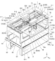
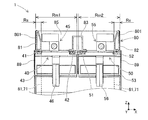
- FIG. 4 is a sectional view taken along line IV-IV in FIG. 3. It is a perspective view which expands and shows the component mounting machine in 2nd embodiment. It is sectional drawing corresponding to FIG. 4 of the component mounting machine in FIG.
- the work machine performs various operations by moving the head.
- the work machine is a component mounting machine
- the component mounting machine is a production apparatus that mounts electronic components at a predetermined mounting position on a circuit board to produce a board product.
- the “circuit board” is simply referred to as “substrate”, and the electronic component is simply referred to as “component”.
- a plurality of component mounting machines 1 are arranged side by side, for example, in the conveyance direction of the substrate Bd, and constitute a production line for producing substrate products.
- the component mounting machine 1 includes a base 2, a substrate transfer device 10, a component supply device 20, two component transfer devices 30, a front column member 60, a rear column member 70, a frame structure 80, a control device 90, and the like. Prepare.
- the horizontal width direction of the component mounting machine 1 (the direction from the upper left to the lower right in FIG. 1) is referred to as the X-axis direction or the left-right direction.
- the horizontal depth direction of the component mounting machine 1 (the direction from the lower left to the upper right in FIG. 1) is referred to as the Y-axis direction or the front-rear direction.
- a vertical direction (vertical direction in FIG. 1) perpendicular to the X-axis and the Y-axis is referred to as a Z-axis direction or a vertical direction.
- the substrate transfer device 10 is installed on the base 2 and is configured by a belt conveyor or the like.
- the substrate transport apparatus 10 sequentially transports the substrate Bd in the transport direction (X-axis direction in the present embodiment).
- the board transfer device 10 positions the board Bd at a predetermined position in the component mounting machine 1. Then, after the mounting process by the component mounting machine 1 is executed, the board transfer device 10 carries the board Bd out of the component mounting machine 1.
- the component supply device 20 is installed on the base 2 and supplies components to be mounted on the board Bd.
- the component supply device 20 includes a plurality of feeders 21 that are set to be replaceable in a plurality of slots arranged side by side in the X-axis direction.
- a carrier tape that stores a large number of parts is wound around a supply reel 22 and loaded into a corresponding feeder 21.
- the feeder 21 feeds and moves the carrier tape, and supplies the components at a supply position located on the front end side of the feeder 21 so that the parts can be collected.
- Each of the two component transfer devices 30 is used for a mounting process in which components supplied by the component supply device 20 are collected and transferred to the substrate Bd.
- each of the two component transfer apparatuses 30 is arranged side by side in the left-right direction of the component mounting machine 1 and supported by the frame structure 80. The detailed configuration of the two component transfer apparatuses 30 will be described later.
- the front column member 60 includes a pair of front columns 61 and a connecting member 62 as shown in FIG.
- the pair of front columns 61 are provided on the left and right of the front portion of the base 2.
- the pair of front columns 61 are connected at their front ends by a connecting member 62 having a portion extending in the left-right direction of the base 2 to constitute an integral gate structure.
- the rear column member 70 is disposed away from the front column member 60 in the front-rear direction of the base 2.
- the rear column member 70 includes a pair of rear columns 71 and a connecting member 72.
- the pair of rear columns 71 are provided on the left and right of the rear portion of the base 2.
- the pair of rear columns 71 are connected to each other by a connecting member 72 having a portion extending in the left-right direction of the base 2 to form an integral portal structure.
- the frame structure 80 is stretched over a pair of front columns 61 and a pair of rear columns 71.
- the frame structure 80 is a strength member that supports the two component transfer devices 30 and improves the rigidity of the entire machine by connecting the front column member 60 and the rear column member 70.
- the detailed configuration of the frame structure 80 will be described later.
- the control device 90 is mainly composed of a CPU, various memories, and a control circuit.
- the control device 90 executes a mounting process for mounting components on the board Bd.
- the above mounting process is executed based on the control program, picks up the components supplied by the component supply device 20, and transfers the components to a predetermined mounting position on the board Bd multiple times. It is a repeated process.
- the control device 90 displays the information output from various sensors provided in the component mounting machine 1 and the result of the recognition process by image processing or the like. input. Then, the control device sends a control signal to the component transfer device 30 based on the control program, information from various sensors, and the results of various recognition processes. Thereby, the position and angle of the component held by the mounting head 35 are controlled.
- control device 90 performs suppression and management of vibration generated with the operation of the mounting head 35 in order to further improve the accuracy of the mounting process. For example, when the mounting head 35 is moved to above the mounting position during the mounting process, the control device 90 determines the movement start position and end position of the mounting head 35, the moving speed, the mass of the moved member, and the like. Based on this, the decay time until the amplitude of the vibration generated with the movement becomes equal to or less than the allowable value is calculated. Then, after waiting for the calculated decay time, the control device 90 lowers the suction nozzle 36 that holds the component and mounts the component on the board Bd at a predetermined mounting position. The accuracy of the mounting process is improved by executing the mounting process with such vibration management.
- the vibration during the execution of the mounting process by the component mounting machine 1 generates a standby time corresponding to the decay time, and thus increases the cycle time required for the mounting process.
- the vibration generated in the component mounting machine 1 has a higher frequency as the rigidity of each member is higher, and a damping time is shorter as the frequency is higher. If the rigidity of each member of the component mounting machine 1 is increased, it can be expected that the standby time due to vibration in the mounting process is shortened. Therefore, in the component mounting machine 1, the front column member 60 and the rear column member 70 provided on the base 2 and the frame structure 80 that connects these and supports the two component transfer devices 30 have high rigidity. It is desirable.
- the component transfer device 30 includes a Y-axis guide device 31, a linear motor 32, an X-axis guide device 33, and a mounting head 35, as shown in FIG.
- the Y-axis guide device 31 moves the mounting head 35 in the front-rear direction (Y-axis direction) of the base 2.
- the Y-axis guide device 31 includes a pair of guide rails 311, four guide blocks 312, and a Y-axis moving body 313.
- the pair of guide rails 311 includes a left rail 311L and a right rail 311R that extend in the front-rear direction of the base 2 and are arranged in parallel.
- Each of the four guide blocks 312 is slidably engaged with the pair of guide rails 311.
- the Y-axis moving body 313 is fixed to the lower part of the four guide blocks 312. Accordingly, the Y-axis moving body 313 is configured to be movable in the front-rear direction of the base 2 while being suspended from the left rail 311L and the right rail 311R.
- the Y-axis guide device 31 is a suspension type that suspends and supports the Y-axis moving body 313 from the pair of guide rails 311 and can ensure a large movable range in the left-right direction.
- the linear motor 32 includes a motor shaft 321, a motor block 322, and a cooling device 323.
- the motor shaft 321 is a stator that is disposed in parallel with the pair of guide rails 311 between the Y-axis directions of the pair of guide rails 311.
- a plurality of ring-shaped permanent magnets are arranged on the motor shaft 321 in the axial direction. The plurality of permanent magnets are arranged so that the directions of the magnetic poles of two adjacent permanent magnets are different from each other.
- the motor block 322 is a mover that is disposed so as to penetrate the motor shaft 321 and moves in the extending direction of the motor shaft 321.
- the motor block 322 has a plurality of coils arranged along the extending direction of the motor shaft 321.
- the cooling device 323 is configured by a heat transfer pipe, a fan, etc. (not shown). The cooling device 323 cools the linear motor 32 by radiating heat generated by driving the linear motor 32 to the outside.
- the Y-axis moving body 313 of the Y-axis guide device 31 is fixed to the lower part of the motor block 322 of the linear motor 32.
- the linear motor 32 generates thrust by supplying power to the coils of the motor block 322.
- the linear motor 32 moves the Y-axis moving body 313 fixed to the motor block 322 to a predetermined position in the Y-axis direction by controlling power feeding to the coil.
- the X-axis guide device 33 moves the mounting head 35 in the left-right direction (X-axis direction) of the base 2.
- the X axis guide device 33 includes an X axis rail 331 and an X axis moving body 332.
- the X-axis rail 331 is disposed on the Y-axis moving body 313 so as to extend in the X-axis direction.
- the X-axis moving body 332 is slidably engaged with the X-axis rail 331.
- the X-axis moving body 332 is moved to a predetermined position in the X-axis direction by a driving device (not shown).
- a driving device for example, a ball screw device or a linear motor can be applied.
- the mounting head 35 is fixed to the X-axis moving body 332 by a clamp (not shown).
- the mounting head 35 has a plurality of suction nozzles 36 that are detachably provided.
- the mounting head 35 supports the respective suction nozzles 36 so as to be rotatable about the R axis parallel to the Z axis and to be movable up and down.
- the suction nozzle 36 is controlled in the elevation position and angle with respect to the mounting head 35 and the supply state of negative pressure.
- the suction nozzle 36 sucks components supplied by the feeder 21 of the component supply device 20 by being supplied with negative pressure.
- the two component transfer devices 30 configured as described above are arranged side by side in the X-axis direction and configured to be operable independently of each other. Specifically, as shown in FIGS. 3 and 4, the mounting heads 35 of the two component transfer apparatuses 30 are mounted on the substrate Bd in the movable ranges Rm ⁇ b> 1 and Rm ⁇ b> 2 that do not overlap each other above the base 2. Each work is done.
- the movable ranges Rm1 and Rm2 are ranges determined by the mechanical configuration of the Y-axis guide device 31 and the X-axis guide device 33, and the mounting head 35 when the mounting head 35 is moved to both the left and right ends and the front and rear ends. It is defined as the enclosing range. 3 and 4 show the movable ranges Rm1 and Rm2 in the X-axis direction of the two component transfer apparatuses 30.
- the left side (upstream side in the conveyance direction of the substrate Bd) of the two component transfer apparatuses 30 is configured as indicated by the corresponding reference numerals in () of FIG. 2.
- the Y-axis guide device 31 is also called a first guide device 40
- the linear motor 32 is also called a first drive device 45
- the mounting head 35 is also called a first head 46.
- the left rail 311L and the right rail 311R constituting the pair of guide rails 311 of the first guide device 40 are also referred to as a first left rail 41 and a first right rail 42.
- the Y-axis guide device 31 constituting the right side (downstream in the conveyance direction of the substrate Bd) of the two component transfer devices 30 is a second guide device 50
- the linear motor 32 is a second drive device 55
- the mounting head 35 is also referred to as a second head 56.
- the left rail 311L and the right rail 311R constituting the pair of guide rails 311 of the second guide device 50 are also referred to as a second left rail 51 and a second right rail 52.
- the frame structure 80 is fixed in a state of being stretched over the front column member 60 and the rear column member 70 that are integral gate-type structures.
- the frame structure 80 has a rectangular shape that surrounds the outer periphery in a top view of the component mounting machine 1.
- the frame structure 80 is formed in a box shape that opens downward and upward, and ensures structural rigidity.
- the frame structure 80 includes a left frame 81, a right frame 82, a center frame 83, a front frame 84, a rear frame 85, and the like, as shown in FIG.
- the left frame 81 extends in the front-rear direction (Y-axis direction) of the base 2 and extends from the left end portion of the front column member 60 to the left end portion of the rear column member 70. Further, as shown in FIG. 4, the left frame 81 has an outer shape with a cross-sectional shape orthogonal to the Y-axis direction that is long in the vertical direction.
- a first left rail 41 of the first guide device 40 is provided below the left frame 81.
- the right frame 82 is formed in a line-symmetric shape with respect to the left frame 81 with the center in the left-right direction of the base 2 being the center line. As shown in FIG. 3, the right frame 82 extends in the front-rear direction (Y-axis direction) of the base 2 and is spanned from the right end portion of the front column member 60 to the right end portion of the rear column member 70. Further, as shown in FIG. 4, the right frame 82 has an outer shape with a cross-sectional shape orthogonal to the Y-axis direction that is long in the vertical direction. A second right rail 52 of the second guide device 50 is provided at the lower part of the right frame 82.
- the center frame 83 is disposed between the left frame 81 and the right frame 82 in the X-axis direction, as shown in FIG.
- the center frame 83 extends in the Y-axis direction and extends from the center portion of the front column member 60 to the center portion of the rear column member 70. Further, as shown in FIG. 4, the center frame 83 is formed in a rectangular shape whose outer shape having a cross-sectional shape orthogonal to the Y-axis direction is long in the vertical direction.
- a first right rail 42 of the first guide device 40 and a second left rail 51 of the second guide device 50 are provided below the center frame 83.
- the front frame 84 and the rear frame 85 extend in the X-axis direction, and an outer shape having a cross-sectional shape orthogonal to the X-axis direction is formed long in the vertical direction.
- the front frame 84 connects the upper portions of the pair of front columns 61 and connects the front ends of the left frame 81, the right frame 82, and the center frame 83.
- the rear frame 85 connects the upper ends of the pair of rear columns 71 and connects the rear ends of the left frame 81, the right frame 82, and the center frame 83.
- the pair of front columns 61 are connected by a connecting member 62 to constitute a front column member 60 that is an integral portal structure.
- the pair of rear columns 71 are connected by a connecting member 72 in the present embodiment to constitute a rear column member 70 that is an integral portal structure. According to such a configuration, the rigidity in the left-right direction of the base 2 can be further increased. Then, by connecting the front column 61 member and the rear column 71 member by the frame structure 80, the component mounting machine 1 has high rigidity as a whole machine and can further reduce the occurrence of vibration.
- the frame structure 80 is formed by connecting a left frame 81, a right frame 82, a front frame 84, and a rear frame 85, which are formed to have substantially the same vertical width. Further, the frame structure 80 has a structure in which a central frame 83 is disposed between the left frame 81 and the right frame 82 to further increase the rigidity. Further, since the cross-sectional shapes of the frames 81 to 86 are long in the vertical direction, the cross-section coefficient is increased and the bending rigidity of the frame structure 80 is increased. As a result, it is possible to increase the frequencies in the X-axis direction and the Y-axis direction of vibrations that occur as the first head 46 and the second head 56 move.
- the frame structure 80 has the rigidity in the X-axis direction required for the frame structure 80 by the front frame 84 and the rear frame 85 (for example, the vibration in the X-axis direction generated by the prescribed operation of the mounting head 35). (Stiffness at which the frequency is equal to or greater than the threshold value).
- the frame structure 80 does not have members for connecting the left frame 81 and the right frame 82 except for the front frame 84 and the rear frame 85. Thereby, weight reduction of the frame structure 80 can be achieved, and the manufacturing cost and installation cost of the frame structure 80 can be reduced.
- the frame structure 80 has a box shape that opens in the vertical direction, and a space for housing the first driving device 45 between the left frame 81 and the central frame 83, and A space for accommodating the second drive device 55 is secured between the right frame 82 and the center frame 83.
- the first drive device 45 is disposed between the left frame 81 and the center frame 83 in the X-axis direction, and both front and rear ends of the base 2 are supported by the front frame 84 and the rear frame 85.
- the second drive device 55 is provided between the right frame 82 and the central frame 83 in the X-axis direction, and the front and rear ends of the base 2 are connected to the front frame 84 and the rear frame. Supported by the frame 85.
- the first drive device 45 and the second drive device 55 which are linear motors 32, have both ends in the Y-axis direction of the respective motor shafts 321 at the front frame 84 and the rear frame 85 as shown in FIG. Supported by Then, the first driving device 45 applies a driving force that moves the first head 46 in the front-rear direction of the base 2 to the first moving body 43. Similarly, the second driving device 55 applies a driving force that moves the second head 56 in the front-rear direction of the base 2 to the second moving body 53.
- the first left rail 41 of the first guide device 40 is provided at the lower portion of the left frame 81.
- the first left rail 41 is a group in which the movable range Rm1 of the first head 46, the pair of front columns 61, and the pair of rear columns 71 are connected to the frame structure 80. It arrange
- FIG. 4 shows in-machine end surfaces of the left front column 61 and the left rear column 71 in broken lines.
- the second right rail 52 of the second guide device 50 is provided at the lower part of the right frame 82.
- the second right rail 52 is a group in which the movable range Rm2 of the second head 56, the pair of front columns 61 and the pair of rear columns 71 are connected to the frame structure 80. It arrange
- FIG. 4 shows in-machine end surfaces of the right front column 61 and the right rear column 71 by broken lines.
- the support range Rs is a range in the X-axis direction in which the frame structure 80 contacts the front column member 60 and the rear column member 70 for connection.
- the support range Rs includes a range in the X-axis direction in which the left frame 81 is directly or indirectly supported by one of the pair of front columns 61 and one of the pair of rear columns 71, and the right frame 82 of the pair of front columns 61. This corresponds to the range indicated by the range in the X-axis direction supported directly or indirectly by the other and the other of the pair of rear columns 71.
- the downward load that the left frame 81 receives from the first left rail 41 is generally transmitted as a buckling load to the left front column 61 and the left rear column 71 existing in the support range Rs.
- the downward load that the right frame 82 receives from the second right rail 52 is generally transmitted as a buckling load to the right front column 61 and the right rear column 71 existing in the support range Rs.
- the first guide device 40 and the second guide device 50 that can generate vibration by the operation are supported by the buckling strength of the front column member 60 and the rear column member 70 via the frame structure 80.
- the component mounting machine 1 is configured to increase the structural rigidity of the entire machine, suppress the occurrence of vibration, and increase the frequency of the generated vibration.
- a first right rail 42 of the first guide device 40 and a second left rail 51 of the second guide device 50 are provided at the lower part of the central frame 83.
- the first right rail 42 is disposed inside the movable range Rm1 of the first head 46 in the X-axis direction, as shown in FIG.
- the second left rail 51 is disposed inside the movable range Rm2 of the second head 56 in the X-axis direction.
- the pair of front columns 61 and the pair of rear columns 71 are arranged such that the side surfaces 611 and 711 on both sides in the left-right direction (X-axis direction) of the base 2 have the same planar shape. Each is formed. As shown in FIG. 1, this is a configuration for enabling installation as close as possible to other adjacent component mounting machines 1 when the component mounting machines 1 constitute a production line. Thereby, the production line including the component mounting machine 1 can be shortened, and the area productivity in the work facility can be improved.
- a pair of left and right connecting plates 89 for connecting the side surfaces (611, 711) is disposed on the side surface 611 of the pair of front columns 61 and the side surface 711 of the pair of rear columns 71.
- the component mounting machine 1 can increase the rigidity in the front-rear direction as a whole machine by using the tensile strength of the connection plate 89. Therefore, the rigidity in the Y-axis direction is particularly increased, and the frequency in the Y-axis direction of the vibration generated with the movement of the first head 46 and the second head 56 can be increased.
- the pair of front columns 61 and the pair of rear columns 71 are connected by the frame structure 80.
- the component mounting machine 1 can improve the rigidity of the entire machine by the structural rigidity of the frame structure 80 while maintaining the external dimensions of the entire machine. Therefore, the frequency of vibration accompanying the movement of the first head 46 and the second head 56 can be increased. As a result, the vibration can be easily suppressed and managed, and the influence of the vibration can be reduced to improve the mounting accuracy.
- the frame structure 80 includes a suspension type first guide device 40 and a second guide device 50, and rails (41, 42, 51, 52) provided below the left frame 81, the right frame 82, and the center frame 83. Support by being provided. Thereby, the component mounting machine 1 can reliably receive the loads of the first guide device 40 and the second guide device 50 by the base 2, the front column member 60, the rear column member 70, and the frame structure 80, Generation of vibrations accompanying the movement of the first head 46 and the second head 56 can be suppressed.
- Second embodiment 2-1 Configuration of Component Mounting Machine 101
- the working machine (component mounting machine 101) of the second embodiment is mainly different in the configuration of the frame structure 80 from the component mounting machine 1 of the first embodiment. Since other common configurations are substantially the same as those in the first embodiment, detailed description thereof is omitted.
- the component mounting machine 101 includes a base 102, a board transfer device 10, a component supply device 20 (not shown in FIG. 5), and one component transfer device 30 (first A guide device 140), a front column member 160, a rear column member 170, a frame structure 180, and a control device 90.
- the component mounting machine 101 of the present embodiment includes one component transfer apparatus 30. Therefore, the component mounting machine 101 and the base 102 are approximately half the width in the X-axis direction compared to the component mounting machine 1 of the first embodiment.
- the component transfer device 30 is the same type as the two component transfer devices 30 in the first embodiment, and includes a first guide device 140, a first drive device 145, a first head 146, and the like.
- the front column member 160 is an integral portal structure formed by connecting a pair of front columns 61 provided on the left and right of the front portion of the base 102 by a connecting member 162 having a portion extending in the X-axis direction. It is.
- the rear column member 170 is an integral portal type formed by connecting a pair of rear columns 71 provided on the left and right of the rear portion of the base 102 by a connecting member 172 having a portion extending in the X-axis direction. It is a structure.
- the frame structure 180 is a strength member that supports one component transfer device 30 and improves the rigidity of the entire machine by connecting the front column member 160 and the rear column member 170. is there.
- the frame structure 180 is configured similarly to the configuration in which the central frame 83 is removed from the frame structure 80 of the first embodiment, and includes a left frame 81, a right frame 82, a front frame 84, a rear frame 85, and the like.
- the left frame 81 is provided with the first left rail 41 of the first guide device 140 at the lower part.
- the right frame 82 is provided with the first right rail 42 of the first guide device 140 at the lower part.
- the front frame 84 connects the pair of front columns 61 to each other and connects the front ends of the left frame 81 and the right frame 82.
- the rear frame 85 connects the pair of rear columns 71 to each other and connects the rear ends of the left frame 81 and the right frame 82.
- the first left rail 41 and the first right rail 42 of the first guide device 140 include a movable range Rm ⁇ b> 1 of the first head 46, a pair of front columns 61, and a pair of rear columns 71. It arrange
- FIG. 6 shows the end surfaces of the pair of front columns 61 and the pair of rear columns 71 on the inner side with broken lines.
- the first driving device 145 is disposed between the left frame 81 and the right frame 82. Further, as shown in FIG. 5, the first driving device 145 is supported by the front frame 84 and the rear frame 85 at both ends in the front-rear direction of the base 102. Specifically, the first drive device 145 that is the linear motor 32 is supported by the front frame 84 and the rear frame 85 at both ends in the Y-axis direction of the motor shaft 321. The first driving device 145 applies a driving force that moves the first head 146 in the front-rear direction of the base 102 to the first moving body 43.
- the downward load that the frame structure 180 receives from the first guide device 140 causes the pair of front columns 61 and the pair of rear columns present in the support range Rs. It is generally transmitted to the column 71 as a buckling load.
- the first guide device 140 that can generate vibrations by the operation thereof is supported by the buckling strength of the front column member 160 and the rear column member 170 via the frame structure 180.
- the component mounting machine 101 is configured to increase the structural rigidity of the entire machine, suppress the occurrence of vibration, and increase the frequency of the generated vibration.
- the pair of front columns 61 and the pair of rear columns 71 are connected by the frame structure 180.
- the component mounting machine 101 can improve the rigidity of the entire machine by the structural rigidity of the frame structure 180 while maintaining the external dimensions of the entire machine. Therefore, the frequency of vibration accompanying the movement of the first head 146 can be increased. As a result, the vibration can be easily suppressed and managed, and the influence of the vibration can be reduced to improve work accuracy.
- the frame structure 180 supports the suspended first guide device 140 by providing the rails (41, 42) below the left frame 81 and the right frame 82. Accordingly, the component mounting machine 101 can reliably receive the load of the first guide device 140 by the base 102, the front column member 160, the rear column member 170, and the frame structure 180, and the movement of the first head 146 The generation of vibrations associated with can be suppressed.
- first and second embodiments 3-1 Configuration of Frame Structure 80
- the frame structures 80 and 180 are configured to be formed in a box shape opened downward and upward.
- the frame structures 80 and 180 may have a shape in which the upper part is covered with a plate or a cover member, for example. If the overall rigidity can be secured, the outer shape of at least a part of the cross-sectional shape of each frame (81, 82, 84, 85) forming the outer shell is formed in a box shape other than the shape elongated in the vertical direction. It is good also as a structure which does not make.
- the front column members 60, 160 are configured as a single gate-type structure in which a pair of front columns 61 are connected by connecting members 62, 162.
- the front column members 60 and 160 do not have the connecting members 62 and 162, and the upper portions may be connected only by the frame structures 80 and 180.
- the rear column members 70 and 170 do not have the connecting members 72 and 172, and the upper portions may be connected only by the frame structures 80 and 180.
- the modes exemplified in the first embodiment and the second embodiment are desirable.
- each of the pair of connection plates 89 connects the side surfaces (611, 711) of the pair of front columns 61 and the pair of rear columns 71.
- the frame structures 80 and 180 are formed such that the side surfaces 801 on both sides in the X-axis direction are the same plane as the respective side surfaces (611 and 711).
- the front column 61 and the pair of rear columns 71 may be connected.
- the component mounting machines 1 and 101 can further increase the longitudinal rigidity of the whole machine by the tensile strength of the pair of connecting plates 89.
- the frequency of the vibration in the front-rear direction accompanying the movement of the mounting head 35 can be increased, so that the vibration can be easily suppressed and managed, and the influence of the vibration can be reduced to improve the mounting accuracy.
- the connection plate 89 may be configured to connect the side surfaces of the bases 2 and 102.
- the first drive devices 45 and 145 and the second drive device 55 are configured to be linear motors 32.
- the first drive devices 45 and 145 and the second drive device 55 drive the first heads 46 and 146 and the second head 56 in the front-rear direction (Y-axis direction) of the base 2 and 102.
- a linear motion device such as a ball screw device may be applied.
- both ends of the screw shaft are supported by the front frame 84 and the rear frame 85.
- the working machine is the component mounting machine 1,101 that produces the board product
- the working machine may be various working machines other than the component mounting machine as long as the working machine is configured to perform various works by moving the head.
- the working machine may be a solder printer that can form a production line together with the component mounting machines 1 and 101, or an inspection device that inspects a circuit board on which the components are mounted.
Landscapes
- Engineering & Computer Science (AREA)
- Manufacturing & Machinery (AREA)
- Microelectronics & Electronic Packaging (AREA)
- Robotics (AREA)
- Mechanical Engineering (AREA)
- Supply And Installment Of Electrical Components (AREA)
- Manipulator (AREA)
Abstract
作業機のフレーム構造体は、第一ガイド装置の第一左レールを下部に設けられた左フレームと、第二ガイド装置の第二右レールを下部に設けられた右フレームと、左フレームと右フレームの間に配置され、第一ガイド装置の第一右レールおよび第二ガイド装置の第二左レールを下部に設けられた中央フレームと、一対の前コラム同士を連結するとともに、左フレーム、右フレーム、および中央フレームの各前端を連結する前フレームと、一対の後コラム同士を連結するとともに、左フレーム、右フレーム、および中央フレームの各後端を連結する後フレームと、を備える。
Description
本発明は、作業機に関するものである。
特許文献1には、ヘッドを移動させて種々の作業を行う作業機として、回路基板に電子部品を装着する部品装着機が開示されている。このような作業機においてヘッドを移動させるガイド装置には、ガイド装置の移動体をレールから吊り下げて支持する懸垂式がある。このような懸垂式のガイド装置には、例えば特許文献1のように、前コラムおよび後コラムに掛け渡された1本のフレームに一対のレールおよび移動体に駆動力を付与する駆動装置を配置する構成がある。
上記のような作業機には、ヘッドの移動に伴う振動の影響を低減して、作業精度の向上の要請がある。また、作業機は、例えば設置面積あたりの生産性の向上を目的として機械全体の小型化が求められている。
本明細書は、機械全体の剛性を向上させて、ヘッドの移動に伴う振動の影響を低減する作業機を提供することを目的とする。
本明細書は、機械全体の剛性を向上させて、ヘッドの移動に伴う振動の影響を低減する作業機を提供することを目的とする。
本明細書は、基台と、前記基台の前部の左右に設けられた一対の前コラムと、前記基台の後部の左右に設けられた一対の後コラムと、前記一対の前コラムおよび前記一対の後コラムに掛け渡されたフレーム構造体と、前記基台の上方における互いに重複しない可動範囲において所定の作業をそれぞれ行う第一ヘッドおよび第二ヘッドと、前記基台の左右方向の中央より左側において前記フレーム構造体に設けられ、前記第一ヘッドを前記基台の前後方向に移動させる第一ガイド装置と、前記基台の左右方向の中央より右側において前記フレーム構造体に設けられ、前記第二ヘッドを前記基台の前後方向に移動させる第二ガイド装置と、を備え、前記第一ガイド装置は、前記基台の前後方向に延伸する平行な第一左レールおよび第一右レールと、前記第一左レールおよび前記第一右レールに吊り下げられた状態で前記基台の前後方向に移動可能に設けられ、前記第一ヘッドを支持する第一移動体と、を有し、前記第二ガイド装置は、前記基台の前後方向に延伸する平行な第二左レールおよび第二右レールと、前記第二左レールおよび前記第二右レールに吊り下げられた状態で前記基台の前後方向に移動可能に設けられ、前記第二ヘッドを支持する第二移動体と、を有し、前記フレーム構造体は、前記第一ガイド装置の前記第一左レールを下部に設けられた左フレームと、前記第二ガイド装置の前記第二右レールを下部に設けられた右フレームと、前記左フレームと前記右フレームの間に配置され、前記第一ガイド装置の前記第一右レールおよび前記第二ガイド装置の前記第二左レールを下部に設けられた中央フレームと、前記一対の前コラム同士を連結するとともに、前記左フレーム、前記右フレーム、および前記中央フレームの各前端を連結する前フレームと、前記一対の後コラム同士を連結するとともに、前記左フレーム、前記右フレーム、および前記中央フレームの各後端を連結する後フレームと、を備える第一の作業機を開示する。
本明細書は、基台と、前記基台の前部の左右に設けられた一対の前コラムと、前記基台の後部の左右に設けられた一対の後コラムと、前記一対の前コラムおよび前記一対の後コラムに掛け渡されたフレーム構造体と、前記基台の上方における可動範囲において所定の作業を行う第一ヘッドと、前記フレーム構造体に設けられ、前記第一ヘッドを前記基台の前後方向に移動させる第一ガイド装置と、を備え、前記第一ガイド装置は、前記基台の前後方向に延伸する平行な第一左レールおよび第一右レールと、前記第一左レールおよび前記第一右レールに吊り下げられた状態で前記基台の前後方向に移動可能に設けられ、前記第一ヘッドを支持する第一移動体と、を有し、前記フレーム構造体は、前記第一ガイド装置の前記第一左レールを下部に設けられた左フレームと、前記第一ガイド装置の前記第一右レールを下部に設けられた右フレームと、前記一対の前コラム同士を連結するとともに、前記左フレームおよび前記右フレームの各前端を連結する前フレームと、前記一対の後コラム同士を連結するとともに、前記左フレームおよび前記右フレームの各後端を連結する後フレームと、を備え、前記第一ガイド装置の前記第一左レールおよび前記第一右レールは、前記第一ヘッドの前記可動範囲と、前記一対の前コラムおよび前記一対の後コラムが前記フレーム構造体と連結される前記基台の左右方向の支持範囲とが重複する範囲内に配置される第二の作業機を開示する。
第一の作業機の構成によると、一対の前コラムおよび一対の後コラムは、左右フレーム、前後フレーム、および中央フレームを備えるフレーム構造体によって連結される。これにより、作業機は、機械全体の外形寸法を維持しつつフレーム構造体の構造的な剛性によって、機械全体としての剛性を向上できる。よって、第一ヘッドおよび第二ヘッドの移動に伴う振動の周波数を高くすることができるので当該振動の抑制や管理が容易となる。結果として、当該振動の影響を低減して作業精度の向上を図ることができる。
また、フレーム構造体は、懸垂式の第一ガイド装置および第二ガイド装置を、左フレーム、右フレームおよび中央フレームの下部に各レールが設けられることによって支持する。これにより、作業機は、第一ガイド装置および第二ガイド装置の荷重を確実に受けることができ、第一ヘッドおよび第二ヘッドの移動に伴う振動の発生を抑制できる。
また、フレーム構造体は、懸垂式の第一ガイド装置および第二ガイド装置を、左フレーム、右フレームおよび中央フレームの下部に各レールが設けられることによって支持する。これにより、作業機は、第一ガイド装置および第二ガイド装置の荷重を確実に受けることができ、第一ヘッドおよび第二ヘッドの移動に伴う振動の発生を抑制できる。
第二の作業機の構成によると、一対の前コラムおよび一対の後コラムは、左右フレームおよび前後フレームを備えるフレーム構造体によって連結される。これにより、作業機は、機械全体の外形寸法を維持しつつフレーム構造体の構造的な剛性によって、機械全体としての剛性を向上できる。よって、第一ヘッドの移動に伴う振動の周波数を高くすることができるので当該振動の抑制や管理が容易となる。結果として、当該振動の影響を低減して作業精度の向上を図ることができる。
また、フレーム構造体は、懸垂式の第一ガイド装置を、左フレームおよび右フレームの下部に各レールが設けられることによって支持する。これにより、作業機は、第一ガイド装置の荷重を確実に受けることができ、第一ヘッドの移動に伴う振動の発生を抑制できる。
また、フレーム構造体は、懸垂式の第一ガイド装置を、左フレームおよび右フレームの下部に各レールが設けられることによって支持する。これにより、作業機は、第一ガイド装置の荷重を確実に受けることができ、第一ヘッドの移動に伴う振動の発生を抑制できる。
1.第一実施形態
以下、作業機を具体化した実施形態について図面を参照して説明する。作業機は、ヘッドを移動させて種々の作業を行う。本実施形態において、作業機が部品装着機である態様を例示する。部品装着機は、回路基板における所定の装着位置に電子部品を装着して基板製品を生産する生産装置である。以下では、「回路基板」を単に「基板」と、電子部品を単に「部品」と称する。
以下、作業機を具体化した実施形態について図面を参照して説明する。作業機は、ヘッドを移動させて種々の作業を行う。本実施形態において、作業機が部品装着機である態様を例示する。部品装着機は、回路基板における所定の装着位置に電子部品を装着して基板製品を生産する生産装置である。以下では、「回路基板」を単に「基板」と、電子部品を単に「部品」と称する。
1-1.部品装着機1の構成
部品装着機1は、図1に示すように、例えば基板Bdの搬送方向に複数並設され、基板製品を生産する生産ラインを構成する。部品装着機1は、基台2、基板搬送装置10、部品供給装置20、2台の部品移載装置30、前コラム部材60、後コラム部材70、フレーム構造体80、および制御装置90などを備える。
部品装着機1は、図1に示すように、例えば基板Bdの搬送方向に複数並設され、基板製品を生産する生産ラインを構成する。部品装着機1は、基台2、基板搬送装置10、部品供給装置20、2台の部品移載装置30、前コラム部材60、後コラム部材70、フレーム構造体80、および制御装置90などを備える。
以下の説明において、部品装着機1の水平幅方向(図1の左上から右下に向かう方向)をX軸方向または左右方向と称する。また、部品装着機1の水平奥行き方向(図1の左下から右上に向かう方向)をY軸方向または前後方向と称する。X軸およびY軸に垂直な鉛直方向(図1の上下方向)をZ軸方向または上下方向と称する。
基板搬送装置10は、基台2に設置され、ベルトコンベアなどにより構成される。基板搬送装置10は、基板Bdを搬送方向(本実施形態においてはX軸方向)へと順次搬送する。基板搬送装置10は、部品装着機1の機内における所定の位置に基板Bdを位置決めする。そして、基板搬送装置10は、部品装着機1による装着処理が実行された後に、基板Bdを部品装着機1の機外に搬出する。
部品供給装置20は、基台2に設置され、基板Bdに装着される部品を供給する。部品供給装置20は、X軸方向に並んで配置された複数のスロットに交換可能にセットされる複数のフィーダ21を有する。多数の部品を収納するキャリアテープは、供給リール22に巻回されて、対応するフィーダ21に装填される。フィーダ21は、キャリアテープを送り移動させ、フィーダ21の先端側に位置する供給位置において部品を採取可能に供給する。
2台の部品移載装置30のそれぞれは、部品供給装置20により供給される部品を採取して基板Bdに移載する装着処理にそれぞれ用いられる。本実施形態において、2台の部品移載装置30のそれぞれは、部品装着機1の左右方向に並んで配置され、フレーム構造体80に支持される。2台の部品移載装置30の詳細構成については後述する。
前コラム部材60は、図2に示すように、一対の前コラム61と、連結部材62とを備える。一対の前コラム61は、基台2の前部の左右に設けられている。一対の前コラム61は、本実施形態において、基台2の左右方向に延伸する部位を有する連結部材62により前端部を連結されて、一体の門型構造体を構成する。
後コラム部材70は、前コラム部材60とは基台2の前後方向に離間して配置される。後コラム部材70は、一対の後コラム71と、連結部材72とを備える。一対の後コラム71は、基台2の後部の左右に設けられている。一対の後コラム71は、本実施形態において、基台2の左右方向に延伸する部位を有する連結部材72により連結されて、一体の門型構造体を構成する。
フレーム構造体80は、一対の前コラム61および一対の後コラム71に掛け渡される。フレーム構造体80は、2台の部品移載装置30を支持するとともに、前コラム部材60および後コラム部材70を連結することによって機械全体の剛性を向上させる強度部材である。フレーム構造体80の詳細構成については後述する。
制御装置90は、主として、CPUや各種メモリ、制御回路により構成される。制御装置90は、基板Bdに部品を装着する装着処理を実行する。上記の装着処理は、制御プログラムに基づいて実行され、部品供給装置20により供給される部品を採取し、部品を基板Bdにおける所定の装着位置に移載するピックアンドプレースサイクルを複数回に亘って繰り返す処理である。
また、制御装置90は、装着処理において、後述する装着ヘッド35の動作を制御する場合に、部品装着機1に複数設けられた各種センサから出力される情報、画像処理などによる認識処理の結果を入力する。そして、制御装置は、制御プログラム、各種センサによる情報、各種の認識処理の結果に基づいて、部品移載装置30へと制御信号を送出する。これにより、装着ヘッド35に保持された部品の位置および角度が制御される。
また、制御装置90は、装着処理の精度をさらに向上させるために、装着ヘッド35の動作に伴って発生する振動の抑制や管理を行う。例えば、制御装置90は、装着処理の実行中に装着ヘッド35を装着位置の上方まで移動させた場合に、装着ヘッド35の移動の開始位置や終了位置、移動速度、移動した部材の質量などに基づいて、当該移動に伴って発生する振動の振幅が許容値以下となるまでの減衰時間を算出する。そして、制御装置90は、算出された減衰時間だけ待機した後に、部品を保持する吸着ノズル36を下降させて、所定の装着位置に基板Bdに部品を装着する。このような振動の管理を伴う装着処理の実行により、装着処理の精度向上が図られている。
また、部品装着機1による装着処理の実行中の振動は、減衰時間に相当する待機時間を発生させることから、装着処理に要するサイクルタイムを延ばす要因となる。ここで、部品装着機1に発生する振動は、各部材の剛性が高くなるほど周波数が高くなり、周波数が高いほど減衰時間が短くなる。部品装着機1の各部材の剛性を高くすると、装着処理における振動に起因する待機時間の短縮を期待できる。よって、部品装着機1には、基台2に設けられる前コラム部材60および後コラム部材70、これらを連結するとともに2台の部品移載装置30を支持するフレーム構造体80が高剛性であることが望ましい。
1-2.部品移載装置30の詳細構成
部品移載装置30は、図2に示すように、Y軸ガイド装置31、リニアモータ32、X軸ガイド装置33、および装着ヘッド35を備える。Y軸ガイド装置31は、装着ヘッド35を基台2の前後方向(Y軸方向)に移動させる。Y軸ガイド装置31は、一対のガイドレール311、4つのガイドブロック312、およびY軸移動体313を有する。一対のガイドレール311は、基台2の前後方向に延伸し平行に配置される左レール311Lおよび右レール311Rにより構成される。
部品移載装置30は、図2に示すように、Y軸ガイド装置31、リニアモータ32、X軸ガイド装置33、および装着ヘッド35を備える。Y軸ガイド装置31は、装着ヘッド35を基台2の前後方向(Y軸方向)に移動させる。Y軸ガイド装置31は、一対のガイドレール311、4つのガイドブロック312、およびY軸移動体313を有する。一対のガイドレール311は、基台2の前後方向に延伸し平行に配置される左レール311Lおよび右レール311Rにより構成される。
4つのガイドブロック312のぞれぞれは、一対のガイドレール311とスライド可能に係合している。Y軸移動体313は、4つのガイドブロック312の下部に固定されている。これにより、Y軸移動体313は、左レール311Lおよび右レール311Rに吊り下げられた状態で基台2の前後方向に移動可能に構成されている。上記のように、Y軸ガイド装置31は、Y軸移動体313を一対のガイドレール311から吊り下げて支持する懸垂式であり、左右方向の可動範囲を大きく確保することができる。
リニアモータ32は、モータ軸321、モータブロック322、および冷却装置323を備える。モータ軸321は、一対のガイドレール311のY軸方向の間において、一対のガイドレール311と平行に配置される固定子である。モータ軸321には、リング状の永久磁石が軸方向に複数配置されている。複数の永久磁石は、隣り合う2つの永久磁石の磁極の向きが互いに異なるように配置されている。
モータブロック322は、モータ軸321に貫通されるように配置され、モータ軸321の延伸方向に移動する可動子である。モータブロック322は、モータ軸321の延伸方向に沿って配置された複数のコイルを有する。冷却装置323は、図示しない伝熱パイプやファンなどにより構成される。冷却装置323は、リニアモータ32の駆動により発生する熱を外部に放熱することにより、リニアモータ32を冷却する。
Y軸ガイド装置31のY軸移動体313は、リニアモータ32のモータブロック322の下部に固定されている。リニアモータ32は、モータブロック322のコイルに給電することによって推力を発生させる。リニアモータ32は、コイルへの給電を制御することによって、モータブロック322に固定されたY軸移動体313をY軸方向の所定の位置まで移動させる。
X軸ガイド装置33は、装着ヘッド35を基台2の左右方向(X軸方向)に移動させる。X軸ガイド装置33は、X軸レール331およびX軸移動体332を有する。X軸レール331は、X軸方向に延伸するようにY軸移動体313に配置される。X軸移動体332は、X軸レール331とスライド可能に係合している。X軸移動体332は、図示しない駆動装置によってX軸方向の所定の位置まで移動される。上記の駆動装置としては、例えばボールねじ装置やリニアモータが適用され得る。
装着ヘッド35は、図示しないクランプによりX軸移動体332に固定される。装着ヘッド35は、着脱可能に設けられる複数の吸着ノズル36を有する。装着ヘッド35は、Z軸と平行なR軸回りに回転可能に、且つ昇降可能にそれぞれの吸着ノズル36を支持する。吸着ノズル36は、装着ヘッド35に対する昇降位置や角度、負圧の供給状態を制御される。吸着ノズル36は、負圧を供給されることにより、部品供給装置20のフィーダ21により供給される部品を吸着する。
上記のように構成される2台の部品移載装置30は、X軸方向に並んで配置され、互いに独立して動作可能に構成される。具体的には、2台の部品移載装置30の各装着ヘッド35は、図3および図4に示すように、基台2の上方における互いに重複しない可動範囲Rm1,Rm2において、基板Bdに部品を装着する作業をそれぞれ行う。ここで、可動範囲Rm1,Rm2は、Y軸ガイド装置31およびX軸ガイド装置33の機械構成によって定まる範囲であって、装着ヘッド35を左右両端および前後両端まで移動させたときの装着ヘッド35を包囲する範囲と定義する。なお、図3および図4は、2台の部品移載装置30のX軸方向の可動範囲Rm1,Rm2を示す。
以下では、説明を簡易にするために、図2の( )内に対応する符号を示すように、2台の部品移載装置30のうち左側(基板Bdの搬送方向の上流側)を構成するY軸ガイド装置31を第一ガイド装置40と、リニアモータ32を第一駆動装置45と、装着ヘッド35を第一ヘッド46とも称する。また、第一ガイド装置40の一対のガイドレール311を構成する左レール311Lおよび右レール311Rを、第一左レール41および第一右レール42とも称する。
さらに、2台の部品移載装置30にうち右側(基板Bdの搬送方向の下流側)を構成するY軸ガイド装置31を第二ガイド装置50と、リニアモータ32を第二駆動装置55と、装着ヘッド35を第二ヘッド56とも称する。また、第二ガイド装置50の一対のガイドレール311を構成する左レール311Lおよび右レール311Rを、第二左レール51および第二右レール52とも称する。
1-3.フレーム構造体80の詳細構成
フレーム構造体80は、本実施形態において、一体の門型構造体である前コラム部材60および後コラム部材70に掛け渡された状態で固定される。本実施形態において、フレーム構造体80は、図3に示すように、部品装着機1の上面視において外周を囲う矩形状をなす。フレーム構造体80は、下方および上方に開口した箱状に形成され、構造的な剛性の確保を図られている。
フレーム構造体80は、本実施形態において、一体の門型構造体である前コラム部材60および後コラム部材70に掛け渡された状態で固定される。本実施形態において、フレーム構造体80は、図3に示すように、部品装着機1の上面視において外周を囲う矩形状をなす。フレーム構造体80は、下方および上方に開口した箱状に形成され、構造的な剛性の確保を図られている。
フレーム構造体80は、図3に示すように、左フレーム81、右フレーム82、中央フレーム83、前フレーム84、および後フレーム85などを備える。左フレーム81は、基台2の前後方向(Y軸方向)に延伸し、前コラム部材60の左端部から後コラム部材70の左端部に掛け渡される。また、左フレーム81は、図4に示すように、Y軸方向に直交する断面形状の外形が上下方向に長く形成される。左フレーム81の下部には、第一ガイド装置40の第一左レール41が設けられる。
右フレーム82は、基台2の左右方向の中央を中心線として、左フレーム81の線対称形状に形成される。右フレーム82は、図3に示すように、基台2の前後方向(Y軸方向)に延伸し、前コラム部材60の右端部から後コラム部材70の右端部に掛け渡される。また、右フレーム82は、図4に示すように、Y軸方向に直交する断面形状の外形が上下方向に長く形成される。右フレーム82の下部には、第二ガイド装置50の第二右レール52が設けられる。
中央フレーム83は、図3に示すように、X軸方向における左フレーム81と右フレーム82の間に配置される。中央フレーム83は、Y軸方向に延伸し、前コラム部材60の中央部から後コラム部材70の中央部に掛け渡される。また、中央フレーム83は、図4に示すように、Y軸方向に直交する断面形状の外形が上下方向に長い矩形に形成される。中央フレーム83の下部には、第一ガイド装置40の第一右レール42および第二ガイド装置50の第二左レール51が設けられる。
前フレーム84および後フレーム85は、図3に示すように、X軸方向に延伸し、X軸方向に直交する断面形状の外形が上下方向に長く形成される。前フレーム84は、一対の前コラム61の上部同士を連結するとともに、左フレーム81、右フレーム82、および中央フレーム83の各前端を連結する。後フレーム85は、一対の後コラム71の上部同士を連結するとともに、左フレーム81、右フレーム82、および中央フレーム83の各後端を連結する。
ここで、一対の前コラム61は、本実施形態において、連結部材62により連結されて、一体の門型構造体である前コラム部材60を構成する。また、一対の後コラム71は、本実施形態において連結部材72により連結されて、一体の門型構造体である後コラム部材70を構成する。このような構成によると、基台2の左右方向の剛性をより高くすることができる。そして、これらの前コラム61部材および後コラム71部材がフレーム構造体80により連結されることによって、部品装着機1は、機械全体としての剛性が高くなり、振動の発生をより低減できる。
本実施形態において、フレーム構造体80は、上下方向幅がほぼ同一に形成される左フレーム81、右フレーム82、前フレーム84、および後フレーム85が連結されて外郭を形成される。また、フレーム構造体80は、左フレーム81と右フレーム82との間に中央フレーム83が配置されて、剛性をさらに高くする構造となっている。また、各フレーム81~86の断面形状が上下方向に長く形成することにより断面係数を高くして、フレーム構造体80の曲げ剛性が高められている。これにより、第一ヘッド46および第二ヘッド56の移動に伴い発生する振動のX軸方向およびY軸方向の周波数を高くすることができる。
また、本実施形態において、フレーム構造体80は、前フレーム84および後フレーム85によりフレーム構造体80に要求されるX軸方向の剛性(例えば装着ヘッド35の規定動作により発生するX軸方向の振動の周波数が閾値以上となる剛性)を確保する。これにより、フレーム構造体80は、前フレーム84および後フレーム85を除いて、左フレーム81および右フレーム82を連結する部材を有しない。これにより、フレーム構造体80の軽量化を図ることができ、またフレーム構造体80の製造コストや設置コストを低減できる。
また、上記のような構成により、結果として、フレーム構造体80は、上下方向に開口する箱状をなし、左フレーム81と中央フレーム83との間に第一駆動装置45を収容するスペース、および右フレーム82と中央フレーム83との間に第二駆動装置55を収容するスペースを確保している。詳細には、第一駆動装置45は、X軸方向における左フレーム81と中央フレーム83との間に配置され、基台2の前後方向の両端部を前フレーム84および後フレーム85に支持される。同様に、第二駆動装置55は、X軸方向における第二駆動装置55は、右フレーム82と中央フレーム83との間に設けられ、基台2の前後方向の両端部を前フレーム84および後フレーム85に支持される。
具体的には、リニアモータ32である第一駆動装置45および第二駆動装置55は、図3に示すように、それぞれのモータ軸321のY軸方向の両端部を前フレーム84および後フレーム85に支持される。そして、第一駆動装置45は、第一ヘッド46を基台2の前後方向に移動させる駆動力を第一移動体43に付与する。同様に、第二駆動装置55は、第二ヘッド56を基台2の前後方向に移動させる駆動力を第二移動体53に付与する。
また、上記のように、左フレーム81の下部には、第一ガイド装置40の第一左レール41が設けられる。本実施形態において、第一左レール41は、図4に示すように、第一ヘッド46の可動範囲Rm1と、一対の前コラム61および一対の後コラム71がフレーム構造体80と連結される基台2の左右方向の支持範囲Rsとが重複する範囲内に配置される。図4は、左側の前コラム61および左側の後コラム71の機内側の端面を破線にて示す。
また、右フレーム82の下部には、第二ガイド装置50の第二右レール52が設けられる。本実施形態において、第二右レール52は、図4に示すように、第二ヘッド56の可動範囲Rm2と、一対の前コラム61および一対の後コラム71がフレーム構造体80と連結される基台2の左右方向の支持範囲Rsとが重複する範囲内に配置される。図4は、右側の前コラム61および右側の後コラム71の機内側の端面を破線にて示す。
ここで、上記の支持範囲Rsは、前コラム部材60および後コラム部材70に対してフレーム構造体80が連結のために接触するX軸方向の範囲である。支持範囲Rsは、左フレーム81が一対の前コラム61の一方および一対の後コラム71の一方に直接または間接的に支持されるX軸方向の範囲と、右フレーム82が一対の前コラム61の他方および一対の後コラム71の他方に直接または間接的に支持されるX軸方向の範囲と、によって示される範囲に相当する。
このような構成により、左フレーム81が第一左レール41から受ける下方への荷重は、支持範囲Rsに存在する左側の前コラム61および左側の後コラム71に座屈荷重として概ね伝達される。同様に、右フレーム82が第二右レール52から受ける下方への荷重は支持範囲Rsに存在する右側の前コラム61および右側の後コラム71に座屈荷重として概ね伝達される。
これにより、その動作によって振動を発生し得る第一ガイド装置40および第二ガイド装置50は、フレーム構造体80を介して前コラム部材60および後コラム部材70の座屈強度によって支持される。結果として、部品装着機1は、機械全体としての構造的な剛性を高めて、振動の発生を抑制するとともに、発生した振動の周波数を高くするように構成されている。
また、中央フレーム83の下部には、第一ガイド装置40の第一右レール42および第二ガイド装置50の第二左レール51が設けられる。本実施形態において、第一右レール42は、図4に示すように、X軸方向における第一ヘッド46の可動範囲Rm1の内側に配置される。同様に、第二左レール51は、X軸方向における第二ヘッド56の可動範囲Rm2の内側に配置される。
ここで、一対の前コラム61、および一対の後コラム71は、図2に示すように、基台2の左右方向(X軸方向)両側の側面611,711が同一の平面状をなすようにそれぞれ形成される。これは、図1に示すように、部品装着機1が生産ラインを構成する場合に、隣り合う他の部品装着機1となるべく近接した設置を可能とするための構成である。これにより、部品装着機1を含む生産ラインを短縮して、作業施設における面積生産性を向上できる。
さらに、一対の前コラム61の側面611および一対の後コラム71の側面711には、図1に示すように、各側面(611,711)同士を連結する左右一対の連結プレート89が配置される。このような構成により、連結プレート89の引っ張り強度を利用して、部品装着機1は、機械全体として前後方向の剛性を高くすることができる。よって、特にY軸方向の剛性が高まり、第一ヘッド46および第二ヘッド56の移動に伴い発生する振動のY軸方向の周波数を高くすることができる。
1-4.第一実施形態の構成による効果
上記のような部品装着機1の構成によると、一対の前コラム61および一対の後コラム71は、フレーム構造体80によって連結される。これにより、部品装着機1は、機械全体の外形寸法を維持しつつフレーム構造体80の構造的な剛性によって、機械全体としての剛性を向上できる。よって、第一ヘッド46および第二ヘッド56の移動に伴う振動の周波数を高くすることができる。結果として、当該振動の抑制や管理が容易となり、当該振動の影響を低減して装着精度の向上を図ることができる。
上記のような部品装着機1の構成によると、一対の前コラム61および一対の後コラム71は、フレーム構造体80によって連結される。これにより、部品装着機1は、機械全体の外形寸法を維持しつつフレーム構造体80の構造的な剛性によって、機械全体としての剛性を向上できる。よって、第一ヘッド46および第二ヘッド56の移動に伴う振動の周波数を高くすることができる。結果として、当該振動の抑制や管理が容易となり、当該振動の影響を低減して装着精度の向上を図ることができる。
また、フレーム構造体80は、懸垂式の第一ガイド装置40および第二ガイド装置50を、左フレーム81、右フレーム82および中央フレーム83の下部に各レール(41,42,51,52)が設けられることによって支持する。これにより、部品装着機1は、基台2、前コラム部材60、後コラム部材70、およびフレーム構造体80によって第一ガイド装置40および第二ガイド装置50の荷重を確実に受けることができ、第一ヘッド46および第二ヘッド56の移動に伴う振動の発生を抑制できる。
2.第二実施形態
2-1.部品装着機101の構成
第二実施形態の作業機(部品装着機101)は、主として、第一実施形態の部品装着機1に対してフレーム構造体80の構成が相違する。その他の共通する構成については、第一実施形態と実質的に同一であるため、詳細な説明を省略する。具体的には、部品装着機101は、図5に示すように、基台102、基板搬送装置10、部品供給装置20(図5にて省略)、1台の部品移載装置30(第一ガイド装置140)、前コラム部材160、後コラム部材170、フレーム構造体180、および制御装置90などを備える。
2-1.部品装着機101の構成
第二実施形態の作業機(部品装着機101)は、主として、第一実施形態の部品装着機1に対してフレーム構造体80の構成が相違する。その他の共通する構成については、第一実施形態と実質的に同一であるため、詳細な説明を省略する。具体的には、部品装着機101は、図5に示すように、基台102、基板搬送装置10、部品供給装置20(図5にて省略)、1台の部品移載装置30(第一ガイド装置140)、前コラム部材160、後コラム部材170、フレーム構造体180、および制御装置90などを備える。
第一実施形態の部品装着機1が2台の部品移載装置30を備える構成に対して、本実施形態の部品装着機101は、1台の部品移載装置30を備える。そのため、部品装着機101および基台102は、X軸方向の幅が第一実施形態の部品装着機1と比較して概ね半分となっている。上記の部品移載装置30は、第一実施形態における2台の部品移載装置30と同型であり、第一ガイド装置140、第一駆動装置145、および第一ヘッド146などを備える。
前コラム部材160は、基台102の前部の左右に設けられた一対の前コラム61を、X軸方向に延伸する部位を有する連結部材162により連結されて構成される一体の門型構造体である。同様に、後コラム部材170は、基台102の後部の左右に設けられた一対の後コラム71を、X軸方向に延伸する部位を有する連結部材172により連結されて構成される一体の門型構造体である。
2-2.フレーム構造体180の詳細構成
フレーム構造体180は、1台の部品移載装置30を支持するとともに、前コラム部材160および後コラム部材170を連結することによって機械全体の剛性を向上させる強度部材である。フレーム構造体180は、第一実施形態のフレーム構造体80から中央フレーム83を除いた構成と同様に構成され、左フレーム81、右フレーム82、前フレーム84、および後フレーム85などを備える。
フレーム構造体180は、1台の部品移載装置30を支持するとともに、前コラム部材160および後コラム部材170を連結することによって機械全体の剛性を向上させる強度部材である。フレーム構造体180は、第一実施形態のフレーム構造体80から中央フレーム83を除いた構成と同様に構成され、左フレーム81、右フレーム82、前フレーム84、および後フレーム85などを備える。
左フレーム81は、図6に示すように、第一ガイド装置140の第一左レール41を下部に設けられる。右フレーム82は、第一ガイド装置140の第一右レール42を下部に設けられる。前フレーム84は、第一実施形態と同様に、一対の前コラム61同士を連結するとともに、左フレーム81および右フレーム82の各前端を連結する。後フレーム85は、一対の後コラム71同士を連結するとともに、左フレーム81および右フレーム82の各後端を連結する。
第一ガイド装置140の第一左レール41および第一右レール42は、図6に示すように、第一ヘッド46の可動範囲Rm1と、一対の前コラム61および一対の後コラム71がフレーム構造体180と連結される基台102の左右方向の支持範囲Rsとが重複する範囲内に配置される。図6は、一対の前コラム61および一対の後コラム71の機内側の端面を破線にて示す。
また、第一駆動装置145は、左フレーム81と右フレーム82との間に配置される。また、第一駆動装置145は、図5に示すように、基台102の前後方向の両端部を前フレーム84および後フレーム85に支持される。具体的には、リニアモータ32である第一駆動装置145は、モータ軸321のY軸方向の両端部を前フレーム84および後フレーム85に支持される。第一駆動装置145は、第一ヘッド146を基台102の前後方向に移動させる駆動力を第一移動体43に付与する。
このような構成により、第一実施形態の構成と同様に、フレーム構造体180が第一ガイド装置140から受ける下方への荷重は、支持範囲Rsに存在する一対の前コラム61のおよび一対の後コラム71に座屈荷重として概ね伝達される。これにより、その動作によって振動を発生し得る第一ガイド装置140は、フレーム構造体180を介して前コラム部材160および後コラム部材170の座屈強度によって支持される。結果として、部品装着機101は、機械全体としての構造的な剛性を高めて、振動の発生を抑制するとともに、発生した振動の周波数を高くするように構成されている。
2-3.第二実施形態の構成による効果
上記のような部品装着機101の構成によると、一対の前コラム61および一対の後コラム71は、フレーム構造体180によって連結される。これにより、部品装着機101は、機械全体の外形寸法を維持しつつフレーム構造体180の構造的な剛性によって、機械全体としての剛性を向上できる。よって、第一ヘッド146の移動に伴う振動の周波数を高くすることができる。結果として、当該振動の抑制や管理が容易となり、当該振動の影響を低減して作業精度の向上を図ることができる。
上記のような部品装着機101の構成によると、一対の前コラム61および一対の後コラム71は、フレーム構造体180によって連結される。これにより、部品装着機101は、機械全体の外形寸法を維持しつつフレーム構造体180の構造的な剛性によって、機械全体としての剛性を向上できる。よって、第一ヘッド146の移動に伴う振動の周波数を高くすることができる。結果として、当該振動の抑制や管理が容易となり、当該振動の影響を低減して作業精度の向上を図ることができる。
また、フレーム構造体180は、懸垂式の第一ガイド装置140を、左フレーム81および右フレーム82の下部に各レール(41,42)が設けられることによって支持する。これにより、部品装着機101は、基台102、前コラム部材160、後コラム部材170、およびフレーム構造体180によって第一ガイド装置140の荷重を確実に受けることができ、第一ヘッド146の移動に伴う振動の発生を抑制できる。
3.第一、第二実施形態の変形態様
3-1.フレーム構造体80の構成
第一実施形態および第二実施形態において、フレーム構造体80,180は、下方および上方に開口した箱状に形成される構成とした。これに対して、フレーム構造体80,180は、例えば上方がプレートやカバー部材により覆われた形状としてもよい。また、全体としての剛性が確保できるのであれば、外郭を形成する各フレーム(81,82,84,85)の少なくとも一部の断面形状の外形が上下方向に長い形状以外に形成され、箱状をなさない構成としてもよい。
3-1.フレーム構造体80の構成
第一実施形態および第二実施形態において、フレーム構造体80,180は、下方および上方に開口した箱状に形成される構成とした。これに対して、フレーム構造体80,180は、例えば上方がプレートやカバー部材により覆われた形状としてもよい。また、全体としての剛性が確保できるのであれば、外郭を形成する各フレーム(81,82,84,85)の少なくとも一部の断面形状の外形が上下方向に長い形状以外に形成され、箱状をなさない構成としてもよい。
また、第一実施形態および第二実施形態において、前コラム部材60,160は、一対の前コラム61が連結部材62,162により連結されて一体の門型構造体である構成とした。これに対して、前コラム部材60,160は、連結部材62,162を有さず、上部をフレーム構造体80,180のみによって連結される構成としてもよい。同様に、後コラム部材70,170は、連結部材72,172を有さず、上部をフレーム構造体80,180のみによって連結される構成としてもよい。但し、剛性を確保するとともに部品点数を削減する観点からは、第一実施形態および第二実施形態にて例示した態様が望ましい。
3-2.連結プレート89の構成
第一、第二実施形態において、一対の連結プレート89のそれぞれは、一対の前コラム61および一対の後コラム71の各側面(611,711)同士を連結するものとした。これに対して、フレーム構造体80,180は、X軸方向両側の側面801が上記の各側面(611,711)と同一の平面状をなすようにそれぞれ形成され、一対の連結プレート89により一対の前コラム61および一対の後コラム71と連結されてもよい。
第一、第二実施形態において、一対の連結プレート89のそれぞれは、一対の前コラム61および一対の後コラム71の各側面(611,711)同士を連結するものとした。これに対して、フレーム構造体80,180は、X軸方向両側の側面801が上記の各側面(611,711)と同一の平面状をなすようにそれぞれ形成され、一対の連結プレート89により一対の前コラム61および一対の後コラム71と連結されてもよい。
このような構成によると、部品装着機1,101は、一対の連結プレート89の引っ張り強度によって、機械全体として前後方向の剛性をさらに高くすることができる。結果として、装着ヘッド35の移動に伴う前後方向の振動の周波数を高くすることができるので、当該振動の抑制や管理が容易となり、当該振動の影響を低減して装着精度の向上を図ることができる。さらに、連結プレート89は、基台2,102の側面を連結する構成としてもよい。
3-3.作業機の基本構成
第一実施形態および第二実施形態において、第一駆動装置45,145および第二駆動装置55は、リニアモータ32である構成とした。これに対して、第一駆動装置45,145および第二駆動装置55は、第一ヘッド46,146および第二ヘッド56を基台2,102の前後方向(Y軸方向)に移動させる駆動力を第一移動体43および第二移動体53に付与可能であれば、ボールねじ装置などの直動装置を適用してもよい。例えば、第一駆動装置45,145および第二駆動装置55がボールねじ装置である場合には、ねじ軸の両端部が前フレーム84および後フレーム85に支持される。
第一実施形態および第二実施形態において、第一駆動装置45,145および第二駆動装置55は、リニアモータ32である構成とした。これに対して、第一駆動装置45,145および第二駆動装置55は、第一ヘッド46,146および第二ヘッド56を基台2,102の前後方向(Y軸方向)に移動させる駆動力を第一移動体43および第二移動体53に付与可能であれば、ボールねじ装置などの直動装置を適用してもよい。例えば、第一駆動装置45,145および第二駆動装置55がボールねじ装置である場合には、ねじ軸の両端部が前フレーム84および後フレーム85に支持される。
第一実施形態および第二実施形態において、作業機が基板製品を生産する部品装着機1,101である態様を例示して説明した。これに対して、作業機は、ヘッドを移動させて種々の作業を行う構成であれば、部品装着機以外の各種作業機であってもよい。具体的には、作業機は、部品装着機1,101とともに生産ラインを構成し得るはんだ印刷機、部品を装着された回路基板を検査する検査装置であってもよい。
1,101:部品装着機、 2,102:基台、 10:基板搬送装置、 20:部品供給装置、 30:部品移載装置、 31(40,50,140):Y軸ガイド装置(第一ガイド装置、第二ガイド装置)、 311:ガイドレール、 311L(41,51):左レール(第一左レール、第二左レール)、 311R(42,52):右レール(第一右レール、第二右レール)、 312:ガイドブロック、 313(43,53):Y軸移動体(第一移動体、第二移動体)、 32(45,55,145):リニアモータ(第一駆動装置、第二駆動装置)、 35(46,56,146):装着ヘッド(第一ヘッド、第二ヘッド)、 60,160:前コラム部材、 61:(一対の)前コラム、 611:側面、 62,162:連結部材、 70,170:後コラム部材、 71:(一対の)後コラム、 711:側面、 72,172:連結部材、 80,180:フレーム構造体、 81:左フレーム、 82:右フレーム、 83:中央フレーム、 84:前フレーム、 85:後フレーム、 801:側面、 89:(一対の)連結プレート、 Rm1:(第一装着ヘッドの)可動範囲、 Rm2:(第二装着ヘッドの)可動範囲、 Rs:支持範囲、 Bd:基板(回路基板)
Claims (14)
- 基台と、
前記基台の前部の左右に設けられた一対の前コラムと、
前記基台の後部の左右に設けられた一対の後コラムと、
前記一対の前コラムおよび前記一対の後コラムに掛け渡されたフレーム構造体と、
前記基台の上方における互いに重複しない可動範囲において所定の作業をそれぞれ行う第一ヘッドおよび第二ヘッドと、
前記基台の左右方向の中央より左側において前記フレーム構造体に設けられ、前記第一ヘッドを前記基台の前後方向に移動させる第一ガイド装置と、
前記基台の左右方向の中央より右側において前記フレーム構造体に設けられ、前記第二ヘッドを前記基台の前後方向に移動させる第二ガイド装置と、を備え、
前記第一ガイド装置は、
前記基台の前後方向に延伸する平行な第一左レールおよび第一右レールと、
前記第一左レールおよび前記第一右レールに吊り下げられた状態で前記基台の前後方向に移動可能に設けられ、前記第一ヘッドを支持する第一移動体と、を有し、
前記第二ガイド装置は、
前記基台の前後方向に延伸する平行な第二左レールおよび第二右レールと、
前記第二左レールおよび前記第二右レールに吊り下げられた状態で前記基台の前後方向に移動可能に設けられ、前記第二ヘッドを支持する第二移動体と、を有し、
前記フレーム構造体は、
前記第一ガイド装置の前記第一左レールを下部に設けられた左フレームと、
前記第二ガイド装置の前記第二右レールを下部に設けられた右フレームと、
前記左フレームと前記右フレームの間に配置され、前記第一ガイド装置の前記第一右レールおよび前記第二ガイド装置の前記第二左レールを下部に設けられた中央フレームと、
前記一対の前コラム同士を連結するとともに、前記左フレーム、前記右フレーム、および前記中央フレームの各前端を連結する前フレームと、
前記一対の後コラム同士を連結するとともに、前記左フレーム、前記右フレーム、および前記中央フレームの各後端を連結する後フレームと、
を備える作業機。 - 前記第一ガイド装置の前記第一左レールは、前記第一ヘッドの前記可動範囲と、前記一対の前コラムおよび前記一対の後コラムが前記フレーム構造体と連結される前記基台の左右方向の支持範囲とが重複する範囲内に配置され、
前記第二ガイド装置の前記第二右レールは、前記第二ヘッドの前記可動範囲と、前記一対の前コラムおよび前記一対の後コラムが前記フレーム構造体と連結される前記基台の左右方向の支持範囲とが重複する範囲内に配置される、請求項1に記載の作業機。 - 前記中央フレームは、前記基台の前後方向に直交する断面形状の外形が上下方向に長い矩形に形成される、請求項1または2に記載の作業機。
- 前記作業機は、
前記左フレームと前記中央フレームとの間に配置され、前記基台の前後方向の両端部を前記前フレームおよび前記後フレームに支持され、前記第一ヘッドを前記基台の前後方向に移動させる駆動力を前記第一移動体に付与する第一駆動装置と、
前記右フレームと前記中央フレームとの間に設けられ、前記基台の前後方向の両端部を前記前フレームおよび前記後フレームに支持され、前記第二ヘッドを前記基台の前後方向に移動させる駆動力を前記第二移動体に付与する第二駆動装置と、をさらに備える、請求項1-3の何れか一項に記載の作業機。 - 基台と、
前記基台の前部の左右に設けられた一対の前コラムと、
前記基台の後部の左右に設けられた一対の後コラムと、
前記一対の前コラムおよび前記一対の後コラムに掛け渡されたフレーム構造体と、
前記基台の上方における可動範囲において所定の作業を行う第一ヘッドと、
前記フレーム構造体に設けられ、前記第一ヘッドを前記基台の前後方向に移動させる第一ガイド装置と、を備え、
前記第一ガイド装置は、
前記基台の前後方向に延伸する平行な第一左レールおよび第一右レールと、
前記第一左レールおよび前記第一右レールに吊り下げられた状態で前記基台の前後方向に移動可能に設けられ、前記第一ヘッドを支持する第一移動体と、を有し、
前記フレーム構造体は、
前記第一ガイド装置の前記第一左レールを下部に設けられた左フレームと、
前記第一ガイド装置の前記第一右レールを下部に設けられた右フレームと、
前記一対の前コラム同士を連結するとともに、前記左フレームおよび前記右フレームの各前端を連結する前フレームと、
前記一対の後コラム同士を連結するとともに、前記左フレームおよび前記右フレームの各後端を連結する後フレームと、を備え、
前記第一ガイド装置の前記第一左レールおよび前記第一右レールは、前記第一ヘッドの前記可動範囲と、前記一対の前コラムおよび前記一対の後コラムが前記フレーム構造体と連結される前記基台の左右方向の支持範囲とが重複する範囲内に配置される作業機。 - 前記作業機は、
前記左フレームと前記右フレームとの間に配置され、前記基台の前後方向の両端部を前記前フレームおよび前記後フレームに支持され、前記第一ヘッドを前記基台の前後方向に移動させる駆動力を前記第一移動体に付与する第一駆動装置をさらに備える、請求項5に記載の作業機。 - 前記一対の前コラム、前記一対の後コラム、および前記フレーム構造体は、前記基台の左右方向両側の側面が同一の平面状をなすようにそれぞれ形成される、請求項1-6の何れか一項に記載の作業機。
- 前記作業機は、前記一対の前コラムおよび前記一対の後コラムの各前記側面同士を連結する左右一対の連結プレートをさらに備える、請求項1-7の何れか一項に記載の作業機。
- 前記一対の連結プレートのそれぞれは、前記一対の前コラム、前記一対の後コラム、および前記フレーム構造体の各前記側面同士を連結する、請求項8に記載の作業機。
- 前記左フレームおよび前記右フレームは、前記基台の前後方向に直交する断面形状の外形が上下方向に長く形成される、請求項1-9の何れか一項に記載の作業機。
- 前記前フレームおよび前記後フレームは、前記基台の前後方向に直交する断面形状の外形が上下方向に長く形成され、
前記フレーム構造体は、少なくとも下方に開口した箱状に形成される、請求項10に記載の作業機。 - 前記一対の前コラムおよび前記一対の後コラムのそれぞれは、前記基台の左右方向に延伸する連結部材により連結されて一体の門型構造体を構成する、請求項1-11の何れか一項に記載の作業機。
- 前記フレーム構造体は、前記前フレームおよび前記後フレームを除いて、前記左フレームおよび前記右フレームを連結する部材を有しない、請求項1-12の何れか一項に記載の作業機。
- 前記第一ヘッドは、回路基板に電子部品を装着する作業を行う装着ヘッドであり、
前記作業機は、前記第一ヘッドを用いて基板製品を生産する部品装着機である、請求項1-13の何れか一項に記載の作業機。
Priority Applications (5)
| Application Number | Priority Date | Filing Date | Title |
|---|---|---|---|
| JP2018562765A JP6761485B2 (ja) | 2017-01-17 | 2017-01-17 | 作業機 |
| CN201780083478.7A CN110199586B (zh) | 2017-01-17 | 2017-01-17 | 作业机 |
| EP17892443.7A EP3573441B1 (en) | 2017-01-17 | 2017-01-17 | Work machine |
| US16/476,136 US11134596B2 (en) | 2017-01-17 | 2017-01-17 | Work machine |
| PCT/JP2017/001414 WO2018134893A1 (ja) | 2017-01-17 | 2017-01-17 | 作業機 |
Applications Claiming Priority (1)
| Application Number | Priority Date | Filing Date | Title |
|---|---|---|---|
| PCT/JP2017/001414 WO2018134893A1 (ja) | 2017-01-17 | 2017-01-17 | 作業機 |
Publications (1)
| Publication Number | Publication Date |
|---|---|
| WO2018134893A1 true WO2018134893A1 (ja) | 2018-07-26 |
Family
ID=62907933
Family Applications (1)
| Application Number | Title | Priority Date | Filing Date |
|---|---|---|---|
| PCT/JP2017/001414 Ceased WO2018134893A1 (ja) | 2017-01-17 | 2017-01-17 | 作業機 |
Country Status (5)
| Country | Link |
|---|---|
| US (1) | US11134596B2 (ja) |
| EP (1) | EP3573441B1 (ja) |
| JP (1) | JP6761485B2 (ja) |
| CN (1) | CN110199586B (ja) |
| WO (1) | WO2018134893A1 (ja) |
Cited By (1)
| Publication number | Priority date | Publication date | Assignee | Title |
|---|---|---|---|---|
| JP2021053650A (ja) * | 2019-09-27 | 2021-04-08 | ブラザー工業株式会社 | レーザ加工装置 |
Families Citing this family (2)
| Publication number | Priority date | Publication date | Assignee | Title |
|---|---|---|---|---|
| CN110282341A (zh) * | 2019-06-25 | 2019-09-27 | 英业达科技有限公司 | 取放装置 |
| CN111642126B (zh) * | 2020-05-25 | 2021-04-09 | 深圳市琦轩实创科技有限公司 | 一种用于电子类产品生产的贴片设备 |
Citations (7)
| Publication number | Priority date | Publication date | Assignee | Title |
|---|---|---|---|---|
| JPH09150330A (ja) * | 1995-11-27 | 1997-06-10 | Sony Corp | 表面実装機用ロボットにおけるヘッド搭載部移動機構 |
| JP2000069781A (ja) * | 1998-08-20 | 2000-03-03 | Yamaha Motor Co Ltd | 直線方向駆動機構の制御装置 |
| JP2002534783A (ja) * | 1998-12-29 | 2002-10-15 | コーニンクレッカ フィリップス エレクトロニクス エヌ ヴィ | 素子配置機械 |
| JP2005064222A (ja) * | 2003-08-12 | 2005-03-10 | Matsushita Electric Ind Co Ltd | 部品実装機用架台及び部品実装機 |
| JP2009272555A (ja) * | 2008-05-09 | 2009-11-19 | Yamaha Motor Co Ltd | 基板処理装置 |
| JP2012044128A (ja) | 2010-08-18 | 2012-03-01 | Fuji Mach Mfg Co Ltd | 電子回路部品装着機および電子回路部品装着システム |
| JP2015015410A (ja) * | 2013-07-08 | 2015-01-22 | パナソニックIpマネジメント株式会社 | 部品実装装置 |
Family Cites Families (5)
| Publication number | Priority date | Publication date | Assignee | Title |
|---|---|---|---|---|
| JP3255062B2 (ja) * | 1997-01-17 | 2002-02-12 | 松下電器産業株式会社 | 電子部品装着装置 |
| US6976304B2 (en) * | 2001-07-27 | 2005-12-20 | Matsushita Electric Industrial Co., Ltd. | Components placing apparatus |
| JP2004241595A (ja) | 2003-02-06 | 2004-08-26 | Matsushita Electric Ind Co Ltd | 部品実装機 |
| JP5525956B2 (ja) | 2010-07-30 | 2014-06-18 | ヤマハ発動機株式会社 | 実装機 |
| JP6272705B2 (ja) * | 2014-02-10 | 2018-01-31 | 株式会社クボタ | 作業機 |
-
2017
- 2017-01-17 CN CN201780083478.7A patent/CN110199586B/zh active Active
- 2017-01-17 EP EP17892443.7A patent/EP3573441B1/en active Active
- 2017-01-17 US US16/476,136 patent/US11134596B2/en active Active
- 2017-01-17 WO PCT/JP2017/001414 patent/WO2018134893A1/ja not_active Ceased
- 2017-01-17 JP JP2018562765A patent/JP6761485B2/ja active Active
Patent Citations (7)
| Publication number | Priority date | Publication date | Assignee | Title |
|---|---|---|---|---|
| JPH09150330A (ja) * | 1995-11-27 | 1997-06-10 | Sony Corp | 表面実装機用ロボットにおけるヘッド搭載部移動機構 |
| JP2000069781A (ja) * | 1998-08-20 | 2000-03-03 | Yamaha Motor Co Ltd | 直線方向駆動機構の制御装置 |
| JP2002534783A (ja) * | 1998-12-29 | 2002-10-15 | コーニンクレッカ フィリップス エレクトロニクス エヌ ヴィ | 素子配置機械 |
| JP2005064222A (ja) * | 2003-08-12 | 2005-03-10 | Matsushita Electric Ind Co Ltd | 部品実装機用架台及び部品実装機 |
| JP2009272555A (ja) * | 2008-05-09 | 2009-11-19 | Yamaha Motor Co Ltd | 基板処理装置 |
| JP2012044128A (ja) | 2010-08-18 | 2012-03-01 | Fuji Mach Mfg Co Ltd | 電子回路部品装着機および電子回路部品装着システム |
| JP2015015410A (ja) * | 2013-07-08 | 2015-01-22 | パナソニックIpマネジメント株式会社 | 部品実装装置 |
Non-Patent Citations (1)
| Title |
|---|
| See also references of EP3573441A4 |
Cited By (2)
| Publication number | Priority date | Publication date | Assignee | Title |
|---|---|---|---|---|
| JP2021053650A (ja) * | 2019-09-27 | 2021-04-08 | ブラザー工業株式会社 | レーザ加工装置 |
| JP7310500B2 (ja) | 2019-09-27 | 2023-07-19 | ブラザー工業株式会社 | レーザ加工装置 |
Also Published As
| Publication number | Publication date |
|---|---|
| US20190350112A1 (en) | 2019-11-14 |
| JP6761485B2 (ja) | 2020-09-23 |
| CN110199586B (zh) | 2021-02-12 |
| US11134596B2 (en) | 2021-09-28 |
| JPWO2018134893A1 (ja) | 2019-08-08 |
| EP3573441A4 (en) | 2020-01-01 |
| EP3573441A1 (en) | 2019-11-27 |
| CN110199586A (zh) | 2019-09-03 |
| EP3573441B1 (en) | 2023-02-22 |
Similar Documents
| Publication | Publication Date | Title |
|---|---|---|
| JP6761485B2 (ja) | 作業機 | |
| US10340163B2 (en) | Mounting apparatus | |
| CN108140602B (zh) | 载置台装置和探针装置 | |
| JP5154998B2 (ja) | 電子部品装着装置 | |
| JP5682721B1 (ja) | 産業用ロボットおよびその架台ユニット | |
| KR101282165B1 (ko) | 실장기 | |
| JP6280822B2 (ja) | 部品実装装置、及びアクチュエータシステム | |
| JP4413083B2 (ja) | 電子部品実装装置 | |
| WO2022249229A1 (ja) | 部品実装機 | |
| JPWO2015145613A1 (ja) | 部品組付装置および部品組付方法 | |
| JP2014051047A (ja) | 強電盤の防振構造を備えた射出成形機 | |
| JP6186053B2 (ja) | 実装装置 | |
| JP5832575B2 (ja) | 射出成形機 | |
| JP7127114B2 (ja) | 作業機 | |
| WO2022130539A1 (ja) | リニアモータ及びリニアモータの製造方法 | |
| JP7301655B2 (ja) | 基板作業装置およびその製造方法 | |
| JP4516663B2 (ja) | 直動装置、xy移動装置及び電子部品装着装置 | |
| JP7178544B2 (ja) | 部品実装用装置 | |
| JP6816282B2 (ja) | 部品装着機 | |
| JP6622596B2 (ja) | 部品実装装置、及び、表面実装機 | |
| JP2024134564A (ja) | リニアモータ、対基板作業機及びリニアモータの製造方法 | |
| KR20140118652A (ko) | 부품 실장기 |
Legal Events
| Date | Code | Title | Description |
|---|---|---|---|
| 121 | Ep: the epo has been informed by wipo that ep was designated in this application |
Ref document number: 17892443 Country of ref document: EP Kind code of ref document: A1 |
|
| ENP | Entry into the national phase |
Ref document number: 2018562765 Country of ref document: JP Kind code of ref document: A |
|
| NENP | Non-entry into the national phase |
Ref country code: DE |
|
| ENP | Entry into the national phase |
Ref document number: 2017892443 Country of ref document: EP Effective date: 20190819 |