WO2018138754A1 - Soupape de dépression - Google Patents
Soupape de dépression Download PDFInfo
- Publication number
- WO2018138754A1 WO2018138754A1 PCT/JP2017/002239 JP2017002239W WO2018138754A1 WO 2018138754 A1 WO2018138754 A1 WO 2018138754A1 JP 2017002239 W JP2017002239 W JP 2017002239W WO 2018138754 A1 WO2018138754 A1 WO 2018138754A1
- Authority
- WO
- WIPO (PCT)
- Prior art keywords
- vacuum valve
- fixed
- shield
- movable
- insulating cylinder
- Prior art date
- Legal status (The legal status is an assumption and is not a legal conclusion. Google has not performed a legal analysis and makes no representation as to the accuracy of the status listed.)
- Ceased
Links
Images


Classifications
-
- H—ELECTRICITY
- H01—ELECTRIC ELEMENTS
- H01H—ELECTRIC SWITCHES; RELAYS; SELECTORS; EMERGENCY PROTECTIVE DEVICES
- H01H33/00—High-tension or heavy-current switches with arc-extinguishing or arc-preventing means
- H01H33/60—Switches wherein the means for extinguishing or preventing the arc do not include separate means for obtaining or increasing flow of arc-extinguishing fluid
- H01H33/66—Vacuum switches
- H01H33/662—Housings or protective screens
Definitions
- the present invention relates to a vacuum valve used for a vacuum circuit breaker and the like, and more particularly to an insulating structure of the vacuum valve.
- a gas-insulated switchgear is formed by installing a switchgear to which the above-described vacuum valve is applied in a pressure tank and sealing an insulating gas in the pressure tank.
- Japanese Patent No. 4377517 JP 58-28121 A Japanese Patent No. 4303147 Japanese Utility Model Publication No. 58-10683
- the creeping voltage resistance performance of the vacuum valve insulating cylinder may be deteriorated particularly in a vacuum valve having a shield exposed on the outer peripheral portion. This is because the capacitance component between the shield and the ground (for example, between the shield and the ground) increases due to the insulating mold, the impedance between the shield and the ground decreases, and the shield potential decreases. When the shield potential is lowered, the potential difference between the high-voltage side device and the shield is increased, so that there is a problem that measures for improving the withstand voltage performance such as extending the axial length of the insulating cylinder are necessary.
- a vacuum vessel in which both end portions of the insulating cylinder are sealed with a sealing member, a fixed side contact fixed through a conductor in the vacuum vessel, and the fixed side contact. And a movable movable contact arranged, and an insulator covering the insulating cylinder is provided except for an outer peripheral portion of the shield disposed so as to surround the fixed contact and the movable contact.
- the vacuum valve of the present invention since the capacitive component between the shield and the ground becomes small, the potential of the shield does not decrease, and the increase in the potential difference between the high-voltage device and the shield can be suppressed. This eliminates the need for measures for improving the withstand voltage performance, and allows the vacuum valve to be miniaturized.
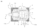
- FIG. 1 is a sectional view of a vacuum valve according to Embodiment 1 of the present invention.
- a vacuum valve 4 has a cylindrical insulating cylinder 1 made of an insulating material such as ceramic, and both end openings of the insulating cylinder 1 are closed by a fixed flange 2 and a movable flange 3 respectively.
- a cylindrical arc shield (hereinafter referred to as a shield) 5 is installed inside the insulating cylinder 1.
- a fixed-side rod 6 is connected to the fixed-side flange 2, and a movable-side rod 7 passes through the movable-side flange 3 so as to be movable in the direction of the axis R.
- a fixed side contact 8 connected to the fixed side rod 6 and a movable side contact 9 connected to the movable side rod 7 are attached to face each other.
- the shield 5 is drawn so that the diameter decreases toward the end, and the parallel cylindrical portion 5a parallel to the insulating cylinder 1 is smaller in diameter than the parallel cylindrical portion 5a at both ends in the direction of the axis R of the parallel cylindrical portion.
- the small-diameter portion 5b is formed.
- the movable flange 3 is provided with a bellows 11 for enabling the movable rod 7 to move in the axial direction.
- the bellows 11 is made of metal.
- the end portion of the bellows 11 on the movable contact 9 side is joined to the U-shaped bottom surface of the inverted U-shaped bellows cover 10 through which the movable rod 7 penetrates and is joined.
- the movable rod 7 is driven in the axial direction by an operating mechanism (not shown), whereby the movable contact 9 is brought into contact with or separated from the fixed contact 8.
- the periphery of the insulating cylinder 1 including the fixed flange 2 is covered with a fixed insulating cover 12 a in the periphery of the insulating cylinder 1 except for the outer periphery of the shield 5.
- the periphery of the movable side flange 3 including the movable side flange 3 is covered with a movable side insulator cover 12b.
- the fixed side flange 2 is connected to a current-carrying terminal (not shown) or a fixing jig for the tank, the end surface X of the fixed side flange 2 is not covered with the fixed-side insulator cover 12a.
- the fixed side flange 2 is covered with the fixed side insulator cover 12a only at the outer periphery.
- surroundings of the insulating cylinder 1 except the outer peripheral part of the shield 5 mentioned above should just be the circumference
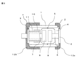
- FIG. 2 is a sectional view showing a modification of the first embodiment of the present invention.
- the corner portion Y of the fixed-side insulator cover 12a shown in FIG. 1 or the corner portion Z of the movable-side insulator cover 12b may be processed into a curved surface as shown in FIG. By doing so, the electric field concentration around the ends of the fixed-side insulator cover 12a or the movable-side insulator cover 12b can be alleviated, so that the withstand voltage performance can be improved.
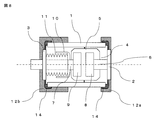
- FIG. 3 is a cross-sectional view of a vacuum valve showing a further modification of the first embodiment of the present invention.
- the end portion Q or the end portion P on the opposite side of the fixed-side insulator cover 12a or the movable-side insulator cover 12b shown in FIG. 1 has a right section, but has a curved surface as shown in FIG. May be processed.
- the electric field concentration around the ends of the fixed-side insulator cover 12a or the movable-side insulator cover 12b can be alleviated, so that the withstand voltage performance can be improved.
- the shield 5 is electrically connected to neither the fixed-side device nor the movable-side device, and between the fixed-side device and the shield 5 and between the movable-side device and the shield 5.
- the electric potential is determined by a capacitance component determined by the distance between the shield 5 and the member and the separation distance between the shield 5 and the ground. Therefore, the structure in which the outer periphery of the insulating cylinder other than the shield 5 is covered with the fixed-side insulator cover 12a and the movable-side insulator cover 12b has a capacity between the shield 5 and the ground rather than the structure in which the entire vacuum valve 4 is molded with an insulator.
- the potential drop of the shield 5 can be suppressed.
- the periphery of the insulating cylinder 1 on the outer peripheral portion of the small-diameter portion 5b forming the shield 5 is covered with the fixed-side insulator cover 12a or the movable-side insulator cover 12b, the potential drop of the shield 5 is suppressed. Is sufficiently possible.
- Embodiment 2 A heat-shrinkable member is used as the material for the fixed-side insulator cover 12a and the movable-side insulator cover 12b described in the first embodiment.
- a fixed-side insulator cover 12a and a movable-side insulator cover 12b formed of a heat-shrinkable member are inserted into the opening of the insulating tube 1 of the vacuum valve 4, it is put into a furnace and heated. Since the heat shrink member is formed as described above, the fixed-side insulator cover 12a and the movable-side insulator cover 12b can be fixed easily and surely.
- the fixed side and movable side covers are formed of resin or the like, in order to prevent the cover from coming off due to the impact when the vacuum valve 4 is driven, although it is necessary to fix with an agent, etc., when the fixed-side insulator cover 12a and the movable-side insulator cover 12b are formed with a heat-shrinkable member, it can be fixed without using an adhesive, improving workability To do.
- the fixed-side insulator cover 12a covers from the fixed-side flange 2 to the connecting portion between the shield 5 and the fixed-side insulating cylinder 1a, and the movable-side insulator cover 12b extends from the movable-side flange 3 to the shield 5 and the movable-side insulation. Covers up to cylinder 1b.
- the fixed-side flange 2 is connected to a current-carrying terminal (not shown) or a fixing jig for the tank, so that the end face X in FIG. 4 is not covered with the fixed-side insulator cover 12a.
- the fixed-side flange 2 is covered with the fixed-side insulator cover 12a only at the outer periphery.
- the movable insulator cover 12b is provided with a cylindrical hole in the central portion in the axial direction so that the movable rod 7 can be driven.
- FIG. 5 is a sectional view showing a modification of the third embodiment of the present invention shown in FIG.
- the shield 5 is accommodated in the fixed insulating cylinder 1a and the movable insulating cylinder 1b by setting the outer diameter of the shield 5 to be equal to or smaller than the inner diameter of the fixed insulating cylinder 1a and the movable insulating cylinder 1b.
- the fixed-side insulating cover 12 a and the movable-side insulating cover 12 b are not installed on the outer periphery of the fixed-side insulating cylinder 1 a that houses the shield 5 and the movable-side insulating cylinder 1 b. Is done.
- the shield 5 is not electrically connected to the fixed-side device and the movable-side device, and has a potential determined by the capacitance component between the surrounding members.
- the shield 5 is housed in the fixed-side insulating cylinder 1 a and the movable-side insulating cylinder 1 b, but the fixed-side insulator cover 12 a and the movable-side insulator cover 12 b do not overlap the outer periphery of the shield 5.
- the potential drop of the shield 5 can be prevented as in the first embodiment.
- FIG. 6 is a cross-sectional view of a vacuum valve according to Embodiment 4 of the present invention.
- a cylindrical or conductive electric field relaxation shield 13 having a distal end curved inward is disposed so as to cover the connecting portion between the insulating cylinder 1 and the fixed flange 2 or the insulating cylinder 1 and the movable flange 3. After that, the connecting portion is sealed.
- the distal end portion of the electric field relaxation shield 13 is more than the sealing portion between the insulating cylinder 1 and the fixed side flange 2 and the sealing portion between the insulating cylinder 1 and the movable side flange 3. , Arrange them so that they are located on the contact side.
- the fixed-side insulator cover 12a and the movable-side insulator cover 12b are manufactured by insulating molding the electric field relaxation shield 13, for example.
- the location A where the insulating cylinder 1, the fixed side flange 2 and the fixed side insulator cover 12a are in contact, or the location B where the insulating cylinder 1, the movable side flange 3 and the movable side insulator cover 12b are in contact is metal, This is a triple point where three kinds of materials of ceramic and insulator are in contact with each other, and the electric field value is very high.
- a conductor or semiconductor electric field relaxation shield 13 having a cylindrical shape and a tip having a bay-shaped curved portion in the inner circumferential direction is installed.
- the electric field relaxation shield 13 relaxes the three-point electric field, thereby improving the withstand voltage performance of the vacuum valve 4. Thereby, for example, it is not necessary to implement measures for improving the withstand voltage performance such as increasing the thickness of the insulator cover that covers the vacuum valve 4, and the vacuum valve can be downsized.
- FIG. 8 is a cross-sectional view of a vacuum valve according to Embodiment 5 of the present invention.
- a conductive rubber 14 is attached to cover the sealing portion between the insulating cylinder 1 and the fixed flange 2 and the sealing portion between the insulating cylinder 1 and the movable flange 3. Further, a fixed-side insulator cover 12a and a movable-side insulator cover 12b are installed so as to cover the conductive rubber 14. After the conductive rubber 14 is mounted, the fixed-side insulator cover 12a and the movable-side insulator cover 12b may be installed. However, the withstand voltage performance may be deteriorated due to surface pressure or displacement at the interface between the two. is there. Therefore, if the conductive rubber 14 and the fixed-side insulator cover 12a, or the conductive rubber 14 and the movable-side insulator cover 12b are molded integrally, the attachment becomes easy.
- the withstand voltage performance of the vacuum valve 4 is improved. Thereby, for example, it is not necessary to implement measures for improving the withstand voltage performance such as increasing the thickness of the fixed insulator cover 12a and the movable insulator cover 12b covering the vacuum valve 4, and the vacuum valve 4 can be reduced in size. Can do. Further, if the conductive rubber 14 and the fixed-side insulator cover 12a or the movable-side insulator cover 12b are integrally molded, the attachment to the vacuum valve 4 is facilitated.
- 1 insulating cylinder
- 1a fixed insulating cylinder
- 1b movable insulating cylinder
- 2 fixed flange
- 3 movable flange
- 4 vacuum valve
- 5 Arc shield
- 6 Fixed side rod
- 7 Movable side rod
- 8 fixed contact
- 9 movable contact
- 10 bellows cover
- 11 Bellows
- 12a Fixed insulator cover
- 12b movable insulator cover
- 13 Electric field relaxation shield
- 14 Conductive rubber.
Landscapes
- High-Tension Arc-Extinguishing Switches Without Spraying Means (AREA)
Abstract
La présente invention concerne une soupape de dépression pourvue d'un récipient sous vide dans lequel les deux parties d'extrémité d'un cylindre d'isolation sont scellées hermétiquement par un élément d'étanchéité, un contact côté fixe est fixé dans le récipient sous vide avec un conducteur interposé entre celles-ci, et un contact côté mobile pouvant être entraîné est disposé de façon à faire face au contact côté fixe, la soupape de dépression étant caractérisée en ce qu'un isolant destiné à recouvrir le cylindre d'isolation est disposé partout à l'exception de la partie périphérique extérieure d'un blindage disposé de manière à entourer le contact côté fixe et le contact côté mobile.
Priority Applications (1)
| Application Number | Priority Date | Filing Date | Title |
|---|---|---|---|
| PCT/JP2017/002239 WO2018138754A1 (fr) | 2017-01-24 | 2017-01-24 | Soupape de dépression |
Applications Claiming Priority (1)
| Application Number | Priority Date | Filing Date | Title |
|---|---|---|---|
| PCT/JP2017/002239 WO2018138754A1 (fr) | 2017-01-24 | 2017-01-24 | Soupape de dépression |
Publications (1)
| Publication Number | Publication Date |
|---|---|
| WO2018138754A1 true WO2018138754A1 (fr) | 2018-08-02 |
Family
ID=62978201
Family Applications (1)
| Application Number | Title | Priority Date | Filing Date |
|---|---|---|---|
| PCT/JP2017/002239 Ceased WO2018138754A1 (fr) | 2017-01-24 | 2017-01-24 | Soupape de dépression |
Country Status (1)
| Country | Link |
|---|---|
| WO (1) | WO2018138754A1 (fr) |
Cited By (1)
| Publication number | Priority date | Publication date | Assignee | Title |
|---|---|---|---|---|
| EP4567849A1 (fr) * | 2023-12-08 | 2025-06-11 | Schneider Electric Industries Sas | Ampoule à vide de moyenne ou haute tension |
Citations (4)
| Publication number | Priority date | Publication date | Assignee | Title |
|---|---|---|---|---|
| JP2004235120A (ja) * | 2003-02-03 | 2004-08-19 | Japan Ae Power Systems Corp | 絶縁管型真空遮断器 |
| JP2009252475A (ja) * | 2008-04-04 | 2009-10-29 | Mitsubishi Electric Corp | 開閉器装置 |
| JP2011048998A (ja) * | 2009-08-26 | 2011-03-10 | Toshiba Corp | モールド真空バルブ |
| JP2014510989A (ja) * | 2010-10-01 | 2014-05-01 | アーべーべー・テヒノロギー・リミテッド | 選択的カプセル封じを含むコンパクトな真空遮断器 |
-
2017
- 2017-01-24 WO PCT/JP2017/002239 patent/WO2018138754A1/fr not_active Ceased
Patent Citations (4)
| Publication number | Priority date | Publication date | Assignee | Title |
|---|---|---|---|---|
| JP2004235120A (ja) * | 2003-02-03 | 2004-08-19 | Japan Ae Power Systems Corp | 絶縁管型真空遮断器 |
| JP2009252475A (ja) * | 2008-04-04 | 2009-10-29 | Mitsubishi Electric Corp | 開閉器装置 |
| JP2011048998A (ja) * | 2009-08-26 | 2011-03-10 | Toshiba Corp | モールド真空バルブ |
| JP2014510989A (ja) * | 2010-10-01 | 2014-05-01 | アーべーべー・テヒノロギー・リミテッド | 選択的カプセル封じを含むコンパクトな真空遮断器 |
Cited By (2)
| Publication number | Priority date | Publication date | Assignee | Title |
|---|---|---|---|---|
| EP4567849A1 (fr) * | 2023-12-08 | 2025-06-11 | Schneider Electric Industries Sas | Ampoule à vide de moyenne ou haute tension |
| FR3156580A1 (fr) * | 2023-12-08 | 2025-06-13 | Schneider Electric Industries Sas | Ampoule à vide de moyenne ou haute tension |
Similar Documents
| Publication | Publication Date | Title |
|---|---|---|
| CN106133869B (zh) | 断路设备 | |
| US8227720B2 (en) | Vacuum switch and vacuum switchgear | |
| JP5596958B2 (ja) | 架空線取合いブッシング | |
| RU2543984C2 (ru) | Компактный вакуумный прерыватель с избирательным инкапсулированием | |
| CN104252993A (zh) | 箱式真空断路器 | |
| JP4845745B2 (ja) | 真空開閉器 | |
| WO2017159588A1 (fr) | Condensateur de division de tension | |
| WO2018138754A1 (fr) | Soupape de dépression | |
| CN114503235B (zh) | 具有真空灭弧室的断路器 | |
| JP2009093922A (ja) | 真空バルブ | |
| JP2014026854A (ja) | 真空開閉器及びそれを用いたスイッチギヤ | |
| JP5171298B2 (ja) | 樹脂モールド真空バルブ | |
| JP5971676B2 (ja) | 真空遮断器 | |
| JP4660303B2 (ja) | 固体絶縁スイッチギヤ | |
| JP2003319515A (ja) | ガス絶縁開閉装置 | |
| JP2006080036A (ja) | 真空遮断装置 | |
| US11862419B2 (en) | Toroidal encapsulation for high voltage vacuum interrupters | |
| JP2016208809A (ja) | スイッチギヤ | |
| CN218996595U (zh) | 一种具有热缩管的断路器用陶瓷真空灭弧室 | |
| JP3833444B2 (ja) | モールド真空バルブ及びその製造方法 | |
| JP4102967B2 (ja) | 絶縁ブッシングおよびスイッチギア | |
| JP6175295B2 (ja) | タンク形真空遮断器 | |
| JP2560370Y2 (ja) | 真空インタラプタと開閉装置 | |
| WO2016171047A1 (fr) | Appareillage de connexion | |
| WO2020031437A1 (fr) | Commutateur à vide et son procédé de fabrication |
Legal Events
| Date | Code | Title | Description |
|---|---|---|---|
| 121 | Ep: the epo has been informed by wipo that ep was designated in this application |
Ref document number: 17893675 Country of ref document: EP Kind code of ref document: A1 |
|
| NENP | Non-entry into the national phase |
Ref country code: DE |
|
| 122 | Ep: pct application non-entry in european phase |
Ref document number: 17893675 Country of ref document: EP Kind code of ref document: A1 |
|
| NENP | Non-entry into the national phase |
Ref country code: JP |