WO2018142876A1 - Film composite de graphite et son procédé de fabrication - Google Patents
Film composite de graphite et son procédé de fabrication Download PDFInfo
- Publication number
- WO2018142876A1 WO2018142876A1 PCT/JP2018/000610 JP2018000610W WO2018142876A1 WO 2018142876 A1 WO2018142876 A1 WO 2018142876A1 JP 2018000610 W JP2018000610 W JP 2018000610W WO 2018142876 A1 WO2018142876 A1 WO 2018142876A1
- Authority
- WO
- WIPO (PCT)
- Prior art keywords
- film
- metal
- layer
- conductive adhesive
- graphite
- Prior art date
- Legal status (The legal status is an assumption and is not a legal conclusion. Google has not performed a legal analysis and makes no representation as to the accuracy of the status listed.)
- Ceased
Links
Images












Classifications
-
- B—PERFORMING OPERATIONS; TRANSPORTING
- B32—LAYERED PRODUCTS
- B32B—LAYERED PRODUCTS, i.e. PRODUCTS BUILT-UP OF STRATA OF FLAT OR NON-FLAT, e.g. CELLULAR OR HONEYCOMB, FORM
- B32B9/00—Layered products comprising a layer of a particular substance not covered by groups B32B11/00 - B32B29/00
- B32B9/04—Layered products comprising a layer of a particular substance not covered by groups B32B11/00 - B32B29/00 comprising such particular substance as the main or only constituent of a layer, which is next to another layer of the same or of a different material
-
- B—PERFORMING OPERATIONS; TRANSPORTING
- B32—LAYERED PRODUCTS
- B32B—LAYERED PRODUCTS, i.e. PRODUCTS BUILT-UP OF STRATA OF FLAT OR NON-FLAT, e.g. CELLULAR OR HONEYCOMB, FORM
- B32B9/00—Layered products comprising a layer of a particular substance not covered by groups B32B11/00 - B32B29/00
- B32B9/005—Layered products comprising a layer of a particular substance not covered by groups B32B11/00 - B32B29/00 comprising one layer of ceramic material, e.g. porcelain, ceramic tile
- B32B9/007—Layered products comprising a layer of a particular substance not covered by groups B32B11/00 - B32B29/00 comprising one layer of ceramic material, e.g. porcelain, ceramic tile comprising carbon, e.g. graphite, composite carbon
-
- B—PERFORMING OPERATIONS; TRANSPORTING
- B32—LAYERED PRODUCTS
- B32B—LAYERED PRODUCTS, i.e. PRODUCTS BUILT-UP OF STRATA OF FLAT OR NON-FLAT, e.g. CELLULAR OR HONEYCOMB, FORM
- B32B15/00—Layered products comprising a layer of metal
- B32B15/04—Layered products comprising a layer of metal comprising metal as the main or only constituent of a layer, which is next to another layer of the same or of a different material
- B32B15/08—Layered products comprising a layer of metal comprising metal as the main or only constituent of a layer, which is next to another layer of the same or of a different material of synthetic resin
-
- B—PERFORMING OPERATIONS; TRANSPORTING
- B32—LAYERED PRODUCTS
- B32B—LAYERED PRODUCTS, i.e. PRODUCTS BUILT-UP OF STRATA OF FLAT OR NON-FLAT, e.g. CELLULAR OR HONEYCOMB, FORM
- B32B15/00—Layered products comprising a layer of metal
- B32B15/04—Layered products comprising a layer of metal comprising metal as the main or only constituent of a layer, which is next to another layer of the same or of a different material
- B32B15/08—Layered products comprising a layer of metal comprising metal as the main or only constituent of a layer, which is next to another layer of the same or of a different material of synthetic resin
- B32B15/082—Layered products comprising a layer of metal comprising metal as the main or only constituent of a layer, which is next to another layer of the same or of a different material of synthetic resin comprising vinyl resins; comprising acrylic resins
-
- B—PERFORMING OPERATIONS; TRANSPORTING
- B32—LAYERED PRODUCTS
- B32B—LAYERED PRODUCTS, i.e. PRODUCTS BUILT-UP OF STRATA OF FLAT OR NON-FLAT, e.g. CELLULAR OR HONEYCOMB, FORM
- B32B15/00—Layered products comprising a layer of metal
- B32B15/04—Layered products comprising a layer of metal comprising metal as the main or only constituent of a layer, which is next to another layer of the same or of a different material
- B32B15/08—Layered products comprising a layer of metal comprising metal as the main or only constituent of a layer, which is next to another layer of the same or of a different material of synthetic resin
- B32B15/085—Layered products comprising a layer of metal comprising metal as the main or only constituent of a layer, which is next to another layer of the same or of a different material of synthetic resin comprising polyolefins
-
- B—PERFORMING OPERATIONS; TRANSPORTING
- B32—LAYERED PRODUCTS
- B32B—LAYERED PRODUCTS, i.e. PRODUCTS BUILT-UP OF STRATA OF FLAT OR NON-FLAT, e.g. CELLULAR OR HONEYCOMB, FORM
- B32B15/00—Layered products comprising a layer of metal
- B32B15/04—Layered products comprising a layer of metal comprising metal as the main or only constituent of a layer, which is next to another layer of the same or of a different material
- B32B15/08—Layered products comprising a layer of metal comprising metal as the main or only constituent of a layer, which is next to another layer of the same or of a different material of synthetic resin
- B32B15/09—Layered products comprising a layer of metal comprising metal as the main or only constituent of a layer, which is next to another layer of the same or of a different material of synthetic resin comprising polyesters
-
- B—PERFORMING OPERATIONS; TRANSPORTING
- B32—LAYERED PRODUCTS
- B32B—LAYERED PRODUCTS, i.e. PRODUCTS BUILT-UP OF STRATA OF FLAT OR NON-FLAT, e.g. CELLULAR OR HONEYCOMB, FORM
- B32B15/00—Layered products comprising a layer of metal
- B32B15/04—Layered products comprising a layer of metal comprising metal as the main or only constituent of a layer, which is next to another layer of the same or of a different material
- B32B15/12—Layered products comprising a layer of metal comprising metal as the main or only constituent of a layer, which is next to another layer of the same or of a different material of paper or cardboard
-
- B—PERFORMING OPERATIONS; TRANSPORTING
- B32—LAYERED PRODUCTS
- B32B—LAYERED PRODUCTS, i.e. PRODUCTS BUILT-UP OF STRATA OF FLAT OR NON-FLAT, e.g. CELLULAR OR HONEYCOMB, FORM
- B32B15/00—Layered products comprising a layer of metal
- B32B15/16—Layered products comprising a layer of metal next to a particulate layer
-
- B—PERFORMING OPERATIONS; TRANSPORTING
- B32—LAYERED PRODUCTS
- B32B—LAYERED PRODUCTS, i.e. PRODUCTS BUILT-UP OF STRATA OF FLAT OR NON-FLAT, e.g. CELLULAR OR HONEYCOMB, FORM
- B32B15/00—Layered products comprising a layer of metal
- B32B15/20—Layered products comprising a layer of metal comprising aluminium or copper
-
- B—PERFORMING OPERATIONS; TRANSPORTING
- B32—LAYERED PRODUCTS
- B32B—LAYERED PRODUCTS, i.e. PRODUCTS BUILT-UP OF STRATA OF FLAT OR NON-FLAT, e.g. CELLULAR OR HONEYCOMB, FORM
- B32B27/00—Layered products comprising a layer of synthetic resin
- B32B27/06—Layered products comprising a layer of synthetic resin as the main or only constituent of a layer, which is next to another layer of the same or of a different material
- B32B27/10—Layered products comprising a layer of synthetic resin as the main or only constituent of a layer, which is next to another layer of the same or of a different material of paper or cardboard
-
- B—PERFORMING OPERATIONS; TRANSPORTING
- B32—LAYERED PRODUCTS
- B32B—LAYERED PRODUCTS, i.e. PRODUCTS BUILT-UP OF STRATA OF FLAT OR NON-FLAT, e.g. CELLULAR OR HONEYCOMB, FORM
- B32B27/00—Layered products comprising a layer of synthetic resin
- B32B27/18—Layered products comprising a layer of synthetic resin characterised by the use of special additives
-
- B—PERFORMING OPERATIONS; TRANSPORTING
- B32—LAYERED PRODUCTS
- B32B—LAYERED PRODUCTS, i.e. PRODUCTS BUILT-UP OF STRATA OF FLAT OR NON-FLAT, e.g. CELLULAR OR HONEYCOMB, FORM
- B32B27/00—Layered products comprising a layer of synthetic resin
- B32B27/28—Layered products comprising a layer of synthetic resin comprising synthetic resins not wholly covered by any one of the sub-groups B32B27/30 - B32B27/42
- B32B27/283—Layered products comprising a layer of synthetic resin comprising synthetic resins not wholly covered by any one of the sub-groups B32B27/30 - B32B27/42 comprising polysiloxanes
-
- B—PERFORMING OPERATIONS; TRANSPORTING
- B32—LAYERED PRODUCTS
- B32B—LAYERED PRODUCTS, i.e. PRODUCTS BUILT-UP OF STRATA OF FLAT OR NON-FLAT, e.g. CELLULAR OR HONEYCOMB, FORM
- B32B27/00—Layered products comprising a layer of synthetic resin
- B32B27/32—Layered products comprising a layer of synthetic resin comprising polyolefins
-
- B—PERFORMING OPERATIONS; TRANSPORTING
- B32—LAYERED PRODUCTS
- B32B—LAYERED PRODUCTS, i.e. PRODUCTS BUILT-UP OF STRATA OF FLAT OR NON-FLAT, e.g. CELLULAR OR HONEYCOMB, FORM
- B32B27/00—Layered products comprising a layer of synthetic resin
- B32B27/36—Layered products comprising a layer of synthetic resin comprising polyesters
-
- B—PERFORMING OPERATIONS; TRANSPORTING
- B32—LAYERED PRODUCTS
- B32B—LAYERED PRODUCTS, i.e. PRODUCTS BUILT-UP OF STRATA OF FLAT OR NON-FLAT, e.g. CELLULAR OR HONEYCOMB, FORM
- B32B37/00—Methods or apparatus for laminating, e.g. by curing or by ultrasonic bonding
- B32B37/02—Methods or apparatus for laminating, e.g. by curing or by ultrasonic bonding characterised by a sequence of laminating steps, e.g. by adding new layers at consecutive laminating stations
-
- B—PERFORMING OPERATIONS; TRANSPORTING
- B32—LAYERED PRODUCTS
- B32B—LAYERED PRODUCTS, i.e. PRODUCTS BUILT-UP OF STRATA OF FLAT OR NON-FLAT, e.g. CELLULAR OR HONEYCOMB, FORM
- B32B37/00—Methods or apparatus for laminating, e.g. by curing or by ultrasonic bonding
- B32B37/02—Methods or apparatus for laminating, e.g. by curing or by ultrasonic bonding characterised by a sequence of laminating steps, e.g. by adding new layers at consecutive laminating stations
- B32B37/025—Transfer laminating
-
- B—PERFORMING OPERATIONS; TRANSPORTING
- B32—LAYERED PRODUCTS
- B32B—LAYERED PRODUCTS, i.e. PRODUCTS BUILT-UP OF STRATA OF FLAT OR NON-FLAT, e.g. CELLULAR OR HONEYCOMB, FORM
- B32B37/00—Methods or apparatus for laminating, e.g. by curing or by ultrasonic bonding
- B32B37/12—Methods or apparatus for laminating, e.g. by curing or by ultrasonic bonding characterised by using adhesives
-
- B—PERFORMING OPERATIONS; TRANSPORTING
- B32—LAYERED PRODUCTS
- B32B—LAYERED PRODUCTS, i.e. PRODUCTS BUILT-UP OF STRATA OF FLAT OR NON-FLAT, e.g. CELLULAR OR HONEYCOMB, FORM
- B32B37/00—Methods or apparatus for laminating, e.g. by curing or by ultrasonic bonding
- B32B37/14—Methods or apparatus for laminating, e.g. by curing or by ultrasonic bonding characterised by the properties of the layers
- B32B37/144—Methods or apparatus for laminating, e.g. by curing or by ultrasonic bonding characterised by the properties of the layers using layers with different mechanical or chemical conditions or properties, e.g. layers with different thermal shrinkage, layers under tension during bonding
-
- B—PERFORMING OPERATIONS; TRANSPORTING
- B32—LAYERED PRODUCTS
- B32B—LAYERED PRODUCTS, i.e. PRODUCTS BUILT-UP OF STRATA OF FLAT OR NON-FLAT, e.g. CELLULAR OR HONEYCOMB, FORM
- B32B37/00—Methods or apparatus for laminating, e.g. by curing or by ultrasonic bonding
- B32B37/14—Methods or apparatus for laminating, e.g. by curing or by ultrasonic bonding characterised by the properties of the layers
- B32B37/16—Methods or apparatus for laminating, e.g. by curing or by ultrasonic bonding characterised by the properties of the layers with all layers existing as coherent layers before laminating
- B32B37/20—Methods or apparatus for laminating, e.g. by curing or by ultrasonic bonding characterised by the properties of the layers with all layers existing as coherent layers before laminating involving the assembly of continuous webs only
-
- B—PERFORMING OPERATIONS; TRANSPORTING
- B32—LAYERED PRODUCTS
- B32B—LAYERED PRODUCTS, i.e. PRODUCTS BUILT-UP OF STRATA OF FLAT OR NON-FLAT, e.g. CELLULAR OR HONEYCOMB, FORM
- B32B38/00—Ancillary operations in connection with laminating processes
- B32B38/10—Removing layers, or parts of layers, mechanically or chemically
-
- B—PERFORMING OPERATIONS; TRANSPORTING
- B32—LAYERED PRODUCTS
- B32B—LAYERED PRODUCTS, i.e. PRODUCTS BUILT-UP OF STRATA OF FLAT OR NON-FLAT, e.g. CELLULAR OR HONEYCOMB, FORM
- B32B7/00—Layered products characterised by the relation between layers; Layered products characterised by the relative orientation of features between layers, or by the relative values of a measurable parameter between layers, i.e. products comprising layers having different physical, chemical or physicochemical properties; Layered products characterised by the interconnection of layers
- B32B7/04—Interconnection of layers
- B32B7/06—Interconnection of layers permitting easy separation
-
- B—PERFORMING OPERATIONS; TRANSPORTING
- B32—LAYERED PRODUCTS
- B32B—LAYERED PRODUCTS, i.e. PRODUCTS BUILT-UP OF STRATA OF FLAT OR NON-FLAT, e.g. CELLULAR OR HONEYCOMB, FORM
- B32B7/00—Layered products characterised by the relation between layers; Layered products characterised by the relative orientation of features between layers, or by the relative values of a measurable parameter between layers, i.e. products comprising layers having different physical, chemical or physicochemical properties; Layered products characterised by the interconnection of layers
- B32B7/04—Interconnection of layers
- B32B7/12—Interconnection of layers using interposed adhesives or interposed materials with bonding properties
-
- B—PERFORMING OPERATIONS; TRANSPORTING
- B32—LAYERED PRODUCTS
- B32B—LAYERED PRODUCTS, i.e. PRODUCTS BUILT-UP OF STRATA OF FLAT OR NON-FLAT, e.g. CELLULAR OR HONEYCOMB, FORM
- B32B9/00—Layered products comprising a layer of a particular substance not covered by groups B32B11/00 - B32B29/00
-
- B—PERFORMING OPERATIONS; TRANSPORTING
- B32—LAYERED PRODUCTS
- B32B—LAYERED PRODUCTS, i.e. PRODUCTS BUILT-UP OF STRATA OF FLAT OR NON-FLAT, e.g. CELLULAR OR HONEYCOMB, FORM
- B32B9/00—Layered products comprising a layer of a particular substance not covered by groups B32B11/00 - B32B29/00
- B32B9/04—Layered products comprising a layer of a particular substance not covered by groups B32B11/00 - B32B29/00 comprising such particular substance as the main or only constituent of a layer, which is next to another layer of the same or of a different material
- B32B9/041—Layered products comprising a layer of a particular substance not covered by groups B32B11/00 - B32B29/00 comprising such particular substance as the main or only constituent of a layer, which is next to another layer of the same or of a different material of metal
-
- B—PERFORMING OPERATIONS; TRANSPORTING
- B32—LAYERED PRODUCTS
- B32B—LAYERED PRODUCTS, i.e. PRODUCTS BUILT-UP OF STRATA OF FLAT OR NON-FLAT, e.g. CELLULAR OR HONEYCOMB, FORM
- B32B9/00—Layered products comprising a layer of a particular substance not covered by groups B32B11/00 - B32B29/00
- B32B9/04—Layered products comprising a layer of a particular substance not covered by groups B32B11/00 - B32B29/00 comprising such particular substance as the main or only constituent of a layer, which is next to another layer of the same or of a different material
- B32B9/045—Layered products comprising a layer of a particular substance not covered by groups B32B11/00 - B32B29/00 comprising such particular substance as the main or only constituent of a layer, which is next to another layer of the same or of a different material of synthetic resin
-
- C—CHEMISTRY; METALLURGY
- C01—INORGANIC CHEMISTRY
- C01B—NON-METALLIC ELEMENTS; COMPOUNDS THEREOF; METALLOIDS OR COMPOUNDS THEREOF NOT COVERED BY SUBCLASS C01C
- C01B32/00—Carbon; Compounds thereof
- C01B32/20—Graphite
-
- C—CHEMISTRY; METALLURGY
- C01—INORGANIC CHEMISTRY
- C01B—NON-METALLIC ELEMENTS; COMPOUNDS THEREOF; METALLOIDS OR COMPOUNDS THEREOF NOT COVERED BY SUBCLASS C01C
- C01B32/00—Carbon; Compounds thereof
- C01B32/20—Graphite
- C01B32/205—Preparation
-
- B—PERFORMING OPERATIONS; TRANSPORTING
- B32—LAYERED PRODUCTS
- B32B—LAYERED PRODUCTS, i.e. PRODUCTS BUILT-UP OF STRATA OF FLAT OR NON-FLAT, e.g. CELLULAR OR HONEYCOMB, FORM
- B32B37/00—Methods or apparatus for laminating, e.g. by curing or by ultrasonic bonding
- B32B37/14—Methods or apparatus for laminating, e.g. by curing or by ultrasonic bonding characterised by the properties of the layers
- B32B37/24—Methods or apparatus for laminating, e.g. by curing or by ultrasonic bonding characterised by the properties of the layers with at least one layer not being coherent before laminating, e.g. made up from granular material sprinkled onto a substrate
- B32B2037/243—Coating
-
- B—PERFORMING OPERATIONS; TRANSPORTING
- B32—LAYERED PRODUCTS
- B32B—LAYERED PRODUCTS, i.e. PRODUCTS BUILT-UP OF STRATA OF FLAT OR NON-FLAT, e.g. CELLULAR OR HONEYCOMB, FORM
- B32B2255/00—Coating on the layer surface
- B32B2255/10—Coating on the layer surface on synthetic resin layer or on natural or synthetic rubber layer
-
- B—PERFORMING OPERATIONS; TRANSPORTING
- B32—LAYERED PRODUCTS
- B32B—LAYERED PRODUCTS, i.e. PRODUCTS BUILT-UP OF STRATA OF FLAT OR NON-FLAT, e.g. CELLULAR OR HONEYCOMB, FORM
- B32B2255/00—Coating on the layer surface
- B32B2255/20—Inorganic coating
- B32B2255/205—Metallic coating
-
- B—PERFORMING OPERATIONS; TRANSPORTING
- B32—LAYERED PRODUCTS
- B32B—LAYERED PRODUCTS, i.e. PRODUCTS BUILT-UP OF STRATA OF FLAT OR NON-FLAT, e.g. CELLULAR OR HONEYCOMB, FORM
- B32B2255/00—Coating on the layer surface
- B32B2255/24—Organic non-macromolecular coating
-
- B—PERFORMING OPERATIONS; TRANSPORTING
- B32—LAYERED PRODUCTS
- B32B—LAYERED PRODUCTS, i.e. PRODUCTS BUILT-UP OF STRATA OF FLAT OR NON-FLAT, e.g. CELLULAR OR HONEYCOMB, FORM
- B32B2255/00—Coating on the layer surface
- B32B2255/28—Multiple coating on one surface
-
- B—PERFORMING OPERATIONS; TRANSPORTING
- B32—LAYERED PRODUCTS
- B32B—LAYERED PRODUCTS, i.e. PRODUCTS BUILT-UP OF STRATA OF FLAT OR NON-FLAT, e.g. CELLULAR OR HONEYCOMB, FORM
- B32B2307/00—Properties of the layers or laminate
- B32B2307/20—Properties of the layers or laminate having particular electrical or magnetic properties, e.g. piezoelectric
- B32B2307/202—Conductive
-
- B—PERFORMING OPERATIONS; TRANSPORTING
- B32—LAYERED PRODUCTS
- B32B—LAYERED PRODUCTS, i.e. PRODUCTS BUILT-UP OF STRATA OF FLAT OR NON-FLAT, e.g. CELLULAR OR HONEYCOMB, FORM
- B32B2307/00—Properties of the layers or laminate
- B32B2307/20—Properties of the layers or laminate having particular electrical or magnetic properties, e.g. piezoelectric
- B32B2307/212—Electromagnetic interference shielding
-
- B—PERFORMING OPERATIONS; TRANSPORTING
- B32—LAYERED PRODUCTS
- B32B—LAYERED PRODUCTS, i.e. PRODUCTS BUILT-UP OF STRATA OF FLAT OR NON-FLAT, e.g. CELLULAR OR HONEYCOMB, FORM
- B32B2307/00—Properties of the layers or laminate
- B32B2307/30—Properties of the layers or laminate having particular thermal properties
- B32B2307/302—Conductive
-
- B—PERFORMING OPERATIONS; TRANSPORTING
- B32—LAYERED PRODUCTS
- B32B—LAYERED PRODUCTS, i.e. PRODUCTS BUILT-UP OF STRATA OF FLAT OR NON-FLAT, e.g. CELLULAR OR HONEYCOMB, FORM
- B32B2307/00—Properties of the layers or laminate
- B32B2307/50—Properties of the layers or laminate having particular mechanical properties
- B32B2307/546—Flexural strength; Flexion stiffness
-
- B—PERFORMING OPERATIONS; TRANSPORTING
- B32—LAYERED PRODUCTS
- B32B—LAYERED PRODUCTS, i.e. PRODUCTS BUILT-UP OF STRATA OF FLAT OR NON-FLAT, e.g. CELLULAR OR HONEYCOMB, FORM
- B32B2307/00—Properties of the layers or laminate
- B32B2307/70—Other properties
- B32B2307/714—Inert, i.e. inert to chemical degradation, corrosion
-
- B—PERFORMING OPERATIONS; TRANSPORTING
- B32—LAYERED PRODUCTS
- B32B—LAYERED PRODUCTS, i.e. PRODUCTS BUILT-UP OF STRATA OF FLAT OR NON-FLAT, e.g. CELLULAR OR HONEYCOMB, FORM
- B32B2307/00—Properties of the layers or laminate
- B32B2307/70—Other properties
- B32B2307/732—Dimensional properties
-
- B—PERFORMING OPERATIONS; TRANSPORTING
- B32—LAYERED PRODUCTS
- B32B—LAYERED PRODUCTS, i.e. PRODUCTS BUILT-UP OF STRATA OF FLAT OR NON-FLAT, e.g. CELLULAR OR HONEYCOMB, FORM
- B32B2307/00—Properties of the layers or laminate
- B32B2307/70—Other properties
- B32B2307/748—Releasability
-
- B—PERFORMING OPERATIONS; TRANSPORTING
- B32—LAYERED PRODUCTS
- B32B—LAYERED PRODUCTS, i.e. PRODUCTS BUILT-UP OF STRATA OF FLAT OR NON-FLAT, e.g. CELLULAR OR HONEYCOMB, FORM
- B32B2457/00—Electrical equipment
-
- B—PERFORMING OPERATIONS; TRANSPORTING
- B32—LAYERED PRODUCTS
- B32B—LAYERED PRODUCTS, i.e. PRODUCTS BUILT-UP OF STRATA OF FLAT OR NON-FLAT, e.g. CELLULAR OR HONEYCOMB, FORM
- B32B2457/00—Electrical equipment
- B32B2457/20—Displays, e.g. liquid crystal displays, plasma displays
- B32B2457/202—LCD, i.e. liquid crystal displays
Definitions
- the present disclosure relates to a graphite composite film and a manufacturing method thereof.
- Patent Document 1 discloses that a graphite film, a conductive adhesive layer having a surface resistance within a predetermined range, a metal thin film made of copper, and a protective film layer are laminated in this order. An improved graphite composite film is disclosed.
- an object of the present disclosure is to provide a graphite composite film that can simultaneously realize a countermeasure against heat and a countermeasure against electromagnetic noise, and whose electromagnetic shielding properties hardly deteriorate with time, and a method for manufacturing the same.
- the graphite composite film according to the first aspect includes a graphite layer, a first conductive adhesive layer, and a metal layer containing a first metal in this order.
- the first rust-proofing layer is interposed between the first conductive adhesive layer and the metal layer, and the second rust-proofing layer is arranged with the first rust-proofing layer of the metal layer. It is arrange
- a first metal is deposited on the first surface of the protective film having the first surface and the second surface to form a metal layer, and the first layer is formed on the surface of the metal layer.
- the first rust prevention treatment layer is formed by applying one rust prevention treatment, the first conductive adhesive sheet is disposed and laminated on the surface of the first rust prevention treatment layer, the protective film is peeled off, Conductive adhesive sheet by forming a second antirust treatment layer by applying a second antirust treatment to the surface of the metal layer opposite to the surface on which the first antirust treatment layer is disposed A step of preparing a metal-deposited metal film.
- This manufacturing method further includes a step of preparing a graphite film with a conductive adhesive sheet by placing and laminating a second conductive adhesive sheet on the first surface of the graphite film having the first surface and the second surface. Including.
- the manufacturing method further includes laminating a metal vapor-deposited film with a conductive adhesive sheet and a graphite film with a conductive adhesive sheet so that the surface of the first conductive adhesive sheet and the second surface of the graphite film overlap. Including the step of.
- the second metal and the first metal are vapor-deposited in this order on the first surface of the protective film having the first surface and the second surface.
- This manufacturing method further includes a step of preparing a graphite film with a conductive adhesive sheet by placing and laminating a second conductive adhesive sheet on the first surface of the graphite film having the first surface and the second surface. Including.
- the manufacturing method further includes laminating a metal vapor-deposited film with a conductive adhesive sheet and a graphite film with a conductive adhesive sheet so that the surface of the first conductive adhesive sheet and the second surface of the graphite film overlap. Including the step of.
- the graphite layer, the first conductive adhesive layer, the metal layer containing the first metal, and the protective film are arranged in this order, And interposed between the first conductive adhesive layer and the metal layer.
- a method for producing a graphite composite film comprising: depositing a first metal on a first surface of a protective film having a first surface and a second surface to form a metal layer; It includes a step of preparing a metal vapor deposition film with a conductive adhesive sheet by forming a rust-proofing layer by performing a rust treatment, and arranging and laminating a first conductive adhesive sheet on the surface of the rust-proofing layer.
- This manufacturing method further includes a step of preparing a graphite film with a conductive adhesive sheet by placing and laminating a second conductive adhesive sheet on the first surface of the graphite film having the first surface and the second surface. Including.
- the manufacturing method further includes laminating a metal vapor-deposited film with a conductive adhesive sheet and a graphite film with a conductive adhesive sheet so that the surface of the first conductive adhesive sheet and the second surface of the graphite film overlap. Including the step of.
- This disclosure can simultaneously realize a countermeasure against heat and a countermeasure against electromagnetic noise, and the electromagnetic shielding property is hardly deteriorated.
- Outline of part of the method for producing a graphite composite film according to the first and second embodiments of the present disclosure specifically, a step of laminating a metal vapor-deposited film with a conductive adhesive sheet and a graphite film with a conductive adhesive sheet.
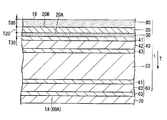
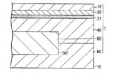
- FIG. 1A is a schematic cross-sectional view of the main body of the graphite composite film 1 according to the first embodiment.
- FIG. 1B is a schematic cross-sectional view of an end portion of the graphite composite film 1.
- the graphite composite film 1 includes a second conductive adhesive layer 60, a graphite layer 50, a first conductive adhesive layer 40, a metal layer 20, and a first layer.
- the antirust treatment layer 30, the second antirust treatment layer 80, and the first release sheet 70 are included.
- the metal layer 20 includes a first metal.
- the second conductive adhesive layer 60, the graphite layer 50, the first conductive adhesive layer 40, and the metal layer 20 are laminated in this order.
- the first antirust treatment layer 30 is interposed between the first conductive adhesive layer 40 and the metal layer 20.
- the second antirust treatment layer 80 is disposed on the surface of the metal layer 20 opposite to the surface on which the first antirust treatment layer 30 is disposed. Further, the first release sheet 70 is attached to the surface 60 ⁇ / b> A of the second conductive adhesive layer 60.
- the graphite composite film 1 Since the graphite composite film 1 has such a configuration, it is possible to simultaneously realize heat countermeasures and electromagnetic noise countermeasures for electromagnetic devices by simply attaching them to the adherend. That is, since the graphite layer 50 having excellent thermal conductivity is provided, the heat of the adherend can be dissipated in the plane direction of the graphite composite film 1 to lower the temperature of the adherend.
- the plane direction refers to a direction perpendicular to the thickness direction of the graphite layer 50.
- the electromagnetic waves which hit the metal layer 20 can be reflected. This is presumably because, when an electromagnetic wave hits the metal layer 20, an eddy current is generated in the metal layer 20 by electromagnetic induction, and this eddy current reflects the electromagnetic wave.
- the adherend is conductive, the metal layer 20 is electrically connected to the adherend and grounded, so eddy currents generated in the metal layer 20 are released (grounded) to the adherend. And more excellent electromagnetic shielding properties.
- the first rust prevention treatment layer 30 is interposed between the first conductive adhesive layer 40 and the metal layer 20, the first rust prevention treatment layer 30 of the metal layer 20 is disposed.
- the first surface 20A on the side is less likely to be discolored (hereinafter referred to as corrosion), and the electromagnetic shielding properties are less likely to deteriorate.
- the second antirust treatment layer 80 is disposed on the surface (second surface 20B) opposite to the first surface 20A of the metal layer 20, the second surface 20B of the metal layer 20 is discolored ( It is difficult to corrode) and the electromagnetic shielding properties are not easily deteriorated.
- first rust prevention treatment layer 30 and the second rust prevention treatment layer 80 suppress the progress of the corrosion of the metal layer 20, and the sheet resistance of the metal layer 20 is less likely to increase with time. It is presumed that the energy of the eddy current is less likely to be converted into thermal energy.
- the end surface 50E of the graphite layer 50 is not exposed as shown in FIG. 1B. That is, the end surface 50 ⁇ / b> E of the graphite layer 50 is covered with the first conductive adhesive layer 40 and the second conductive adhesive layer 60. As a result, it is possible to prevent the graphite composite film 1 from being broken due to delamination in the graphite layer 50 and at the same time to prevent the graphite layer 50 from falling off.
- the thickness of the graphite composite film 1 is preferably 15 ⁇ m or more and 800 ⁇ m or less.
- the thickness of the graphite composite film 1 can be measured based on an image obtained by observing a cross section of the graphite composite film 1 with a scanning electron microscope (SEM).
- SEM scanning electron microscope
- the thickness of each layer constituting the following graphite composite film 1 can also be measured in the same manner.
- the graphite composite film 1 can be used by, for example, peeling the first release sheet 70 from the graphite composite film 1 immediately before use and attaching it to an adherend.
- adherend include an electronic component arranged inside a housing of an electronic device.
- the electronic components include a rear chassis of a liquid crystal unit, an LED substrate having a light emitting diode (LED) light source used for a backlight of a liquid crystal image display device, a power amplifier, a large scale integrated circuit (LSI), and the like. It is done.
- the first release sheet 70 include paper, a resin film, a laminated paper obtained by laminating paper and a resin film, or a paper that has been sealed with clay, polyvinyl alcohol, etc.
- Examples of paper include craft paper, glassine paper, and high-quality paper.
- Examples of the resin film include polyethylene, polypropylene (OPP (Oriented Polypropylene), CPP (Cast Polypropylene)), polyethylene terephthalate (PET), and the like.
- the graphite composite film 1 includes a second conductive adhesive layer 60, a graphite layer 50, a first conductive adhesive layer 40, a first antirust treatment layer 30, a metal layer 20, and a second The antirust treatment layer 80 is laminated in this order.
- the present disclosure is not limited to this, and the graphite layer 50, the first conductive adhesive layer 40, the first rust prevention treatment layer 30, the metal layer 20, and the second rust prevention treatment layer 80 are arranged in this order. Any configuration may be used. And between these layers, the layer which does not inhibit the effect of this invention may be laminated
- the present disclosure is limited to this. Instead, the end surface 50E of the graphite layer 50 may be exposed.
- the end surface of the metal layer 20 is exposed, but the present disclosure is not limited thereto, and the end surface of the metal layer 20 is the second surface. It may be covered with the antirust treatment layer 80.
- the end surface of the metal layer 20 is less likely to corrode, and the electromagnetic wave shielding properties of the graphite composite film 1 are less likely to deteriorate.
- the graphite composite film 1 includes a metal layer 20. Thereby, the graphite composite film 1 has electromagnetic wave shielding properties.
- the metal layer 20 includes a first metal. What is necessary is just to select suitably as a 1st metal according to the raw material of the graphite composite film 1, for example, silver, copper, gold
- the first metal is preferably a raw material having a low volume resistivity among the raw materials of the graphite composite film 1 from the viewpoint of improving the electromagnetic wave shielding property of the graphite composite film 1, and from the viewpoint of cost. More preferably, it is copper.
- the thickness of the metal layer 20 is preferably 0.10 ⁇ m or more and 5.00 ⁇ m or less, more preferably 0.50 ⁇ m or more and 2.00 ⁇ m or less.
- the surface shape of the metal layer 20 viewed from the thickness direction T of the graphite composite film 1 is a solid shape, but the present invention is not limited to this. Examples thereof may further include a mesh shape, a wire shape, and the like. Note that the solid shape is a state in which the graphite composite film 1 is provided without a gap as viewed from the thickness direction T of the graphite composite film 1.
- the graphite composite film 1 includes a first antirust treatment layer 30 and a second antirust treatment layer 80.
- the first rust prevention treatment layer 30 is interposed between the first conductive adhesive layer 40 and the metal layer 20.
- the second antirust treatment layer 80 is disposed on the second surface 20 ⁇ / b> B of the metal layer 20. That is, the first rust prevention treatment layer 30 and the second rust prevention treatment layer 80 are respectively disposed on both surfaces of the metal layer 20.
- the graphite composite film 1 includes the first antirust treatment layer 30, the first surface 20A of the metal layer 20 is hardly corroded. This is because the first antirust treatment layer 30 makes it difficult for moisture, oxygen components, and the like contained in the first conductive adhesive layer 40 to reach the surface of the metal layer 20. It is presumed that the electrochemical reaction with the components in the first conductive adhesive layer 40 hardly proceeds.
- the graphite composite film 1 includes the second antirust treatment layer 80, the second surface 20B of the metal layer 20 is unlikely to corrode. This is because the second antirust treatment layer 80 mainly prevents moisture and oxygen components from the outside from reaching the surface of the metal layer 20, and the electrical connection between the raw material of the metal layer 20 and the components from the outside. It is presumed that the chemical reaction is difficult to proceed. Further, the second antirust treatment layer 80 can prevent the second surface 20B of the metal layer 20 from being damaged.
- first antirust treatment layer 30 and the second antirust treatment layer 80 for example, an organic film, a metal film, or the like can be used.
- the first rust prevention treatment layer 30 and the second rust prevention treatment layer 80 may be the same type of coating or different types of coating. That is, both the first rust prevention treatment layer 30 and the second rust prevention treatment layer 80 may be organic films, and both the first rust prevention treatment layer 30 and the second rust prevention treatment layer 80 are used. May be a metal film. Further, one of the first rust prevention treatment layer 30 and the second rust prevention treatment layer 80 may be an organic film and the other may be a metal film.
- the organic film may be appropriately adjusted according to the raw material of the metal layer 20, and examples thereof include a benzotriazole film, a triazineamine film, a mercaptobenzimidazole film, a thiodipropionic acid ester film, and a benzimidazole film.
- the organic film is preferably a benzotriazole film. If the organic film is a benzotriazole film, the metal layer 20 made of copper is less likely to corrode.
- the benzotriazole film is presumed to be a polymer complex film mainly composed of copper ions and a benzotriazole anion or a benzotriazole derivative anion.
- a raw material for the benzotriazole film for example, benzotriazole, a benzotriazole derivative, or the like can be used.
- the benzotriazole derivatives include benzotriazole, 2- (5-methyl-2-hydroxyphenyl) benzotriazole, 1,2,3-benzotriazole, 2- [2-hydroxy-3,5-bis ( ⁇ , ⁇ -dimethylbenzyl) phenyl] -2H-benzotriazole and the like can be used.
- a raw material for the triazine amine film for example, 2,4-diamino-6- [2'-methylimidazolyl- (1 ')]-ethyl-s-triazine can be used.
- a raw material for the mercaptobenzimidazole film for example, 2-mercaptobenzimidazole, 2-mercapto-5-methylbenzimidazole, 2-mercapto-5-methoxybenzimidazole and the like can be used.
- a raw material for the thiodipropionate film for example, distearyl-3, 3'-thiodipropionate, dilauryl-3,3'-thiodipropionate, or the like can be used.
- benzimidazole film for example, 2-methylbenzimidazole, 5-methylbenzimidazole, 1-hydroxy-5-methoxy-2-methylbenzimidazole-3-oxide, 2-aminobenzimidazole, etc. may be used. it can.
- a raw material for the metal film for example, pure metals such as zinc, nickel, chromium, titanium, aluminum, gold, silver, and palladium can be used. Further, a metal for rust prevention such as an alloy containing these pure metals can be used.
- the metal film is at least one first selected from the group consisting of zinc, nickel, chromium, titanium, aluminum, gold, silver, palladium, and alloys thereof. It is preferable that the metal for rust prevention is included. When the metal film contains the first metal for rust prevention, the metal layer 20 made of copper becomes difficult to corrode.
- the metal film more preferably contains nickel. Since nickel has a high rust prevention property, the metal layer 20 made of copper is more difficult to corrode. Moreover, since nickel has high adhesiveness with copper, the adhesiveness of the first antirust treatment layer 30 containing nickel with the metal layer 20 made of copper can be improved. For this reason, as shown in FIG. 1B, even when the end face of the metal layer 20 is exposed, moisture and oxygen components and the like from the interface 20A between the first antirust treatment layer 30 and the metal layer 20 can be removed. It becomes difficult to reach the surface.
- the metal film is at least one second selected from the group consisting of zinc, nickel, chromium, titanium, aluminum, gold, silver, palladium, and alloys thereof. It is preferable that the metal for rust prevention is included. When the metal film contains the first metal for rust prevention, the metal layer 20 made of copper becomes difficult to corrode.
- the metal film more preferably contains nickel. Since nickel has a high rust prevention property, the metal layer 20 made of copper is more difficult to corrode. Moreover, since nickel has high adhesiveness with copper, the adhesiveness with the metal layer 20 which consists of copper of the 2nd antirust process layer 80 containing nickel can be improved. For this reason, as shown in FIG. 1B, even when the end surface of the metal layer 20 is exposed, moisture, oxygen components, and the like from the interface between the second antirust treatment layer 80 and the metal layer 20 It becomes difficult to reach the surface.
- the second antirust treatment layer 80 is a metal film
- a short circuit failure is prevented on the surface 1B of the second antirust treatment layer 80 opposite to the surface 20B on the side where the metal layer 20 is disposed.
- An insulating layer may be disposed. In this case, a hole can be made in a part of the insulating layer, and the ground of the graphite layer 50 can be taken therefrom.
- an insulating layer is arranged directly on the metal layer 20 and a hole is formed in the insulating layer to take a ground
- the metal layer 20 is corroded by causing an electrochemical reaction with moisture and oxygen components from the outside. .
- the graphite composite film 1 has the second antirust treatment layer 80 that is a metal film, thereby preventing corrosion of the metal layer 20 and grounding of the graphite layer 50.
- the thickness T30 of the first antirust treatment layer 30 is preferably equal to or less than the thickness T20 of the metal layer 20. Thereby, the flexibility of the graphite composite film 1 can be ensured, and at the same time, the weight of the graphite composite film 1 can be reduced. Specifically, the thickness T30 of the first antirust treatment layer 30 is preferably 0.002 ⁇ m or more and 0.100 ⁇ m or less, more preferably 0.002 ⁇ m or more and 0.040 ⁇ m or less. The surface shape of the first antirust treatment layer 30 as seen from the thickness direction T of the graphite composite film 1 is solid.
- the first antirust treatment layer 30 is provided in the entire region of the first surface 20 ⁇ / b> A of the metal layer 20 without any gaps, and the first surface of the metal layer 20. 20A is not exposed.
- the thickness T80 of the second antirust treatment layer 80 is equal to or less than the thickness T20 of the metal layer 20. Thereby, the flexibility of the graphite composite film 1 can be ensured, and at the same time, the weight of the graphite composite film 1 can be reduced.
- the thickness T80 of the second antirust treatment layer 80 is preferably 0.002 ⁇ m or more and 0.100 ⁇ m or less, and more preferably 0.002 ⁇ m or more and 0.040 ⁇ m.
- the surface shape of the second antirust treatment layer 80 viewed from the thickness direction T of the graphite composite film 1 is solid.
- the second antirust treatment layer 80 when viewed from the thickness direction T of the graphite composite film 1, the second antirust treatment layer 80 is provided in the entire region of the second surface 20 ⁇ / b> B of the metal layer 20 without any gap, and the second surface of the metal layer 20. 20B is not exposed.
- the graphite composite film 1 includes a first conductive adhesive layer 40. Thereby, the 1st antirust process layer 30 and the graphite layer 50 can be electrically connected simultaneously, while being able to adhere and fix.
- the first conductive adhesive layer 40 has a configuration in which a first adhesive layer 41, a first metal substrate 42, and a second adhesive layer 43 are laminated in this order. Since the 1st conductive adhesive layer 40 contains the 1st metal base material 42, the 1st conductive adhesive layer 40 is excellent in electroconductivity.
- the thickness of the first conductive adhesive layer 40 is preferably 2 ⁇ m or more and 300 ⁇ m or less.
- the surface shape of the first conductive adhesive layer 40 as viewed from the thickness direction T of the graphite composite film 1 is solid.
- the first adhesive layer 41 is made of a conductive adhesive having conductivity and adhesiveness.
- a conductive adhesive for example, a polymer and a conductive filler are contained, and a crosslinking agent, an additive, and a solvent may be further contained as necessary.
- the polymer an acrylic polymer, a rubber polymer, a silicone polymer, a urethane polymer, or the like can be used. Among these, it is preferable to use an acrylic polymer and a rubber polymer in that they are not easily peeled off due to the influence of heat even when the graphite composite film 1 is attached to a heat generating material.
- acrylic polymer those obtained by polymerizing vinyl monomers such as (meth) acrylic monomers can be used.
- a metal filler for example, a metal filler, a carbon filler, a metal composite filler, a metal oxide filler, a potassium titanate filler, or the like can be used.
- the raw material for the metal filler include silver, nickel, copper, tin, aluminum, and stainless steel.
- ketjen black, acetylene black, graphite or the like can be used.
- As a raw material for the metal composite filler aluminum coated glass, nickel coated glass, silver coated glass, nickel coated carbon, or the like can be used.
- antimony-doped tin oxide, tin-doped indium oxide, aluminum-doped zinc oxide, or the like can be used.
- the shape of the conductive filler is not particularly limited, and examples thereof include powder, flakes, and fibers.
- the crosslinking agent an isocyanate crosslinking agent, an epoxy crosslinking agent, a chelate crosslinking agent, an aziridine crosslinking agent, or the like can be used.
- a tackifier resin can be used for the purpose of further improving the adhesive strength of the first adhesive layer 41.
- the tackifying resin examples include rosin resin; terpene resin; petroleum resin such as aliphatic (C5) or aromatic (C9); styrene resin, phenol resin; xylene resin; methacrylic resin, etc. be able to.
- the thickness of the 1st adhesion layer 41 becomes like this. Preferably they are 0.2 micrometer or more and 50 micrometers or less, More preferably, they are 2 micrometers or more and 20 micrometers or less.
- the raw material of the first metal base material 42 for example, gold, silver, copper, aluminum, nickel, iron, tin, or an alloy thereof can be used.
- the raw material of the first metal base material 42 is preferably aluminum or copper in terms of flexibility, thermal conductivity, etc., and aluminum in terms of corrosion being difficult to proceed due to metal passivation. More preferably.
- the metal substrate made of aluminum a hard aluminum substrate made of hard aluminum or a soft aluminum substrate made of soft aluminum can be used.
- the hard aluminum substrate is made of an aluminum foil obtained by rolling aluminum.
- a soft aluminum base material consists of aluminum foil obtained by rolling aluminum and annealing.
- As the metal substrate made of copper for example, a substrate made of electrolytic copper or a substrate made of rolled copper can be used.
- the thickness of the first metal substrate 42 is preferably 200 ⁇ m or less, more preferably 100 ⁇ m or less.
- the second adhesive layer 43 has conductivity and adhesiveness, and contains, for example, a polymer and a conductive filler.
- the second adhesive layer 43 has the same configuration as the first adhesive layer 41.
- the first conductive adhesive layer 40 is formed by laminating a first adhesive layer 41, a first metal substrate 42, and a second adhesive layer 43 in this order.
- the first conductive adhesive layer 40 may be a single layer made of a conductive resin.
- the second adhesive layer 43 has the same configuration as that of the first adhesive layer 41.
- the present disclosure is not limited to this, and the first adhesive layer 43 can be provided as long as it has conductivity and adhesiveness. A configuration different from that of the layer 41 may be used.
- the graphite composite film 1 includes a graphite layer 50. Thereby, the heat
- the graphite layer 50 has excellent electrical conductivity and thermal conductivity in the plane direction.
- a raw material of the graphite layer 50 for example, a carbon layered crystal graphite (graphite); a graphite intercalation compound (Graphite Intercalation Compound) formed by using graphite as a base material and chemical species invading between the layers is used.
- the chemical species include potassium, lithium, bromine, nitric acid, iron (III) chloride, tungsten hexachloride, and arsenic pentafluoride.
- the graphite layer 50 may be a laminate of one or more graphite films, for example.
- the graphite film for example, a thermally decomposable graphite sheet generated by baking a polymer film at a high temperature, an expanded graphite sheet generated by an expanded graphite method, or the like can be used. Above all, use a pyrolytic graphite sheet produced by baking a polymer film at a high temperature as a graphite film because of its high thermal conductivity, light weight, flexibility, and ease of processing. Is preferred.
- a heat-resistant aromatic polymer such as polyimide, polyamide, and polyamideimide can be used.
- the temperature for firing the polymer film is preferably 2600 ° C. or higher and 3000 ° C. or lower.
- the expanded graphite method is a method in which natural graphite lead is treated with a strong acid such as sulfuric acid to form an intercalation compound, and the expanded graphite produced when heated and expanded is rolled into a sheet form.
- the thickness of the graphite film is preferably 10 ⁇ m or more and 100 ⁇ m or less.
- the thermal conductivity of the pyrolytic graphite sheet is preferably 700 W / (m ⁇ K) to 1950 W / (m ⁇ K) in the ab plane direction, and preferably 8 W / m ⁇ K to 15 W / c in the c-axis direction. (M ⁇ K) or less.
- Density of pyrolytic graphite sheet is preferably 0.85 g / cm 3 or more 2.13 g / cm 3 or less.
- PPS registered trademark
- the thickness of the graphite layer 50 is preferably 5 ⁇ m or more and 500 ⁇ m or less, more preferably 10 ⁇ m or more and 200 ⁇ m or less.
- the surface shape of the graphite layer 50 viewed from the thickness direction T of the graphite composite film 1 is solid.
- the graphite composite film 1 includes a second conductive adhesive layer 60. Thereby, the graphite composite film 1 can be adhered to the adherend, and the excellent heat dissipation of the graphite composite film 1 can be easily developed, and at the same time, the graphite layer 50 and the adherend can be electrically connected. it can. Thus, since the metal layer 20 and the adherend are electrically connected, the electromagnetic wave shielding property of the graphite composite film 1 is more excellent when the adherend has conductivity.
- the second conductive adhesive layer 60 has a configuration in which a third adhesive layer 61, a second metal substrate 62, and a fourth adhesive layer 63 are laminated in this order.
- the configuration of the second conductive adhesive layer 60 is the same as that of the first conductive adhesive layer 40.
- the second conductive adhesive layer 60 includes a third adhesive layer 61, a second metal substrate 62, and a fourth adhesive layer 63 laminated in this order. Although it is a structure, this indication is not limited to this.
- the second conductive adhesive layer 60 may be a single layer made of a conductive resin.
- the configuration of the second conductive adhesive layer 60 is the same as that of the first conductive adhesive layer 40.
- the present disclosure is not limited to this, and the conductivity and tackiness are improved. If it exists, the structure different from the 1st electroconductive contact bonding layer 40 may be sufficient.
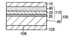
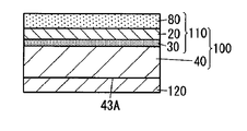
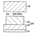
- FIGS. 2A to 2G are schematic cross-sectional views for explaining the step (A) of preparing the metal vapor-deposited film 100 with the conductive adhesive sheet.
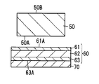
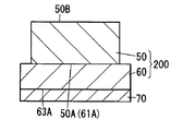
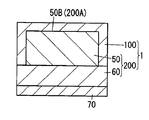
- FIGS. 4A and 4B are schematic cross-sectional views for explaining the step (B) of preparing the graphite film 200 with the conductive adhesive sheet.
- FIGS. 4A and 4B are schematic cross-sectional views for explaining the step (B) of preparing the graphite film 200 with the conductive adhesive sheet.
- 4C and 4D are schematic cross-sectional views for explaining the step (C) of laminating the metal vapor-deposited film 100 with a conductive adhesive sheet and the graphite film 200 with a conductive adhesive sheet.
- 2A to 2G and 4A to 4D the same components as those of the embodiment shown in FIG. 1A are denoted by the same reference numerals, and the description thereof is omitted.
- the graphite film 50 corresponds to the graphite layer 50
- the first conductive adhesive sheet 40 corresponds to the first conductive adhesive layer 40
- the second conductive adhesive sheet 60 corresponds to the second conductive adhesive. This corresponds to the adhesive layer 60.
- the manufacturing method of the graphite composite film 1 which concerns on 1st embodiment is the process (1A) which prepares the metal vapor deposition film 100 with a conductive adhesive sheet, the process (1B) which prepares the graphite film 200 with a conductive adhesive sheet, Including a step (1C) of laminating the metal vapor-deposited film 100 with the conductive adhesive sheet and the graphite film 200 with the conductive adhesive sheet, and the step (1A), the step (1B), and the step (1C) are performed in this order.
- the graphite composite film 1 with which electromagnetic wave shielding property is hard to deteriorate is obtained.
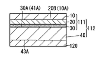
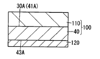
- the first conductive adhesive sheet 40 is disposed on the surface 30A of the first antirust treatment layer 30 of the first laminate 111 and laminated to prepare the second laminate 112 (hereinafter referred to as step (1a2). )).
- the protective film 10 of the second laminated body 112 is peeled off, and a second rust prevention treatment is applied to the second surface 20B of the metal layer 20 to form a second rust prevention treatment layer 80 (hereinafter, a process). (1a3)), the metal vapor deposition film 100 with a conductive adhesive sheet which has the metal vapor deposition film 110 and the 1st conductive adhesive sheet 40 is prepared.
- step (1A), the step (1B), and the step (1C) are performed in this order, but the present disclosure is not limited to this. As an example, step (1B), step (1A), and step (1C) may be performed in this order.
- Step (1A) In the step (1A), the step (1a1) of preparing the first laminate 111 by forming the metal layer 20 and the first antirust treatment layer 30, and the first laminate 111 and the first conductive adhesion The step (1a2) of preparing the second laminate 112 by laminating the sheet 40 and the step (1a3) of peeling off the protective film 10 to form the second antirust treatment layer 80 are performed in this order. . Thereby, the electroconductive adhesive sheet which has the metal vapor deposition film 110 and the 1st electroconductive adhesive sheet 40 which are the laminated bodies of the 1st antirust process layer 30, the metal layer 20, and the 2nd antirust process layer 80 The attached metal vapor deposition film 100 is prepared.
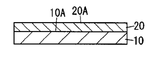
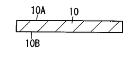
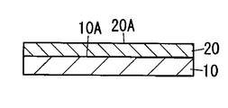
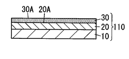
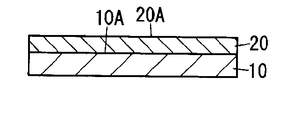
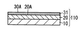
- a first metal is deposited on the first surface 10A of the protective film 10 shown in FIG. 2A to form a metal layer 20 as shown in FIG. 2B, and on the first surface 20A of the metal layer 20 A first rust prevention treatment layer 30 as shown in FIG. 2C is formed by applying the first rust prevention treatment.
- the first laminated body 111 having the protective film 10, the metal layer 20, and the first antirust treatment layer 30 shown in FIG. 2C is obtained.
- Examples of the raw material for the protective film 10 include polyester, polyethylene terephthalate, olefin resin, styrene resin, vinyl chloride resin, polycarbonate, acrylonitrile / styrene copolymer resin (AS resin), polyacrylonitrile, butadiene resin, acrylonitrile / butadiene / Styrene copolymer resin (ABS resin), acrylic resin, polyacetal, polyphenylene ether, phenol resin, epoxy resin, melamine resin, urea resin, polyimide, polysulfide, polyurethane, vinyl acetate resin, fluorine resin, aliphatic polyamide, synthetic rubber Aromatic polyamide, polyvinyl alcohol and the like can be used.
- AS resin acrylonitrile / styrene copolymer resin
- ABS resin acrylonitrile / butadiene copolymer resin
- acrylic resin polyacetal, polyphenylene ether, phenol resin, epoxy resin,
- the protective film 10 may further contain a flame retardant, an antistatic agent, an antioxidant, a metal deactivator, a plasticizer, a lubricant, and the like.
- the thickness of the protective film 10 is preferably 0.5 ⁇ m or more and 200 ⁇ m or less.
- the protective film 10 is preferably a release film.
- the release film for example, a film obtained by applying a release agent to the film can be used.
- the raw material of the film used for the release film include polyester, polyethylene terephthalate, olefin resin, styrene resin, vinyl chloride resin, polycarbonate, acrylonitrile / styrene copolymer resin (AS resin), polyacrylonitrile, butadiene resin, acrylonitrile. ⁇ Butadiene / styrene copolymer resin (ABS resin), acrylic resin, polyacetal, polyphenylene ether, phenol resin, epoxy resin, melamine resin, urea resin, polyimide, polysulfide, polyurethane, vinyl acetate resin, fluorine resin, aliphatic polyamide Synthetic rubber, aromatic polyamide, polyvinyl alcohol and the like can be used.
- the release agent for example, silicone can be used.
- the method for depositing the first metal is preferably a vacuum deposition method.
- the processing conditions of the vacuum deposition method may be appropriately adjusted according to the type of the first metal, the thickness of the metal layer 20, and the like.
- the following may be appropriately adjusted according to the raw material of the first rust prevention treatment layer 30.
- the first antirust treatment layer 30 is an organic film
- a method of applying the first antirust treatment to the first surface 20A of the metal layer 20 for example, the above-described organic film raw material is added to a solvent.
- the above-described organic film raw material is added to a solvent.
- examples thereof include a method of obtaining a rust prevention treatment liquid, coating the rust prevention treatment liquid on the first surface 20A of the metal layer 20, and drying the same.
- What is necessary is just to adjust suitably the addition amount of the raw material of an organic membrane
- a solvent what is necessary is just to adjust suitably according to the raw material of an organic membrane
- the rust preventive treatment liquid may contain other components as necessary.
- other components include carboxylic acid anhydrides.
- carboxylic acid anhydride acetic anhydride, succinic anhydride, maleic anhydride, propionic anhydride, and phthalic anhydride can be used.
- the coating method of the antirust treatment liquid is not particularly limited, and examples thereof include roller coating, roll coater coating, spin coater coating, curtain roll coater coating, slit coater coating, spray coating, and immersion coating. When drying a rust prevention liquid, you may heat as needed.
- the first rust prevention treatment layer 30 is a metal film
- the first rust prevention treatment layer 30 As a method of applying the first rust prevention treatment to the first surface 20A of the metal layer 20, the raw material of the metal film, the first rust prevention treatment layer 30
- electroplating method electroless-plating method
- physical vapor deposition method physical vapor deposition method
- physical vapor deposition include vacuum vapor deposition, ion plating, and sputtering.
- What is necessary is just to adjust the process conditions at the time of performing a rust prevention process suitably according to the raw material of a metal membrane
- the long protective film 10 is continuously fed to the production process for depositing the first metal, and the production process for depositing the first metal and the production for applying the first rust prevention treatment.
- the first laminate 111 may be continuously manufactured by passing the steps in this order.
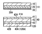
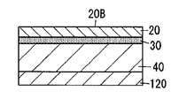
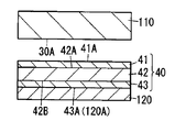
- Step (1a2) In the step (1a2), as shown in FIG. 2D, the first conductive adhesive sheet 40 is disposed and laminated on the surface 30A of the first laminate 111. At this time, as shown in FIG. 2D, the second release sheet 120 is attached to the surface 43 ⁇ / b> A of the first conductive adhesive sheet 40 in terms of excellent handleability. Through this step (1a2), the second laminate 112 having the first laminate 111 and the first conductive adhesive sheet 40 shown in FIG. 2E is obtained.
- FIG. 1st electroconductive adhesive sheet 40 As a manufacturing method of the 1st electroconductive adhesive sheet 40 to which the 2nd peeling sheet 120 shown to FIG. 2D was attached, the method including the following processes etc. are mentioned, for example. -The process of apply
- Examples of the method for applying the conductive adhesive include a method using a roll coater, a die coater and the like.
- the conductive adhesive contains a solvent
- the curing treatment conditions are such that the treatment temperature is preferably 15 ° C. or more and 50 ° C. or less, and the treatment time is preferably 48 hours or more and 168 hours or less.
- the configuration of the second release sheet 120 and the third release sheet is the same as that of the first release sheet 70.
- the surface 30A of the first laminate 111 and the surface 41A of the first conductive adhesive sheet 40 are:
- the 1st laminated body 111 and the 1st electroconductive adhesive sheet 40 are arrange
- the first laminated body 111 having a long shape and the first conductive adhesive sheet 40 having a long shape are fed out between a pair of rolls, and are sandwiched between a pair of rolls.
- the body 111 and the first conductive adhesive sheet 40 may be laminated by bringing them into surface contact.
- the second release sheet 120 is attached to the surface 43A of the first conductive adhesive sheet 40, but the present disclosure is not limited thereto, and the surface 43A of the first conductive adhesive sheet 40 is not limited thereto. In addition, the second release sheet 120 may not be attached.
- Step (1a3) In the step (1a3), as shown in FIG. 2F, the protective film 10 is peeled from the second laminate 112, and the second surface 20B of the metal layer 20 is subjected to the second rust prevention treatment, as shown in FIG. 2G. A second antirust treatment layer 80 is formed. Through this step (1a3), a metal vapor-deposited film 100 with a conductive adhesive sheet having the metal vapor-deposited film 110 and the first conductive adhesive sheet 40 shown in FIG. 2G is obtained.
- the method for applying the second antirust treatment can be the same as the method for applying the first antirust treatment in the step (1a1) of the present embodiment.
- the step (1A) includes the step (1a1), the step (1a2), and the step (1a3).
- the present disclosure is not limited to the order of the steps.
- the protection is performed after the step (1a1).
- a method of laminating the metal vapor-deposited film 110 and the first conductive adhesive sheet 40 after the metal vapor-deposited film 110 is produced by peeling the film 10 and forming the second antirust treatment layer 80 may be used.
- the protective film 10 is peeled off, and the laminate of the metal layer 20 and the first antirust treatment layer 30 and the first conductive adhesive sheet 40 are laminated, and then the second prevention. You may produce the metal vapor deposition film 100 with a conductive adhesive sheet by the method of forming the rust treatment layer 80, etc.
- Step (1B) In the step (1B), as shown in FIG. 4A, the second conductive adhesive sheet 60 is disposed and laminated on the first surface 50A of the graphite film 50 having the first surface 50A and the second surface 50B. At this time, as shown in FIG. 4A, the first release sheet 70 is attached to the surface 63 ⁇ / b> A of the second conductive adhesive sheet 60 in terms of excellent handleability. Through this step (1B), a graphite film 200 with a conductive adhesive sheet shown in FIG. 4B is obtained.
- the 1st electroconductivity to which the 2nd peeling sheet 120 shown to FIG. 2D mentioned above was attached was mentioned, for example.
- seat 40 is mentioned.
- the second conductive is performed so that the surface 61A of the second conductive adhesive sheet 60 faces upward.
- the adhesive sheet 60 is disposed.
- the method etc. which place the graphite film 50 cut by the predetermined dimension on the surface 61A of the 2nd conductive adhesive sheet 60 are mentioned.
- the cut graphite film 50 may be dimensioned so that the entire graphite film 50 is covered with the metal vapor-deposited film 100 with the conductive adhesive sheet and the graphite film 200 with the conductive adhesive sheet.
- the graphite composite film 1 is prevented from being broken due to delamination in the graphite layer 50, and graphite.
- the powder fall off of the layer 50 can be prevented.
- the second conductive adhesive sheet 60 is continuously fed to the laminate manufacturing process, and the cut graphite film 50 is separated from the surface 61A of the second conductive adhesive sheet 60 by a predetermined interval.
- the graphite film 200 with an electrically conductive adhesive sheet may be continuously manufactured by placing it continuously.
- the present disclosure is not limited to this, and the cut graphite film 50 is laminated on the surface 61A of the second conductive adhesive sheet 60.
- the present disclosure is not limited to this, and is long.
- Each of the long graphite film 50 and the long second conductive adhesive sheet 60 is continuously fed between a pair of rolls, and sandwiched between the pair of rolls, and then the graphite film 50 and the second conductive adhesive sheet 60.
- Laminate may be laminated by surface contact.
- Step (1C) In the step (1C), as shown in FIG. 4C, the metal vapor-deposited film 100 with the conductive adhesive sheet and the graphite film 200 with the conductive adhesive sheet are formed on the surface 43A of the first conductive adhesive sheet 40 and the first of the graphite film 50. Laminate so that the two surfaces 50B overlap. At this time, as shown in FIG. 4C, the second release sheet 120 is peeled off, and the first release sheet 70 remains attached in view of excellent handleability of the graphite composite film 1. Through this step (1C), a graphite composite film 1 shown in FIG. 4D is obtained.
- the surface 200A on the side where the graphite film 50 is disposed is upward.
- the graphite film 200 with a conductive adhesive sheet is arranged so as to be. Then, the method etc. which put the metal vapor deposition film 100 with a conductive adhesive sheet on the surface 200A of the graphite film 200 with a conductive adhesive sheet so that the graphite film 50 whole may be covered are mentioned.
- the long metal deposited film with a conductive adhesive sheet 100 and the long conductive graphite film with a conductive adhesive sheet 200 are fed out between a pair of rolls. Then, it is sandwiched between a pair of rolls, laminated by bringing the metal vapor-deposited film 100 with a conductive adhesive sheet and the graphite film 200 with a conductive adhesive sheet into surface contact, and cut into a required size, whereby the graphite composite film 1 is obtained. You may manufacture continuously.
- the process (1A), the process (1B), and the process (1C) are included, but the present disclosure is not limited to the stacking order, and the following methods are exemplified.
- the protective film 10 is peeled off and the second rust prevention treatment is performed.
- the method of manufacturing the graphite composite film 1 by forming the layer 80 is mentioned.
- FIGS. 3A to 3G are schematic cross-sectional views for explaining a part of the manufacturing method of the graphite composite film 1 according to the second embodiment of the present disclosure. Specifically, FIGS. 3A to 3G are schematic cross-sectional views for explaining the step (1A) of preparing the metal vapor-deposited film 100 with the conductive adhesive sheet.
- FIG. 4A to 4D are schematic cross-sectional views for explaining a part of the method for producing the graphite composite film 1 according to the second embodiment of the present invention.
- FIG. 4A and FIG. 4B are schematic cross-sectional views for explaining a step (1B) of preparing a graphite film 200 with a conductive adhesive sheet.
- 4C and 4D are schematic cross-sectional views for explaining the step (1C) of laminating the metal vapor-deposited film 100 with the conductive adhesive sheet and the graphite film 200 with the conductive adhesive sheet.
- 3A to 3G and FIGS. 4A to 4D the same components as those of the embodiment shown in FIG. 1A are denoted by the same reference numerals, and description thereof is omitted.
- the graphite film 50 corresponds to the graphite layer 50
- the first conductive adhesive sheet 40 corresponds to the first conductive adhesive layer 40
- the second conductive adhesive sheet 60 corresponds to the second conductive adhesive. This corresponds to the adhesive layer 60.
- the manufacturing method of the graphite composite film 1 which concerns on 2nd embodiment is the process (1A) which prepares the metal vapor deposition film 100 with a conductive adhesive sheet, the process (1B) which prepares the graphite film 200 with a conductive adhesive sheet, Including a step (1C) of laminating the metal vapor-deposited film 100 with the conductive adhesive sheet and the graphite film 200 with the conductive adhesive sheet, and the step (1A), the step (1B), and the step (1C) are performed in this order.
- the graphite composite film 1 with which electromagnetic wave shielding property is hard to deteriorate is obtained.
- the antirust treatment layer 80 and the metal layer 20 containing the first metal are formed (hereinafter, step (1a1)).
- the first surface 20A of the metal layer 20 is subjected to a rust prevention treatment to form a first rust prevention treatment layer 30 to prepare a laminate 113 of the protective film 10 and the metal vapor deposition film 110 (hereinafter, step (1a2)). ).
- step (1a3) After the first conductive adhesive sheet 40 is disposed and laminated on the surface 30A of the first antirust treatment layer 30 of the laminate 113, the protective film 10 is peeled off (hereinafter referred to as step (1a3)), The metal vapor deposition film 100 with a conductive adhesive sheet which has the metal vapor deposition film 110 and the 1st conductive adhesive sheet 40 is prepared.
- step (1A), the step (1B), and the step (1C) are performed in this order, but the present disclosure is not limited to this. As an example, step (1B), step (1A), and step (1C) may be performed in this order.
- process (1B) and process (1C) in this embodiment are the processes similar to the process (1B) and process (1C) in 1st embodiment, description is abbreviate
- Step (1A) In the step (1A), a step (1a1) of forming the second antirust treatment layer 80 and the metal layer 20, a step of forming the first antirust treatment layer 30 and preparing the laminate 113, and (1a2) Then, after laminating the laminate 113 and the first conductive adhesive sheet 40, the step (1a3) of peeling the protective film 10 is performed in this order. Thereby, the electroconductive adhesive sheet which has the metal vapor deposition film 110 and the 1st electroconductive adhesive sheet 40 which are the laminated bodies of the 1st antirust process layer 30, the metal layer 20, and the 2nd antirust process layer 80 The attached metal vapor deposition film 100 is prepared.
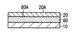
- a second metal is vapor-deposited on the first surface 10A of the protective film 10 shown in FIG. 3A to form a second antirust treatment layer 80 as shown in FIG. 3B.
- a 1st metal is vapor-deposited on the surface 80A of the 2nd antirust process layer 80, and the metal layer 20 as shown to FIG. 3C is formed.
- the protective film 10 used in the present embodiment may be the same as the protective film 10 used in the first embodiment.
- the method for depositing the first metal is preferably a vacuum deposition method.
- the processing conditions of the vacuum deposition method may be appropriately adjusted according to the type of the first metal, the thickness of the metal layer 20, and the like.
- the method for vapor-depositing the second metal may be appropriately adjusted according to the type of the second metal, the thickness of the second antirust treatment layer 80, etc.
- electroplating, electroless plating, physical Examples thereof include vapor deposition and chemical vapor deposition.
- physical vapor deposition include vacuum vapor deposition, ion plating, and sputtering.
- the method for depositing the second metal is preferably a vacuum deposition method.
- the processing conditions of the vacuum deposition method may be appropriately adjusted according to the type of the second metal, the thickness of the second antirust treatment layer 80, and the like.
- the long protective film 10 is continuously fed to the manufacturing process for depositing the second metal, the manufacturing process for depositing the second metal, and the manufacturing process for depositing the first metal.
- the second antirust treatment layer 80 and the metal layer 20 may be manufactured continuously.
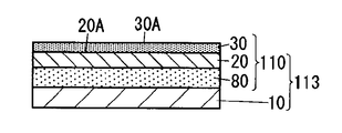
- step (1a2) the first surface 20A of the metal layer 20 is subjected to a rust prevention treatment to form a first rust prevention treatment layer 30 as shown in FIG. 3D.
- a laminate 113 having the protective film 10 and the metal vapor deposition film 110 shown in FIG. 3D is obtained.
- the method of applying a rust prevention treatment to the first surface 20A of the metal layer 20 in the step (1a2) of the present embodiment uses the same method as the method of applying the first rust prevention treatment in the step (1a1) of the first embodiment. be able to.
- Process (1a2) can be made to be continuous with the process (1a1) by, for example, passing the continuous manufacturing process (1a1) through the process of forming the first antirust treatment layer.
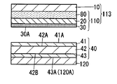
- the first conductive adhesive sheet 40 is disposed and laminated on the surface 30A of the first antirust treatment layer 30 of the laminate 113.
- the second release sheet 120 is attached to the surface 43 ⁇ / b> A of the first conductive adhesive sheet 40 in terms of excellent handleability.
- the protective film 10 is peeled, and the metal vapor deposition film 100 with a conductive adhesive sheet having the metal vapor deposition film 110 and the first conductive adhesive sheet 40 shown in FIG. 3G is obtained.
- the manufacturing method of the first conductive adhesive sheet 40 shown in FIG. 2D may be the same.
- the laminate 113 is laminated so that the surface 30 ⁇ / b> A of the laminate 113 and the surface 41 ⁇ / b> A of the first conductive adhesive sheet 40 face each other.
- the body 113 and the first conductive adhesive sheet 40 are disposed. Then, the method of making the surface 30A of the laminated body 113 and the surface 41A of the 1st electroconductive adhesive sheet 40 contact and pressurize, etc. are mentioned.
- the laminate 113 and the long first conductive adhesive sheet 40 are fed out between a pair of rolls and sandwiched between the pair of rolls, and the laminate 113 and the first conductive adhesive sheet.
- Lamination may be performed by bringing 40 into surface contact.
- the second release sheet 120 is attached to the surface 43A of the first conductive adhesive sheet 40, but the present invention is not limited to this, and the surface 43A of the first conductive adhesive sheet 40. In addition, the second release sheet 120 may not be attached.
- the step (1A) includes the step (1a1), the step (1a2), and the step (1a3).
- the present invention is not limited to this step order.
- the step (1a1) and the step (1a2) After the protective film 10 is peeled off from the laminate 113, the metal vapor-deposited film 110 is produced, and then the metal vapor-deposited film 110 and the first conductive adhesive sheet 40 are laminated.
- the 1st antirust process layer 30 is formed by a process (1a2), Then, the metal vapor deposition film 110 and the 1st electroconductive adhesive sheet 40 are made. You may produce the metal vapor deposition film 100 with an electroconductive adhesive sheet by the method of laminating.
- this indication is not limited to this lamination order, and the following methods are mentioned.
- the laminate 113, the first conductive adhesive sheet 40, the graphite film 50, and the second conductive adhesive sheet 60 are laminated at the same time, and then the protective film 10 is peeled to produce the graphite composite film 1.
- a method is mentioned.
- a laminated film is obtained by laminating the first conductive adhesive sheet 40, the graphite film 50, and the second conductive adhesive sheet 60, and the obtained laminated film and the metal vapor deposited film 110 are laminated. Then, a method for producing the graphite composite film 1 can be mentioned.
- Step (1A)] (Process (1a1)
- a polyester film (“CX40” manufactured by Toray Industries, Inc., main raw material: PET, thickness: 6 ⁇ m) was prepared.
- a metal layer 20 (thickness: 1 ⁇ m) as shown in FIG. 2B is deposited on the first surface 10A of the protective film 10 by vacuum deposition using copper (oxygen-free copper made by Hitachi Materials) as the first metal. ) was formed.
- a rust preventive agent (C-Iguard “GW-172P” manufactured by Toei Kasei Co., Ltd.) is roller-coated on the first surface 20A of the metal layer 20, dried, and the first rust preventive treatment as shown in FIG. 2C.
- Layer 30 (thickness: 4 nm) was formed. This obtained the 1st laminated body 111 shown to FIG. 2C.
- the first laminate 111 and the first conductive adhesive sheet so that the surface 30A of the first laminate 111 and the surface 41A of the first conductive adhesive sheet 40 face each other. 40 was placed, and the surface 30A of the first laminate 111 and the surface 41A of the first conductive adhesive sheet 40 were brought into close contact with each other. This obtained the 2nd laminated body 112 shown to FIG. 2E.
- Step (1B) As the second conductive adhesive sheet 60 to which the first release sheet 70 is attached, a sheet obtained by peeling the release sheet from one surface 61A of the conductive double-sided adhesive sheet that is the same product as the first conductive adhesive sheet 40 Prepared.
- As the graphite film 50 a graphite film having a size cut of 10 cm ⁇ 12 cm (“PGS (registered trademark) graphite sheet manufactured by Panasonic Corporation, thickness: 25 ⁇ m)” was prepared.
- the second conductive adhesive sheet 60 is arranged so that the surface 61A of the second conductive adhesive sheet 60 faces upward, and the graphite film 50 is placed on the surface of the second conductive adhesive sheet 60. Placed on 61A. Thereby, the graphite film 200 with a conductive adhesive sheet shown in FIG. 4B was obtained.
- Step (1C) As shown in FIG. 4C, the graphite film 200 with the conductive adhesive sheet is disposed so that the surface 200A on the side on which the graphite film 50 is disposed faces upward, and the metal with the conductive adhesive sheet is covered so as to cover the entire graphite film 50.
- the deposited film 100 was placed on the surface 200A of the graphite film 200 with a conductive adhesive sheet and cut into a size of 10 cm ⁇ 12 cm. Thereby, the graphite composite film 1 shown in FIG. 4D was obtained.
- Example 2 (Process (1a1)) As the protective film 10, a polyester film (“CX40” manufactured by Toray Industries, Inc., main raw material: PET, thickness: 6 ⁇ m) was prepared. A second antirust treatment layer 80 (see FIG. 3B) is deposited on the first surface 10A of the protective film 10 by vacuum deposition using nickel (electrolytic nickel manufactured by Sumitomo Metal Mining) as the second metal. (Thickness: 40 nm) was formed. Next, the metal layer 20 as shown in FIG. 3C is deposited on the surface 80A of the second antirust treatment layer 80 by vacuum deposition using copper (oxygen-free copper made by Hitachi Materials) as the first metal. (Thickness: 1 ⁇ m) was formed.
- nickel electrolytic nickel manufactured by Sumitomo Metal Mining
- a first antirust treatment layer 30 as shown in FIG. 3D is coated with a rust preventive agent (C eye guard “GW-172P” manufactured by Toei Kasei Co., Ltd.) on the first surface 20A of the metal layer 20 and dried. (Thickness: 4 nm) was formed. This obtained the laminated body 113 shown to FIG. 3D.
- a rust preventive agent C eye guard “GW-172P” manufactured by Toei Kasei Co., Ltd.
- the laminate 113 and the first conductive adhesive sheet 40 are arranged so that the surface 30A of the laminate 113 and the surface 41A of the first conductive adhesive sheet 40 face each other.
- the surface 30A of the body 113 and the surface 41A of the first conductive adhesive sheet 40 were brought into close contact with each other by contact pressure.
- the polyester film as the protective film 10 was pressed against a peeling roller and peeled off. Thereby, the metal vapor deposition film 100 with a conductive adhesive sheet shown to FIG. 3G was obtained.
- Step (1B) As the second conductive adhesive sheet 60 to which the first release sheet 70 is attached, a sheet obtained by peeling the release sheet from one surface 61A of the conductive double-sided adhesive sheet that is the same product as the first conductive adhesive sheet 40 Prepared.
- As the graphite film 50 a graphite film having a size cut of 10 cm ⁇ 12 cm (“PGS (registered trademark) graphite sheet manufactured by Panasonic Corporation, thickness: 25 ⁇ m)” was prepared.
- the second conductive adhesive sheet 60 is arranged so that the surface 61A of the second conductive adhesive sheet 60 faces upward, and the graphite film 50 is placed on the surface of the second conductive adhesive sheet 60. Placed on 61A. Thereby, the graphite film 200 with a conductive adhesive sheet shown in FIG. 4B was obtained.
- Step (1C) As shown in FIG. 4C, the graphite film 200 with the conductive adhesive sheet is disposed so that the surface 200A on the side on which the graphite film 50 is disposed faces upward, and the metal with the conductive adhesive sheet is covered so as to cover the entire graphite film 50.
- the deposited film 100 was placed on the surface 200A of the graphite film 200 with a conductive adhesive sheet and cut into a size of 10 cm ⁇ 12 cm. Thereby, the graphite composite film 1 shown in FIG. 4D was obtained.
- a rust preventive agent (C eye guard “GW-172P” manufactured by Toei Kasei Co., Ltd.) is roller-coated on the first surface 20A of the metal layer 20, dried, and the rust preventive treatment layer 30 (as shown in FIG. 5C) (Thickness: 4 nm). Thereby, the metal vapor deposition film 110 shown in FIG. 5C was obtained.
- the metal vapor-deposited film 110 and the first conductive adhesive sheet 40 are arranged so that the surface 30A of the metal vapor-deposited film 110 and the surface 41A of the first conductive adhesive sheet 40 face each other.
- the surface 30A of the metal vapor-deposited film 110 and the surface 41A of the first conductive adhesive sheet 40 were brought into close contact with each other. Thereby, the metal vapor deposition film 100 with a conductive adhesive sheet shown to FIG. 5E was obtained.
- Step (1B) As the second conductive adhesive sheet 60 to which the first release sheet 70 is attached, a sheet obtained by peeling the release sheet from one surface 61A of the conductive double-sided adhesive sheet that is the same product as the first conductive adhesive sheet 40 Prepared.
- As the graphite film 50 a graphite film having a size cut of 10 cm ⁇ 12 cm (“PGS (registered trademark) graphite sheet manufactured by Panasonic Corporation, thickness: 25 ⁇ m)” was prepared.
- the second conductive adhesive sheet 60 is arranged so that the surface 61A of the second conductive adhesive sheet 60 faces upward, and the graphite film 50 is placed on the surface of the second conductive adhesive sheet 60. Placed on 61A. Thereby, the graphite film 200 with a conductive adhesive sheet shown in FIG. 4B was obtained.
- Step (1C) As shown in FIG. 4C, the graphite film 200 with the conductive adhesive sheet is disposed so that the surface 200A on the side on which the graphite film 50 is disposed faces upward, and the metal with the conductive adhesive sheet is covered so as to cover the entire graphite film 50.
- the deposited film 100 was placed on the surface 200A of the graphite film 200 with a conductive adhesive sheet and cut into a size of 10 cm ⁇ 12 cm. Thereby, the graphite composite film 1 shown in FIG. 4D was obtained.
- the first release sheet 70 was peeled from the obtained graphite composite film 1 and the surface 1A of the graphite composite film 1 and the surface of the adherend were brought into close contact with each other to obtain a sample 1.
- This sample 1 was subjected to an exposure treatment under exposure conditions of 40 ° C. and 95% RH for 250 hours, and sample 2 was obtained for each of the graphite composite films 1 of Examples 1-2 and Comparative Examples 1-2.
- Sample 3 was obtained in the same manner as Sample 2, except that the exposure treatment was set to 105 ° C.
- Table 1 shows the measurement results of the electric field shielding performance and magnetic field shielding performance of Samples 1, 2, and 3.
- FIG. 6A is a schematic cross-sectional view of the main body of the graphite composite film 1 according to this embodiment.
- FIG. 6B is a schematic cross-sectional view of the end portion of the graphite composite film 1.
- the graphite composite film 1 includes a second conductive adhesive layer 60, a graphite layer 50, a first conductive adhesive layer 40, a metal layer 20, and a protective film. 10 and the antirust treatment layer 31.
- the metal layer 20 includes a first metal.
- the second conductive adhesive layer 60, the graphite layer 50, the first conductive adhesive layer 40, the metal layer 20, and the protective film 10 are laminated in this order.
- the antirust treatment layer 31 is interposed between the first conductive adhesive layer 40 and the metal layer 20.
- the first release sheet 70 is attached to the surface 60 ⁇ / b> A of the second conductive adhesive layer 60.
- the graphite composite film 1 Since the graphite composite film 1 has such a configuration, it is possible to simultaneously realize heat countermeasures and electromagnetic noise countermeasures for electromagnetic devices by simply attaching them to the adherend. That is, since the graphite layer 50 having excellent thermal conductivity is provided, the heat of the adherend can be dissipated in the plane direction of the graphite composite film 1 to lower the temperature of the adherend.
- the plane direction refers to a direction perpendicular to the thickness direction of the graphite layer 50.
- the electromagnetic waves which hit the metal layer 20 can be reflected. This is presumed that when an electromagnetic wave hits the metal layer 20, an eddy current is generated in the metal layer 20 by electromagnetic induction, and this reflects the electromagnetic wave.
- the adherend is conductive, the metal layer 20 is electrically connected to the adherend and grounded, so eddy currents generated in the metal layer 20 are released (grounded) to the adherend. And more excellent electromagnetic shielding properties.
- the rust prevention treatment layer 31 is interposed between the first conductive adhesive layer 40 and the metal layer 20, the first surface 20A of the metal layer 20 on the side where the rust prevention treatment layer 31 is disposed. Is less likely to discolor (hereinafter referred to as corrosion) and the electromagnetic shielding properties are less likely to deteriorate. This is because the antirust treatment layer 31 suppresses the progress of the corrosion of the metal layer 20 so that the sheet resistance of the metal layer 20 is less likely to increase with time, and the generated eddy current energy is less likely to be converted into thermal energy. It is presumed to be.
- the end face 50E of the graphite layer 50 is not exposed as shown in FIG. 6B. That is, the end surface 50 ⁇ / b> E of the graphite layer 50 is covered with the first conductive adhesive layer 40 and the second conductive adhesive layer 60. As a result, it is possible to prevent the graphite composite film 1 from being broken due to delamination in the graphite layer 50 and at the same time to prevent the graphite layer 50 from falling off.
- the thickness of the graphite composite film 1 is preferably 15 ⁇ m or more and 800 ⁇ m or less.
- the thickness of the graphite composite film 1 can be measured based on an image obtained by observing a cross section of the graphite composite film 1 with a scanning electron microscope (SEM).
- SEM scanning electron microscope
- the thickness of each layer constituting the following graphite composite film 1 can also be measured in the same manner.
- the graphite composite film 1 can be used by, for example, peeling the first release sheet 70 from the graphite composite film 1 immediately before use and attaching it to an adherend.
- adherend include an electronic component arranged inside a housing of an electronic device.
- the electronic components include a rear chassis of a liquid crystal unit, an LED substrate having a light emitting diode (LED) light source used for a backlight of a liquid crystal image display device, a power amplifier, a large scale integrated circuit (LSI), and the like. It is done.
- the first release sheet 70 a paper, a resin film, a laminated paper obtained by laminating paper and a resin film, a paper that has been subjected to a sealing treatment with clay, polyvinyl alcohol, or the like on one or both sides, a silicone resin or the like What gave the peeling process etc.
- the paper include craft paper, glassine paper, and high-quality paper.
- the resin film include papers such as polyethylene, polypropylene (OPP, CPP), and polyethylene terephthalate (PET).
- the second conductive adhesive layer 60, the graphite layer 50, the first conductive adhesive layer 40, the antirust treatment layer 31, the metal layer 20, and the protective film 10 are in this order. It has a stacked configuration.
- the present disclosure is not limited thereto, as long as the graphite layer 50, the first conductive adhesive layer 40, the rust prevention treatment layer 31, the metal layer 20, and the protective film 10 are arranged in this order, Between these layers, the layer which does not inhibit the effect of this invention may be laminated
- the end face 50E of the graphite layer 50 is covered with the first conductive adhesive layer 40 and the second conductive adhesive layer 60.
- the present disclosure is not limited thereto, and the end face of the graphite layer 50 is not limited thereto. 50E may be exposed.
- the end surface of the metal layer 20 is exposed, but the present disclosure is not limited to this, and the end surface of the metal layer 20 may be covered with the protective film 10. Good.
- the end surface of the metal layer 20 is less likely to be corroded, and the electromagnetic wave shielding properties of the graphite composite film 1 are less likely to deteriorate.
- the graphite composite film 1 includes a protective film 10. Thereby, while progress of the oxidation of the 2nd surface 20B by the side of the protective film 10 of the metal layer 20 arrange
- Examples of the raw material for the protective film 10 include polyester, polyethylene terephthalate, olefin resin, styrene resin, vinyl chloride resin, polycarbonate, acrylonitrile / styrene copolymer resin (AS resin), polyacrylonitrile, butadiene resin, acrylonitrile / butadiene / Styrene copolymer resin (ABS resin), acrylic resin, polyacetal, polyphenylene ether, phenol resin, epoxy resin, melamine resin, urea resin, polyimide, polysulfide, polyurethane, vinyl acetate resin, fluorine resin, aliphatic polyamide, synthetic rubber Aromatic polyamide, polyvinyl alcohol and the like can be used.
- AS resin acrylonitrile / styrene copolymer resin
- ABS resin acrylonitrile / butadiene copolymer resin
- acrylic resin polyacetal, polyphenylene ether, phenol resin, epoxy resin,
- the protective film 10 may further contain a flame retardant, an antistatic agent, an antioxidant, a metal deactivator, a plasticizer, a lubricant, and the like.
- the thickness of the protective film 10 is preferably 0.5 ⁇ m or more and 200 ⁇ m or less.
- the surface shape of the protective film 10 viewed from the thickness direction T of the graphite composite film 1 is solid. That is, when viewed from the thickness direction T of the protective film 10, the protective film 10 is provided in the entire region of the surface of the graphite composite film 1 without a gap, and the metal layer 20 is not exposed.
- the graphite composite film 1 includes a metal layer 20. Thereby, the graphite composite film 1 has electromagnetic wave shielding properties.
- the metal layer 20 includes a first metal. What is necessary is just to select suitably as a 1st metal according to the raw material of the graphite composite film 1, for example, silver, copper, gold
- the first metal is preferably a raw material having a low volume resistivity among the raw materials of the graphite composite film 1 from the viewpoint of improving the electromagnetic wave shielding property of the graphite composite film 1 and is copper. Is more preferable.
- the thickness of the metal layer 20 is preferably 0.10 ⁇ m or more and 5.00 ⁇ m or less, more preferably 0.50 ⁇ m or more and 2.00 ⁇ m or less.
- the surface shape viewed from the thickness direction T of the metal layer 20 is a solid shape, but the present disclosure is not limited to this. Examples thereof may further include a mesh shape, a wire shape, and the like.
- the graphite composite film 1 includes a rust prevention treatment layer 31.
- the antirust treatment layer 31 is interposed between the first conductive adhesive layer 40 and the metal layer 20.
- the first surface 20A of the metal layer 20 is unlikely to corrode.
- the rust-proofing layer 31 mainly prevents moisture and oxygen components contained in the first conductive adhesive layer 40 from reaching the surface of the metal layer 20, This is presumably because an electrochemical reaction with a component in one conductive adhesive layer 40 hardly proceeds.
- the rust prevention treatment layer 31 for example, an organic film, a metal film or the like can be used.
- the organic film may be appropriately adjusted according to the raw material of the metal layer 20, and examples thereof include a benzotriazole film, a triazineamine film, a mercaptobenzimidazole film, a thiodipropionic acid ester film, and a benzimidazole film.
- the organic film is preferably a benzotriazole film. If the organic film is a benzotriazole film, the metal layer 20 made of copper is less likely to corrode.
- the benzotriazole film is presumed to be a polymer complex film mainly composed of copper ions and a benzotriazole anion or a benzotriazole derivative anion.
- a raw material for the benzotriazole film for example, benzotriazole, a benzotriazole derivative, or the like can be used.
- the benzotriazole derivatives include benzotriazole, 2- (5-methyl-2-hydroxyphenyl) benzotriazole, 1,2,3-benzotriazole, 2- [2-hydroxy-3,5-bis ( ⁇ , ⁇ -dimethylbenzyl) phenyl] -2H-benzotriazole and the like can be used.
- a raw material for the triazine amine film for example, 2,4-diamino-6- [2'-methylimidazolyl- (1 ')]-ethyl-s-triazine can be used.
- a raw material for the mercaptobenzimidazole film for example, 2-mercaptobenzimidazole, 2-mercapto-5-methylbenzimidazole, 2-mercapto-5-methoxybenzimidazole and the like can be used.
- a raw material for the thiodipropionate film for example, distearyl-3, 3'-thiodipropionate, dilauryl-3,3'-thiodipropionate, or the like can be used.
- benzimidazole film for example, 2-methylbenzimidazole, 5-methylbenzimidazole, 1-hydroxy-5-methoxy-2-methylbenzimidazole-3-oxide, 2-aminobenzimidazole, etc. may be used. it can.
- the metal film As a raw material for the metal film, for example, pure metals such as zinc, nickel, chromium, titanium, aluminum, gold, silver, palladium, and alloys containing these pure metals can be used.
- the metal film when the first metal is copper, the metal film includes at least one second metal selected from the group consisting of zinc, nickel, chromium, titanium, aluminum, gold, silver, palladium, and alloys thereof. It is preferable to include. If the metal film is made of the second metal, the metal layer 20 made of copper is unlikely to corrode.
- the thickness T30 of the rust prevention treatment layer 31 is preferably equal to or less than the thickness T20 of the metal layer 20. Thereby, the flexibility of the graphite composite film 1 can be ensured, and at the same time, the weight of the graphite composite film 1 can be reduced.
- the thickness T30 of the rust prevention layer 31 is preferably 0.002 ⁇ m or more and 0.100 ⁇ m or less, and more preferably 0.002 ⁇ m or more and 0.040 ⁇ m or less.
- the surface shape of the antirust treatment layer 31 viewed from the thickness direction T of the graphite composite film 1 is solid.
- the graphite composite film 1 includes a first conductive adhesive layer 40.
- the antirust treatment layer 31 and the graphite layer 50 can be bonded and fixed and simultaneously electrically connected.
- the first conductive adhesive layer 40 has a configuration in which a first adhesive layer 41, a first metal substrate 42, and a second adhesive layer 43 are laminated in this order. Since the 1st conductive adhesive layer 40 contains the 1st metal base material 42, the 1st conductive adhesive layer 40 is excellent in electroconductivity.
- the thickness of the first conductive adhesive layer 40 is preferably 2 ⁇ m or more and 300 ⁇ m or less.
- the surface shape of the first conductive adhesive layer 40 viewed from the thickness direction T of the graphite composite film 1 is solid.
- the first adhesive layer 41 is made of a conductive adhesive having conductivity and adhesiveness.
- a conductive adhesive for example, a polymer and a conductive filler are contained, and a crosslinking agent, an additive, and a solvent may be further contained as necessary.
- the polymer an acrylic polymer, a rubber polymer, a silicone polymer, a urethane polymer, or the like can be used. Among these, it is preferable to use an acrylic polymer and a rubber polymer in that they are not easily peeled off due to the influence of heat even when the graphite composite film 1 is attached to a heat generating material.
- acrylic polymer those obtained by polymerizing vinyl monomers such as (meth) acrylic monomers can be used.
- a metal filler for example, a metal filler, a carbon filler, a metal composite filler, a metal oxide filler, a potassium titanate filler, or the like can be used.
- the raw material for the metal filler include silver, nickel, copper, tin, aluminum, and stainless steel.
- ketjen black, acetylene black, graphite or the like can be used.
- As a raw material for the metal composite filler aluminum coated glass, nickel coated glass, silver coated glass, nickel coated carbon, or the like can be used.
- antimony-doped tin oxide, tin-doped indium oxide, aluminum-doped zinc oxide, or the like can be used.
- the shape of the conductive filler is not particularly limited, and examples thereof include powder, flakes, and fibers.
- the crosslinking agent an isocyanate crosslinking agent, an epoxy crosslinking agent, a chelate crosslinking agent, an aziridine crosslinking agent, or the like can be used.
- a tackifier resin can be used for the purpose of further improving the adhesive strength of the first adhesive layer 41.
- the tackifying resin examples include rosin resin, terpene resin, aliphatic (C5) or aromatic (C9) petroleum resin, styrene resin, phenol resin, xylene resin, methacrylic resin, and the like. be able to.
- the thickness of the 1st adhesion layer 41 becomes like this. Preferably they are 0.2 micrometer or more and 50 micrometers or less, More preferably, they are 2 micrometers or more and 20 micrometers or less.
- the raw material of the first metal base material 42 for example, gold, silver, copper, aluminum, nickel, iron, tin, or an alloy thereof can be used.
- the raw material of the first metal base material 42 is preferably aluminum or copper in terms of flexibility, thermal conductivity, etc., and aluminum in terms of corrosion being difficult to proceed due to metal passivation. Is more preferable.
- the metal substrate made of aluminum a hard aluminum substrate made of hard aluminum or a soft aluminum substrate made of soft aluminum can be used.
- the hard aluminum substrate is made of an aluminum foil obtained by rolling aluminum.
- a soft aluminum base material consists of aluminum foil obtained by rolling aluminum and annealing.
- As the metal substrate made of copper for example, a substrate made of electrolytic copper or a substrate made of rolled copper can be used.
- the thickness of the first metal substrate 42 is preferably 200 ⁇ m or less, more preferably 100 ⁇ m or less.
- the second adhesive layer 43 has conductivity and adhesiveness, and contains, for example, a polymer and a conductive filler.
- the second adhesive layer 43 has the same configuration as the first adhesive layer 41.
- the first conductive adhesive layer 40 includes a first adhesive layer 41, a first metal substrate 42, and a second adhesive layer 43 that are laminated in this order.
- the present disclosure is not limited thereto.
- the first conductive adhesive layer 40 may be a single layer made of a conductive resin.
- the second adhesive layer 43 has the same configuration as that of the first adhesive layer 41.
- the present disclosure is not limited to this, and the first adhesive layer 43 can be provided as long as it has conductivity and adhesiveness. A configuration different from that of the layer 41 may be used.
- the graphite composite film 1 includes a graphite layer 50. Thereby, the heat
- the graphite layer 50 has excellent electrical conductivity and thermal conductivity in the plane direction.
- a raw material of the graphite layer 50 for example, a carbon layered crystal graphite (graphite); a graphite intercalation compound (Graphite Intercalation Compound) formed by using graphite as a base material and chemical species invading between the layers is used.
- the chemical species include potassium, lithium, bromine, nitric acid, iron (III) chloride, tungsten hexachloride, and arsenic pentafluoride.
- the graphite layer 50 may be a laminate of one or more graphite films, for example.
- the graphite film for example, a thermally decomposable graphite sheet generated by baking a polymer film at a high temperature, an expanded graphite sheet generated by an expanded graphite method, or the like can be used. Above all, use a pyrolytic graphite sheet produced by baking a polymer film at a high temperature as a graphite film because of its high thermal conductivity, light weight, flexibility, and ease of processing. Is preferred.
- a heat-resistant aromatic polymer such as polyimide, polyamide, and polyamideimide can be used.
- the temperature for firing the polymer film is preferably 2600 ° C. or higher and 3000 ° C. or lower.
- the expanded graphite method is a method in which natural graphite lead is treated with a strong acid such as sulfuric acid to form an intercalation compound, and the expanded graphite produced when heated and expanded is rolled into a sheet form.
- the thickness of the graphite film is preferably 10 ⁇ m or more and 100 ⁇ m or less.
- the thermal conductivity of the pyrolytic graphite sheet is preferably 700 W / (m ⁇ K) to 1950 W / (m ⁇ K) in the ab plane direction, and preferably 8 W / m ⁇ K to 15 W / c in the c-axis direction. (M ⁇ K) or less.
- Density of pyrolytic graphite sheet is preferably 0.85 g / cm 3 or more 2.13 g / cm 3 or less.
- PPS registered trademark
- the thickness of the graphite layer 50 is preferably 5 ⁇ m or more and 500 ⁇ m or less, more preferably 10 ⁇ m or more and 200 ⁇ m or less.
- the surface shape of the graphite layer 50 viewed from the thickness direction T of the graphite composite film 1 is solid.
- the graphite composite film 1 includes a second conductive adhesive layer 60. Thereby, the graphite composite film 1 can be adhered to the adherend, and the excellent heat dissipation of the graphite composite film 1 can be easily developed, and at the same time, the graphite layer 50 and the adherend can be electrically connected. it can. Thus, since the metal layer 20 and the adherend are electrically connected, the electromagnetic wave shielding property of the graphite composite film 1 is more excellent when the adherend has conductivity.
- the second conductive adhesive layer 60 is formed by laminating a third adhesive layer 61, a second metal substrate 62, and a fourth adhesive layer 63 in this order.
- the configuration of the second conductive adhesive layer 60 is the same as that of the first conductive adhesive layer 40.
- the second conductive adhesive layer 60 is formed by laminating a third adhesive layer 61, a second metal substrate 62, and a fourth adhesive layer 63 in this order.
- the present disclosure is not limited to this.
- the second conductive adhesive layer 60 may be a single layer made of a conductive resin.
- the configuration of the second conductive adhesive layer 60 is the same as that of the first conductive adhesive layer 40.
- the present disclosure is not limited to this, and the conductivity and tackiness are improved. If it exists, the structure different from the 1st electroconductive contact bonding layer 40 may be sufficient.
- FIGS. 7A to 7E are schematic cross-sectional views for explaining the step (2A) of preparing the metal vapor-deposited film 100 with the conductive adhesive sheet.
- FIGS. 7A to 7G are schematic cross-sectional views for explaining the step (2B) of preparing the graphite film 200 with a conductive adhesive sheet.
- 7H and 7I are schematic cross-sectional views for explaining the step (2C) of laminating the metal vapor-deposited film 100 with the conductive adhesive sheet and the graphite film 200 with the conductive adhesive sheet.
- the same components as those of the embodiment shown in FIG. 6A are denoted by the same reference numerals, and description thereof is omitted.
- the graphite film 50 corresponds to the graphite layer 50
- the first conductive adhesive sheet 40 corresponds to the first conductive adhesive layer 40
- the second conductive adhesive sheet 60 corresponds to the second conductive adhesive. This corresponds to the adhesive layer 60.
- the manufacturing method of the graphite composite film 1 which concerns on this embodiment is the process (2A) which prepares the metal vapor deposition film 100 with a conductive adhesive sheet, the process (2B) which prepares the graphite film 200 with a conductive adhesive sheet, and electroconductivity. Including the step (2C) of laminating the metal vapor-deposited film 100 with the conductive adhesive sheet and the graphite film 200 with the conductive adhesive sheet, and the step (2A), the step (2B), and the step (2C) are performed in this order. Thereby, while being able to implement
- step (2A), the step (2B), and the step (2C) are performed in this order, but the present disclosure is not limited to this. As an example, step (2B), step (2A), and step (2C) may be performed in this order.
- Step (2A) In the step (2A), the step (2a1) for preparing the metal vapor deposited film 110 and the step (2a2) for laminating the metal vapor deposited film 110 and the first conductive adhesive sheet 40 are performed in this order. Thereby, the metal vapor deposition film 100 with a conductive adhesive sheet is prepared.
- a first metal is deposited on the first surface 10A of the protective film 10 shown in FIG. 7A to form a metal layer 20 as shown in FIG. 7B, and the first surface 20A of the metal layer 20 is formed on the first surface 20A.
- Rust prevention treatment is performed to form a rust prevention treatment layer 31 as shown in FIG. 7C.
- a metal vapor deposition film 110 shown in FIG. 7C is obtained.
- the method for depositing the first metal is preferably a vacuum deposition method.
- the processing conditions of the vacuum deposition method may be appropriately adjusted according to the type of the first metal, the thickness of the metal layer 20, and the like.
- the rust-proofing layer 31 is an organic film
- a method of performing a rust-proofing process on the first surface 20A of the metal layer 20 for example, the above-mentioned organic film material is added to a solvent to obtain a rust-proofing liquid.
- a method of coating this rust prevention treatment liquid on the first surface 20A of the metal layer 20 and drying it may be mentioned.
- What is necessary is just to adjust suitably the addition amount of the raw material of an organic membrane
- a solvent what is necessary is just to adjust suitably according to the raw material of an organic membrane
- the rust preventive treatment liquid may contain other components as necessary.
- other components include carboxylic acid anhydrides.
- carboxylic acid anhydride acetic anhydride, succinic anhydride, maleic anhydride, propionic anhydride, and phthalic anhydride can be used.
- the coating method of the antirust treatment liquid is not particularly limited, and examples thereof include roller coating, roll coater coating, spin coater coating, curtain roll coater coating, slit coater coating, spray coating, and immersion coating. When drying a rust prevention liquid, you may heat as needed.
- the method for performing the rust-proofing process on the first surface 20A of the metal layer 20 can be appropriately adjusted according to the raw material of the metal film, the thickness of the rust-proofing layer 31 and the like.
- an electroplating method, an electroless plating method, a physical vapor deposition method, a chemical vapor deposition method, and the like can be given.
- physical vapor deposition include vacuum vapor deposition, ion plating, and sputtering. What is necessary is just to adjust suitably the process conditions at the time of performing a rust prevention process according to the raw material of a metal membrane
- the long protective film 10 is continuously fed to the manufacturing process for depositing the first metal, and the manufacturing process for depositing the first metal and the manufacturing process for performing the rust prevention treatment are performed.
- the metal vapor deposition film 110 may be manufactured continuously by passing in order.
- Step (2a2) In the step (2a2), as shown in FIG. 7D, the first conductive adhesive sheet 40 is disposed and laminated on the surface 30A of the rust prevention layer 31 of the metal vapor-deposited film 110. At this time, as shown in FIG. 7D, the second release sheet 120 is attached to the surface 43 ⁇ / b> A of the first conductive adhesive sheet 40 in terms of excellent handleability. Through this step (2a2), a metal vapor-deposited film 100 with a conductive adhesive sheet shown in FIG. 7E is obtained.
- FIG. 7D A process of forming a second adhesive layer 43 by applying a conductive adhesive on the surface 120A of the second release sheet 120 and drying.
- the first adhesive layer 41 is bonded to the first surface 42A of the first metal base 42 having the first surface 42A and the second surface 42B, and the second adhesive layer 43 is bonded to the second surface 42B.
- Examples of the method for applying the conductive adhesive include a method using a roll coater, a die coater and the like.
- the conductive adhesive contains a solvent
- the curing treatment conditions are such that the treatment temperature is preferably 15 ° C. or more and 50 ° C. or less, and the treatment time is preferably 48 hours or more and 168 hours or less.
- the configuration of the second release sheet 120 and the third release sheet is the same as that of the first release sheet 70.
- the surface 30A of the metal vapor-deposited film 110 and the surface 41A of the first conductive adhesive sheet 40 are opposed to each other.
- the metal vapor deposition film 110 and the first conductive adhesive sheet 40 are disposed.
- the method of making the surface 30A of the metal vapor deposition film 110 and the surface 41A of the 1st electroconductive adhesive sheet 40 contact and pressurize, etc. are mentioned.
- the long metal vapor-deposited film 110 and the long first conductive adhesive sheet 40 are fed out between a pair of rolls and sandwiched between a pair of rolls, and the metal vapor-deposited film 110 and the first One conductive adhesive sheet 40 may be laminated by surface contact, and the metal vapor-deposited film 100 with the conductive adhesive sheet may be continuously produced.
- the second release sheet 120 is attached to the surface 43A of the first conductive adhesive sheet 40, but the present disclosure is not limited thereto, and the surface 43A of the first conductive adhesive sheet 40 is not limited thereto. In addition, the second release sheet 120 may not be attached.
- Step (2B) In the step (2B), as shown in FIG. 7F, the second conductive adhesive sheet 60 is disposed and laminated on the first surface 50A of the graphite film 50 having the first surface 50A and the second surface 50B. At this time, as shown in FIG. 7F, the first release sheet 70 is attached to the surface 63 ⁇ / b> A of the second conductive adhesive sheet 60 in terms of excellent handleability.
- a graphite film 200 with a conductive adhesive sheet shown in FIG. 7G is obtained.
- the 1st electroconductivity to which the 2nd peeling sheet 120 shown to FIG. 7D mentioned above was attached was mentioned, for example.
- seat 40 is mentioned.
- the conductive adhesive sheet 60 is disposed and the graphite film 50 cut into a predetermined dimension is placed on the surface 61A of the second conductive adhesive sheet 60.
- the cut graphite film 50 may be dimensioned so that the entire graphite film 50 is covered with the metal vapor-deposited film 100 with the conductive adhesive sheet and the graphite film 200 with the conductive adhesive sheet.
- the graphite composite film 1 is prevented from being broken due to delamination in the graphite layer 50, and graphite.
- the powder fall off of the layer 50 can be prevented.
- the second conductive adhesive sheet 60 is continuously fed to the laminate manufacturing process, and the cut graphite film 50 is separated from the surface 61A of the second conductive adhesive sheet 60 by a predetermined interval.
- the graphite film 200 with an electrically conductive adhesive sheet may be continuously manufactured by placing it continuously.
- the cut graphite film 50 is laminated on the surface 61A of the second conductive adhesive sheet 60, but the present disclosure is not limited to this, and the long graphite film 50 and the long graphite film 50 are long.
- the second conductive adhesive sheet 60 in the form of a sheet is continuously fed between a pair of rolls, sandwiched between the pair of rolls, and laminated by bringing the graphite film 50 and the second conductive adhesive sheet 60 into surface contact. Also good.
- Step (2C) In the step (2C), as shown in FIG. 7H, the metal vapor-deposited film 100 with the conductive adhesive sheet and the graphite film 200 with the conductive adhesive sheet are formed on the surface 43A of the first conductive adhesive sheet 40 and the first of the graphite film 50. Laminate so that the two surfaces 50B overlap. At this time, as shown in FIG. 7H, the second release sheet 120 is peeled off, and the first release sheet 70 remains attached in terms of excellent handleability of the graphite composite film 1. Through this step (2C), a graphite composite film 1 shown in FIG. 7I is obtained.
- the surface 200A on the side where the graphite film 50 is disposed is upward.
- the graphite film 200 with a conductive adhesive sheet is arranged so as to be. Then, the method etc. which put the metal vapor deposition film 100 with a conductive adhesive sheet on the surface 200A of the graphite film 200 with a conductive adhesive sheet so that the graphite film 50 whole may be covered are mentioned.
- step (2C) for example, a long metal vapor-deposited film 100 with a conductive adhesive sheet and a long graphite film 200 with a conductive adhesive sheet are fed out between a pair of rolls. Then, it is sandwiched between a pair of rolls, laminated by bringing the metal vapor-deposited film 100 with a conductive adhesive sheet and the graphite film 200 with a conductive adhesive sheet into surface contact, and cut into a required size, whereby the graphite composite film 1 is obtained. You may manufacture continuously.
- the present embodiment includes the step (2A), the step (2B), and the step (2C), but the present disclosure is not limited to this stacking order, and examples thereof include the following methods.
- stacking the metal vapor deposition film 110, the 1st electroconductive adhesive sheet 40, the graphite film 50, and the 2nd electroconductive adhesive sheet 60 simultaneously is mentioned.
- the method of manufacturing the graphite composite film 1 is mentioned.
- the metal vapor-deposited film 110 and the first conductive adhesive sheet 40 are arranged so that the surface 30A of the metal vapor-deposited film 110 and the surface 41A of the first conductive adhesive sheet 40 face each other.
- the surface 30A of the metal vapor-deposited film 110 and the surface 41A of the first conductive adhesive sheet 40 were brought into close contact with each other. Thereby, the metal vapor deposition film 100 with a conductive adhesive sheet shown in FIG. 7E was obtained.
- Step (2B) As the second conductive adhesive sheet 60 to which the first release sheet 70 is attached, a sheet obtained by peeling the release sheet from one surface 61A of the conductive double-sided adhesive sheet that is the same product as the first conductive adhesive sheet 40 Prepared.
- As the graphite film 50 a graphite film having a size cut of 10 cm ⁇ 12 cm (“PGS (registered trademark) graphite sheet” manufactured by Panasonic Corporation, thickness: 25 ⁇ m) was prepared.
- the second conductive adhesive sheet 60 is disposed so that the surface 61A of the second conductive adhesive sheet 60 faces upward, and the graphite film 50 is placed on the surface of the second conductive adhesive sheet 60. Placed on 61A. Thereby, the graphite film 200 with a conductive adhesive sheet shown in FIG. 7G was obtained.
- Step (2C) As shown in FIG. 7H, the graphite film 200 with the conductive adhesive sheet is disposed so that the surface 200A on the side on which the graphite film 50 is disposed is directed upward, and the metal with the conductive adhesive sheet is covered so as to cover the entire graphite film 50.
- the deposited film 100 was placed on the surface 200A of the graphite film 200 with a conductive adhesive sheet and cut into a size of 10 cm ⁇ 12 cm. Thereby, the graphite composite film 1 shown in FIG. 7I was obtained.
- the first release sheet 70 was peeled from the obtained graphite composite film 1 and the surface 1A of the graphite composite film 1 and the surface of the adherend were brought into close contact with each other to obtain a sample 1.
- This sample 1 was subjected to exposure treatment under exposure conditions of 40 ° C., 95% RH, 250 hours, and sample 2 was obtained for each of the graphite composite films of Example 3 and Comparative Example.
- Sample 3 was obtained in the same manner as Sample 2, except that the exposure treatment was set to 105 ° C.
- Table 2 shows the measurement results of the electric field shielding performance and magnetic field shielding performance of Samples 1, 2, and 3.
Landscapes
- Engineering & Computer Science (AREA)
- Chemical & Material Sciences (AREA)
- Ceramic Engineering (AREA)
- Organic Chemistry (AREA)
- Life Sciences & Earth Sciences (AREA)
- General Life Sciences & Earth Sciences (AREA)
- Geology (AREA)
- Inorganic Chemistry (AREA)
- Mechanical Engineering (AREA)
- Laminated Bodies (AREA)
- Carbon And Carbon Compounds (AREA)
Abstract
L'invention concerne un film composite de graphite, qui peut simultanément réaliser une contre-mesure contre la chaleur et une contre-mesure contre le bruit électromagnétique, et qui présente peu de détérioration de propriété de blindage contre les ondes électromagnétiques. Le film composite de graphite (1) présente une couche de graphite (50), une première couche adhésive conductrice (40) et une couche métallique (20) contenant un premier métal, les couches étant agencées dans cet ordre. Une première couche de traitement antirouille (30) est interposée entre la première couche adhésive conductrice (40) et la couche métallique (20), et une seconde couche de traitement antirouille (80) est disposée sur la surface de la couche métallique (20) opposée à la surface sur laquelle est disposée la première couche de traitement antirouille (30).
Priority Applications (3)
| Application Number | Priority Date | Filing Date | Title |
|---|---|---|---|
| CN201880004602.0A CN110023079B (zh) | 2017-01-31 | 2018-01-12 | 石墨复合膜及其制造方法 |
| JP2018566017A JP7012207B2 (ja) | 2017-01-31 | 2018-01-12 | グラファイト複合フィルム及びその製造方法 |
| US16/451,186 US20190308391A1 (en) | 2017-01-31 | 2019-06-25 | Graphite composite film and manufacturing method therefor |
Applications Claiming Priority (4)
| Application Number | Priority Date | Filing Date | Title |
|---|---|---|---|
| JP2017-015758 | 2017-01-31 | ||
| JP2017-015757 | 2017-01-31 | ||
| JP2017015757 | 2017-01-31 | ||
| JP2017015758 | 2017-01-31 |
Related Child Applications (1)
| Application Number | Title | Priority Date | Filing Date |
|---|---|---|---|
| US16/451,186 Continuation US20190308391A1 (en) | 2017-01-31 | 2019-06-25 | Graphite composite film and manufacturing method therefor |
Publications (1)
| Publication Number | Publication Date |
|---|---|
| WO2018142876A1 true WO2018142876A1 (fr) | 2018-08-09 |
Family
ID=63040556
Family Applications (1)
| Application Number | Title | Priority Date | Filing Date |
|---|---|---|---|
| PCT/JP2018/000610 Ceased WO2018142876A1 (fr) | 2017-01-31 | 2018-01-12 | Film composite de graphite et son procédé de fabrication |
Country Status (4)
| Country | Link |
|---|---|
| US (1) | US20190308391A1 (fr) |
| JP (1) | JP7012207B2 (fr) |
| CN (1) | CN110023079B (fr) |
| WO (1) | WO2018142876A1 (fr) |
Cited By (1)
| Publication number | Priority date | Publication date | Assignee | Title |
|---|---|---|---|---|
| KR20210059971A (ko) * | 2019-11-18 | 2021-05-26 | 실리콘밸리(주) | 기능성입자가 수평하게 배열된 기능성시트 및 그 제조방법 |
Citations (5)
| Publication number | Priority date | Publication date | Assignee | Title |
|---|---|---|---|---|
| JP2008028352A (ja) * | 2006-06-02 | 2008-02-07 | Nec Lighting Ltd | 電子機器および電子機器の製造方法 |
| JP2008080672A (ja) * | 2006-09-28 | 2008-04-10 | Kaneka Corp | グラファイト複合フィルム |
| JP2013157590A (ja) * | 2012-01-04 | 2013-08-15 | Jnc Corp | 放熱部材、電子デバイスおよびバッテリー |
| JP2015086428A (ja) * | 2013-10-30 | 2015-05-07 | 中部キレスト株式会社 | 防錆剤組成物および水性防錆潤滑剤、並びにこれを用いた金属材の加工法 |
| WO2016098890A1 (fr) * | 2014-12-18 | 2016-06-23 | 株式会社カネカ | Stratifiés de graphite, procédés de production de stratifiés de graphite, objet structurel de transport thermique, et objet de transport thermique en forme de tige |
Family Cites Families (2)
| Publication number | Priority date | Publication date | Assignee | Title |
|---|---|---|---|---|
| KR102075337B1 (ko) * | 2012-01-04 | 2020-02-10 | 제이엔씨 주식회사 | 방열 부재, 전자 디바이스 및 배터리 |
| CN105774132B (zh) * | 2016-04-20 | 2017-07-25 | 衡山县佳诚新材料有限公司 | 一种导热导电泡棉胶带 |
-
2018
- 2018-01-12 CN CN201880004602.0A patent/CN110023079B/zh active Active
- 2018-01-12 JP JP2018566017A patent/JP7012207B2/ja active Active
- 2018-01-12 WO PCT/JP2018/000610 patent/WO2018142876A1/fr not_active Ceased
-
2019
- 2019-06-25 US US16/451,186 patent/US20190308391A1/en not_active Abandoned
Patent Citations (5)
| Publication number | Priority date | Publication date | Assignee | Title |
|---|---|---|---|---|
| JP2008028352A (ja) * | 2006-06-02 | 2008-02-07 | Nec Lighting Ltd | 電子機器および電子機器の製造方法 |
| JP2008080672A (ja) * | 2006-09-28 | 2008-04-10 | Kaneka Corp | グラファイト複合フィルム |
| JP2013157590A (ja) * | 2012-01-04 | 2013-08-15 | Jnc Corp | 放熱部材、電子デバイスおよびバッテリー |
| JP2015086428A (ja) * | 2013-10-30 | 2015-05-07 | 中部キレスト株式会社 | 防錆剤組成物および水性防錆潤滑剤、並びにこれを用いた金属材の加工法 |
| WO2016098890A1 (fr) * | 2014-12-18 | 2016-06-23 | 株式会社カネカ | Stratifiés de graphite, procédés de production de stratifiés de graphite, objet structurel de transport thermique, et objet de transport thermique en forme de tige |
Cited By (2)
| Publication number | Priority date | Publication date | Assignee | Title |
|---|---|---|---|---|
| KR20210059971A (ko) * | 2019-11-18 | 2021-05-26 | 실리콘밸리(주) | 기능성입자가 수평하게 배열된 기능성시트 및 그 제조방법 |
| KR102309000B1 (ko) * | 2019-11-18 | 2021-10-06 | 실리콘밸리(주) | 기능성입자가 수평하게 배열된 기능성시트의 제조방법 |
Also Published As
| Publication number | Publication date |
|---|---|
| JP7012207B2 (ja) | 2022-01-28 |
| CN110023079B (zh) | 2022-03-01 |
| CN110023079A (zh) | 2019-07-16 |
| US20190308391A1 (en) | 2019-10-10 |
| JPWO2018142876A1 (ja) | 2019-11-14 |
Similar Documents
| Publication | Publication Date | Title |
|---|---|---|
| US11317548B2 (en) | Electromagnetic wave shield film, printed wiring board using same, and rolled copper foil | |
| TWI627881B (zh) | 屏蔽膜及屏蔽印刷電路板 | |
| JP5712095B2 (ja) | Fpc用電磁波シールド材 | |
| CN101772996B (zh) | 印刷布线板用屏蔽膜以及印刷布线板 | |
| JP7022900B2 (ja) | グラファイト複合フィルム及びその製造方法 | |
| US20200045813A1 (en) | Reinforcing member for flexible printed wiring board, and flexible printed wiring board provided with same | |
| CN110022639A (zh) | 电磁波屏蔽膜 | |
| CN104219873B (zh) | 形状保持薄膜、及具备该薄膜的形状保持型柔性电路板 | |
| KR102669973B1 (ko) | 전자파 차폐 필름 | |
| JP7012207B2 (ja) | グラファイト複合フィルム及びその製造方法 | |
| JP5565764B2 (ja) | 電磁波障害防止用転写フィルム | |
| KR101411978B1 (ko) | 금속화 고분자필름에 착색층이 형성된 전자파 차폐용 접착테이프의 제조방법 및 그에 의한 접착테이프 | |
| JP2018176565A (ja) | 金属化フィルムの製造方法 | |
| JP7634666B2 (ja) | 電磁波シールドフィルム | |
| TW202233744A (zh) | 電磁波屏蔽膜和帶電磁波屏蔽膜印刷電路板 | |
| KR20250119519A (ko) | 전자파 차폐 필름 및 전자파 차폐 필름의 제조 방법 | |
| HK40126871A (zh) | 电磁波屏蔽膜 | |
| HK1205407B (en) | Electromagnetic wave shielding film, printed wire board using same, and rolled copper foil |
Legal Events
| Date | Code | Title | Description |
|---|---|---|---|
| 121 | Ep: the epo has been informed by wipo that ep was designated in this application |
Ref document number: 18748659 Country of ref document: EP Kind code of ref document: A1 |
|
| WWE | Wipo information: entry into national phase |
Ref document number: 2018566017 Country of ref document: JP |
|
| NENP | Non-entry into the national phase |
Ref country code: DE |
|
| 122 | Ep: pct application non-entry in european phase |
Ref document number: 18748659 Country of ref document: EP Kind code of ref document: A1 |