WO2018143210A1 - アクリル系繊維束の製造方法および炭素繊維束の製造方法 - Google Patents
アクリル系繊維束の製造方法および炭素繊維束の製造方法 Download PDFInfo
- Publication number
- WO2018143210A1 WO2018143210A1 PCT/JP2018/003008 JP2018003008W WO2018143210A1 WO 2018143210 A1 WO2018143210 A1 WO 2018143210A1 JP 2018003008 W JP2018003008 W JP 2018003008W WO 2018143210 A1 WO2018143210 A1 WO 2018143210A1
- Authority
- WO
- WIPO (PCT)
- Prior art keywords
- bath
- cleaning
- fiber bundle
- bundle
- cleaning liquid
- Prior art date
- Legal status (The legal status is an assumption and is not a legal conclusion. Google has not performed a legal analysis and makes no representation as to the accuracy of the status listed.)
- Ceased
Links
Images



Classifications
-
- D—TEXTILES; PAPER
- D01—NATURAL OR MAN-MADE THREADS OR FIBRES; SPINNING
- D01D—MECHANICAL METHODS OR APPARATUS IN THE MANUFACTURE OF ARTIFICIAL FILAMENTS, THREADS, FIBRES, BRISTLES OR RIBBONS
- D01D10/00—Physical treatment of artificial filaments or the like during manufacture, i.e. during a continuous production process before the filaments have been collected
- D01D10/06—Washing or drying
-
- B—PERFORMING OPERATIONS; TRANSPORTING
- B08—CLEANING
- B08B—CLEANING IN GENERAL; PREVENTION OF FOULING IN GENERAL
- B08B3/00—Cleaning by methods involving the use or presence of liquid or steam
- B08B3/04—Cleaning involving contact with liquid
- B08B3/041—Cleaning travelling work
-
- B—PERFORMING OPERATIONS; TRANSPORTING
- B08—CLEANING
- B08B—CLEANING IN GENERAL; PREVENTION OF FOULING IN GENERAL
- B08B3/00—Cleaning by methods involving the use or presence of liquid or steam
- B08B3/04—Cleaning involving contact with liquid
- B08B3/048—Overflow-type cleaning, e.g. tanks in which the liquid flows over the tank in which the articles are placed
-
- C—CHEMISTRY; METALLURGY
- C01—INORGANIC CHEMISTRY
- C01B—NON-METALLIC ELEMENTS; COMPOUNDS THEREOF; METALLOIDS OR COMPOUNDS THEREOF NOT COVERED BY SUBCLASS C01C
- C01B32/00—Carbon; Compounds thereof
- C01B32/05—Preparation or purification of carbon not covered by groups C01B32/15, C01B32/20, C01B32/25, C01B32/30
-
- D—TEXTILES; PAPER
- D01—NATURAL OR MAN-MADE THREADS OR FIBRES; SPINNING
- D01F—CHEMICAL FEATURES IN THE MANUFACTURE OF ARTIFICIAL FILAMENTS, THREADS, FIBRES, BRISTLES OR RIBBONS; APPARATUS SPECIALLY ADAPTED FOR THE MANUFACTURE OF CARBON FILAMENTS
- D01F6/00—Monocomponent artificial filaments or the like of synthetic polymers; Manufacture thereof
- D01F6/02—Monocomponent artificial filaments or the like of synthetic polymers; Manufacture thereof from homopolymers obtained by reactions only involving carbon-to-carbon unsaturated bonds
- D01F6/18—Monocomponent artificial filaments or the like of synthetic polymers; Manufacture thereof from homopolymers obtained by reactions only involving carbon-to-carbon unsaturated bonds from polymers of unsaturated nitriles, e.g. polyacrylonitrile, polyvinylidene cyanide
-
- D—TEXTILES; PAPER
- D01—NATURAL OR MAN-MADE THREADS OR FIBRES; SPINNING
- D01F—CHEMICAL FEATURES IN THE MANUFACTURE OF ARTIFICIAL FILAMENTS, THREADS, FIBRES, BRISTLES OR RIBBONS; APPARATUS SPECIALLY ADAPTED FOR THE MANUFACTURE OF CARBON FILAMENTS
- D01F9/00—Artificial filaments or the like of other substances; Manufacture thereof; Apparatus specially adapted for the manufacture of carbon filaments
- D01F9/08—Artificial filaments or the like of other substances; Manufacture thereof; Apparatus specially adapted for the manufacture of carbon filaments of inorganic material
- D01F9/12—Carbon filaments; Apparatus specially adapted for the manufacture thereof
- D01F9/14—Carbon filaments; Apparatus specially adapted for the manufacture thereof by decomposition of organic filaments
- D01F9/20—Carbon filaments; Apparatus specially adapted for the manufacture thereof by decomposition of organic filaments from polyaddition, polycondensation or polymerisation products
- D01F9/21—Carbon filaments; Apparatus specially adapted for the manufacture thereof by decomposition of organic filaments from polyaddition, polycondensation or polymerisation products from macromolecular compounds obtained by reactions only involving carbon-to-carbon unsaturated bonds
- D01F9/22—Carbon filaments; Apparatus specially adapted for the manufacture thereof by decomposition of organic filaments from polyaddition, polycondensation or polymerisation products from macromolecular compounds obtained by reactions only involving carbon-to-carbon unsaturated bonds from polyacrylonitriles
-
- D—TEXTILES; PAPER
- D10—INDEXING SCHEME ASSOCIATED WITH SUBLASSES OF SECTION D, RELATING TO TEXTILES
- D10B—INDEXING SCHEME ASSOCIATED WITH SUBLASSES OF SECTION D, RELATING TO TEXTILES
- D10B2101/00—Inorganic fibres
- D10B2101/10—Inorganic fibres based on non-oxides other than metals
- D10B2101/12—Carbon; Pitch
-
- D—TEXTILES; PAPER
- D10—INDEXING SCHEME ASSOCIATED WITH SUBLASSES OF SECTION D, RELATING TO TEXTILES
- D10B—INDEXING SCHEME ASSOCIATED WITH SUBLASSES OF SECTION D, RELATING TO TEXTILES
- D10B2321/00—Fibres made from polymers obtained by reactions only involving carbon-to-carbon unsaturated bonds
- D10B2321/10—Fibres made from polymers obtained by reactions only involving carbon-to-carbon unsaturated bonds polymers of unsaturated nitriles, e.g. polyacrylonitrile, polyvinylidene cyanide
Definitions
- the present invention relates to a method for producing an acrylic fiber bundle and a method for producing a carbon fiber bundle. Especially when the acrylic fiber bundle is made into a thick yarn bundle or a multi-thread bundle in order to improve the productivity, a method for producing an acrylic fiber bundle that has excellent processability at the time of production and excellent quality And a method for producing a carbon fiber bundle using the acrylic fiber bundle.
- Acrylic fibers are widely used as carbon fiber precursor fibers. Carbon fiber has superior strength and elastic modulus compared to other fibers, so it can be used not only for sports and aerospace applications, but also for general industrial applications such as automobiles, windmills, and pressure vessels as a reinforcing material for composite materials. Widely used. In order to meet a wide variety of demands in various applications, it is necessary to reduce the manufacturing cost and provide inexpensive carbon fibers. In the manufacturing process of acrylic fibers, many improvement techniques relating to cost reduction by increasing production efficiency have been disclosed so far. For example, when running multiple yarn bundles in parallel, increasing the productivity by increasing the number of yarn bundles to be processed and increasing the number of yarn bundles to be manufactured is effective for reducing manufacturing costs. It can be said that it is a safe means.
- the process for producing an acrylic fiber bundle is generally performed by spinning a polymer solution into a coagulated yarn bundle, washing in a bath to remove the spinning solvent, and further stretching in the bath. Has a process.
- An oil agent may be given to the fiber after drawing.
- the fibers are mixed between yarn bundles or bonded between single yarns. Occurs, and fuzz, thread breakage, and insufficient cleaning occur.
- cleaning unevenness occurs.
- Patent Document 1 discloses that a yarn bundle having a yarn density expanded to 5000 denier / cm or less is caused to flow countercurrently with water in a direction opposite to the running direction of the yarn bundle in a plurality of washing baths. A multi-stage water washing method has been proposed.
- Patent Document 2 proposes a method in which a yarn bundle is passed stepwise from a washing water of 50 ° C. to 65 ° C. into a washing water of 95 ° C. to 99 ° C. using a plurality of washing baths. ing.
- Patent Document 3 proposes a method of using a roll having a member for supporting the yarn bundle on the outer peripheral portion when a thick yarn bundle of 2200 to 5500 dtex / mm is treated in the bath.
- Patent Document 3 by providing a shielding plate in the washing bath, the accompanying flow to the yarn bundle is reflected by the shielding plate, and is included in the yarn bundle due to the flow of the cleaning liquid generated in the region in front of the shielding plate.
- Patent Document 4 describes a method of suppressing the turbulence of the flow of the cleaning liquid accompanying the accompanying flow by arranging a current plate along the inner side and the bottom surface of the side surface of the cleaning bath.
- Patent Document 5 discloses a method of performing washing while running a plurality of yarn bundles in parallel using a washing bath provided with a nozzle header that can perform uniform liquid treatment on a running fiber bundle. Is disclosed. High speed washing water is sprayed from the downstream side in the traveling direction of the fiber bundle to the upstream side over the entire width of every yarn bundle. It is described that since the washing water scatters through the yarn bundle to the upstream of the running of the yarn bundle, the solvent is efficiently removed and the multistage treatment of washing is unnecessary.
- Patent Document 3 can provide sufficient cleaning efficiency and an effect of suppressing adhesion between single yarns.
- a member on the outer periphery of the roll there is a concern that the yarn bundle may be damaged if the yarn bundle is vibrated to increase the washing effect, and the apparatus becomes complicated when using a plurality of washing baths. There was a problem that productivity decreased.
- the present invention provides that the washing process in the process of producing the acrylic fiber bundle is sufficiently performed, and prevents the occurrence of blending between adjacent yarn bundles and fluff of single fibers. Let it be an issue.
- the present invention discloses the following configuration as a method for producing an acrylic fiber bundle.
- a method for producing an acrylic fiber bundle in which an acrylic polymer solution is spun into a coagulated yarn bundle, and then at least a treatment process in a bath and an oil agent application step are performed on the coagulated yarn bundle,
- the bath treatment step includes a bath washing step
- the in-bath cleaning step is a step in which a plurality of the coagulated yarn bundles run in parallel in one or more cleaning baths having an inflow portion and an outflow portion for the cleaning liquid, and are cleaned
- the at least one cleaning bath has a counterflow in which the cleaning liquid flows in from an inflow portion at a downstream position in the traveling direction of the coagulated yarn bundle and flows out from an outflow portion in an upstream position in the traveling direction of the coagulated yarn bundle.
- a washing bath The average linear coefficient of variation CV of the cleaning liquid in the inflow portion of the countercurrent cleaning bath is 0.30 or less, and the average linear coefficient of variation CV of the cleaning liquid in the outflow portion of the countercurrent cleaning bath is 0.30 or less. is there, A method for producing an acrylic fiber bundle.
- Preferred production methods for the acrylic fiber bundle further include the following preferred embodiments.
- this invention discloses the following structures as a manufacturing method of a carbon fiber bundle.
- 5 is a schematic view of a method for inflow and outflow of cleaning liquid using an overflow weir as an example of an embodiment of the present invention.
- (4-A) is a plan view and (4-B) is a side view.
- it is a schematic diagram of a method of performing the inflow of cleaning liquid using a nozzle and the outflow of cleaning liquid using an overflow weir.
- (5-A) is a plan view and (5-B) is a side view.
- downstream in the present invention is the traveling direction of the fiber bundle, and the term upstream is the opposite direction.
- a plate having a plurality of holes used in the present invention may be referred to as an “open plate”.
- the acrylic fiber bundle used in the present invention is mainly composed of a polymer composed of acrylonitrile, specifically a polymer composed of 85% by mass or more of acrylonitrile, and other comonomer is copolymerized within 15% by mass. May be.
- the particularly preferred acrylonitrile content is 95% by mass or more.
- Comonomers include acrylic acid, methacrylic acid, itaconic acid, etc., and alkyl esters such as methyl ester, ethyl ester, propyl ester, butyl ester, alkali metal salts, ammonium salts, or allyl sulfonic acid, methallyl sulfonic acid, styrene.
- alkyl esters such as methyl ester, ethyl ester, propyl ester, butyl ester, alkali metal salts, ammonium salts, or allyl sulfonic acid, methallyl sulfonic acid, styrene.
- alkali metal salts ammonium salts
- allyl sulfonic acid methallyl sulfonic acid, styrene.
- sulfonic acids and the like and alkali metal salts thereof it is not particularly limited to these. If the comonomer content exceeds 15%
- the acrylic polymer is polymerized using a conventional polymerization method such as emulsion polymerization, suspension polymerization, solution polymerization or the like.
- a polymer solution comprising the acrylic polymer and dimethylacetamide, dimethylsulfoxide, dimethylformamide, nitric acid, zinc chloride, rhodium soda aqueous solution, etc.
- An acrylic fiber bundle can be obtained through treatment in the bath, application of oil, and other steps.
- any coagulated yarn bundle can be preferably applied as long as it is a coagulated yarn bundle spun from the acrylic polymer as described above.
- the effect is more remarkable when the number of single filaments is 3000 to 70000, preferably 6000 to 50000, more preferably 12000 to 25000.
- the cleaning efficiency is large, and it is more preferable that the number is five or more because the effect is greater.
- an acrylic polymer solution is spun into a coagulated yarn bundle, and then a plurality of yarns are combined as necessary to obtain a coagulated yarn bundle (hereinafter simply referred to as “yarn bundle”). And wash in a bath. Therefore, a plurality of yarn bundles are run in parallel in one or more cleaning baths having an inflow portion and an outflow portion for the cleaning liquid.
- a cleaning liquid having a mass of 5 times or more with respect to the mass of the acrylic polymer in the yarn bundle traveling in the cleaning bath per unit time is caused to flow from an inflow portion located downstream of the countercurrent cleaning bath, It is preferable to flow out from the outflow portion located on the upstream side, more preferably 5 to 20 times, and even more preferably 7 to 15 times or less. If it is 5 times or more, the removal of the solvent contained in the yarn bundle is sufficient. Moreover, it is preferable to set it as 20 times or less from a viewpoint of the expense concerning a solvent collection
- the magnification of the mass of the cleaning liquid here is a unit of the cleaning liquid flowing from the inflow portion with respect to the mass [g / min] of the acrylic polymer in the coagulated yarn bundle running in the countercurrent cleaning bath per unit time. It is the ratio of mass [g / min] per hour. Hereinafter, this ratio may be referred to as “cleaning liquid mass ratio”.
- the mass of the acrylic polymer in the yarn bundle means the mass of the acrylic polymer itself that does not include the mass of the solvent or the like contained in the yarn bundle.
- the cleaning liquid flows in from the downstream part in the running direction of the yarn bundle, and the cleaning liquid flows out from the upstream part of the yarn.
- the cleaning liquid flowing out from each countercurrent cleaning bath flows into the countercurrent cleaning bath upstream by one.
- the cleaning liquid flowing out from the most upstream countercurrent cleaning bath can be processed in the recovery process, or a part of the cleaning liquid can be supplied to the coagulation bath, and the rest can be processed in the recovery process.
- the average coefficient CV of the linear velocity of the cleaning liquid in the inflow portion of the countercurrent cleaning bath is 0.30 or less, and the linear velocity of the cleaning liquid in the outflow portion of the countercurrent cleaning bath is
- the average of the coefficient of variation CV needs to be 0.30 or less.
- the average of the coefficient of variation CV is an arithmetic average of the coefficient of variation CV observed in each countercurrent cleaning bath when there are a plurality of countercurrent cleaning baths.
- the average linear velocity of the cleaning liquid in the inflow portion of the countercurrent cleaning bath is preferably less than 0.25, and the total average coefficient of variation CV of the linear velocity of the cleaning liquid in the outflow portion of the countercurrent cleaning bath is less than 0.25. It is more preferable that the unevenness in washing when compared between the coagulated yarn bundles running in parallel in the machine width direction can be suppressed.
- the coefficient of variation CV of the linear velocity of the cleaning liquid can be obtained as follows.
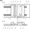
- ⁇ Coefficient of variation of linear velocity of cleaning liquid at inflow section CV [-]> 1 and 2 illustrate a method for measuring the linear velocity of the cleaning liquid at the inflow portion.
- Styrofoam which is a sphere with a diameter of 3 mm, is floated on the cleaning liquid, and the time taken for the central part of the expanded polystyrene to move 30 mm in the opposite direction to the direction of travel of the coagulated yarn bundle is measured on the surface of the inflowing cleaning liquid. Calculate the linear velocity at the inlet. However, when it flows from the nozzle, as shown in FIG. 2, the time for moving 30 mm further from the point of 30 mm in the traveling direction of the cleaning liquid is measured from the nozzle.
- Range from the end coagulated yarn bundle running in parallel to the end coagulated yarn bundle that is, 9 points at equal intervals including points A and B in the AB line segment shown in FIGS.
- Measurement was made to determine the linear velocity of the cleaning liquid.
- the ratio between the arithmetic mean and the standard deviation was defined as CV of the linear velocity of the cleaning liquid at the inflow part. This measurement is performed under conditions for producing an acrylic fiber bundle.
- the standard deviation was obtained by the following mathematical formula (1).
- x i (i takes a value of 1 to 9) represents a linear velocity
- ⁇ 1 is an arithmetic average of x 1 to x 9 .
- FIG. 3 illustrates a method for measuring the CV of the linear velocity of the cleaning liquid at the outflow portion.
- Styrofoam which is a sphere with a diameter of 3 mm, is floated on the cleaning liquid, and the time taken for the central part of the expanded polystyrene to move 30 mm parallel to the direction in which the coagulated yarn bundle travels on the liquid surface before the cleaning liquid flows out is measured.
- the ratio between the arithmetic average and the standard deviation is calculated as CV, and is defined as CV of the linear velocity of the cleaning liquid at the outflow part. This measurement is performed under conditions for producing an acrylic fiber bundle.
- the standard deviation is defined as in the above formula (1).
- a plurality of coagulated yarn bundles are supplied from the upstream inlet of the countercurrent cleaning bath below the surface of the cleaning bath by a rotating supply roller or guide. Then, it is carried out of the washing bath from the downstream outlet by the same means. This form is called a tray-type cleaning bath.
- the solidified yarn bundle carried out is supplied to the next washing bath.
- the coagulated yarn bundle unloaded from the cleaning bath in which the cleaning bath is located on the most downstream side is supplied to an oil supply device or the like. In cleaning, it is preferable to heat the cleaning solution, and in at least some of the cleaning baths, it is preferable to stretch the coagulated yarn bundle simultaneously with water cleaning.
- countercurrent cleaning baths having an inflow portion and an outflow portion for the cleaning liquid.
- a plurality of countercurrent washing baths it is preferable that they are arranged in series in the direction of a plurality of coagulated yarn bundles running in parallel.
- the number of countercurrent washing baths is preferably 5 to 40, more preferably 5 to 30, and still more preferably 10 to 25. If it is 5 baths or more, the solvent contained in the coagulated yarn bundle is sufficiently removed, and if it is 10 baths or more, the cleaning liquid can have a concentration gradient, so that the cleaning efficiency can be increased. It is preferable that it is 40 or less from a viewpoint of the expense concerning facilities.
- the linear coefficient of variation of the linear velocity of the cleaning liquid in the inflow portion of one countercurrent cleaning bath is not more than 0.30 in all the cleaning baths, and the linear velocity of the cleaning liquid in the outflow portion of one cleaning bath.
- the average coefficient of variation CV of all cleaning baths must be 0.30 or less.
- all countercurrent cleaning baths have a linear CV of the cleaning liquid at the inflow portion of 0.30 or less and a linear CV of the cleaning liquid at the outflow of 0.30 or less.
- At least one of the following means a) to c) is done by one means.
- smoothly changing means that there is no minimum point or maximum point between the center portion and each end portion.
- the following cleaning liquid flows in and out.
- the cleaning liquid is introduced from the downstream side using an overflow weir.
- ii) Subsequently, it flows into the countercurrent cleaning bath immediately upstream of the countercurrent cleaning bath through an aperture plate having a porosity of 10 to 60% downstream of the countercurrent cleaning bath.
- iii) Further, the cleaning liquid is allowed to flow into the countercurrent cleaning bath immediately upstream of the countercurrent cleaning bath from a nozzle on the downstream side of the countercurrent cleaning bath via a pump or the like.
- the material of the weir, nozzle, and aperture plate is not limited, and, for example, a material that is not corroded by the cleaning liquid and not deformed by heat, such as stainless steel, is preferable.
- the difference in height between the both ends with respect to the central portion of the weir is 0.0 to ⁇ 7.0 mm because variation in the flow rate of the cleaning liquid is suppressed.
- the difference in height is more preferably +1.0 to ⁇ 5.0 mm, further preferably 0.0 to ⁇ 3.0 mm, and the line at the upper end of the weir is smooth from the center to each end. Preferably it has changed.
- the height of the central portion or the end portion of the weir is a height of the upper end of the part from the horizontal plane when a certain horizontal plane is imagined. A positive difference in height means that the height of the end is higher than the height of the center.
- the shape of the hole is not limited. Further, it is preferable to use a nozzle having 0.5 N or more holes, and more preferably 0.7 to 3.0 N, and even more preferably 0.8 to 1.2 N, the unevenness of the linear velocity of the cleaning liquid is suppressed. effective.
- N is an integer of 3 or more, and is the number of coagulated yarn bundles that run in parallel.
- positioning of a hole Preferably, when the hole density of both ends is higher than the hole density of a center part, there exists an effect which suppresses the nonuniformity of the linear velocity of a washing
- the cleaning liquid at this time is preferably sprayed in parallel with the traveling coagulated yarn bundle, not directly from the vertical direction of the traveling coagulated yarn bundle.
- unevenness in the linear velocity of the flowing cleaning liquid may occur, and unevenness in cleaning of the coagulated yarn bundle may occur.
- a perforated plate or a net can be used for the aperture plate.
- the shape of the plate and the shape of the holes are not limited.
- the open area ratio below the liquid surface is preferably 10 to 60%. More preferably, it is 30 to 50% at both end portions of the plate, and the central portion is 10 to 40% or less. More preferably, both end portions of the plate are 40 to 50% and the central portion is 20 to 30% or less. By doing so, the linear velocity distribution is reduced.
- the plate with holes is a mesh
- a wire mesh can be used.
- the size of the net is preferably 24 mesh or more, more preferably 60 mesh or more, and further preferably 100 mesh or more. This reduces the linear velocity distribution of the cleaning liquid.
- the cleaning liquid to be used may be any liquid that cleans and removes the solvent contained in the acrylic fiber bundle, and it is preferable to use water from the viewpoint of solvent recovery and the cost of the cleaning liquid.
- At least one of the following d) and e) It is preferable to carry out by.
- d) Outflow due to overflow using an overflow weir with a difference in height between both ends relative to the center of the weir being 0.0 to ⁇ 7.0 mm. More preferably, the height smoothly changes from the central portion of the weir to both ends.
- smooth change means that there is no local minimum point or local maximum point from the center to each end.
- the cleaning liquid flows out from the cleaning bath downstream with respect to the traveling direction of the coagulated yarn bundle by using an overflow weir, and subsequently, the opening rate is 10 to one upstream with respect to the traveling direction of the coagulated yarn bundle.
- Each outflow method can be combined, such as outflow using a 60% plate.
- the aperture plate is preferably the same as the aperture plate described in the inflow portion of this specification. Even when the aperture ratio and the mesh size are such, the distribution of the linear velocity of the cleaning liquid becomes small.
- the number of washing baths is counted as 2 when the bathtub is divided into two in the yarn traveling direction by the overflow weir or the aperture plate. .
- the number is counted as three.
- the traveling coagulated yarn bundle needs to be below the liquid level of the cleaning liquid, but the coagulated yarn bundle can be made to travel above the liquid surface by using a conveyance roller, a guide, or the like between the cleaning baths.
- the coagulated yarn bundle preferably has a yarn bundle density index M defined by the following formula of 500 to 5000 dtex / mm, more preferably 1000 to 3000 dtex / mm.
- a yarn bundle density index M defined by the following formula of 500 to 5000 dtex / mm, more preferably 1000 to 3000 dtex / mm.
- all the solidified yarn bundles preferably have a yarn bundle width density index L defined by the following formula of 5 to 100%, more preferably 5 to 90%, and still more preferably 10 to 80%. In some cases, the effects of the present invention become significant. If it is 5% or more, fiber mixing between the coagulated yarn bundles is suppressed, and it is preferably 100% or less from the viewpoint of costs for facilities and the like.
- L [%] (Distance between coagulated yarn bundles [mm]) ⁇ 100 / (Coagulated yarn bundle width [mm]).
- the solvent residual amount derived from spinning in the yarn bundle is 1000 mass ppm or less, and further 400 mass ppm or less.
- the solvent residual amount derived from spinning in the yarn bundle is 1000 mass ppm or less, and further 400 mass ppm or less.
- the residual amount of solvent in the yarn yarn affects the generation of voids in the drying process or the adhesion between single fibers.
- an index representing the unevenness in washing between the yarn bundles there is a variation in the residual solvent amount.
- the variation coefficient CV of the solvent residual amount is preferably 0.25 or less, and more preferably less than 0.15.
- the cleaning liquid may be showered on the yarn bundle before or after the treatment process in the bath, or a pressurized gas is injected onto the yarn bundle. Good. Further, ultrasonic treatment may be performed on the yarn bundle, the roller, and the cleaning liquid.
- the cleaning baths are stretched simultaneously with cleaning by giving a speed difference between the roller rotation on the inlet side and the roller rotation on the outlet side. Stretching can be performed by setting stretching ratios of a plurality of cleaning baths for stretching for each cleaning bath in order to obtain a target stretching ratio. Stretching in a part of the first or second half bath and not stretching in the other baths can be performed while applying a tension to the extent that the yarn is tensioned.
- the yarn bundle is usually stretched about 2 to 6 times in a liquid at 50 to 98 ° C., and further an oil agent is applied. Thereafter, drying treatment with a hot roller or the like, secondary stretching by applying steam, and the like can be performed.
- the acrylic fiber of the acrylic fiber bundle obtained in this way is excellent in the processability of carbon fiber bundle production and the quality of the obtained carbon fiber bundle, particularly when used as a precursor of carbon fiber.
- the acrylic fiber bundle obtained by the above-described manufacturing method is flameproofed in an oxidizing atmosphere at 200 to 300 ° C.
- an oxidizing atmosphere at 200 to 300 ° C.
- the obtained flame-resistant fiber bundle is heated to 1000 ° C. or higher in an inert atmosphere such as nitrogen to produce a carbon fiber bundle.
- the obtained carbon fiber bundle can be widely used not only for sports and aerospace applications but also for general industrial applications such as automobiles, windmills, and pressure vessels as a reinforcing material for composite materials.
- the new cleaning liquid is allowed to flow into the countercurrent cleaning bath located on the most downstream side in the traveling direction of the coagulated yarn bundle.
- the cleaning liquid flows in from the downstream side, and the cleaning liquid flows out from the upstream side. If there is a countercurrent cleaning bath on the upstream side, the cleaning liquid flowing out from the countercurrent cleaning bath is allowed to flow into the countercurrent cleaning bath immediately upstream.
- ⁇ CV [-] of the linear velocity of the cleaning liquid at the inflow section> 1 and 2 illustrate a method for measuring the CV of the linear velocity of the cleaning liquid at the inflow portion of the countercurrent cleaning bath.
- Styrofoam which is a sphere with a diameter of 3 mm, is floated on the cleaning liquid, and the time taken for the central part of the expanded polystyrene to move 30 mm in the direction parallel to the coagulated yarn bundle on the surface of the inflowing cleaning liquid is measured.
- the time for moving further 30 mm from the point of 30 mm in the traveling direction of the cleaning liquid, that is, in the upstream direction was measured.
- x i (i takes a value of 1 to 9) represents a linear velocity
- ⁇ 1 is an arithmetic average of x 1 to x 9 .
- FIG. 3 illustrates a method for measuring the CV of the linear velocity of the cleaning liquid at the outflow portion.
- Styrofoam which is a sphere with a diameter of 3 mm, is floated on the cleaning liquid, and the time taken for the central part of the expanded polystyrene to move 30 mm in the direction opposite to and parallel to the direction of travel of the coagulated yarn bundle on the surface of the cleaning liquid that flows out The linear velocity in parts was calculated.
- ⁇ Solvent in yarn bundle The yarn bundle after passing through the treatment process in the bath was collected. It was boiled in 100 ° C. distilled water for 1.5 hours. The yarn bundle was dehydrated with a centrifugal separator and then dried with a dryer at 100 ° C. for 2.0 hours. Thereafter, the mass was measured to obtain a sample dry mass (g). In addition, the mixture of the boiled liquid and the liquid squeezed with a centrifuge was concentrated by evaporating water using a 100 ° C. water bath. The concentrated solution was analyzed by gas chromatography, and the mass (g) of dimethyl sulfoxide (hereinafter referred to as “DMSO”) was determined using a calibration curve prepared in advance, and the amount of solvent remaining in the yarn bundle was determined.
- DMSO dimethyl sulfoxide
- y n (n takes a value of 1 to N) represents the residual amount of solvent
- ⁇ 2 is an arithmetic average of y 1 to y N.
- N is the number of coagulated yarn bundles.
- the mass of the acrylic polymer in the coagulated yarn bundle is determined by sampling the polymer discharged for a certain period of time, extracting the solvent with hot water, and then drying it with a dryer at 100 ° C. for 2.0 hours. It was set as the mass of what remained.
- the mass of the cleaning liquid flowing into the cleaning bath located on the most downstream side at the same time was measured and determined by the ratio.
- Example 1 A DMSO solution consisting of 99.5 mol% of acrylonitrile and 0.5 mol% of itaconic acid and containing 20% by mass of an acrylic copolymer is spun into a coagulation bath consisting of DMSO and water as a spinning solution, and coagulated. A yarn bundle was obtained.
- the coagulated yarn bundle was run in a countercurrent washing bath in which a plurality were arranged in series, and washing in the bath was performed. Double wavy lines mean that illustration of a plurality of countercurrent washing baths is omitted.
- the number of countercurrent washing baths is ten.
- the height difference between both ends with respect to the central portion of the weir is ⁇ 3.0 mm, and the height from the upper end portion of the central portion to the upper end portion of each end portion is high.
- the cleaning liquid was allowed to flow over the overflow weir 5d, the length of which changed smoothly. From the countercurrent cleaning bath, the cleaning liquid flowed over the overflow weir of the same form as previously described. Furthermore, using a countercurrent cleaning bath having an inflow overflow weir and an outflow overflow weir of the same form, the cleaning liquid was introduced and the cleaning liquid was discharged. This inflow and outflow were performed in all countercurrent washing baths. In each countercurrent washing bath, the linear velocity CV of the inflow and outflow of the cleaning liquid was measured. Further, the residual solvent amount of the yarn bundle after the treatment in the bath was measured, and the residual solvent amount CV was calculated.
- the washed yarn bundle was stretched in a bath, and further an oil agent was applied in the bath.
- an oil agent an oil agent containing amino-modified silicone was used.
- the yarn bundle is dried until the moisture content of the yarn bundle becomes 1% by mass or less, and then stretched in pressurized steam, whereby an acrylic fiber bundle having 12,000 filaments is obtained.
- the amount of yarn bundle fluff after steam drawing was measured. The results shown in Table 1 and Table 2 were obtained. Thereafter, the obtained acrylic fiber bundle was flame-resistant while being conveyed in a flame-resistant furnace at 240 to 280 ° C. in air with a drive roll, and converted into a flame-resistant fiber bundle.
- carbonization is carried out while conveying in a carbonization furnace in an inert atmosphere at 1500 ° C. with a driving roll, and a carbon fiber bundle Got.
- Example 2 Manufacture and evaluation were performed in the same manner as in Example 1 except that the cleaning liquid mass ratio was set to 13, and an acrylic fiber bundle was obtained. Measurement and evaluation were performed in the same manner. The results are shown in Tables 1 and 2. Thereafter, a carbon fiber bundle was obtained from the obtained acrylic fiber bundle in the same manner as in Example 1.
- Example 3 Manufacture and evaluation were performed in the same manner as in Example 1 except that the number of countercurrent washing baths was 13, and an acrylic fiber bundle was obtained. The results are shown in Tables 1 and 2. Thereafter, a carbon fiber bundle was obtained from the obtained acrylic fiber bundle in the same manner as in Example 1.
- the countercurrent washing bath 1 d located on the most downstream side has a height of 0.0 mm at both ends with respect to the central portion of the weir, and from the upper end portion of the central portion to the upper end portion of each end portion.
- the cleaning liquid flowed over the overflow weir 5d which is a straight line. From the counter-current washing bath 1d, the washing liquid flowed over the overflow weir in the same form as the overflow weir 5d.
- the washing liquid that flowed out flowed over the overflow weir in the same form as the overflow weir 5d.
- Example 5 Manufacture was carried out in the same manner as in Example 4 except that the cleaning liquid mass ratio was set to 7, thereby obtaining an acrylic fiber bundle. Measurement and evaluation were performed in the same manner. The results are shown in Tables 1 and 2. Thereafter, a carbon fiber bundle was obtained from the obtained acrylic fiber bundle in the same manner as in Example 1.
- Example 6 Manufacture was carried out in the same manner as in Example 4 except that the cleaning liquid mass ratio was changed to 4, and an acrylic fiber bundle was obtained. Measurement and evaluation were performed in the same manner. The results are shown in Tables 1 and 2. Thereafter, a carbon fiber bundle was obtained from the obtained acrylic fiber bundle in the same manner as in Example 1.
- Example 7 Manufacture was carried out in the same manner as in Example 4 except that the treatment in the bath was performed in a countercurrent washing bath in which seven were arranged in series to obtain an acrylic fiber bundle. Measurement and evaluation were performed in the same manner. The results are shown in Tables 1 and 2. Thereafter, a carbon fiber bundle was obtained from the obtained acrylic fiber bundle in the same manner as in Example 1.
- Example 8 Manufacture was carried out in the same manner as in Example 4 except that the treatment in the bath was performed using a countercurrent washing bath in which four were arranged in series to obtain an acrylic fiber bundle. Measurement and evaluation were performed in the same manner. The results are shown in Tables 1 and 2. Thereafter, a carbon fiber bundle was obtained from the obtained acrylic fiber bundle in the same manner as in Example 1.
- Example 9 An overflow weir was manufactured in the same manner as in Example 4 except that the difference in height between both ends with respect to the central portion of the weir was ⁇ 7.0 mm, and an acrylic fiber bundle was obtained. Measurement and evaluation were performed in the same manner. The results are shown in Tables 1 and 2. Thereafter, a carbon fiber bundle was obtained from the obtained acrylic fiber bundle in the same manner as in Example 1.
- Example 10 An acrylic fiber bundle was obtained in the same manner as in Example 4 except that the height of both ends of the overflow weir with respect to the central portion of the weir was +5.0 mm. Measurement and evaluation were performed in the same manner. The results are shown in Tables 1 and 2. Thereafter, a carbon fiber bundle was obtained from the obtained acrylic fiber bundle in the same manner as in Example 1.
- Example 11 As shown in FIG. 5, the coagulated yarn bundle was run in a countercurrent washing bath in which a plurality were arranged in series, and washing in the bath was performed. Double wavy lines mean that illustration of a plurality of countercurrent washing baths is omitted.
- the countercurrent cleaning bath 1d at the most downstream side is supplied with cleaning liquid using an inflow nozzle having 40 holes, and the height difference between both ends with respect to the central portion is ⁇ 5.0 mm.
- the cleaning liquid flowed over the overflow weir where the height from the upper end to the upper end of each end changed smoothly.
- the cleaning liquid was flowed into the countercurrent washing bath one upstream using an inflow nozzle having 40 holes having the same form as that used in the countercurrent washing bath located at the most downstream side. From the countercurrent washing bath, the washing liquid flowed over the overflow weir in the same form as that used for the countercurrent washing bath located at the most downstream side.
- Example 1 The conditions other than the inflow and outflow of the cleaning liquid were produced in the same manner as in Example 1 to obtain an acrylic fiber bundle. Measurement and evaluation were performed in the same manner. The results are shown in Tables 1 and 2. Thereafter, a carbon fiber bundle was obtained from the obtained acrylic fiber bundle in the same manner as in Example 1.
- Example 12> As shown in FIG. 5, the cleaning liquid flows into the counter-current cleaning bath 1d located on the most downstream side using an inflow nozzle having 150 holes, and then the difference in height between both ends with respect to the central portion is 0.0 mm. Then, the overflow from the upper end portion of the central portion to the upper end portion of the weir to each end portion flowed out beyond the overflow weir.
- the washing liquid that flowed out was flowed into the countercurrent washing bath one upstream using an inflow nozzle having 150 holes similar to that used in the countercurrent washing bath 1d located on the most downstream side. In each countercurrent washing bath, the same inflow and outflow of the cleaning solution were performed.
- Example 2 Production was carried out in the same manner as in Example 1 except for the outflow and inflow in the countercurrent washing bath to obtain an acrylic fiber bundle. Measurement and evaluation were performed in the same manner. The results are shown in Tables 1 and 2. Thereafter, a carbon fiber bundle was obtained from the obtained acrylic fiber bundle in the same manner as in Example 1.
- Example 13> Instead of the overflow weir, inflow and outflow aperture plates were used.
- the aperture ratio of the aperture plate was 31%.
- Production was carried out in the same manner as in Example 1 except for the outflow and inflow in the countercurrent washing bath to obtain an acrylic fiber bundle. Measurement and evaluation were performed in the same manner. The results are shown in Tables 1 and 2. Thereafter, a carbon fiber bundle was obtained from the obtained acrylic fiber bundle in the same manner as in Example 1.
- Example 14 In each cleaning bath, the cleaning liquid is removed by an overflow weir with a height difference of 0.0 mm at both ends relative to the central portion of the weir and a straight line from the upper end of the central portion to the upper end of both ends. Then, the cleaning liquid was discharged from each countercurrent cleaning bath through a plate having a porosity of 31%. Conditions other than the countercurrent washing bath were produced in the same manner as in Example 1 to obtain an acrylic fiber bundle. Measurement and evaluation were performed in the same manner. The results are shown in Tables 1 and 2. Thereafter, a carbon fiber bundle was obtained from the obtained acrylic fiber bundle in the same manner as in Example 1.
- Example 15 In each counter-current cleaning bath, the cleaning liquid was introduced using an inflow nozzle having 20 holes, and the cleaning liquid was discharged through a plate having an aperture ratio of 31%. Production was performed in the same manner as in Example 1 except for the outflow and inflow in the countercurrent washing bath to obtain an acrylic fiber bundle. Measurement and evaluation were performed in the same manner. The results are shown in Tables 1 and 2. Thereafter, a carbon fiber bundle was obtained from the obtained acrylic fiber bundle in the same manner as in Example 1.
- Example 16> In each counter-current cleaning bath, the cleaning liquid flows in through a plate with a 10% porosity, and the height difference between both ends with respect to the central portion of the weir is 0.0 mm, and the upper end of each end from the upper end of the central portion. The cleaning liquid flowed over the overflow weir that was straight up to the part. Production was performed in the same manner as in Example 1 except for the inflow and outflow in the countercurrent washing bath, and an acrylic fiber bundle was obtained. The results are shown in Tables 1 and 2. Then, it carried out similarly to Example 1 from the obtained acrylic fiber bundle, and obtained the carbon fiber bundle.
- Example 17 In each countercurrent cleaning bath, the cleaning liquid was introduced through a plate having a porosity of 60%, and the cleaning liquid was discharged through a plate having a porosity of 60%. Manufacture was carried out in the same manner as in Example 1 except for the conditions for outflow and inflow to obtain an acrylic fiber bundle. Measurement and evaluation were performed in the same manner. The results are shown in Tables 1 and 2. Thereafter, a carbon fiber bundle was obtained from the obtained acrylic fiber bundle in the same manner as in Example 1.
- Example 3 Production was carried out in the same manner as in Example 1 except that the cleaning liquid was introduced through a plate having a porosity of 65% in each counter-current cleaning bath and the cleaning liquid was discharged through a plate having a porosity of 65% to obtain an acrylic fiber bundle. . Measurement and evaluation were performed in the same manner. The results are shown in Tables 1 and 2.
Landscapes
- Engineering & Computer Science (AREA)
- Textile Engineering (AREA)
- Chemical & Material Sciences (AREA)
- Chemical Kinetics & Catalysis (AREA)
- General Chemical & Material Sciences (AREA)
- Health & Medical Sciences (AREA)
- Toxicology (AREA)
- Mechanical Engineering (AREA)
- Organic Chemistry (AREA)
- Inorganic Chemistry (AREA)
- Spinning Methods And Devices For Manufacturing Artificial Fibers (AREA)
- Artificial Filaments (AREA)
- Inorganic Fibers (AREA)
Abstract
Description
(1)アクリル系重合体溶液を紡糸して凝固糸条束とした後、凝固糸条束に対して少なくとも浴中処理工程および油剤付与工程を行うアクリル系繊維束の製造方法であって、
前記浴中処理工程は、浴中洗浄工程を含み、
前記浴中洗浄工程は、前記凝固糸条束複数本が、洗浄液の流入部および流出部を備えた1つ以上の洗浄浴中において、並列に走行し、洗浄される工程であって、
少なくとも1つの洗浄浴は、洗浄液が凝固糸条束の走行方向の下流側の位置にある流入部から流入し、凝固糸条束の走行方向の上流側の位置にある流出部から流出する向流洗浄浴であって、
前記向流洗浄浴の流入部における洗浄液の線速度の変動係数CVの平均が0.30以下、前記向流洗浄浴の流出部における洗浄液の線速度の変動係数CVの平均が0.30以下である、
アクリル系繊維束の製造方法。
アクリル系繊維束の好ましい製造方法として、さらに以下の好ましい態様がある。
(2)洗浄液の流入を、下記a)~c)の手段のうち少なくとも1つの手段によって行う前記アクリル系繊維束の製造方法。
a)堰の中央部に対する両端部の高さの差が0.0~±7.0mmであるオーバーフロー堰を用いたオーバーフローによる流入。
b)0.5N個以上の孔のノズルからの流入(Nは3以上の整数であって、並列に走行させる凝固糸条束の本数である。)。
c)複数の孔を有する板からの流入であって、板の面積に対する複数の孔の面積の和の比率(開孔率)が10~60%である。
(3)洗浄液の流出を、下記d)、e)の手段のうち少なくとも1つの手段によって行う前記いずれかのアクリル系繊維束の製造方法。
d)堰の中央部に対する両端部の高さの差が0.0~±7.0mmであるオーバーフロー堰を用いたオーバーフローによる流出。
e)複数の孔を有する板からの流出であって、板の面積に対する複数の孔の面積の和の比率(開孔率)が10~60%である。
(4)向流洗浄浴が、並列に走行する複数本の凝固糸条束に沿って直列に複数配置されている前記いずれかのアクリル系繊維束の製造方法。
(5)次式により定義される糸条束密度指数Mが500~5000dtex/mmの凝固糸条束を、3本以上並列に走行させ、次式により定義される凝固糸条束の糸条束幅密度指数Lが5~100%で浴中処理する前記のいずれか記載のアクリル系繊維束の製造方法。
L[%]=(凝固糸条束間距離[mm])×100/(凝固糸条束幅[mm])
また炭素繊維束の製造方法として、本発明は以下の構成を開示する。
(6)前記いずれかのアクリル系繊維束の製造方法でアクリル系繊維束を製造した後、酸化性雰囲気中での耐炎化処理、次いで不活性雰囲気中で炭化処理を行う炭素繊維束の製造方法。
図1および図2は流入部での洗浄液の線速度の測定方法を図示したものである。洗浄液に直径3mmの球体である発泡スチロールを浮かせ、流入される洗浄液の液面上を、発泡スチロールの中心部が、凝固糸条束が走行する方向と平行にかつ反対方向に30mm移動する時間を測定し流入部での線速度を算出する。ただし、ノズルから流入する場合は、図2のようにノズルから洗浄液の進行方向へ30mmの地点から、さらに30mm移動する時間を測定する。並列に走行する端の凝固糸条束から端の凝固糸条束までの範囲、すなわち図1および図2に示したA-B線分の、A点、B点を含めて等間隔で9点測定し、洗浄液の線速度を求めた。その算術平均と標準偏差の割合を流入部での洗浄液の線速度のCVとした。尚、本測定はアクリル系繊維束を製造する条件の下で行う。ここで標準偏差は、下記の数式(1)で求めた。

図3は、流出部での洗浄液の線速度のCVの測定方法を図示したものである。洗浄液に直径3mmの球体である発泡スチロールを浮かせ、洗浄液が流出される前の液面上を、凝固糸条束が走行する方向と平行に発泡スチロールの中心部が30mm移動する時間を測定し、流出部での線速度を算出する。並列して走行する端の凝固糸条束から端の凝固糸条束までの範囲、すなわち図3中のA-B線分の、A点、B点を含めて等間隔で9点測定し、その算術平均と標準偏差の割合をCVとして算出し流出部での洗浄液の線速度のCVとする。尚、本測定はアクリル系繊維束を製造する条件の下で行う。また、ここで標準偏差は上記数式(1)のように定義する。
a)堰の中央部に対する両端部の高さの差が0.0~±7.0mmであるオーバーフロー堰を用いたオーバーフローによる流入。さらに好ましくは、堰の中央部から両端部へ高さが平滑に変化している。ここで、平滑に変化するとは、中央部からそれぞれの端部までの間で極小点もしくは極大点がないことを示す。
b)0.5N個以上の孔を有するノズル(Nは3以上の整数であって、並列に走行させる凝固糸条束の本数である。)による流入。
c)開孔板からの流入であって、板の面積に対する複数の孔の面積の和の比率(開孔率)が10~60%である。
i)最も下流にある向流洗浄浴において、下流側からオーバーフロー堰を用いて洗浄液を流入する。
ii)続いて、その向流洗浄浴のすぐ上流にある向流洗浄浴へ、向流洗浄浴の下流側にある開孔率10~60%の開孔板を通じて流入する。
iii)さらに、その向流洗浄浴のすぐ上流にある向流洗浄浴へ、ポンプ等を介してその向流洗浄浴の下流側にあるノズルから洗浄液を流入する。
d)堰の中央部に対する両端部の高さの差が0.0~±7.0mmであるオーバーフロー堰を用いたオーバーフローによる流出。さらに好ましくは、堰の中央部から両端部へ高さが平滑に変化している。ここでも、平滑に変化するとは、中央部からそれぞれの端部までの間で極小点もしくは極大点がないことを示す。
e)複数の孔を有する板からの流出であって、板の面積に対する複数の孔の面積の和の比率(開孔率)が10~60%である。
<洗浄液の流れ>
水を洗浄液として用いた。各実施例、比較例では、新しい洗浄液は、凝固糸条束の走行方向の最下流にある向流洗浄浴に流入させている。それぞれの向流洗浄浴においては、その下流のところから洗浄液を流入し、その上流のところから洗浄液を流出させている。向流洗浄浴から流出した洗浄液は、上流側に向流洗浄浴がある場合は、そのすぐ上流側にある向流洗浄浴に流入させている。
図1および図2は向流洗浄浴の流入部での洗浄液の線速度のCVの測定方法を図示したものである。洗浄液に直径3mmの球体である発泡スチロールを浮かせ、流入される洗浄液の面上を、発泡スチロールの中心部が、凝固糸条束と平行な方向に30mm移動する時間を測定し、流入部での線速度を算出した。ただし、ノズルから流入する場合は、図2のようにノズルから洗浄液の進行方向へ、すなわち上流方向へ、30mmの地点を始点として、さらに30mm移動する時間を測定した。並列に走行する凝固糸条束の最も端から反対の最も端の凝固糸条束までの範囲、すなわち図1および図2中のA-B線分の間で、A点、B点を含んで、等間隔の9点を測定し、その算術平均と標準偏差の割合を求め、流入部での洗浄液の線速度のCVとした。尚、本測定はアクリル系繊維束を製造する条件の下で行った。また、標準偏差は、下記の数式(1)で求めた。

図3は流出部での洗浄液の線速度のCVの測定方法を図示したものである。洗浄液に直径3mmの球体である発泡スチロールを浮かせ、流出される洗浄液の面上を、凝固糸条束が走行する方向と逆方向に、かつ平行に発泡スチロールの中心部が30mm移動する時間を測定し流出部での線速度を算出した。並列して走行する凝固糸条束のうち、最も端から反対の最も端の凝固糸条束までの範囲、すなわち図3中のA-B線分の間で、A点、B点を含んで等間隔の9点を測定し、その算術平均と標準偏差の割合を求め、流出部での洗浄液の線速度のCVとした。尚、本測定はアクリル系繊維束を製造する条件の下で行った。また標準偏差は上記数式(1)で求めた。
質量は、JIS L0105(2006)に基づき20±2℃、相対湿度65%±4%の条件で測定した。
浴中処理工程通過後の糸条束を採取した。それを100℃の蒸留水中で1.5時間煮沸した。その糸条束を遠心分離機で脱水した後、100℃の乾燥機で2.0時間乾燥し、その後質量を測り、試料乾燥質量(g)とした。また、前記煮沸した液および遠心分離機で絞った液の混合液を100℃のウォーターバスを用いて水分を蒸発し濃縮した。その濃縮液をガスクロマトグラフィーによって分析し、予め作成した検量線を用いてジメチルスルフォキサイド(以下「DMSO」と言う)の質量(g)を求め、糸条束に残存する溶媒の量とした。ここで、アセト酢酸メチルを内部標準として用いた。溶媒残存量[糸条束中のDMSO残存量]は、計算式、糸条束中のDMSO残存量(ppm)=糸条束中のDMSO質量(g)×1000000/試料乾燥質量(g)により算出した。
並列に走行する全ての凝固糸条束の溶媒残存量を測定し、その算術平均と標準偏差の割合を求めて、溶媒残存量のCVとした。ここで標準偏差は下記の数式(2)で求めた。

単位時間あたりに向流洗浄浴中を走行する凝固糸条束中のアクリル系重合体の質量[g/分]に対する流入部から流入される洗浄液の単位時間あたりの質量[g/分]の比である。ここで、凝固糸条束中のアクリル系重合体の質量は、一定時間に吐出される重合体をサンプリングし、温水により溶媒等を抽出した後、100℃の乾燥機で2.0時間乾燥して残ったものの質量とした。一方最下流に位置する洗浄浴に、同じ時間に流入される洗浄液の質量を測定し、その比によって求めた。
洗浄浴の走行糸条束に対して下流のローラ出側において、並列して走行する糸条束間で走行距離100mの間に繊維同士が交差する頻度を数えた。
スチーム延伸後、走行する糸条束を目視により観察し、1つの糸条束1000mあたりの毛羽の発生個数を数えた。
アクリロニトリル99.5モル%、イタコン酸0.5モル%からなり、アクリル系共重合体を20質量%含むDMSO溶液を紡糸原液として、口金からDMSOと水からなる凝固浴中に紡出して、凝固糸条束を得た。
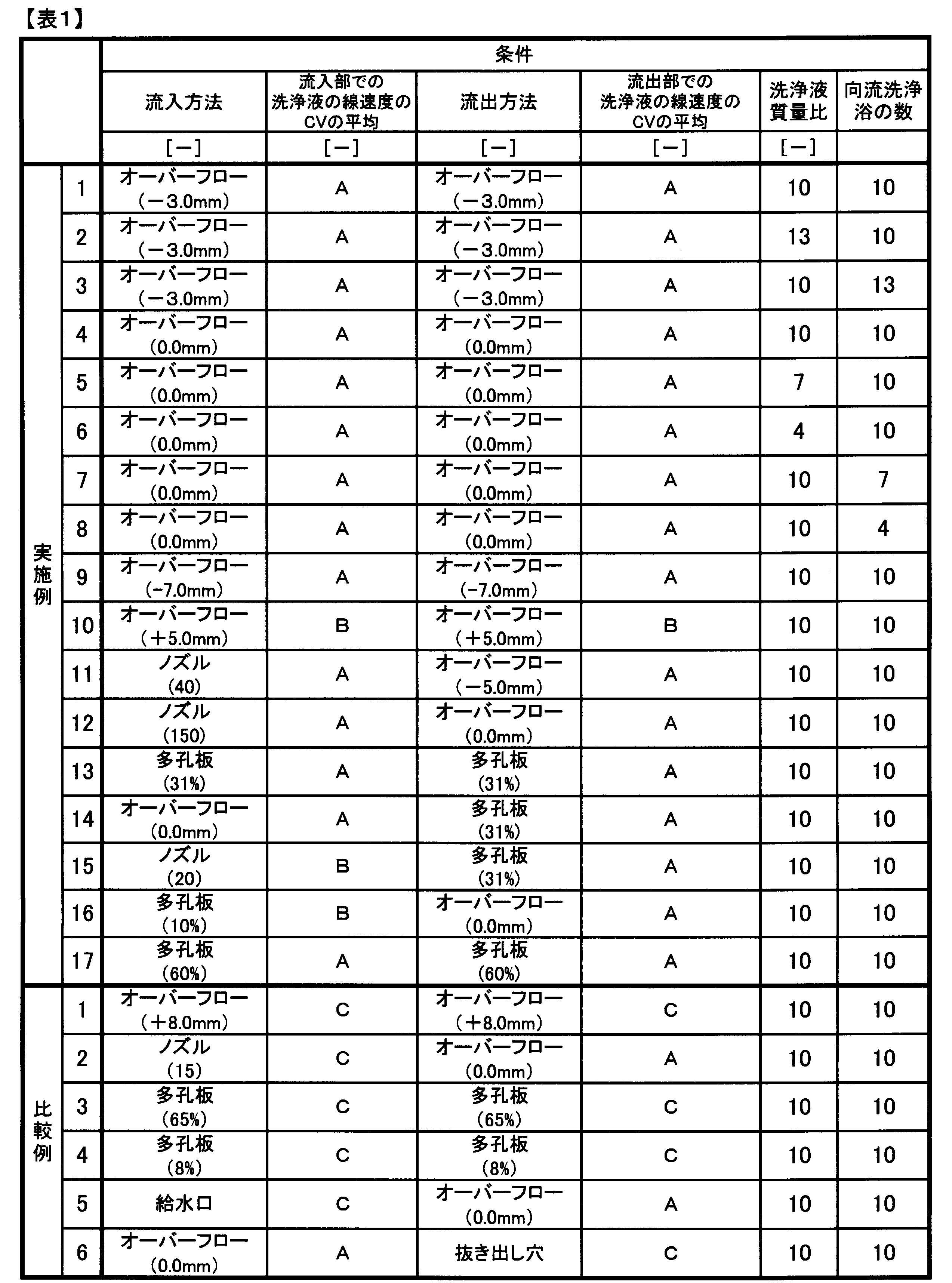
オーバーフローの場合:堰の中央部に対する両端部の高さの差
ノズルの場合:孔の数
多孔板の場合:開孔率。

A:0.25未満、B:0.25以上0.30以下、C:0.30より大きい
なお、表1中のCVの範囲(A、BまたはC)は、1つの向流洗浄浴の流入部における洗浄液の線速度のCVの全ての向流洗浄浴での平均が該範囲(A、BもしくはC)にあることを示す。
A:0.25未満、B:0.25以上0.30以下、C:0.30より大きい
なお、表1中のCVの範囲(A、BまたはC)は、1つの向流洗浄浴の流出部における洗浄液の線速度のCVの全ての向流洗浄浴での平均が該範囲(A、BもしくはC)にあることを示す。
A:0.15未満、B:0.15以上0.25以下、C:0.25より大きい。
A:10.0未満、B:10.0以上25.0未満、C:25.0以上。
A:0.0以上8.0未満、B:8.0以上16.0未満、C:16.0以上。
溶媒残存量のCV、混繊発生頻度、スチーム延伸後の糸条束毛羽発生量の各結果について、1項目でもCがある場合はC、Cはないが1項目でもBがある場合はB、全てがAの場合はAとした。
洗浄液質量比を13とした以外は実施例1と同様に製造、評価を行い、アクリル系繊維束を得た。また測定、評価も同様に行った。結果を表1および表2に示す。その後、得られたアクリル系繊維束から実施例1と同様の方法で炭素繊維束を得た。
向流洗浄浴の数を13とした以外は実施例1と同様に製造、評価を行い、アクリル系繊維束を得た。結果を表1および表2に示す。その後、得られたアクリル系繊維束から実施例1と同様の方法で炭素繊維束を得た。
<実施例4>
図4のように、最下流にある向流洗浄浴1dに、堰の中央部に対する両端部の高さが0.0mmであって、中央部の上端部からそれぞれの端部の上端部までが直線であるオーバーフロー堰5dを超えて洗浄液を流入した。向流洗浄浴1dから、オーバーフロー堰5dと同じ形態のオーバーフロー堰を超えて洗浄液を流出した。流出した洗浄液は、オーバーフロー堰5dと同じ形態のオーバーフロー堰を超えて流入した。このような洗浄液の流入、流出を各向流洗浄浴で行った。そして、最上流にある向流洗浄浴1tでは、最上流にあり、オーバーフロー堰5dと同じ形態のオーバーフロー堰5tにより流出した。それ以外の工程は、実施例1と同様に製造を行い、アクリル系繊維束を得た。また測定、評価も同様に行った。結果を表1および表2に示す。その後、得られたアクリル系繊維束から実施例1と同様の方法で炭素繊維束を得た。
洗浄液質量比7とした以外は、実施例4と同様に製造を行い、アクリル系繊維束を得た。また測定、評価も同様に行った。結果を表1および表2に示す。その後、得られたアクリル系繊維束から実施例1と同様の方法で炭素繊維束を得た。
洗浄液質量比4とした以外は実施例4と同様に製造を行い、アクリル系繊維束を得た。また測定、評価も同様に行った。結果を表1および表2に示す。その後、得られたアクリル系繊維束から実施例1と同様の方法で炭素繊維束を得た。
7つが直列で配置された向流洗浄浴で浴中処理を行った以外は、実施例4と同様に製造を行い、アクリル系繊維束を得た。また測定、評価も同様に行った。結果を表1および表2に示す。その後、得られたアクリル系繊維束から実施例1と同様の方法で炭素繊維束を得た。
4つが直列で配置された向流洗浄浴で浴中処理を行った以外は、実施例4と同様に製造を行い、アクリル系繊維束を得た。また測定、評価も同様に行った。結果を表1および表2に示す。その後、得られたアクリル系繊維束から実施例1と同様の方法で炭素繊維束を得た。
オーバーフロー堰を、堰の中央部に対する両端部の高さの差を-7.0mmにした以外は、実施例4と同様に製造を行い、アクリル系繊維束を得た。また測定、評価も同様に行った。結果を表1および表2に示す。その後、得られたアクリル系繊維束から実施例1と同様の方法で炭素繊維束を得た。
オーバーフロー堰を堰の中央部に対する両端部の高さを+5.0mmにした以外は、実施例4と同様に製造を行い、アクリル系繊維束を得た。また測定、評価も同様に行った。結果を表1および表2に示す。その後、得られたアクリル系繊維束から、実施例1と同様の方法で炭素繊維束を得た。
図5に示すように、複数が直列に配列している向流洗浄浴の中に凝固糸条束を走行させ、浴中洗浄を行った。なお二重の波線は複数の向流洗浄浴の図示を省略していることを意味する。
図5に示すように、最下流にある向流洗浄浴1dに、150個の孔を有する流入ノズルを用いて洗浄液を流入し、その後、中央部に対する両端部の高さの差が0.0mmであって、中央部の上端部からそれぞれの端部への堰の上端部までが直線であるオーバーフロー堰を超えて流出した。流出した洗浄液を、一つ上流の向流洗浄浴へ、ポンプにより最下流にある向流洗浄浴1dに用いたものと同様の150個の孔を有する流入ノズルを用いて流入した。各向流洗浄浴でも同様の洗浄液の流入、流出を行った。向流洗浄浴での流出、流入以外の条件は実施例1と同様に製造を行い、アクリル系繊維束を得た。また測定、評価も同様に行った。結果を表1および表2に示す。その後、得られたアクリル系繊維束から実施例1と同様の方法で炭素繊維束を得た。
オーバーフロー堰に代えて、流入用および流出用の開孔板を使用した。開孔板の開孔率は31%とした。向流洗浄浴での流出、流入以外の条件は実施例1と同様に製造を行い、アクリル系繊維束を得た。また測定、評価も同様に行った。結果を表1および表2に示す。その後、得られたアクリル系繊維束から実施例1と同様の方法で炭素繊維束を得た。
<実施例14>
各洗浄浴において、洗浄液を堰の中央部に対して両端部の高さの差が0.0mmであって中央部の上端部から両端部の上端部までが直線であるオーバーフロー堰により、洗浄液を流入させ、そして各向流洗浄浴から開孔率31%の板により洗浄液を流出した。向流洗浄浴以外の条件は、実施例1と同様に製造を行い、アクリル系繊維束を得た。また測定、評価も同様に行った。結果を表1および表2に示す。その後、得られたアクリル系繊維束から実施例1と同様の方法で炭素繊維束を得た。
<実施例15>
各向流洗浄浴において、20個の孔を有する流入ノズルを用いて洗浄液を流入し、開孔率31%の板を通じて洗浄液を流出した。向流洗浄浴での流出、流入以外での条件は実施例1と同様に製造を行い、アクリル系繊維束を得た。また測定、評価も同様に行った。結果を表1および表2に示す。その後、得られたアクリル系繊維束から実施例1と同様の方法で炭素繊維束を得た。
<実施例16>
各向流洗浄浴において、開孔率10%の板を通じて洗浄液を流入し、堰の中央部に対する両端部の高さの差が0.0mmで、中央部の上端部からそれぞれの端部の上端部までが直線であるオーバーフロー堰を超えて洗浄液を流出した。向流洗浄浴での流入、流出以外での条件は実施例1と同様に製造を行い、アクリル系繊維束を得た。結果を表1および表2に示す。その後、得られたアクリル系繊維束から実施例1と同様に行い炭素繊維束を得た。
<実施例17>
各向流洗浄浴で、開孔率60%の板を通じて洗浄液を流入し、開孔率60%の板を通じて洗浄液を流出した。流出、流入での条件以外は実施例1と同様に製造を行い、アクリル系繊維束を得た。また測定、評価も同様に行った。結果を表1および表2に示す。その後、得られたアクリル系繊維束から実施例1と同様の方法で炭素繊維束を得た。
図4に示すように、それぞれの向流洗浄浴に、洗浄液を堰の中央部に対する両端部の高さの差が+8.0mmであって、中央部の上端部からそれぞれの端部の上端部への高さが平滑に変化するオーバーフロー堰を超えて洗浄液を流入した。また洗浄液を流入したオーバーフロー堰と同様の形態のオーバーフロー堰を超えて洗浄液を流出した。流出、流入での条件以外は、実施例1と同様に製造を行い、アクリル系繊維束を得た。また測定、評価も同様に行った。結果を表1および表2に示す。
それぞれの向流洗浄浴では、15個の孔を有する流入ノズルを用いて洗浄液を流入し、堰の中央部に対する両端部の高さが0.0mmであって、中央部の上端部からそれぞれの端部の上端部までが直線であるオーバーフロー堰を超えて洗浄液を流出した。流出、流入以外は実施例1と同様に、製造を行い、アクリル繊維束を得た。また測定、評価も同様に行った。結果を表1および表2に示す。
それぞれの向流洗浄浴で開孔率65%の板を通じて洗浄液を流入し、開孔率65%の板を通じて洗浄液を流出した以外は実施例1と同様に製造を行い、アクリル繊維束を得た。また測定、評価も同様に行った。結果を表1および表2に示す。
それぞれの向流洗浄浴で開孔率8%の板を通じて洗浄液を流入し、開孔率8%の板を通じて洗浄液を流出した。流入、流出の条件以外は実施例1と同様に製造を行い、アクリル系繊維束を得た。また測定、評価も同様に行った。結果を表1および表2に示す。
それぞれの向流洗浄浴の最下流部に、液面の上部から直径30mmの円筒状の給水口を用いて洗浄液を流入した。各向流洗浄浴の最上流部に、堰の中央部に対する両端部の高さの差が0.0mmであって、中央部の上端部から両端部の上端部までが直線であるオーバーフロー堰を超えて、洗浄液を流出した。流入、流出の条件以外は実施例1と同様に行い、アクリル系繊維束を得た。また測定、評価も同様に行った。結果を表1および表2に示す。
それぞれの向流洗浄浴で、堰の中央部に対する両端部の高さの差が0.0mmであって中央部から両端部への上端部が直線であるオーバーフロー堰を超えて洗浄液を流入した。各向流洗浄浴では浴の最上流部の底に開けた抜き出し穴により洗浄液を流出した。それ以外は、実施例1と同様に製造を行い、アクリル繊維束を得た。また測定、評価も同様に行った。結果を表1および表2に示す。
1d:最下流にある向流洗浄浴
1t:最上流にある向流洗浄浴
2:洗浄液
3:糸条束
4:ロール
5:オーバーフロー堰
5d:最下流にあるオーバーフロー堰
5t:最上流にあるオーバーフロー堰
6:ノズル
7:ポンプ
X:糸条束走行方向
Y:洗浄液の流れる方向
Claims (6)
- アクリル系重合体溶液を紡糸して凝固糸条束とした後、凝固糸条束に対して少なくとも浴中処理工程および油剤付与工程を行うアクリル系繊維束の製造方法であって、
前記浴中処理工程は、浴中洗浄工程を含み、
前記浴中洗浄工程は、前記凝固糸条束複数本が、洗浄液の流入部および流出部を備えた1つ以上の洗浄浴中において、並列に走行し、洗浄される工程であって、
少なくとも1つの洗浄浴は、洗浄液が凝固糸条束の走行方向の下流側の位置にある流入部から流入し、凝固糸条束の走行方向の上流側の位置にある流出部から流出する向流洗浄浴であって、
前記向流洗浄浴の流入部における洗浄液の線速度の変動係数CVの平均が0.30以下、前記向流洗浄浴の流出部における洗浄液の線速度の変動係数CVの平均が0.30以下である、
アクリル系繊維束の製造方法。 - 洗浄液の流入を、下記a)~c)の手段のうち少なくとも1つの手段によって行う請求項1記載のアクリル系繊維束の製造方法。
a)堰の中央部に対する両端部の高さの差が0.0~±7.0mmであるオーバーフロー堰を用いたオーバーフローによる流入。
b)0.5N個以上の孔のノズルからの流入(Nは3以上の整数であって、並列に走行させる凝固糸条束の本数である。)。
c)複数の孔を有する板からの流入であって、板の面積に対する複数の孔の面積の和の比率(開孔率)が10~60%である。 - 洗浄液の流出を、下記d)、e)の手段のうち少なくとも1つの手段によって行う請求項1または2記載のアクリル系繊維束の製造方法。
d)堰の中央部に対する両端部の高さの差が0.0~±7.0mmであるオーバーフロー堰を用いたオーバーフローによる流出。
e)複数の孔を有する板からの流出であって、板の面積に対する複数の孔の面積の和の比率(開孔率)が10~60%である。 - 向流洗浄浴が、並列に走行する複数本の凝固糸条束に沿って直列に複数配置されている請求項1~3のいずれか記載のアクリル系繊維束の製造方法。
- 次式により定義される糸条束密度指数Mが500~5000dtex/mmの凝固糸条束を、3本以上並列に走行させ、次式により定義される凝固糸条束の糸条束幅密度指数Lが5~100%で浴中処理する請求項1~4のいずれか記載のアクリル系繊維束の製造方法。
M[dtex/mm]=(凝固糸条束1本あたりの繊度[dtex])/(凝固糸条束幅[mm])
L[%]=(凝固糸条束間距離[mm])×100/(凝固糸条束幅[mm]) - 請求項1~5のいずれか記載のアクリル系繊維束の製造方法でアクリル系繊維束を製造した後、酸化性雰囲気中での耐炎化処理、次いで不活性雰囲気中で炭化処理を行う炭素繊維束の製造方法。
Priority Applications (6)
| Application Number | Priority Date | Filing Date | Title |
|---|---|---|---|
| EP18747950.6A EP3578698B1 (en) | 2017-02-01 | 2018-01-30 | Method for producing acrylic fiber bundle and method for producing carbon fiber bundle |
| CN201880009484.2A CN110214206B (zh) | 2017-02-01 | 2018-01-30 | 丙烯酸系纤维束的制造方法和碳纤维束的制造方法 |
| US16/480,884 US10883195B2 (en) | 2017-02-01 | 2018-01-30 | Method of producing acrylic fiber bundle and method of producing carbon fiber bundle |
| KR1020197021289A KR102405429B1 (ko) | 2017-02-01 | 2018-01-30 | 아크릴계 섬유 다발의 제조 방법 및 탄소섬유 다발의 제조 방법 |
| JP2018506619A JP6388090B1 (ja) | 2017-02-01 | 2018-01-30 | アクリル系繊維束の製造方法および炭素繊維束の製造方法 |
| MX2019008750A MX2019008750A (es) | 2017-02-01 | 2018-01-30 | Metodo para producir haces de fibras acrilicas y metodo para producir haces de fibras de carbono. |
Applications Claiming Priority (2)
| Application Number | Priority Date | Filing Date | Title |
|---|---|---|---|
| JP2017-016467 | 2017-02-01 | ||
| JP2017016467 | 2017-02-01 |
Publications (1)
| Publication Number | Publication Date |
|---|---|
| WO2018143210A1 true WO2018143210A1 (ja) | 2018-08-09 |
Family
ID=63039601
Family Applications (1)
| Application Number | Title | Priority Date | Filing Date |
|---|---|---|---|
| PCT/JP2018/003008 Ceased WO2018143210A1 (ja) | 2017-02-01 | 2018-01-30 | アクリル系繊維束の製造方法および炭素繊維束の製造方法 |
Country Status (8)
| Country | Link |
|---|---|
| US (1) | US10883195B2 (ja) |
| EP (1) | EP3578698B1 (ja) |
| JP (1) | JP6388090B1 (ja) |
| KR (1) | KR102405429B1 (ja) |
| CN (1) | CN110214206B (ja) |
| MX (1) | MX2019008750A (ja) |
| TW (1) | TW201835398A (ja) |
| WO (1) | WO2018143210A1 (ja) |
Cited By (1)
| Publication number | Priority date | Publication date | Assignee | Title |
|---|---|---|---|---|
| JP2023503357A (ja) * | 2019-11-26 | 2023-01-27 | レンチング アクチエンゲゼルシャフト | 向流洗浄 |
Families Citing this family (3)
| Publication number | Priority date | Publication date | Assignee | Title |
|---|---|---|---|---|
| KR102738807B1 (ko) * | 2019-12-10 | 2024-12-06 | 주식회사 엘지화학 | 아크릴로니트릴계 섬유 전구체의 제조방법 |
| CN115161788A (zh) * | 2022-08-12 | 2022-10-11 | 山东越神新材料科技有限公司 | 一种卧式多级水洗装置及用其制备聚丙烯腈基碳纤维原丝的方法 |
| US12516450B1 (en) * | 2025-04-14 | 2026-01-06 | King Fahd University Of Petroleum And Minerals | Carbon fiber production from heavy vacuum gas oil derived asphaltenes |
Citations (6)
| Publication number | Priority date | Publication date | Assignee | Title |
|---|---|---|---|---|
| US2790698A (en) * | 1953-12-09 | 1957-04-30 | American Cyanamid Co | Process of removing impurities from fresh spun polyacrylonitrile gel filaments by directing inert gas bubbles against the filaments |
| JPS5936716A (ja) | 1982-08-26 | 1984-02-29 | Toray Ind Inc | 炭素繊維前駆体糸条の製造方法 |
| JPH08246222A (ja) | 1995-03-07 | 1996-09-24 | Toray Ind Inc | 合成繊維の浴中延伸処理装置および浴中延伸処理方法 |
| JP2005171447A (ja) | 2003-12-15 | 2005-06-30 | Toray Ind Inc | アクリル系繊維束の製造方法 |
| JP2008088616A (ja) | 2006-10-05 | 2008-04-17 | Mitsubishi Rayon Co Ltd | アクリル系炭素繊維前駆体繊維の製造方法 |
| JP2008095256A (ja) | 2006-10-16 | 2008-04-24 | Mitsubishi Rayon Co Ltd | 液流処理装置および繊維処理装置 |
Family Cites Families (6)
| Publication number | Priority date | Publication date | Assignee | Title |
|---|---|---|---|---|
| US3558765A (en) * | 1967-10-30 | 1971-01-26 | Monsanto Co | Washing and neutralization process for synthetic fibers |
| DE2541335C3 (de) * | 1975-09-17 | 1986-06-19 | Bayer Ag, 5090 Leverkusen | Verfahren zur kontinuierlichen Entfernung von Restlösungsmittel aus trockengesponnenen Acrylnitrilfäden |
| US4695415A (en) * | 1985-01-24 | 1987-09-22 | Mitsubishi Rayon Co., Ltd. | Method for producing acrylic fiber precursors |
| JP2530767B2 (ja) * | 1991-06-04 | 1996-09-04 | 東レ株式会社 | 炭素繊維及びその製造方法 |
| JP6119168B2 (ja) * | 2012-10-03 | 2017-04-26 | 三菱ケミカル株式会社 | 耐炎化繊維束の製造方法、及び、炭素繊維束の製造方法 |
| CN104313715B (zh) * | 2014-11-12 | 2017-01-11 | 中复神鹰碳纤维有限责任公司 | 一种干喷湿纺聚丙烯腈初生纤维高效水洗方法 |
-
2018
- 2018-01-30 EP EP18747950.6A patent/EP3578698B1/en active Active
- 2018-01-30 CN CN201880009484.2A patent/CN110214206B/zh active Active
- 2018-01-30 KR KR1020197021289A patent/KR102405429B1/ko active Active
- 2018-01-30 JP JP2018506619A patent/JP6388090B1/ja active Active
- 2018-01-30 MX MX2019008750A patent/MX2019008750A/es unknown
- 2018-01-30 WO PCT/JP2018/003008 patent/WO2018143210A1/ja not_active Ceased
- 2018-01-30 US US16/480,884 patent/US10883195B2/en active Active
- 2018-01-31 TW TW107103521A patent/TW201835398A/zh unknown
Patent Citations (6)
| Publication number | Priority date | Publication date | Assignee | Title |
|---|---|---|---|---|
| US2790698A (en) * | 1953-12-09 | 1957-04-30 | American Cyanamid Co | Process of removing impurities from fresh spun polyacrylonitrile gel filaments by directing inert gas bubbles against the filaments |
| JPS5936716A (ja) | 1982-08-26 | 1984-02-29 | Toray Ind Inc | 炭素繊維前駆体糸条の製造方法 |
| JPH08246222A (ja) | 1995-03-07 | 1996-09-24 | Toray Ind Inc | 合成繊維の浴中延伸処理装置および浴中延伸処理方法 |
| JP2005171447A (ja) | 2003-12-15 | 2005-06-30 | Toray Ind Inc | アクリル系繊維束の製造方法 |
| JP2008088616A (ja) | 2006-10-05 | 2008-04-17 | Mitsubishi Rayon Co Ltd | アクリル系炭素繊維前駆体繊維の製造方法 |
| JP2008095256A (ja) | 2006-10-16 | 2008-04-24 | Mitsubishi Rayon Co Ltd | 液流処理装置および繊維処理装置 |
Non-Patent Citations (1)
| Title |
|---|
| See also references of EP3578698A4 |
Cited By (2)
| Publication number | Priority date | Publication date | Assignee | Title |
|---|---|---|---|---|
| JP2023503357A (ja) * | 2019-11-26 | 2023-01-27 | レンチング アクチエンゲゼルシャフト | 向流洗浄 |
| JP7696896B2 (ja) | 2019-11-26 | 2025-06-23 | レンチング アクチエンゲゼルシャフト | 向流洗浄 |
Also Published As
| Publication number | Publication date |
|---|---|
| EP3578698A1 (en) | 2019-12-11 |
| KR20190107677A (ko) | 2019-09-20 |
| JPWO2018143210A1 (ja) | 2019-02-14 |
| US10883195B2 (en) | 2021-01-05 |
| EP3578698A4 (en) | 2020-07-22 |
| US20190390370A1 (en) | 2019-12-26 |
| CN110214206B (zh) | 2021-11-23 |
| TW201835398A (zh) | 2018-10-01 |
| MX2019008750A (es) | 2019-09-11 |
| EP3578698B1 (en) | 2021-08-25 |
| KR102405429B1 (ko) | 2022-06-03 |
| CN110214206A (zh) | 2019-09-06 |
| JP6388090B1 (ja) | 2018-09-12 |
Similar Documents
| Publication | Publication Date | Title |
|---|---|---|
| JP6388090B1 (ja) | アクリル系繊維束の製造方法および炭素繊維束の製造方法 | |
| JP2017172081A (ja) | アクリロニトリル系繊維束の製造方法および炭素繊維束の製造方法 | |
| US7887728B2 (en) | Spinning pack for dry-wet spinning, diverting guide for fiber bundle, and apparatus and method for producing fiber bundle | |
| JP2008088616A (ja) | アクリル系炭素繊維前駆体繊維の製造方法 | |
| JP3607676B2 (ja) | 太物炭素繊維前駆体アクリル系糸条、およびその製造方法 | |
| JPWO2000077282A1 (ja) | 太物炭素繊維前駆体アクリル系糸条、およびその製造方法 | |
| JP6636944B2 (ja) | アクリル系繊維の製造方法 | |
| JP6504088B2 (ja) | アクリロニトリル系繊維束の製造方法 | |
| JP5381130B2 (ja) | 湿式紡糸用口金およびアクリル系炭素繊維用前駆体繊維束ないし炭素繊維の製造方法 | |
| JP2875667B2 (ja) | 炭素繊維プリカーサ用アクリル系糸条の浴中延伸方法 | |
| US11946167B2 (en) | High-speed process for producing acrylic fibers and relative apparatus | |
| RU2860765C2 (ru) | Высокоскоростной способ получения акрилового волокна и соответствующая установка | |
| JP2010261113A (ja) | 加圧スチーム延伸装置 | |
| KR102223634B1 (ko) | 탄소섬유용 전구체 섬유를 제조하기 위한 수세욕 및 이를 이용한 탄소섬유용 전구체 섬유의 제조방법 | |
| JP5569022B2 (ja) | アクリル繊維の製造方法 | |
| ITMI941636A1 (it) | Processo per produrre copolimeri modacrilici e copolimeri acrilici cosi' ottenuti | |
| JP4446817B2 (ja) | アクリル系炭素繊維前駆体繊維束の製造方法 | |
| JP2006188792A (ja) | 紡浴装置およびアクリル繊維束 | |
| JP2012219382A (ja) | ポリアクリロニトリル系炭素繊維の前駆体繊維束の製造方法及びそれによって得られるポリアクロロニトリル系炭素繊維の前駆体繊維束 | |
| KR20200123776A (ko) | 섬유의 제조 방법 및 탄소 섬유의 제조 방법 | |
| JPH0215641B2 (ja) | ||
| JP4983641B2 (ja) | 炭素繊維前駆体糸条の製造方法 | |
| JPS6353284B2 (ja) | ||
| JPS5943113A (ja) | アクリル系炭素繊維前駆体糸条の製造方法 | |
| JP2004044026A (ja) | アクリロニトリル系フィラメントとその製造方法 |
Legal Events
| Date | Code | Title | Description |
|---|---|---|---|
| ENP | Entry into the national phase |
Ref document number: 2018506619 Country of ref document: JP Kind code of ref document: A |
|
| 121 | Ep: the epo has been informed by wipo that ep was designated in this application |
Ref document number: 18747950 Country of ref document: EP Kind code of ref document: A1 |
|
| ENP | Entry into the national phase |
Ref document number: 20197021289 Country of ref document: KR Kind code of ref document: A |
|
| NENP | Non-entry into the national phase |
Ref country code: DE |
|
| ENP | Entry into the national phase |
Ref document number: 2018747950 Country of ref document: EP Effective date: 20190902 |