WO2018143234A1 - Dispositif de filtre - Google Patents
Dispositif de filtre Download PDFInfo
- Publication number
- WO2018143234A1 WO2018143234A1 PCT/JP2018/003096 JP2018003096W WO2018143234A1 WO 2018143234 A1 WO2018143234 A1 WO 2018143234A1 JP 2018003096 W JP2018003096 W JP 2018003096W WO 2018143234 A1 WO2018143234 A1 WO 2018143234A1
- Authority
- WO
- WIPO (PCT)
- Prior art keywords
- filter device
- gas
- compression
- introduction holes
- compression chamber
- Prior art date
- Legal status (The legal status is an assumption and is not a legal conclusion. Google has not performed a legal analysis and makes no representation as to the accuracy of the status listed.)
- Ceased
Links
Images


Classifications
-
- F—MECHANICAL ENGINEERING; LIGHTING; HEATING; WEAPONS; BLASTING
- F04—POSITIVE - DISPLACEMENT MACHINES FOR LIQUIDS; PUMPS FOR LIQUIDS OR ELASTIC FLUIDS
- F04B—POSITIVE-DISPLACEMENT MACHINES FOR LIQUIDS; PUMPS
- F04B39/00—Component parts, details, or accessories, of pumps or pumping systems specially adapted for elastic fluids, not otherwise provided for in, or of interest apart from, groups F04B25/00 - F04B37/00
- F04B39/16—Filtration; Moisture separation
Definitions
- the present disclosure relates to a filter device that can be attached to an intake port of a gas compressor.
- a purification filter device may be provided at a suction port for taking in a gas to be compressed in order to remove foreign matters contained in the gas.
- a filter device when the outlet side attached to the intake port of the gas compressor has a negative pressure, gas is sucked from the inlet side. The sucked gas is purified by passing through a filter element housed inside the filter device, and is supplied from the outlet side to the intake port of the gas compressor.
- Patent Document 1 is an example of a filter device used in this type of gas compressor.
- a filter device connected to the suction port of a gas compressor becomes unsuitable when a part of the filter element (saddle) becomes unsuitable for use due to clogging or the like.
- a filter device has been disclosed in which only an exchanged portion is replaced so that economical and stable operation can be performed over a long period of time.
- At least one embodiment of the present invention has been made in view of the above circumstances, and when mounted on an intake port of a gas compressor, it achieves a good volumetric efficiency so as to achieve per unit gas amount of the gas compressor. It aims at providing the filter apparatus which can reduce energy consumption.
- a filter device is a filter device that can be attached to an intake port of a gas compressor in order to solve the above-described problem, and a filter element for purifying the gas;
- a casing having a housing portion for housing the filter element, an inlet portion for introducing the gas into the housing portion, an outlet portion for discharging the gas having a compression chamber and having passed through the filter element; And a plurality of introduction holes provided in the partition wall that separates the housing portion and the compression chamber so as to open toward a compression region set in the compression chamber.
- the gas ejected from each of the plurality of introduction holes collides with each other in the compression region. Then, the kinetic energy of the jet is converted into pressure energy, and the gas is compressed, so that the pressure of the gas that has passed through the filter device is improved.
- the pressure loss caused by the ventilation resistance of the filter element and the friction with the wall surface of the casing housing the filter element is reduced, and further, the pressure of the gas passing through the filter device is reduced.
- the compression region is set narrower than a region where the plurality of introduction holes are provided in the partition wall.
- the plurality of introduction holes are arranged concentrically with respect to the central axis of the compression region.
- the jets ejected from the plurality of introduction holes collide locally in the compression region. To do. Thereby, in a compression area
- the plurality of introduction holes are arranged along a circumferential direction and a radial direction with respect to the central axis.
- a plurality of introduction holes can be provided in a limited range by arranging a plurality of introduction holes formed in the partition wall in the circumferential direction and the radial direction with respect to the central axis. it can. Thereby, many jets collide in a compression area
- the plurality of introduction holes are formed so that the opening diameter decreases from the inner side to the outer side in the radial direction.
- the introduction hole on the outer side in the radial direction has a longer distance to the compression region than the introduction hole on the inner side in the radial direction, so that the jet flow when reaching the compression region tends to be weak. Therefore, in the configuration of (5) above, by reducing the diameter of the introduction hole on the radially outer side, the blowout from the introduction hole is strengthened, and the variation in the jet flow from each introduction hole in the compression region is suppressed. The collision compression between each other can be performed more effectively.
- the compression chamber has a volume smaller than that of the housing portion.
- the compression chamber in which the collision compression is performed by the jets from the plurality of introduction holes is formed so as to have a smaller volume than the accommodating portion as the introduction source.
- the partition in the configuration according to any one of (1) to (6), is configured by a part of the casing, and the compression chamber is the partition Is defined by the outlet side member attached from the downstream side.
- the compression chamber is configured by assembling the outlet side member to the casing.
- a filter device having the above configuration can be realized with a simple configuration. Note that this does not prevent the entire structure from being integrated.
- the outlet side member is provided on the downstream side of the first portion that defines the compression chamber together with the partition, and on the downstream side of the first portion.
- a second part attachable to the intake port, the second part having a smaller volume than the first part.
- the outlet side member 20 has a two-stage configuration of a first portion and a second portion, and in particular, the second portion has a smaller volume than the first portion. Therefore, it is possible to further suppress the dispersion of the gas sent out from the compression chamber, and to supply the gas with less pressure loss from the filter device.
- a filter device capable of reducing energy consumption per unit gas amount of a gas compressor by realizing good volumetric efficiency when attached to an intake port of the gas compressor. Can provide.
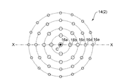
- FIG. 2 is a plan view showing an arrangement layout of a plurality of introduction holes provided in the partition wall of FIG. 1 from the central axis side. It is a modification of FIG. It is sectional drawing which shows the whole filter apparatus structure concerning a prior art example.
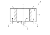
- FIG. 1 is a cross-sectional view showing an overall configuration of a filter device 1 according to at least one embodiment of the present invention.
- the filter device 1 is a device that purifies the gas supplied to the intake port of the gas compressor by being attached to a gas compressor (not shown).
- the casing 2 has a substantially cylindrical shape along the central axis C, and has a housing portion 6 that houses the filter element 4.
- An inlet portion 8 for introducing gas into the housing portion 6 is provided on the upstream side of the housing portion 6.
- an outlet portion 10 for discharging the gas that has passed through the filter element 4 in the housing portion 6 is provided on the downstream side of the housing portion 6.
- the inlet portion 8 is formed as an opening formed in a ring shape around the central axis C in the circumferential direction on one end face of the casing 2 having a substantially cylindrical shape.
- a negative pressure is generated on the downstream side of the filter device 1
- an air flow as indicated by an arrow in FIG. 1 is generated in the inlet portion 8, and the gas is introduced into the accommodating portion 6.
- the outlet portion 10 is provided on the end surface of the casing 2 where the inlet portion 8 is provided, and the gas that has passed through the filter element 4 in the accommodating portion 6 is discharged toward the downstream side.
- the layout of the inlet part 8 and the outlet part 10 in such a casing 2 is only an example, and is not limited in the range which does not prevent implementation of this invention.
- the accommodating portion 6 has an internal space for accommodating the filter element 4.
- the filter element 4 is disposed on the downstream side of the inlet portion 8 and the upstream side of the outlet portion 10 in the internal space of the accommodating portion 6.
- the filter element 4 is a filter medium for purifying the gas taken in from the inlet portion 8 and has a substantially cylindrical shape along the circumferential direction so as to surround the central axis C. Thereby, the gas taken into the casing 2 from the inlet portion 8 is configured to be discharged from the outlet portion 10 to the gas compressor side after passing through the filter element 4 accommodated in the accommodating portion 6.
- the outlet part 10 has a compression chamber 12 provided on the downstream side of the accommodating part 6.
- the compression chamber 12 is configured as an end surface of the casing 2, a partition wall 14 that separates the accommodating portion 6 and the compression chamber 12, and a separate member from the casing 2 on the downstream side of the partition wall 14.
- the outlet side member 20 is provided on the downstream side of the first portion 20a and the first portion 20a defining the compression chamber 12 together with the partition wall 14 which is a part of the casing 2, and is attached to the intake port of the gas compressor.
- Possible second portion 20b Possible second portion 20b.
- the first portion 20a and the second portion 20b each have a substantially cylindrical shape along the central axis C.
- the first portion 20 a forms the compression chamber 12 together with the partition wall 14.
- the partition wall 14 is constituted by a plurality of introduction holes 16 formed in the partition wall 14 so as to communicate the accommodating portion 6 and the compression chamber 12.
- the plurality of introduction holes 16 are provided so that the gas passing through them is jetted, and open toward the compression region 18 set in the compression chamber 12.
- the compression region 18 is set as a part of the compression chamber 12, and in particular, is set narrower than the region where the plurality of introduction holes 16 are provided in the partition wall 14. Therefore, the gas that has passed through the filter element 4 is ejected as a jet from the plurality of introduction holes 16 toward the compression region 18 and collides locally with each other in the compression region 18. In this way, collision compression is effectively performed.
- FIG. 4 is a cross-sectional view showing the overall configuration of a filter device 1 'according to a conventional example.
- portions corresponding to those of the filter device 1 according to the present embodiment are denoted by common reference numerals, and redundant descriptions are omitted as appropriate.
- the gas taken in from the inlet portion 8 causes a pressure loss due to ventilation resistance or friction with the wall surface of the casing 2 when passing through the filter element 4 of the housing portion 6.
- the pressure can be increased by causing the gases ejected from the plurality of introduction holes 16 to collide with each other, so that such pressure loss is reduced.
- the gas pressure after passing through the filter device 1 can be positively improved.
- the collision compression in the exit part 10 can be performed without changing the structure of the upstream part of the exit part 10 so that FIG.1 and FIG.4 may be compared, the purification performance of the filter apparatus 1 can be performed. The above action can be obtained while maintaining the above.
- the compression chamber 12 in which the collisional compression of the gases ejected as jets from the plurality of introduction holes 16 is performed is formed so as to have a smaller volume than the accommodating portion 6. Thereby, it can suppress that a pressure falls because the gas which the pressure rose by the collision compression in the compression chamber 12 disperse
- the outlet side member 20 has a two-stage structure because the second portion 20b is formed to have a smaller diameter than the first portion 20a (the second portion 20b has a smaller volume than the first portion 20a). Have. As a result, the gas sent out from the compression chamber 12 is further suppressed from being dispersed, and the gas with less pressure loss can be supplied from the filter device 1.
- region 18 where the collision compression of gas is performed is set so that the area
- FIG. 2 is a plan view showing the arrangement layout of the plurality of introduction holes 16 provided in the partition wall 14 of FIG. 1 from the central axis C side (note that FIG. 1 corresponds to a cross section taken along line XX of FIG. 2). Shows a cross section).
- the plurality of introduction holes 16 are provided concentrically with respect to the central axis C.
- a plurality of introduction holes 16 are arranged in the circumferential direction and the radial direction with respect to the central axis C, and each group of 16a, 16b, 16c, 16d, and 16e is sequentially arranged from the side closer to the central axis C.
- Each is provided concentrically with respect to the central axis C.
- FIG. 2 shows the case where the opening diameters of the introduction holes 16 are the same, but the opening diameters of the introduction holes 16 may be different as shown in FIG.
- the plurality of introduction holes 16 are formed so that the opening diameter decreases from the inner side to the outer side in the radial direction. Since the introduction hole 16 on the radially outer side has a longer distance to the compression region 18 than the introduction hole 16 on the radially inner side, the jet flow when reaching the compression region 18 tends to be weak.
- exit side member 20 may be comprised integrally with the casing 2.
- the energy consumption per unit gas amount of the gas compressor when mounted on the intake port of the gas compressor, the energy consumption per unit gas amount of the gas compressor is reduced by realizing good volume efficiency.
- a possible filter device can be provided.
- the present disclosure can be used for a filter device that can be attached to an intake port of a gas compressor.
Landscapes
- Engineering & Computer Science (AREA)
- Mechanical Engineering (AREA)
- General Engineering & Computer Science (AREA)
- Compressor (AREA)
- Structures Of Non-Positive Displacement Pumps (AREA)
Abstract
L'invention concerne un dispositif de filtre pourvu i) d'un élément de filtre et ii) d'un boîtier présentant une partie de réception destinée à recevoir l'élément de filtre. Une pluralité de trous d'introduction sont ménagés dans une paroi de séparation avec la partie de réception au niveau d'une partie de sortie sur le côté aval de la partie de réception. Les trous d'introduction sont conçus de façon à s'ouvrir vers une région de compression placée dans une chambre de compression, des gaz éjectés depuis les trous d'introduction entrant en collision l'un avec l'autre.
Applications Claiming Priority (2)
| Application Number | Priority Date | Filing Date | Title |
|---|---|---|---|
| JP2017-017084 | 2017-02-01 | ||
| JP2017017084A JP2018123774A (ja) | 2017-02-01 | 2017-02-01 | フィルタ装置 |
Publications (1)
| Publication Number | Publication Date |
|---|---|
| WO2018143234A1 true WO2018143234A1 (fr) | 2018-08-09 |
Family
ID=63039644
Family Applications (1)
| Application Number | Title | Priority Date | Filing Date |
|---|---|---|---|
| PCT/JP2018/003096 Ceased WO2018143234A1 (fr) | 2017-02-01 | 2018-01-31 | Dispositif de filtre |
Country Status (2)
| Country | Link |
|---|---|
| JP (1) | JP2018123774A (fr) |
| WO (1) | WO2018143234A1 (fr) |
Citations (5)
| Publication number | Priority date | Publication date | Assignee | Title |
|---|---|---|---|---|
| JPS4937883U (fr) * | 1972-07-06 | 1974-04-03 | ||
| JPS5528473U (fr) * | 1978-08-14 | 1980-02-23 | ||
| JPH0319534U (fr) * | 1989-07-04 | 1991-02-26 | ||
| US5205849A (en) * | 1992-06-29 | 1993-04-27 | Ransburg Corporation | Air filter having a low internal pressure drop |
| JPH1122644A (ja) * | 1997-07-02 | 1999-01-26 | Uekura:Kk | エアポンプ用吸気口の構造 |
-
2017
- 2017-02-01 JP JP2017017084A patent/JP2018123774A/ja active Pending
-
2018
- 2018-01-31 WO PCT/JP2018/003096 patent/WO2018143234A1/fr not_active Ceased
Patent Citations (5)
| Publication number | Priority date | Publication date | Assignee | Title |
|---|---|---|---|---|
| JPS4937883U (fr) * | 1972-07-06 | 1974-04-03 | ||
| JPS5528473U (fr) * | 1978-08-14 | 1980-02-23 | ||
| JPH0319534U (fr) * | 1989-07-04 | 1991-02-26 | ||
| US5205849A (en) * | 1992-06-29 | 1993-04-27 | Ransburg Corporation | Air filter having a low internal pressure drop |
| JPH1122644A (ja) * | 1997-07-02 | 1999-01-26 | Uekura:Kk | エアポンプ用吸気口の構造 |
Also Published As
| Publication number | Publication date |
|---|---|
| JP2018123774A (ja) | 2018-08-09 |
Similar Documents
| Publication | Publication Date | Title |
|---|---|---|
| CN102985695B (zh) | 多级低压降消声器 | |
| RU2002107872A (ru) | Способ распыления топлива воздушным потоком, топливная насадка (варианты) и топливный инжектор для осуществления способа | |
| US4325459A (en) | Muffler diffuser | |
| CN104583554B (zh) | 消音器 | |
| KR101946323B1 (ko) | 가스계 소화 설비용의 소음 기능을 갖는 분사 헤드 | |
| JP2008025579A5 (fr) | ||
| JP2005069228A (ja) | マフラ | |
| WO2018157337A1 (fr) | Tête de ventilateur et ventilateur sans pales | |
| US20100278635A1 (en) | Noise attenuation device for a centrifugal compressor discharge or suction nozzle | |
| JP2018123774A (ja) | フィルタ装置 | |
| EP3278934B1 (fr) | Outil pneumatique doté d'un dispositif silencieux de type helmholtz | |
| CN103195549B (zh) | 一种消声器隔板及消声器 | |
| CN112096609B (zh) | 一种内置多孔消声器旋片电子抽气泵 | |
| KR100738480B1 (ko) | 산소발생장치용 소음기 | |
| CN216790308U (zh) | 吸油烟机用出风口罩及应用其的吸油烟机 | |
| CN108025730B (zh) | 消声系统 | |
| AU2016321952A1 (en) | Air intake device for combustion apparatus | |
| KR20130104693A (ko) | 배기가스 저감장치 | |
| KR20090011802U (ko) | 유동 균일화를 위한 디퓨져 구조를 가지는 소음기 | |
| KR200311997Y1 (ko) | 압축기용 소음기 | |
| JP4934829B2 (ja) | エンジンユニット | |
| JP6806663B2 (ja) | マフラー装置 | |
| CN219979142U (zh) | 消声机构 | |
| KR20040066214A (ko) | 압축기용 소음기 | |
| CN119616827B (zh) | 压缩机及制冷设备 |
Legal Events
| Date | Code | Title | Description |
|---|---|---|---|
| 121 | Ep: the epo has been informed by wipo that ep was designated in this application |
Ref document number: 18748468 Country of ref document: EP Kind code of ref document: A1 |
|
| NENP | Non-entry into the national phase |
Ref country code: DE |
|
| 122 | Ep: pct application non-entry in european phase |
Ref document number: 18748468 Country of ref document: EP Kind code of ref document: A1 |