WO2018150721A1 - コークス乾式消火設備 - Google Patents
コークス乾式消火設備 Download PDFInfo
- Publication number
- WO2018150721A1 WO2018150721A1 PCT/JP2017/045634 JP2017045634W WO2018150721A1 WO 2018150721 A1 WO2018150721 A1 WO 2018150721A1 JP 2017045634 W JP2017045634 W JP 2017045634W WO 2018150721 A1 WO2018150721 A1 WO 2018150721A1
- Authority
- WO
- WIPO (PCT)
- Prior art keywords
- bucket
- coke
- rail
- tower
- winding
- Prior art date
- Legal status (The legal status is an assumption and is not a legal conclusion. Google has not performed a legal analysis and makes no representation as to the accuracy of the status listed.)
- Ceased
Links
Images


Classifications
-
- C—CHEMISTRY; METALLURGY
- C10—PETROLEUM, GAS OR COKE INDUSTRIES; TECHNICAL GASES CONTAINING CARBON MONOXIDE; FUELS; LUBRICANTS; PEAT
- C10B—DESTRUCTIVE DISTILLATION OF CARBONACEOUS MATERIALS FOR PRODUCTION OF GAS, COKE, TAR, OR SIMILAR MATERIALS
- C10B39/00—Cooling or quenching coke
- C10B39/02—Dry cooling outside the oven
-
- Y—GENERAL TAGGING OF NEW TECHNOLOGICAL DEVELOPMENTS; GENERAL TAGGING OF CROSS-SECTIONAL TECHNOLOGIES SPANNING OVER SEVERAL SECTIONS OF THE IPC; TECHNICAL SUBJECTS COVERED BY FORMER USPC CROSS-REFERENCE ART COLLECTIONS [XRACs] AND DIGESTS
- Y02—TECHNOLOGIES OR APPLICATIONS FOR MITIGATION OR ADAPTATION AGAINST CLIMATE CHANGE
- Y02P—CLIMATE CHANGE MITIGATION TECHNOLOGIES IN THE PRODUCTION OR PROCESSING OF GOODS
- Y02P20/00—Technologies relating to chemical industry
- Y02P20/10—Process efficiency
- Y02P20/129—Energy recovery, e.g. by cogeneration, H2recovery or pressure recovery turbines
Definitions
- the present invention relates to a coke dry fire extinguishing equipment that transports and cools red hot coke generated by carbonizing coal in a coke oven to a coke cooling tower.
- red hot coke generated by carbonizing coal in the coking chamber of the coke oven is pushed out of the coke oven kiln and the fire extinguisher rail provided along the coke oven is used. It is received by a transport bucket towered on a traveling carriage.
- the transport bucket receiving the reddish coke is mounted on a carriage, moves to the hoisting tower, and is lifted to a position higher than the coke cooling tower.
- the lifted conveyance bucket moves above the coke cooling tower, and the red hot coke in the conveyance bucket is charged into the coke cooling tower.
- the red hot coke charged in the coke cooling tower is cooled by the circulating gas, and the sensible heat is recovered as steam.
- the transport bucket receiving the red hot coke is mounted on the carriage and transported to the hoisting tower.
- the traverser system described in the background art section of Patent Document 1 is used.
- the traverser system is a fire extinguisher installed along the coke oven by installing a hoisting tower at a location slightly away from the coke oven, providing a traverse facility for moving the carriage with the carrying buckets to the hoisting tower. This is a method involving a horizontal movement in a direction away from the vehicle rail.
- the required processing amount of the CDQ facility is determined by the production amount of the coke oven to be processed. Specifically, in consideration of the actual operation time, it depends on the number of coke ovens that must be processed per unit time and the amount of coke discharged per one coke oven. Knowing the number of kilns that must be processed per unit time determines the charging cycle time, but if you want to increase the processing capacity of the cooling tower, the number of times that you must charge per unit operating time increases. In other words, the constraint condition is that the necessity (constraint) of shortening the charging cycle time occurs. In particular, when it is necessary to adopt a traverser system (addition of a traverse facility) in the layout of the entire CDQ facility, it becomes more difficult to increase the size of the cooling tower because the transport time of the transport bucket becomes longer. .
- the present invention has been made in order to solve such a problem, and provides a coke dry fire extinguishing equipment that can shorten the charging cycle time while adopting a traverser system, and can realize equipment having a large processing amount.
- the purpose is that.
- the coke dry fire extinguishing equipment according to the present invention is a coke dry fire extinguishing equipment that extinguishes and cools red hot coke taken out from a coke oven in which a pre-furnace rail is laid on the coke take-out side, and performs waste heat recovery.
- a single cooling tower installed at a position away from the front rail of the coke at the coke take-off side of the coke oven;
- a first furnace front carriage and a second furnace front carriage that are mounted on a child carriage on which a bucket for receiving the red hot coke is placed and travel on the furnace front rail;
- a first winding tower provided at a first winding position adjacent to the single cooling tower and provided with a guide rail extending vertically;
- a first hoisting device configured to be capable of hoisting the bucket along the guide rail of the first hoisting tower to a position higher than the top of the single cooling tower, and the hoisted bucket is suspended.
- a first hoisting machine comprising a first traveling carriage that is moved to a charging position set immediately above the top of the single cooling tower in a state; A first traverser rail laid between the furnace front rail and the first winding position, wherein the first furnace front cart or the second furnace front cart on the furnace front rail at a first delivery position.
- the child carriage with the bucket placed thereon is exchanged between the first carriage position and the first winding position, and the child carriage loaded with the bucket is reciprocated on the first traverser rail.
- a first traverser configured to be movable;
- the second winding provided with a guide rail that is installed at a second winding position adjacent to the single cooling tower on the opposite side of the first winding position across the single cooling tower and extends in the vertical direction Tower,
- a second winding configured to be able to wind up the bucket independently of the first hoisting machine along the guide rail of the second upper tower to a position higher than the top of the single cooling tower.
- An upper device, and a second hoisting machine including a second traveling carriage that moves to a charging position set immediately above the top of the single cooling tower in a state in which the wound bucket is suspended;
- the child cart with the bucket is transferred between the second traverser rail and the child cart with the bucket is reciprocated between the second transfer position and the second winding position on the second traverser rail.
- a second traverser configured to be movable; The top of the first upper tower and the second volume for causing the first traveling carriage and the second traveling carriage to travel to the charging position set immediately above the top of the single cooling tower.
- a top running rail constructed only between the top of the upper tower, During normal operation, all of the red hot coke in the bucket rolled up from the first upper tower and the red hot coke in the bucket rolled up from the second upper tower are installed in the single cooling tower. Configured to enter, When it is necessary to stop the bucket conveyance system of either the first winding boarding side or the second winding boarding side, the first winding boarding side and the second winding board It is configured so that operation can be performed by charging the red-cooled coke from the bucket transported by the other bucket transport system to the single cooling tower. It is.
- each of the first hoisting machine and the second hoisting machine is a rope trolley type hoisting machine.
- the first winding position, the single cooling tower, and the second winding position are parallel to the pre-furnace rail in plan view. It is characterized by being lined up.
- an interval between the first transfer position and the second transfer position is set such that the first furnace front carriage and the second transfer position
- the furnace front carriage is set so as not to interfere with each other when stopped in the first delivery position and the second delivery position.
- each of the first furnace front carriage and the second furnace front carriage is two connected vehicles, and each vehicle mounts the slave carriage. Including those configured to be An interval between the first transfer position and the second transfer position is set to be at least three times as long as the distance between the centers of the vehicles in a connected state.
- the single cooling tower has a processing capacity of 160 t / h or more. .
- the first hoisting machine and the second hoisting machine are provided with a hanging object for holding the bucket when lifting the bucket.
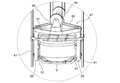
- the suspension includes a ceiling portion covering the upper portion of the bucket, a pair of arm portions provided to extend downward from the ceiling portion to hold the bucket, and a pulley provided on the ceiling portion. And in a plan view, the direction connecting the pair of arm portions and the axial direction of the rotating shaft of the pulley are arranged so as to be orthogonal to each other.
- the red hot coke in the bucket wound up from the first upper tower and the red hot coke in the bucket wound up from the second upper tower are all charged into a single cooling tower.
- the charging cycle time can be shortened, and a coke dry fire extinguishing equipment with a large throughput can be provided.
- the bucket transported by the other bucket transport system can be operated by charging red hot coke into a single cooling tower, causing trouble in one bucket transport system. In such a case, even when one bucket transport system is inspected, the operation frequency can be continued using the other bucket transport system although the charging frequency is reduced.
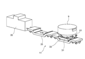
- FIG. 1 It is a top view of the coke dry-type fire extinguishing equipment concerning an embodiment of the invention. It is a perspective view of what removed the cooling tower among the coke dry fire extinguishing equipment shown in FIG. It is explanatory drawing of the 1st furnace front trolley
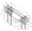
- FIG. 3 is an enlarged view showing a part including the tops of the first tower and the second tower of the coke dry fire extinguishing facility shown in FIG. 2 (part 2). It is explanatory drawing explaining arrangement
- a coke dry fire extinguishing facility 1 according to an embodiment of the present invention will be described with reference to the drawings.
- the coke dry fire extinguishing equipment 1 extinguishes and cools red coke taken out from a coke oven 5 in which a pre-furnace rail 3 is laid on the coke take-out side, and performs waste heat recovery.
- the machine 17, the first traverser 19, the second winding tower 21, the second winding machine 23, the second traverser 25, and the top traveling rail 27, the bucket wound up from the first winding tower 15 9 and the bucket 9 wound up from the second upper tower 21 are configured such that red hot coke can be alternately charged into the single cooling tower 7.
- each configuration will be described in detail.
- the single cooling tower 7 is installed at a position away from the furnace rail 3 on the coke extraction side of the coke oven 5.
- the cooling tower 7 is configured so that red hot coke is continuously charged from the top, the red hot coke is cooled by a circulating gas blown from the bottom, and the heat-recovered coke is continuously discharged from the bottom.
- the heat recovered in the cooling tower 7 is recovered in the form of steam in a boiler 29 (see FIG. 1) installed adjacent to the cooling tower 7.
- a coke dry fire extinguishing system that applies a traverser system to the bucket transport system, if multiple cooling towers are provided to increase the throughput, the number of incidental facilities such as associated boilers also increases, and it is necessary to maintain these incidental facilities.
- the increase in the processing amount can be realized by a configuration including a single cooling tower instead of a plurality of cooling towers, so that an increase in maintenance time accompanying an increase in the processing amount can be suppressed. .
- the processing capacity of the cooling tower 7 is not particularly limited, but by using a cooling tower having a high processing capacity (a large processing amount per unit time), a production amount that could not be processed without a plurality of cooling towers conventionally. It is possible to treat red hot coke taken from a large coke oven in a single cooling tower. Since the present invention is particularly effective when a traverser type bucket transport system is applied to such a cooling tower having a high processing capacity, the cooling tower 7 has a processing capacity of 160 t / h or more. Is preferred.
- First Furnace Cart and Second Furnace Cart The first furnace front carriage 11 and the second furnace front carriage 13 travel on the furnace front rail 3 with a child carriage 31 on which a bucket 9 receiving red hot coke is placed.
- each of the first furnace front carriage 11 and the second furnace front carriage 13 of the present embodiment includes two connected vehicles 33, and each vehicle 33 is a slave carriage 31. Is driven by the locomotive 35 and travels along the furnace rail 3. But the 1st furnace front trolley
- the child carriage 31 placed on the first furnace front carriage 11 and the second furnace front carriage 13 is placed and conveyed on the first furnace front carriage 11 and the second furnace front carriage 13, and the first traverser 19.
- the bucket 9 placed on the child carriage 31 serves as a support portion 61 when the both ends of the lower gate lift the bucket, and, as shown in FIG. (See FIG. 4).
- the first winding tower 15 is provided at a first winding position P1 adjacent to the cooling tower 7, and includes a guide rail 41 extending in the vertical direction.
- the first upper tower 15 is not shown except for the tower top and the guide rail 41.
- the first hoisting machine 17 of the present embodiment is a rope trolley hoisting machine as described in Japanese Patent No. 3233044, and cools the bucket 9 along the guide rail 41 of the first hoisting tower 15.
- the first hoisting device 43 configured to be able to wind up to a position higher than the top of the tower 7 and the bucket 9 that has been hoisted are run on the top running rail 27 and directly above the top of the cooling tower 7. And a self-propelled first traveling carriage 45 that is moved to the set charging position.
- the first hoisting device 43 is installed in the vicinity of the lower part of the first hoisting tower 15 and the first moving pulley 49 attached to the upper part of the first hoisting object 47 and the first hoisting tower 15.
- the first hanger 47 includes a ceiling portion 57 located above the bucket 9 and a pair of arm portions 59 that extend downward from the ceiling portion 57 and hold the bucket 9. And a hook portion 63 (see FIG. 5) for holding the bucket 9 by supporting the support portion 61 of the bucket 9 is provided at the lower end portion of the arm portion 59.
- the pair of first moving pulleys 49 is attached to the ceiling portion 57.
- the axial direction of the rotation shaft of the first moving pulley 49 and the pair of arm portions 59 are provided.
- the direction which connects is orthogonally arranged in planar view.
- the reason for this arrangement is as follows.
- a top traveling rail 27 is provided in parallel with the furnace front rail 3
- the first traveling carriage 45 travels in parallel with the furnace front rail 3. It is necessary to make the direction orthogonal to the furnace rail 3.
- the first traverser rail 37 is provided orthogonal to the furnace front rail 3, and a first hanging piece 47 disposed between the two guide rails 41 by moving the bucket along the first traverser rail 37.
- the two guide rails 41 are disposed so as to straddle the first traverser rail 37, and the arm portions 59 are also arranged in the same manner as the guide rails 41. Accordingly, the direction of the rotation axis of the first movable pulley 49 and the direction connecting the pair of arm portions 59 are orthogonal to each other.
- the arrangement of the arm part 59 and the first movable pulley 49 uses the first hanging object 47 as described above, so that the arm part 59 and the first moving pulley 49 extend to both sides of the cooling tower 7 in parallel to the furnace rail 3 as shown in FIG.
- a top traveling rail 27 is provided, and the bucket 9 conveyed by the first traverser 19 is wound up to the top of the first winding tower 15 by using the first hoisting machine 17, and the first traveling carriage 45 is used to cool the cooling tower 7. Can be transported up to
- the load of the bucket 9 is transmitted to the ceiling part 57 of the first hanging object 47 through the arm part 59 and the load in the lifting direction is transmitted from the first movable pulley 49, the arrangement as described above is performed.
- the load support point of the ceiling part 57 is shifted by approximately 90 °.
- the 1st moving pulley 49 is arrange
- the load which acts on the ceiling part 57 of the hanger 47 becomes large. Therefore, in the present embodiment, as shown in FIG. 4, the rigidity is enhanced by providing a plurality of rib members 65 on the ceiling portion 57 in a direction orthogonal to the direction of the rotation axis of the first movable pulley 49.
- the first traverser 19 includes a first traverser rail 37 laid between the furnace front rail 3 and the first winding position P1, and the furnace front rail at the first delivery position P2 (see FIGS. 1 and 2).
- the first and second front bogies 11 and 13 above and below the sub-bogie 31 on which the bucket 9 is placed are exchanged between the first and second bogies 11 and 13, and the bucket is placed between the first delivery position P2 and the first winding position P1.
- 9 is configured such that the child cart 31 on which the vehicle 9 is placed can be reciprocated on the first traverser rail 37.
- the first delivery position P ⁇ b> 2 means that the first bogie 11 or the second bogie 13 on the fore rail 3 is connected to the first traverser 19 with the child cart 31. It is a position to give and receive.
- the first winding position P1 is a lower position of the guide rail 41 on the first traverser rail 37 and is a position where the bucket 9 can be arranged to be lifted.
- the first traverser 19 of the present embodiment has a tow cart 67 that can be connected to the slave cart 31 as a mechanism for reciprocating the slave cart 31, and pulls the tow cart 67 with a wire rope (not shown).
- a wire rope not shown
- the child cart 31 is moved by being pulled by the towing cart 67.
- the first traverser 19 does not require a mechanism for causing the child cart 31 to travel.
- the second winding tower 21 is installed at a second winding position P3 adjacent to the single cooling tower 7 on the opposite side of the first winding position P1 across the cooling tower 7, and extends in the vertical direction. 41 is provided.
- a second constant pulley 79 a of the second hoisting machine 23 and a second constant pulley 79 b of the first hoisting machine 17 are attached to the top of the second hoisting tower 21.
- the second hoisting machine 23 is a rope trolley hoisting machine similar to the first hoisting machine 17, and the bucket 9 is connected to the guide rail 41 of the second hoisting tower 21 independently of the first hoisting machine 17.
- the second hoisting device 69 configured to be able to wind up to a position higher than the top of the cooling tower 7 along the top traveling rail 27 in a state where the wound bucket 9 is suspended, and the single cooling tower 7 And a second traveling carriage 71 that is moved to a charging position set immediately above the top of the vehicle.
- the second upper tower 23 is not shown except for the tower top and the guide rail 41.
- the second hoisting device 69 is installed in the vicinity of the lower part of the second hoisting tower 21, the second hanging pulley 73 attached to the upper part of the second hoisting object 73, and the second hoisting tower 73.
- a second fixed pulley 79c attached to the upper part of the second traveling carriage 71 and a second wire rope 81 wound around each pulley and wound and fed by the second hoisting drive device 75 are configured.
- the second hanging object 73 is configured in the same manner as the first hanging object 47.
- the arrangement of each pulley is arranged so that the first wire rope 55 on the first hoisting device 43 side and the second wire rope 81 on the second hoisting device 69 side do not interfere with each other. They are shifted in the direction. Specifically, as shown in FIGS. 6 and 7, the interval between the pulleys on the first hoisting device 43 side is increased, and the interval between the pulleys on the second hoisting device 69 side is reduced. Therefore, even if a rope trolley type hoisting machine is used as the two hoisting machines, the wire ropes can be arranged without interfering with each other.
- the second traverser 25 has the same configuration as that of the first traverser 19 and includes a second traverser rail 39 laid between the furnace front rail 3 and the second winding position P3. While sending and receiving the child carriage 31 with the bucket 9 placed between the first furnace front carriage 11 or the second furnace front carriage 13 on the furnace front rail 3, the second delivery position P4 and the second winding position P3 The child carriage 31 with the bucket 9 placed between them can be reciprocated on the second traverser rail 39.
- first furnace front carriage 11 and the second furnace front carriage 13 of the present embodiment are connected to two vehicles 33 on which the bucket 9 can be placed.
- the interval between the first delivery position P2 and the second delivery position P4 is such that the first furnace front carriage 11 and the second furnace front carriage 13 are closest to each other regardless of the number of vehicles to be pulled and the shape of the vehicle.
- the first and second delivery positions P2 and P4 are set so that they do not interfere even when stopped simultaneously. In the present embodiment, particularly, as shown in FIG.
- the distance L 2 between the first transfer position P2 and the second transfer position P4 (more precisely, the vehicle 33 stopped at the first transfer position P2) central and distance L 2) is between the center of the vehicle 33 stops at the second transfer position P4, greater than or equal to 3 times the distance L 1 between the center of the vehicle 33 in the coupled state, i.e. L 2 ⁇ 3L 1 is set.
- the first furnace front carriage 11 and the second furnace front carriage 13 are simultaneously stopped at the first delivery position P2 and the second delivery position P4, respectively, and Even if the vehicle 33 of the first fore-stage carriage 11 and the vehicle 33 of the second fore-stage carriage 13 are closest to each other, they do not interfere with each other.
- the 1st furnace front carriage 11 and the 2nd furnace front are respectively set to the 1st delivery position P2 and the 2nd delivery position P4.
- the carriage 13 can be stopped simultaneously.
- both of the two vehicles included in the first furnace front carriage 11 are freely arranged at the first transfer position P2, and the two vehicles included in the second furnace front carriage 12 are arranged. Any of the vehicles can be freely arranged at the second delivery position P4. Thereby, the freedom degree of conveyance becomes high and it can contribute to realization of shortening of a charging cycle time.
- the top traveling rail 27 is configured to allow the first traveling carriage 45 and the second traveling carriage 71 to travel to the charging position set immediately above the top of the cooling tower 7 and the second winding. It is constructed only between the top of the upper tower 21.
- each device As a whole>
- the first winding position P1, the single cooling tower 7, and the second winding position P3 are parallel to the furnace rail 3 in plan view.
- the two traveling carriages travel in opposite directions.
- positioning the full length of two traverser rails can be suppressed to the minimum.
- each of the first hoisting machine and the second hoisting machine is a rope trolley type hoisting machine, even if the hoisting drive device is installed on the ground, it can be prevented from interfering with other equipment. .
- the operation of the coke dry fire extinguishing equipment 1 configured as described above will be described focusing on the charging cycle time.
- the first furnace carriage 11 travels along the furnace front rail 3 and moves to the first delivery position P2.
- the child carriage 31 on which the bucket 9 is mounted is moved to the first traverser rail 37 side and moved to the first winding position P1 on the first traverser rail 37.
- the bucket 9 is held by the first hanging piece 47 and is lifted along the guide rail 41 to a predetermined position higher than the cooling tower 7.
- the first traveling carriage 45 travels on the furnace top traveling rail and moves to the charging position of the red hot coke set just above the cooling tower 7, and at this charging position.
- the red hot coke in the bucket 9 is charged into the cooling tower 7.
- the bucket 9 emptied by charging the red hot coke into the cooling tower 7 moves on the reverse route to the above and is mounted on the first furnace front carriage 11 to receive the red hot coke newly taken out from the kiln. Then, the above route is further moved and reddish coke is charged into the cooling tower 7 repeatedly.
- the second furnace front carriage 13 travels on the furnace front rail 3 and moves to the second delivery position P4.
- the child carriage 31 on which the bucket 9 is mounted is moved to the second traverser rail 39 side and moved to the second winding position P3 on the second traverser rail 39.
- the bucket 9 is held by the second hanging object 73 and is lifted along the guide rail 41 to a predetermined position higher than the cooling tower 7.
- the second traveling carriage 71 travels on the furnace top traveling rail and moves to the charging position of the red hot coke set just above the cooling tower 7, and at this charging position.
- the red hot coke in the bucket 9 is charged into the cooling tower 7.
- the bucket 9 emptied by charging the red hot coke into the cooling tower 7 moves on the reverse route to the above and is mounted on the second furnace front carriage 13 to receive the red hot coke newly taken out from the kiln. Then, the above route is further moved and reddish coke is charged into the cooling tower 7 repeatedly.
- the red hot coke in the bucket 9 wound up from the first upper tower 15 and the bucket 9 wound up from the second upper tower 21 are used. All of the red hot coke is charged into a single cooling tower 7. Therefore, it is possible to charge red hot coke alternately from the bucket 9 wound up from the first upper tower 15 and the bucket 9 wound up from the second upper tower 21.
- the charging cycle time can be reduced to about a maximum as compared with the case where there is only one winding tower in FIG. 9 (a). Can be halved.
- the bucket transport system on the first winding tower 15 side includes the first traverser 19, the first hoisting machine 17, and the first traveling carriage 45.
- the bucket transportation system on the second winding tower 21 side includes Includes the second traverser 25, the second hoisting machine 23, and the second traveling carriage 71.
- a rope trolley type hoisting machine is used as the hoisting machines 17 and 23 for lifting the bucket 9 on the upper parts of the hoisting towers 15 and 21. Since the first hoisting drive device 51 and the second hoisting drive device 75 constituting the device 69 can be installed on, for example, a fixed floor provided on the ground without being provided at the upper part of the hoisting towers 15, 21, As compared with the above, the first traveling carriage 45 and the second traveling carriage 71 arranged at the upper part of the hoisting towers 15 and 21 can be significantly reduced in weight.
- the first hoisting device 43 and the second hoisting device 69 of the present invention are not limited to the rope trolley type hoisting machine, and may be a top crane provided in the first traveling carriage 45 and the second traveling carriage 71.
Landscapes
- Chemical & Material Sciences (AREA)
- Engineering & Computer Science (AREA)
- Materials Engineering (AREA)
- Oil, Petroleum & Natural Gas (AREA)
- Organic Chemistry (AREA)
- Coke Industry (AREA)
Abstract
トラバーサ方式を採用しながらも装入サイクルタイムを短くでき、処理量の大きなコークス乾式消火設備を提供する。 本発明に係るコークス乾式消火設備1は、コークス取出側に炉前軌条3が敷設されたコークス炉5から取り出される赤熱コークスを消火及び冷却すると共に、廃熱回収を行うものであって、単一の冷却塔7と、赤熱コークスを受骸するバケット9を搬送する第1炉前台車11及び第2炉前台車13と、第1巻上塔15と、第1巻上機17と、第1トラバーサ19と、第2巻上塔21と、第2巻上機23と、第2トラバーサ25と、頂部走行軌条27とを備え、第1巻上塔15から巻き上げたバケット9と、第2巻上塔21から巻き上げたバケット9とから単一の冷却塔7に対して交互に赤熱コークスを装入することができるよう構成されている。
Description
本発明は、コークス炉で石炭を乾留して生成された赤熱コークスをコークス冷却塔に搬送して冷却するコークス乾式消火設備に関する。
コークス乾式消火(CDQ)設備においては、コークス炉の炭化室で石炭を乾留して生成される赤熱コークスは、コークス炉の窯口から押し出されて、コークス炉に沿って設けられた消火車軌条を走行する台車上に塔載された搬送バケットに受骸される。
赤熱コークスを受骸した搬送バケットは台車に塔載されて巻上塔まで移動してコークス冷却塔よりも高い位置まで吊り上げられる。吊り上げられた搬送バケットは、コークス冷却塔の上方に移動して、搬送バケット内の赤熱コークスがコークス冷却塔に装入される。コークス冷却塔に装入された赤熱コークスは、循環ガスによって冷却され、その顕熱が蒸気として回収される。
赤熱コークスを受骸した搬送バケットは台車に塔載されて巻上塔まで移動してコークス冷却塔よりも高い位置まで吊り上げられる。吊り上げられた搬送バケットは、コークス冷却塔の上方に移動して、搬送バケット内の赤熱コークスがコークス冷却塔に装入される。コークス冷却塔に装入された赤熱コークスは、循環ガスによって冷却され、その顕熱が蒸気として回収される。
上記のように、赤熱コークスを受骸した搬送バケットは台車に塔載されて巻上塔まで搬送されるが、この搬送方法として例えば特許文献1の背景技術の欄に記載されているトラバーサ方式が知られている。トラバーサ方式とは、巻上塔をコークス炉から少し離れた場所に設置し、搬送バケットを塔載した台車を巻上塔まで移動させるためのトラバース設備を設け、コークス炉に沿って設けられた消火車軌条から離れる方向への水平方向の移動を伴う方式である。
トラバーサ方式の場合には、消火車軌条から離れる方向へ搬送バケットを移動させるので、搬送バケットの吊り上げに際して他の機器類との干渉が問題となることはない。また、冷却塔を消火車軌条の直近に設ける必要もなく、冷却塔の設置位置等、CDQ設備全体のレイアウトの自由度を高くすることができる。
その一方で、トラバーサ方式の場合には、搬送バケットを横引きしてから吊り上げることになるため、コークス炉から赤熱コークスを搬送バケット内に受骸してから、搬送バケットを冷却塔の上方まで搬送して冷却塔に赤熱コークスを装入するまでに要する時間(搬送バケットの搬送時間)が長くなり、これにより搬送バケットから冷却塔への赤熱コークス装入のサイクルタイム(装入サイクルタイム)が長くなるという問題がある。
その一方で、トラバーサ方式の場合には、搬送バケットを横引きしてから吊り上げることになるため、コークス炉から赤熱コークスを搬送バケット内に受骸してから、搬送バケットを冷却塔の上方まで搬送して冷却塔に赤熱コークスを装入するまでに要する時間(搬送バケットの搬送時間)が長くなり、これにより搬送バケットから冷却塔への赤熱コークス装入のサイクルタイム(装入サイクルタイム)が長くなるという問題がある。
CDQ設備の必要処理量は、処理対象となるコークス炉の生産量によって決まる。具体的には、実操業時間を考慮し、単位時間あたりに処理しなければならないコークス炉の窯の数と、コークス炉の1窯あたりの排出コークス量とによって決まる。
単位時間あたりに処理しなければならない窯の数が分かると、装入サイクルタイムが決まるが、冷却塔の処理容量を大きくしたい場合には、単位操業時間あたりに装入しなければならない回数が増えることになり、装入サイクルタイムを短縮する必要(制約)が生じることが制約条件となる。特に、CDQ設備全体のレイアウト上、トラバーサ方式を採用する(トラバース設備を追加する)必要がある場合は、搬送バケットの搬送時間が長くなってしまうため、冷却塔を大型化することは一層難しくなる。
単位時間あたりに処理しなければならない窯の数が分かると、装入サイクルタイムが決まるが、冷却塔の処理容量を大きくしたい場合には、単位操業時間あたりに装入しなければならない回数が増えることになり、装入サイクルタイムを短縮する必要(制約)が生じることが制約条件となる。特に、CDQ設備全体のレイアウト上、トラバーサ方式を採用する(トラバース設備を追加する)必要がある場合は、搬送バケットの搬送時間が長くなってしまうため、冷却塔を大型化することは一層難しくなる。
本発明はかかる課題を解決するためになされたものであり、トラバーサ方式を採用しながらも装入サイクルタイムの短縮を可能とし、処理量の大きな設備も実現可能とするコークス乾式消火設備を提供することを目的としている。
(1)本発明に係るコークス乾式消火設備は、コークス取出側に炉前軌条が敷設されたコークス炉から取り出される赤熱コークスを消火及び冷却すると共に、廃熱回収を行うコークス乾式消火設備であって、
前記コークス炉の前記コークス取出側において前記炉前軌条から離れた位置に設置された単一の冷却塔と、
前記赤熱コークスを受けるバケットを載せる子台車を載置して前記炉前軌条上を走行する第1炉前台車及び第2炉前台車と、
前記単一の冷却塔に隣接する第1巻上位置に設置され、垂直方向に延びるガイドレールを備える第1巻上塔と、
前記バケットを前記第1巻上塔の前記ガイドレールに沿って前記単一の冷却塔の頂部よりも高い位置まで巻き上げ可能に構成された第1巻上装置、及び巻き上げられた前記バケットを吊った状態で前記単一の冷却塔の前記頂部の直上に設定された装入位置に移動させる第1走行台車を備える第1巻上機と、
前記炉前軌条と前記第1巻上位置との間に敷設された第1トラバーサ軌条を備え、第1授受位置にて前記炉前軌条上の前記第1炉前台車又は前記第2炉前台車との間で前記バケットを載せた前記子台車を授受するとともに、前記第1授受位置と前記第1巻上位置との間で前記バケットを載せた前記子台車を前記第1トラバーサ軌条上で往復移動させることができるよう構成された第1トラバーサと、
前記単一の冷却塔を挟んで前記第1巻上位置とは反対側で前記単一の冷却塔に隣接する第2巻上位置に設置され、垂直方向に延びるガイドレールを備える第2巻上塔と、
前記第1巻上機とは独立して前記バケットを前記第2巻上塔の前記ガイドレールに沿って前記単一の冷却塔の前記頂部よりも高い位置まで巻き上げ可能に構成された第2巻上装置、及び巻き上げられた前記バケットを吊った状態で前記単一の冷却塔の前記頂部の直上に設定された装入位置に移動させる第2走行台車を備える第2巻上機と、
前記炉前軌条と前記第2巻上位置との間に敷設された第2トラバーサ軌条を備え、第2授受位置にて前記炉前軌条上の前記第1炉前台車又は前記第2炉前台車との間で前記バケットを載せた前記子台車を授受するとともに、前記第2授受位置と前記第2巻上位置との間で前記バケットを載せた前記子台車を前記第2トラバーサ軌条上で往復移動させることができるよう構成された第2トラバーサと、
前記第1走行台車及び前記第2走行台車を前記単一の冷却塔の前記頂部の直上に設定された前記装入位置に走行させるための、前記第1巻上塔の頂部と前記第2巻上塔の頂部との間のみに架設された頂部走行軌条と、を備え、
通常操業時には、前記第1巻上塔から巻き上げた前記バケット内の前記赤熱コークスと、前記第2巻上塔から巻き上げた前記バケット内の前記赤熱コークスとの全てを前記単一の冷却塔に装入するよう構成されているとともに、
前記第1巻上搭側と前記第2巻上搭側とのうちのいずれか一方のバケット搬送系を停止する必要が生じた際には、前記第1巻上搭側と前記第2巻上搭側とのうちの他方のバケット搬送系で搬送された前記バケットから前記単一の冷却塔に対して前記赤熱コークスを装入することで操業ができるよう構成されていることを特徴とするものである。
(2)また、上記(1)に記載のものにおいて、前記第1巻上機及び前記第2巻上機のそれぞれがロープトロリー式巻上機であることを特徴とするものである。
(3)また、上記(1)又は(2)に記載のものにおいて、前記第1巻上位置、前記単一の冷却塔、前記第2巻上位置が、平面視で前記炉前軌条と平行に並んでいることを特徴とするものである。
(4)また、上記(1)~(3)のいずれかに記載のものにおいて、前記第1授受位置と前記第2授受位置との間の間隔が、前記第1炉前台車及び前記第2炉前台車が前記第1授受位置及び前記第2授受位置でそれぞれ停止した状態において、互いに干渉しないよう設定されていることを特徴とするものである。
(5)また、上記(4)に記載のものにおいて、前記第1炉前台車及び前記第2炉前台車のそれぞれが、連結された2両の車両であって各車両が前記子台車を載置可能に構成されているものを含み、
前記第1授受位置と前記第2授受位置との間の間隔が、連結状態にある前記車両の中央間の間隔の3倍以上に設定されていることを特徴とするものである。
前記第1授受位置と前記第2授受位置との間の間隔が、連結状態にある前記車両の中央間の間隔の3倍以上に設定されていることを特徴とするものである。
(6)また、上記(1)~(5)のいずれかに記載のものにおいて、前記単一の冷却塔が、160t/h以上の処理能力を有していることを特徴とするものである。
(7)また、上記(1)~(6)のいずれかに記載のものにおいて、前記第1巻上機及び前記第2巻上機は、前記バケットを吊り上げる際にバケットを保持する吊金物を有し、該吊金物は前記バケットの上方を覆う天井部と、該天井部から下方に延出するように設けられて前記バケットを保持する一対のアーム部と、前記天井部に設けられた滑車とを備え、平面視において前記一対のアーム部を繋ぐ方向と滑車の回転軸の軸方向とが直交するように配置されていることを特徴とするものである。
本発明においては、通常操業時には、第1巻上塔から巻き上げたバケット内の赤熱コークスと、前記第2巻上塔から巻き上げたバケット内の赤熱コークスとの全てを単一の冷却塔に装入するよう構成されているので、トラバーサ方式を採用しながらも装入サイクルタイムを短くでき、処理量の大きなコークス乾式消火設備を提供することができる。また、第1巻上搭側と第2巻上搭側とのうちのいずれか一方のバケット搬送系を停止する必要が生じた際には、第1巻上搭側と第2巻上搭側とのうちの他方のバケット搬送系で搬送されたバケットから単一の冷却塔に対して赤熱コークスを装入することで操業ができるよう構成されているため、一方のバケット搬送系にトラブルが生じた場合や、一方のバケット搬送系の点検を行う場合等にも、装入頻度は下がってしまうが他方のバケット搬送系を用いて操業の継続が可能である。
本発明の一実施形態のコークス乾式消火設備1について、図面を参照しながら説明する。コークス乾式消火設備1は、コークス取出側に炉前軌条3が敷設されたコークス炉5から取り出される赤熱コークスを消火及び冷却すると共に、廃熱回収を行うものであって、図1、図2に示すように、単一の冷却塔7と、赤熱コークスを受骸するバケット9を搬送する第1炉前台車11及び第2炉前台車13と、第1巻上塔15と、第1巻上機17と、第1トラバーサ19と、第2巻上塔21と、第2巻上機23と、第2トラバーサ25と、頂部走行軌条27とを備え、第1巻上塔15から巻き上げたバケット9と、第2巻上塔21から巻き上げたバケット9とから単一の冷却塔7に対して交互に赤熱コークスを装入することができるよう構成されている。
以下、各構成を詳細に説明する。
以下、各構成を詳細に説明する。
<冷却塔>
単一の冷却塔7は、コークス炉5のコークス取出側において炉前軌条3から離れた位置に設置されている。
冷却塔7は、上部から赤熱コークスが連続的に装入され、装入された赤熱コークスを下部から吹き込まれる循環ガスで冷却し、熱回収されたコークスを底部から連続的に排出するように構成されている。冷却塔7で回収された熱は冷却塔7に隣接して設置されたボイラ29(図1参照)で蒸気の形で回収される。
バケット搬送系にトラバーサ方式を適用したコークス乾式消火設備において、処理量を増大させるために冷却塔を複数設けると、付随するボイラ等の付帯設備の数も増加し、それらの付帯設備の保守に要する時間も長くなる。本発明においては、処理量の増大を複数の冷却塔で行うのではなく単一の冷却塔を備える構成で実現することができるため、処理量の増大に伴う保守時間の増大を抑えることができる。
冷却塔7の処理能力は特に限定されないが、処理能力が高い(単位時間当たりの処理量が大きい)冷却塔を使用することにより、従来複数の冷却塔を備えなければ処理しきれなかった生産量の大きなコークス炉から取り出される赤熱コークスを単一の冷却塔で処理することが可能となる。本発明は、このような処理能力の高い冷却塔にトラバーサ方式のバケット搬送系を適用する場合に特に大きな効果があることから、冷却塔7は160t/h以上の処理能力を有していることが好ましい。
<第1炉前台車及び第2炉前台車>
第1炉前台車11及び第2炉前台車13は、赤熱コークスを受けるバケット9を載せる子台車31を載置して炉前軌条3上を走行するものである。
第1炉前台車11及び第2炉前台車13は、赤熱コークスを受けるバケット9を載せる子台車31を載置して炉前軌条3上を走行するものである。
本実施の形態の第1炉前台車11及び第2炉前台車13のそれぞれは、図1~図3に示すように、連結された2両の車両33を備え、各車両33が子台車31を載置可能に構成され、機関車35に牽引されて炉前軌条3を走行する。もっとも、本発明の第1炉前台車11及び第2炉前台車13は2両連結のものに限定されない。
第1炉前台車11及び第2炉前台車13に載置される子台車31は、第1炉前台車11及び第2炉前台車13に載置されて搬送されると共に、第1トラバーサ19の第1トラバーサ軌条37及び第2トラバーサの第2トラバーサ軌条39を走行する。
子台車31に載置されるバケット9は、下部ゲートの両端部がバケットを吊りあげる際の支持部61となっており、図3に示すように、吊り上げ時に後述の吊金物47のアーム部59(図4参照)によって支持される。
子台車31に載置されるバケット9は、下部ゲートの両端部がバケットを吊りあげる際の支持部61となっており、図3に示すように、吊り上げ時に後述の吊金物47のアーム部59(図4参照)によって支持される。
<第1巻上塔>
第1巻上塔15は、冷却塔7に隣接する第1巻上位置P1に設置され、垂直方向に延びるガイドレール41を備えている。
第1巻上塔15の塔頂部には、後述する第1巻上機17の第1定滑車53a及び第2巻上機23の第2定滑車79bが取り付けられている。
なお、図2において、第1巻上塔15は塔頂部とガイドレール41以外は図示が省略されている。
第1巻上塔15は、冷却塔7に隣接する第1巻上位置P1に設置され、垂直方向に延びるガイドレール41を備えている。
第1巻上塔15の塔頂部には、後述する第1巻上機17の第1定滑車53a及び第2巻上機23の第2定滑車79bが取り付けられている。
なお、図2において、第1巻上塔15は塔頂部とガイドレール41以外は図示が省略されている。
<第1巻上機>
本実施の形態の第1巻上機17は、特許第3233044号に記載されているようなロープトロリー式巻上機であり、バケット9を第1巻上塔15のガイドレール41に沿って冷却塔7の頂部よりも高い位置まで巻き上げ可能に構成された第1巻上装置43と、巻き上げられたバケット9を吊った状態で頂部走行軌条27上を走行して冷却塔7の頂部の直上に設定された装入位置に移動させる自走式の第1走行台車45とを備えている。
本実施の形態の第1巻上機17は、特許第3233044号に記載されているようなロープトロリー式巻上機であり、バケット9を第1巻上塔15のガイドレール41に沿って冷却塔7の頂部よりも高い位置まで巻き上げ可能に構成された第1巻上装置43と、巻き上げられたバケット9を吊った状態で頂部走行軌条27上を走行して冷却塔7の頂部の直上に設定された装入位置に移動させる自走式の第1走行台車45とを備えている。
第1巻上装置43は、バケット9を把持する第1吊金物47と、第1吊金物47の上部に取り付けられた第1動滑車49と、第1巻上塔15の下部近傍に設置された第1巻上駆動装置51と、第1巻上塔15の塔頂部に取り付けられた第1定滑車53aと、第2巻上塔21の塔頂部に取り付けられた第1定滑車53bと、第1走行台車45の上部に取り付けられた第1定滑車53cと、各滑車に掛け回されて第1巻上駆動装置51によって巻き取りや繰り出しが行われる第1ワイヤーロープ55を備えて構成されている。
第1吊金物47は、図4に示すように、バケット9の上方に位置する天井部57と、天井部57から下方に延出して設けられてバケット9を保持する一対のアーム部59とを有し、アーム部59の下端部にはバケット9の支持部61を支持することでバケット9を保持するフック部63(図5参照)が設けられている。
上述したように天井部57に一対の第1動滑車49が取り付けられているが、図4、図5に示すように、第1動滑車49の回転軸の軸方向と、一対のアーム部59を繋ぐ方向とが平面視において直交する配置になっている。
このような配置にした理由は以下の通りである。
図2に示すように、炉前軌条3と平行に頂部走行軌条27が設けられており、第1走行台車45を炉前軌条3と平行に走行させるため、各滑車の回転軸の軸方向は炉前軌条3と直交する向きにする必要がある。
他方、第1トラバーサ軌条37は炉前軌条3と直交して設けられ、バケットをこの第1トラバーサ軌条37に沿って移動させて2本のガイドレール41の間に配置された第1吊金物47の一対のアーム部59の間に滑り込ませる必要があることから、2本のガイドレール41は第1トラバーサ軌条37を跨ぐように配置され、アーム部59もガイドレール41と同じ配置となる。
したがって、第1動滑車49の回転軸の方向と、一対のアーム部59を繋ぐ方向とが直交する配置となる。
アーム部59と第1動滑車49の配置が上記のような第1吊金物47を用いることで、図2に示すように、炉前軌条3と平行して、かつ冷却塔7の両側に延出する頂部走行軌条27を設け、第1トラバーサ19によって搬送されたバケット9を第1巻上機17を用いて第1巻上搭15の頂部まで巻き上げて、第1走行台車45で冷却塔7の上方まで搬送できる。
なお、第1吊金物47の天井部57にはバケット9の荷重がアーム部59を介して伝達され、第1動滑車49から吊り上げ方向の荷重が伝達されるため、上記のような配置にすると、天井部57の荷重支持点がほぼ90°ずれる。このため、第1動滑車49の回転軸の方向と一対のアーム部59を繋ぐ方向とが平行な場合、つまり各アーム部59の上方に第1動滑車49が配置される場合に比較して、吊金物47の天井部57に作用する荷重が大きくなる。そこで、本実施の形態では、図4に示すように、天井部57に第1動滑車49の回転軸の向きと直交する方向に複数のリブ材65を設けることで剛性を高めている。
<第1トラバーサ>
第1トラバーサ19は、炉前軌条3と第1巻上位置P1との間に敷設された第1トラバーサ軌条37を備え、第1授受位置P2(図1、図2参照)にて炉前軌条3上の第1炉前台車11又は第2炉前台車13との間でバケット9を載せた子台車31を授受するとともに、第1授受位置P2と第1巻上位置P1との間でバケット9を載せた子台車31を第1トラバーサ軌条37上で往復移動させることができるように構成されている。
第1トラバーサ19は、炉前軌条3と第1巻上位置P1との間に敷設された第1トラバーサ軌条37を備え、第1授受位置P2(図1、図2参照)にて炉前軌条3上の第1炉前台車11又は第2炉前台車13との間でバケット9を載せた子台車31を授受するとともに、第1授受位置P2と第1巻上位置P1との間でバケット9を載せた子台車31を第1トラバーサ軌条37上で往復移動させることができるように構成されている。
第1授受位置P2とは、図1、図2に示すように、炉前軌条3上の第1炉前台車11又は第2炉前台車13が第1トラバーサ19との間で子台車31を授受する位置である。
また、第1巻上位置P1とは、第1トラバーサ軌条37上におけるガイドレール41の下部位置であって、バケット9を吊り上げ可能に配置できる位置である。
また、第1巻上位置P1とは、第1トラバーサ軌条37上におけるガイドレール41の下部位置であって、バケット9を吊り上げ可能に配置できる位置である。
本実施の形態の第1トラバーサ19は、子台車31を往復移動させるための機構として、子台車31に連結可能な牽引台車67を有し、牽引台車67をワイヤーロープ(図示なし)で引っ張ることで子台車31を牽引台車67で牽引して移動させるようにしている。
もっとも、子台車31が自走式の場合には、第1トラバーサ19には子台車31を走行させるための機構は不要となる。
もっとも、子台車31が自走式の場合には、第1トラバーサ19には子台車31を走行させるための機構は不要となる。
<第2巻上塔>
第2巻上塔21は、冷却塔7を挟んで第1巻上位置P1とは反対側で単一の冷却塔7に隣接する第2巻上位置P3に設置され、垂直方向に延びるガイドレール41を備えている。
第2巻上塔21の塔頂部には、第2巻上機23の第2定滑車79a及び第1巻上機17の第2定滑車79bが取り付けられている。
第2巻上塔21は、冷却塔7を挟んで第1巻上位置P1とは反対側で単一の冷却塔7に隣接する第2巻上位置P3に設置され、垂直方向に延びるガイドレール41を備えている。
第2巻上塔21の塔頂部には、第2巻上機23の第2定滑車79a及び第1巻上機17の第2定滑車79bが取り付けられている。
<第2巻上機>
第2巻上機23は第1巻上機17と同様にロープトロリー式巻上機からなり、第1巻上機17とは独立してバケット9を第2巻上塔21のガイドレール41に沿って冷却塔7の頂部よりも高い位置まで巻き上げ可能に構成された第2巻上装置69と、巻き上げられたバケット9を吊った状態で頂部走行軌条27を走行して単一の冷却塔7の頂部の直上に設定された装入位置に移動させる第2走行台車71とを備えている。
なお、図2において、第2巻上塔23は塔頂部とガイドレール41以外は図示が省略されている。
第2巻上機23は第1巻上機17と同様にロープトロリー式巻上機からなり、第1巻上機17とは独立してバケット9を第2巻上塔21のガイドレール41に沿って冷却塔7の頂部よりも高い位置まで巻き上げ可能に構成された第2巻上装置69と、巻き上げられたバケット9を吊った状態で頂部走行軌条27を走行して単一の冷却塔7の頂部の直上に設定された装入位置に移動させる第2走行台車71とを備えている。
なお、図2において、第2巻上塔23は塔頂部とガイドレール41以外は図示が省略されている。
第2巻上装置69は、バケット9を把持する第2吊金物73と、第2吊金物73の上部に取り付けられた第2動滑車77と、第2巻上塔21の下部近傍に設置された第2巻上駆動装置75と、第2巻上塔21の塔頂部に取り付けられた第2定滑車79aと、第1巻上塔15の塔頂部に取り付けられた第2定滑車79bと、第2走行台車71の上部に取り付けられた第2定滑車79cと、各滑車に掛け回されて第2巻上駆動装置75によって巻き取りや繰出しが行われる第2ワイヤーロープ81を備えて構成されている。第2吊金物73は、第1吊金物47と同様に構成されている。
本実施の形態においては、第1巻上装置43側の第1ワイヤーロープ55と、第2巻上装置69側の第2ワイヤーロープ81とが干渉しないように各滑車の配置を滑車の回転軸方向でずらして配置している。具体的には、図6、図7に示すように、第1巻上装置43側の滑車の間隔を広くして、第2巻上装置69側の滑車の間隔を狭くしている。そのため、2台の巻上機として共にロープトロリー式巻上機を使用しても、それぞれのワイヤーロープを互いに干渉させずに配置することができる。
<第2トラバーサ>
第2トラバーサ25は、第1トラバーサ19と同一の構成であり、炉前軌条3と第2巻上位置P3との間に敷設された第2トラバーサ軌条39を備え、第2授受位置P4にて炉前軌条3上の第1炉前台車11又は第2炉前台車13との間でバケット9を載せた子台車31を授受するとともに、第2授受位置P4と第2巻上位置P3との間でバケット9を載せた子台車31を第2トラバーサ軌条39上で往復移動させることができるように構成されている。
第2トラバーサ25は、第1トラバーサ19と同一の構成であり、炉前軌条3と第2巻上位置P3との間に敷設された第2トラバーサ軌条39を備え、第2授受位置P4にて炉前軌条3上の第1炉前台車11又は第2炉前台車13との間でバケット9を載せた子台車31を授受するとともに、第2授受位置P4と第2巻上位置P3との間でバケット9を載せた子台車31を第2トラバーサ軌条39上で往復移動させることができるように構成されている。
<第1授受位置と第2授受位置の配置>
本実施の形態の第1炉前台車11及び第2炉前台車13は、図1、図2に示すように、バケット9を載置可能な2両の車両33が連結されている。第1授受位置P2と第2授受位置P4との間の間隔は、牽引する車両数や車両の形状に拘わらず、第1炉前台車11及び第2炉前台車13が互いに最も近づいた状態で、第1授受位置P2及び第2授受位置P4のそれぞれに同時に停止した場合であっても両者が干渉することがないよう設定されている。
本実施の形態においては、特に、図8に示すように、第1授受位置P2と第2授受位置P4との間の間隔L2(より正確には、第1授受位置P2に停車した車両33の中央と第2授受位置P4に停車した車両33の中央との間の間隔L2)が、連結状態にある車両33の中央間の間隔L1の3倍以上に設定、すなわちL2≧3L1に設定されている。
このように設定することで、図8に示すように、第1炉前台車11及び第2炉前台車13が第1授受位置P2及び第2授受位置P4でそれぞれ同時に停止した状態において、かつ第1炉前台車11の車両33と第2炉前台車13の車両33が最も近づいた場合であっても両者が干渉することがない。
このように第1授受位置P2と第2授受位置P4との間の間隔を設定することで、第1授受位置P2と第2授受位置P4に、それぞれ第1炉前台車11と第2炉前台車13が同時に停止することができる。本実施の形態の場合には、第1炉前台車11に含まれる2両の車両のいずれをも自由に第1授受位置P2に配置させると共に、第2炉前台車12に含まれる2両の車両のいずれをも自由に第2授受位置P4に配置させることができる。これにより、搬送の自由度が高くなり、装入サイクルタイムの短縮の実現に資することができる。
<頂部走行軌条>
頂部走行軌条27は、第1走行台車45及び第2走行台車71を冷却塔7の頂部の直上に設定された装入位置に走行させるための、第1巻上塔15の頂部と第2巻上塔21の頂部との間のみに架設されたものである。
頂部走行軌条27は、第1走行台車45及び第2走行台車71を冷却塔7の頂部の直上に設定された装入位置に走行させるための、第1巻上塔15の頂部と第2巻上塔21の頂部との間のみに架設されたものである。
<各装置全体の配置>
本実施の形態のコークス乾式消火設備1は、図1に示すように、第1巻上位置P1、単一の冷却塔7、第2巻上位置P3が、平面視で炉前軌条3と平行に一列に並んでおり、2台の走行台車が相対する方向へ走行する配置になっている。このような配置とすることにより、2つのトラバーサ軌条の全長を最小限に抑えることができる。また、第1巻上機及び第2巻上機のそれぞれをロープトロリー式巻上機とした場合に、巻上駆動装置を地上に設置しても他の設備と干渉しないようにすることもできる。
本実施の形態のコークス乾式消火設備1は、図1に示すように、第1巻上位置P1、単一の冷却塔7、第2巻上位置P3が、平面視で炉前軌条3と平行に一列に並んでおり、2台の走行台車が相対する方向へ走行する配置になっている。このような配置とすることにより、2つのトラバーサ軌条の全長を最小限に抑えることができる。また、第1巻上機及び第2巻上機のそれぞれをロープトロリー式巻上機とした場合に、巻上駆動装置を地上に設置しても他の設備と干渉しないようにすることもできる。
上記のように構成されたコークス乾式消火設備1の動作について装入サイクルタイムを中心に説明する。
第1炉前台車11の子台車31に塔載されたバケット9で赤熱コークスを受骸すると、第1炉前台車11は炉前軌条3を走行して第1授受位置P2に移動する。第1授受位置P2において、バケット9を塔載した子台車31は、第1トラバーサ軌条37側に移され、第1トラバーサ軌条37上で第1巻上位置P1まで移動される。第1巻上位置P1ではバケット9を第1吊金物47で保持してガイドレール41に沿って冷却塔7よりも高い所定位置まで吊り上げる。バケット9が所定位置まで吊り上げられると、第1走行台車45が、炉頂走行軌条上を走行して冷却塔7の直上に設定された赤熱コークスの装入位置まで移動し、この装入位置でバケット9内の赤熱コークスを冷却塔7に装入する。
赤熱コークスを冷却塔7に装入して空になったバケット9は、上記と逆のルートを移動して第1炉前台車11に塔載され、新たに窯出しされる赤熱コークスを受骸して、さらに上記のルートを移動して冷却塔7に赤熱コークスを装入することを繰り返す。
第2炉前台車13の子台車31に塔載されたバケット9で赤熱コークスを受骸すると、第2炉前台車13は炉前軌条3を走行して第2授受位置P4に移動する。第2授受位置P4において、バケット9を塔載した子台車31は、第2トラバーサ軌条39側に移され、第2トラバーサ軌条39上で第2巻上位置P3まで移動される。第2巻上位置P3ではバケット9を第2吊金物73で保持してガイドレール41に沿って冷却塔7よりも高い所定位置まで吊り上げる。バケット9が所定位置まで吊り上げられると、第2走行台車71が、炉頂走行軌条上を走行して冷却塔7の直上に設定された赤熱コークスの装入位置まで移動し、この装入位置でバケット9内の赤熱コークスを冷却塔7に装入する。
赤熱コークスを冷却塔7に装入して空になったバケット9は、上記と逆のルートを移動して第2炉前台車13に塔載され、新たに窯出しされる赤熱コークスを受骸して、さらに上記のルートを移動して冷却塔7に赤熱コークスを装入することを繰り返す。
赤熱コークスを冷却塔7に装入して空になったバケット9は、上記と逆のルートを移動して第2炉前台車13に塔載され、新たに窯出しされる赤熱コークスを受骸して、さらに上記のルートを移動して冷却塔7に赤熱コークスを装入することを繰り返す。
上記のように、本実施の形態のコークス乾式消火設備1においては、通常操業時には、第1巻上塔15から巻き上げたバケット9内の赤熱コークスと、第2巻上塔21から巻き上げたバケット9内の赤熱コークスとの全てを単一の冷却塔7に装入するよう構成されている。そのため、第1巻上塔15から巻きあげたバケット9と第2巻上塔21から巻き上げたバケット9とから交互に赤熱コークスの装入が可能である。交互に装入すると、図9(a)の巻上げ塔が一つの場合に比較して、トラバース設備が追加されていても、図9(b)に示すように、装入サイクルタイムを最大で約半減することできる。これによって、処理量の大きなコークス乾式消火設備1を適用することができる。
また、第1巻上搭15側と第2巻上搭21側とのうちのいずれか一方のバケット搬送系を停止する必要が生じた際には、第1巻上搭15側と第2巻上搭21側とのうちの他方のバケット搬送系で搬送されたバケットから単一の冷却塔に対して赤熱コークスを装入することで操業ができるよう構成されているため、一方のバケット搬送系にトラブルが生じた場合や、一方のバケット搬送系の点検を行う場合等にも、装入頻度は下がってしまうが他方のバケット搬送系を用いて操業の継続が可能である。
尚、第1巻上搭15側のバケット搬送系には、第1トラバーサ19、第1巻上機17、及び第1走行台車45が含まれ、第2巻上搭21側のバケット搬送系には、第2トラバーサ25、第2巻上機23、及び第2走行台車71が含まれる。
また、本実施の形態ではバケット9を巻上塔15、21の上部に吊り上げる巻上機17、23として、ロープトロリー式巻上機を用いることで、第1巻上装置43、第2巻上装置69を構成する第1巻上駆動装置51、第2巻上駆動装置75を巻上塔15、21の上部に設けることなく、例えば地上に設けた固定床上に設置できるので、炉頂クレーン方式に比べて、巻上塔15、21の上部に配置される第1走行台車45や第2走行台車71を大幅に軽量化できる。それ故に、頂部走行軌条27に走行台車45、71を2台設置しても過大な重量になることがなく設備費の過大な増加を招くことなく、単一の冷却塔7に対して双方向から赤熱コークスの装入が可能な設備を実現できる。
もっとも、本発明の第1巻上装置43、第2巻上装置69はロープトロリー式巻上機に限定されず、第1走行台車45及び第2走行台車71に設けた炉頂クレーンでもよい。
もっとも、本発明の第1巻上装置43、第2巻上装置69はロープトロリー式巻上機に限定されず、第1走行台車45及び第2走行台車71に設けた炉頂クレーンでもよい。
以上、本発明を実施形態を用いて説明してきたが、本発明はこの実施形態の構成には限られない。本発明の範囲は添付の特許請求の範囲の記載に基づいて定まるものであり、その範囲内において構成要素の省略や変形、改良を施した構成の全てが本発明に含まれる。
1 コークス乾式消火設備
3 炉前軌条
5 コークス炉
7 冷却塔
9 バケット
11 第1炉前台車
13 第2炉前台車
15 第1巻上塔
17 第1巻上機
19 第1トラバーサ
21 第2巻上塔
23 第2巻上機
25 第2トラバーサ
27 頂部走行軌条
29 ボイラ
31 子台車
33 車両
35 機関車
37 第1トラバーサ軌条
39 第2トラバーサ軌条
41 ガイドレール
43 第1巻上装置
45 第1走行台車
47 第1吊金物
49 第1動滑車
51 第1巻上駆動装置
53a、b、c 第1定滑車
55 第1ワイヤーロープ
57 天井部
59 アーム部
61 支持部
63 フック部
65 リブ材
67 牽引台車
69 第2巻上装置
71 第2走行台車
73 第2吊金物
75 第2巻上駆動装置
77 第2動滑車
79a、b、c 第2定滑車
81 第2ワイヤーロープ
P1 第1巻上位置
P2 第1授受位置
P3 第2巻上位置
P4 第2授受位置
Claims (7)
- コークス取出側に炉前軌条が敷設されたコークス炉から取り出される赤熱コークスを消火及び冷却すると共に、廃熱回収を行うコークス乾式消火設備であって、
前記コークス炉の前記コークス取出側において前記炉前軌条から離れた位置に設置された単一の冷却塔と、
前記赤熱コークスを受けるバケットを載せる子台車を載置して前記炉前軌条上を走行する第1炉前台車及び第2炉前台車と、
前記単一の冷却塔に隣接する第1巻上位置に設置され、垂直方向に延びるガイドレールを備える第1巻上塔と、
前記バケットを前記第1巻上塔の前記ガイドレールに沿って前記単一の冷却塔の頂部よりも高い位置まで巻き上げ可能に構成された第1巻上装置、及び巻き上げられた前記バケットを吊った状態で前記単一の冷却塔の前記頂部の直上に設定された装入位置に移動させる第1走行台車を備える第1巻上機と、
前記炉前軌条と前記第1巻上位置との間に敷設された第1トラバーサ軌条を備え、第1授受位置にて前記炉前軌条上の前記第1炉前台車又は前記第2炉前台車との間で前記バケットを載せた前記子台車を授受するとともに、前記第1授受位置と前記第1巻上位置との間で前記バケットを載せた前記子台車を前記第1トラバーサ軌条上で往復移動させることができるよう構成された第1トラバーサと、
前記単一の冷却塔を挟んで前記第1巻上位置とは反対側で前記単一の冷却塔に隣接する第2巻上位置に設置され、垂直方向に延びるガイドレールを備える第2巻上塔と、
前記第1巻上機とは独立して前記バケットを前記第2巻上塔の前記ガイドレールに沿って前記単一の冷却塔の前記頂部よりも高い位置まで巻き上げ可能に構成された第2巻上装置、及び巻き上げられた前記バケットを吊った状態で前記単一の冷却塔の前記頂部の直上に設定された前記装入位置に移動させる第2走行台車を備える第2巻上機と、
前記炉前軌条と前記第2巻上位置との間に敷設された第2トラバーサ軌条を備え、第2授受位置にて前記炉前軌条上の前記第1炉前台車又は前記第2炉前台車との間で前記バケットを載せた前記子台車を授受するとともに、前記第2授受位置と前記第2巻上位置との間で前記バケットを載せた前記子台車を前記第2トラバーサ軌条上で往復移動させることができるよう構成された第2トラバーサと、
前記第1走行台車及び前記第2走行台車を前記単一の冷却塔の前記頂部の直上に設定された前記装入位置に走行させるための、前記第1巻上塔の頂部と前記第2巻上塔の頂部との間のみに架設された頂部走行軌条と、を備え、
通常操業時には、前記第1巻上塔から巻き上げた前記バケット内の前記赤熱コークスと、前記第2巻上塔から巻き上げた前記バケット内の前記赤熱コークスとの全てを前記単一の冷却塔に装入するよう構成されているとともに、
前記第1巻上搭側と前記第2巻上搭側とのうちのいずれか一方のバケット搬送系を停止する必要が生じた際には、前記第1巻上搭側と前記第2巻上搭側とのうちの他方のバケット搬送系で搬送された前記バケットから前記単一の冷却塔に対して前記赤熱コークスを装入することで操業ができるよう構成されていることを特徴とするコークス乾式消火設備。 - 前記第1巻上機及び前記第2巻上機のそれぞれがロープトロリー式巻上機であることを特徴とする請求項1に記載のコークス乾式消火設備。
- 前記第1巻上位置、前記単一の冷却塔、前記第2巻上位置が、平面視で前記炉前軌条と平行に並んでいることを特徴とする請求項1又は2に記載のコークス乾式消火設備。
- 前記第1授受位置と前記第2授受位置との間の間隔が、前記第1炉前台車及び前記第2炉前台車が前記第1授受位置及び前記第2授受位置でそれぞれ停止した状態において、互いに干渉しないよう設定されていることを特徴とする請求項1~3のいずれか一項に記載のコークス乾式消火設備。
- 前記第1炉前台車及び前記第2炉前台車のそれぞれが、連結された2両の車両であって各車両が前記子台車を載置可能に構成されているものを含み、
前記第1授受位置と前記第2授受位置との間の間隔が、連結状態にある前記車両の中央間の間隔の3倍以上に設定されていることを特徴とする請求項4に記載のコークス乾式消火設備。 - 前記単一の冷却塔が、160t/h以上の処理能力を有していることを特徴とする請求項1~5のいずれか一項に記載のコークス乾式消火設備。
- 前記第1巻上機及び前記第2巻上機は、前記バケットを吊り上げる際にバケットを保持する吊金物を有し、該吊金物は前記バケットの上方を覆う天井部と、該天井部から下方に延出するように設けられて前記バケットを保持する一対のアーム部と、前記天井部に設けられた滑車とを備え、平面視において前記一対のアーム部を繋ぐ方向と滑車の回転軸の軸方向とが直交するように配置されていることを特徴とする請求項1~6のいずれか一項に記載のコークス乾式消火設備。
Priority Applications (2)
| Application Number | Priority Date | Filing Date | Title |
|---|---|---|---|
| CN201780085488.4A CN110249032A (zh) | 2017-02-14 | 2017-12-20 | 焦炭干式灭火设备 |
| EP17896991.1A EP3584302A4 (en) | 2017-02-14 | 2017-12-20 | COKE DRY TEMPER INSTALLATION |
Applications Claiming Priority (2)
| Application Number | Priority Date | Filing Date | Title |
|---|---|---|---|
| JP2017-024604 | 2017-02-14 | ||
| JP2017024604A JP6696921B2 (ja) | 2017-02-14 | 2017-02-14 | コークス乾式消火設備 |
Publications (1)
| Publication Number | Publication Date |
|---|---|
| WO2018150721A1 true WO2018150721A1 (ja) | 2018-08-23 |
Family
ID=63169422
Family Applications (1)
| Application Number | Title | Priority Date | Filing Date |
|---|---|---|---|
| PCT/JP2017/045634 Ceased WO2018150721A1 (ja) | 2017-02-14 | 2017-12-20 | コークス乾式消火設備 |
Country Status (5)
| Country | Link |
|---|---|
| EP (1) | EP3584302A4 (ja) |
| JP (1) | JP6696921B2 (ja) |
| CN (1) | CN110249032A (ja) |
| TW (1) | TWI665296B (ja) |
| WO (1) | WO2018150721A1 (ja) |
Cited By (5)
| Publication number | Priority date | Publication date | Assignee | Title |
|---|---|---|---|---|
| CN109181718A (zh) * | 2018-10-17 | 2019-01-11 | 临涣焦化股份有限公司 | 一种干熄焦红焦装入装置 |
| CN110938443A (zh) * | 2019-12-19 | 2020-03-31 | 西安华江环保科技股份有限公司 | 一种干熄焦工艺结构系统 |
| CN110982539A (zh) * | 2019-12-30 | 2020-04-10 | 华泰永创(北京)科技股份有限公司 | 红焦运输系统及红焦运输方法 |
| CN112779028A (zh) * | 2020-12-28 | 2021-05-11 | 中冶焦耐(大连)工程技术有限公司 | 一种干熄焦用密封焦罐 |
| CN116463133A (zh) * | 2023-04-29 | 2023-07-21 | 宝钢工程技术集团有限公司 | 用于干熄焦系统的汽车运输系统及其使用方法 |
Families Citing this family (2)
| Publication number | Priority date | Publication date | Assignee | Title |
|---|---|---|---|---|
| JP2021017506A (ja) * | 2019-07-22 | 2021-02-15 | スチールプランテック株式会社 | コークス乾式消火設備及び該コークス乾式消火設備の操業方法 |
| RU2755792C1 (ru) * | 2020-09-29 | 2021-09-21 | Акционерное общество «ЕВРАЗ Нижнетагильский металлургический комбинат» (АО «ЕВРАЗ НТМК») | Способ и комплекс транспортировки раскаленного кокса от коксовых печей к УСТК |
Citations (5)
| Publication number | Priority date | Publication date | Assignee | Title |
|---|---|---|---|---|
| JPS51124102A (en) * | 1975-04-24 | 1976-10-29 | Nippon Kokan Kk <Nkk> | Method for transporting coke bucket at a dry fire-extinguishing furnac es facility |
| JPH0364392A (ja) * | 1989-08-02 | 1991-03-19 | Nkk Corp | コークス乾式消火装置冷却塔への分割装入方法 |
| JP3233044B2 (ja) | 1996-10-04 | 2001-11-26 | 日本鋼管株式会社 | コークス乾式消火設備の巻上装置 |
| WO2011018920A1 (ja) * | 2010-06-17 | 2011-02-17 | スチールプランテック株式会社 | 赤熱コークス受骸搬送装置 |
| JP2012102253A (ja) | 2010-11-11 | 2012-05-31 | Jp Steel Plantech Co | 赤熱コークス受骸搬送装置 |
Family Cites Families (6)
| Publication number | Priority date | Publication date | Assignee | Title |
|---|---|---|---|---|
| JPS5883436U (ja) * | 1981-11-27 | 1983-06-06 | 新日本製鐵株式会社 | コ−クス乾式消火設備 |
| DE8233425U1 (de) * | 1982-11-27 | 1983-03-17 | Hoesch Werke Ag, 4600 Dortmund | Transportvorrichtung fuer kokskuebel zum beschicken von kokskuehlern |
| JP3947449B2 (ja) * | 2002-10-02 | 2007-07-18 | 新日鉄エンジニアリング株式会社 | Cdqへの赤熱コークスの投入方法及び装置 |
| CN101942310B (zh) * | 2010-09-13 | 2013-03-13 | 中冶焦耐(大连)工程技术有限公司 | 不同类型焦炉共用一套干熄焦装置的方法及装入装置 |
| CN104762094A (zh) * | 2015-03-18 | 2015-07-08 | 西安华江环保科技股份有限公司 | 一种高效向干熄焦设备投入焦炭的投入装置及方法 |
| CN104762093B (zh) * | 2015-03-18 | 2017-11-21 | 西安华江环保科技股份有限公司 | 一种干熄焦设备装焦方法及装置 |
-
2017
- 2017-02-14 JP JP2017024604A patent/JP6696921B2/ja active Active
- 2017-12-20 EP EP17896991.1A patent/EP3584302A4/en not_active Withdrawn
- 2017-12-20 WO PCT/JP2017/045634 patent/WO2018150721A1/ja not_active Ceased
- 2017-12-20 CN CN201780085488.4A patent/CN110249032A/zh active Pending
-
2018
- 2018-01-29 TW TW107103109A patent/TWI665296B/zh not_active IP Right Cessation
Patent Citations (5)
| Publication number | Priority date | Publication date | Assignee | Title |
|---|---|---|---|---|
| JPS51124102A (en) * | 1975-04-24 | 1976-10-29 | Nippon Kokan Kk <Nkk> | Method for transporting coke bucket at a dry fire-extinguishing furnac es facility |
| JPH0364392A (ja) * | 1989-08-02 | 1991-03-19 | Nkk Corp | コークス乾式消火装置冷却塔への分割装入方法 |
| JP3233044B2 (ja) | 1996-10-04 | 2001-11-26 | 日本鋼管株式会社 | コークス乾式消火設備の巻上装置 |
| WO2011018920A1 (ja) * | 2010-06-17 | 2011-02-17 | スチールプランテック株式会社 | 赤熱コークス受骸搬送装置 |
| JP2012102253A (ja) | 2010-11-11 | 2012-05-31 | Jp Steel Plantech Co | 赤熱コークス受骸搬送装置 |
Non-Patent Citations (1)
| Title |
|---|
| See also references of EP3584302A4 |
Cited By (5)
| Publication number | Priority date | Publication date | Assignee | Title |
|---|---|---|---|---|
| CN109181718A (zh) * | 2018-10-17 | 2019-01-11 | 临涣焦化股份有限公司 | 一种干熄焦红焦装入装置 |
| CN110938443A (zh) * | 2019-12-19 | 2020-03-31 | 西安华江环保科技股份有限公司 | 一种干熄焦工艺结构系统 |
| CN110982539A (zh) * | 2019-12-30 | 2020-04-10 | 华泰永创(北京)科技股份有限公司 | 红焦运输系统及红焦运输方法 |
| CN112779028A (zh) * | 2020-12-28 | 2021-05-11 | 中冶焦耐(大连)工程技术有限公司 | 一种干熄焦用密封焦罐 |
| CN116463133A (zh) * | 2023-04-29 | 2023-07-21 | 宝钢工程技术集团有限公司 | 用于干熄焦系统的汽车运输系统及其使用方法 |
Also Published As
| Publication number | Publication date |
|---|---|
| JP6696921B2 (ja) | 2020-05-20 |
| EP3584302A1 (en) | 2019-12-25 |
| TWI665296B (zh) | 2019-07-11 |
| CN110249032A (zh) | 2019-09-17 |
| EP3584302A4 (en) | 2020-01-22 |
| JP2018131494A (ja) | 2018-08-23 |
| TW201831663A (zh) | 2018-09-01 |
Similar Documents
| Publication | Publication Date | Title |
|---|---|---|
| WO2018150721A1 (ja) | コークス乾式消火設備 | |
| CN106061884B (zh) | 用于钢绳提升机的低结构台车 | |
| CN101133139B (zh) | 红热焦炭搬运设备及其搬运方法 | |
| CN106049208A (zh) | 一种高速铁路道岔大部件换铺装备及换铺方法 | |
| CN105358400B (zh) | 用于更换滚轮组的装置 | |
| JP3233044B2 (ja) | コークス乾式消火設備の巻上装置 | |
| WO2021014687A1 (ja) | コークス乾式消火設備及び該コークス乾式消火設備の操業方法 | |
| JP4159795B2 (ja) | ロール交換方法 | |
| CN207761684U (zh) | 一种管片吊装起升结构 | |
| JP2637660B2 (ja) | コークス炉における装炭車の入替え方法及びその装置 | |
| CN214879694U (zh) | 一种焦罐提升用起重机 | |
| CN117429890A (zh) | 一种炼钢工程长距离输送皮带机托辊高效安装结构及方法 | |
| CN211570545U (zh) | 红焦运输系统 | |
| US1925629A (en) | Locomotive crane derrick car | |
| JP4459839B2 (ja) | 赤熱コークスの搬送装置及びその搬送方法 | |
| JP4718027B2 (ja) | コークス炉燃焼室の観察補修設備 | |
| KR102028617B1 (ko) | 코크스 장입설비의 비상용 장입장치 및 그 설치방법 | |
| US2812863A (en) | Portable conveyor | |
| KR101546246B1 (ko) | 코크스 이송용 버켓장치 | |
| KR101423605B1 (ko) | 이송 설비 | |
| CN115896375B (zh) | 一种高炉炉顶齿轮箱的滑移装置以及更换方法 | |
| CN108753321A (zh) | 干熄焦系统及干熄焦方法 | |
| CN112591434B (zh) | 钢坯自动分批装置及其使用方法 | |
| SU1744047A1 (ru) | Кран | |
| JPS59108085A (ja) | コ−クス冷却装置へ灼熱コ−クスを供給するコ−クススキツプを搬送するための搬送装置 |
Legal Events
| Date | Code | Title | Description |
|---|---|---|---|
| 121 | Ep: the epo has been informed by wipo that ep was designated in this application |
Ref document number: 17896991 Country of ref document: EP Kind code of ref document: A1 |
|
| NENP | Non-entry into the national phase |
Ref country code: DE |
|
| ENP | Entry into the national phase |
Ref document number: 2017896991 Country of ref document: EP Effective date: 20190916 |