WO2018150908A1 - モータ制御装置およびモータ制御装置の制御方法 - Google Patents
モータ制御装置およびモータ制御装置の制御方法 Download PDFInfo
- Publication number
- WO2018150908A1 WO2018150908A1 PCT/JP2018/003596 JP2018003596W WO2018150908A1 WO 2018150908 A1 WO2018150908 A1 WO 2018150908A1 JP 2018003596 W JP2018003596 W JP 2018003596W WO 2018150908 A1 WO2018150908 A1 WO 2018150908A1
- Authority
- WO
- WIPO (PCT)
- Prior art keywords
- energization
- angle
- position detection
- correction
- control
- Prior art date
- Legal status (The legal status is an assumption and is not a legal conclusion. Google has not performed a legal analysis and makes no representation as to the accuracy of the status listed.)
- Ceased
Links
Images



Classifications
-
- H—ELECTRICITY
- H02—GENERATION; CONVERSION OR DISTRIBUTION OF ELECTRIC POWER
- H02P—CONTROL OR REGULATION OF ELECTRIC MOTORS, ELECTRIC GENERATORS OR DYNAMO-ELECTRIC CONVERTERS; CONTROLLING TRANSFORMERS, REACTORS OR CHOKE COILS
- H02P6/00—Arrangements for controlling synchronous motors or other dynamo-electric motors using electronic commutation dependent on the rotor position; Electronic commutators therefor
- H02P6/14—Electronic commutators
- H02P6/16—Circuit arrangements for detecting position
-
- H—ELECTRICITY
- H02—GENERATION; CONVERSION OR DISTRIBUTION OF ELECTRIC POWER
- H02P—CONTROL OR REGULATION OF ELECTRIC MOTORS, ELECTRIC GENERATORS OR DYNAMO-ELECTRIC CONVERTERS; CONTROLLING TRANSFORMERS, REACTORS OR CHOKE COILS
- H02P6/00—Arrangements for controlling synchronous motors or other dynamo-electric motors using electronic commutation dependent on the rotor position; Electronic commutators therefor
- H02P6/14—Electronic commutators
- H02P6/15—Controlling commutation time
Definitions
- the present invention relates to a motor control device and a control method for the motor control device.
- the brushless motor includes a stator having three-phase coils U, V and W, and a rotor having a field permanent magnet.
- the brushless motor is driven by performing energization control of the stator according to the rotational position of the rotor.
- the rotational position of the rotor is acquired by detecting, for example, the position of the magnetic pole of the rotor or the position of the magnetic pole of the sensor magnet that rotates with the rotor using a plurality of Hall sensors.
- detection errors occur due to variations in the arrangement of the Hall sensors, variations in magnetic poles facing the Hall sensors, and the like (for example, Patent Documents 1 to 3).
- Patent Documents 1 to 3 show a configuration for correcting a detection error of the rotational position of the rotor.
- the positional deviation of each Hall sensor measured in advance from the normal position is stored, and the rotational position detection error is corrected based on the stored information.
- the position deviation is measured by checking the output of the Hall sensor while rotating the rotor angle in increments of 0.1 °, for example.
- the ideal period between the magnetic poles is calculated by measuring the period of one rotation of the sensor magnet and dividing the measured period of one rotation by the number of magnetic poles.
- the detection error in each sensor is calculated using the calculated ideal period.
- the detection error is calculated by rotating the rotor at a predetermined rotational speed and comparing the theoretical value when there is no error with the actual measurement result.
- positional deviation is measured by checking the output of each Hall sensor while measuring the rotational position of the rotor using a measuring device different from the Hall sensor.
- it is possible to acquire the positional deviation of the Hall sensor and the magnetic pole position with reference to the predetermined position of the rotor.
- the detection position can be corrected for each hall sensor with the predetermined position as a reference.
- there is a problem that the measurement of the displacement is costly.
- An object of an aspect of the present invention is to provide a motor control device and a motor control device control method capable of accurately correcting a rotational position detection error at a low cost.
- One aspect of the present invention is a motor control device that performs energization control on a three-phase coil of a brushless motor to control rotation of a rotor, and includes a plurality of switching elements that are arranged so as to be able to switch a current flowing through the coil A plurality of sensors for detecting the rotational position of the rotor; and controlling the energization pattern of each switching element based on a position detection signal obtained by correcting a position detection signal output from the plurality of sensors using a predetermined correction coefficient. And a controller that outputs a drive signal for performing the correction before and after correction of the position detection signal of a predetermined sensor among the plurality of sensors with respect to a set value of an advance angle of the energization control.
- a correction angle corresponding to the difference between the output patterns and a plurality of the energization patterns including the plurality of energization patterns are used to select different output patterns. From selected according to the conduction angle of the power control and the advance angle obtained by adding the correction angle.
- the energization pattern is controlled in synchronization with the rising or falling timing of the position detection signal, and the plurality of output patterns have the same switching element continuously over the three or more timings.
- a control method for a motor control device is a control method for a motor control device that performs energization control on a three-phase coil of a brushless motor to control rotation of a rotor
- the motor control device includes: a plurality of switching elements arranged to be able to switch a current flowing through the coil; a plurality of sensors that detect a rotational position of the rotor; and a position detection signal that is an output of the plurality of sensors.
- a control unit that outputs a drive signal for controlling the energization pattern of each switching element based on the position detection signal corrected using the correction coefficient, and the control method is configured to control the energization control by the control unit.
- FIG. 1 It is a block diagram which shows the control system of the motor control apparatus which concerns on embodiment of this invention. It is a figure which shows an example of the structure with respect to the sensor magnet of the three Hall sensors shown in FIG. It is explanatory drawing for demonstrating the operation example of the motor control apparatus shown in FIG. It is explanatory drawing for demonstrating the operation example of the motor control apparatus shown in FIG. It is explanatory drawing for demonstrating the operation example of the motor control apparatus shown in FIG. It is explanatory drawing for demonstrating the operation example of the motor control apparatus shown in FIG. It is explanatory drawing which shows the change of the electricity supply pattern based on the 1st output pattern which the motor control apparatus shown in FIG. 1 uses. It is a figure which shows the 1st output pattern which the motor control apparatus shown in FIG. 1 uses.
- FIG. 1 It is explanatory drawing which shows the change of the electricity supply pattern based on the 2nd output pattern which the motor control apparatus shown in FIG. 1 uses. It is a figure which shows the 2nd output pattern which the motor control apparatus shown in FIG. 1 uses. 3 is a flowchart illustrating an operation example of an output pattern selection unit illustrated in FIG. 1.
- FIG. 1 is a block diagram showing a control system of the motor control device 4 of the present embodiment.
- FIG. 1 shows the configuration of the brushless motor 1 and the motor control device 4.
- the brushless motor 1 includes a stator having three-phase coils U, V, and W, and a rotor having a field permanent magnet.
- a sensor magnet 2 that rotates together with the rotor is attached to the rotation shaft of the rotor.
- the sensor magnet 2 is alternately magnetized with S and N poles in the rotational direction.
- three Hall sensors 3U, 3V and 3W sensors for detecting the rotational position are attached at intervals of 120 ° in the rotational direction so that the switching of the magnetic poles of the sensor magnet 2 can be detected.
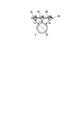
- the three hall sensors 3U, 3V, and 3W are attached to a planar substrate 3B that is separated from the sensor magnet 2, as shown in FIG.
- the distance Lv to the center line 2C in the rotation of the sensor magnet 2 of the hall sensor 3V (predetermined sensor) is the shortest distance among the distances Lu, Lv and Lw of the three hall sensors 3U, 3V and 3W.
- the Hall sensor 3V is a predetermined sensor that serves as a reference when calculating the V-phase correction angle described later, but other Hall sensors are attached to the planar substrate 3B at the shortest distance. In the case of being present, another Hall sensor attached to the planar substrate 3B at the shortest distance may be a predetermined sensor.
- the motor control device 4 is supplied with an inverter circuit 6 for switching currents to be passed from the DC power supply 5 to the coils U, V and W, three hall sensors 3U, 3V and 3W, and outputs of the hall sensors 3U, 3V and 3W. And a control circuit 7 for switching the inverter circuit 6.
- first arm 11, a second arm 12, and a third arm 13 are connected in parallel to the DC power supply 5.
- first arm 11 the connection point between the two switching elements WH and WL is connected to the coil W.
- second arm 12 the connection point between the two switching elements VH and VL is connected to the coil V.
- third arm 13 the connection point between the two switching elements UH and UL is connected to the coil U.
- the switching elements WH, WL, VH, VL, UH and UL are connected to an IGBT (insulated gate bipolar transistor), a cathode connected to the collector of the IGBT, and an anode connected to the emitter of the IGBT.
- IGBT insulated gate bipolar transistor
- the coils U, V, and W are star-connected. The ends of the coils U, V, and W opposite to the intersection (neutral point) side are electrically connected to the inverter circuit 6, respectively.
- MOSFET metal oxide semiconductor field effect transistor
- the hall sensors 3U, 3V and 3W included in the motor control device 4 are constituted by, for example, a hall IC (integrated circuit).
- the hall sensors 3U, 3V and 3W detect the rotational position of the rotary shaft, and the hall sensor 3U outputs a position detection signal Hu to the control circuit 7 as an output signal corresponding to the U phase.
- the Hall sensor 3V outputs a position detection signal Hv to the control circuit 7 as an output signal corresponding to the V phase
- the Hall sensor 3W outputs to the control circuit 7 as an output signal corresponding to the W phase.
- a position detection signal Hw is output.
- the control circuit 7 includes a gate control voltage output unit 8 and a control unit 9.
- the gate control voltage output unit 8 is based on the PWM signals (drive signals) CWH, CWL, CVH, CVL, CUH and CUL input from the drive signal generation unit 91, and the switching elements WH, WL, VH, VL, UH and UL.
- PWM signals GWH, GWL, GVH, GVL, GUH, and GUL applied to each gate are generated and output.
- the control unit 9 is a microcomputer (processor) provided with a CPU (Central Processing Unit), RAM (Random Access Memory), ROM (Read Only Memory) and the like.
- the ROM includes a rewritable nonvolatile storage device such as a flash memory.
- the control unit 9 includes a drive signal generation unit 91, a position correction unit 92, an output pattern selection unit 93, a correction information generation unit 94, and a storage unit 95.
- the storage unit 95 stores drive information 951, a correction coefficient 952, a V-phase correction angle 953, a first output pattern 954, and a second output pattern 955.
- the motor control device 4 of this embodiment has at least the following two functions. That is, the motor control device 4 generates and stores correction information for correcting detection errors of the position detection signals Hu, Hv and Hw of the hall sensors 3U, 3V and 3W, and the hall sensors 3U, 3V and Based on the 3W position detection signals Hu, Hv, and Hw and the stored correction information, the brushless motor 1 is driven and controlled (hereinafter referred to as a drive control function).
- the drive information 951 stored in the storage unit 95 is information representing how the control circuit 7 drives the inverter circuit 6 in the drive control function.
- the drive information 951 includes, for example, an operation command related to driving of the brushless motor 1 (representing command contents such as start, stop, normal rotation, reverse rotation, output, rotation speed, etc.), advance angle and energization in the energization control of the inverter circuit 6. It includes information representing the correspondence with the corner command value.
- the drive signal generation unit 91 determines the advance angle value and the energization angle value by referring to the drive information 951, for example.
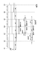
- FIG. 3 is an explanatory diagram for explaining an example of the position detection signals Hu, Hv, and Hw output from the hall sensors 3U, 3V, and 3W, and the advance angle and the energization angle in the energization control of the inverter circuit 6.
- FIG. 3 shows a correspondence relationship between the position detection signals Hu, Hv, and Hw and an angle region in which the switching element VH is turned on.
- the horizontal axis represents the rotational position of the magnetic pole of the rotor of the brushless motor 1 in electrical angle.
- the position detection signals Hu, Hv, and Hw have a phase difference of 120 ° from each other with an electrical angle of 360 ° as one cycle, and change to an H level or an L level every 180 °.
- the change from the L level to the H level of the position detection signal Hu is referred to as a hole edge HE1.
- the change from the H level to the L level of the position detection signal Hu is referred to as a hole edge HE4.
- the change from the L level to the H level of the position detection signal Hv is referred to as a hole edge HE3.
- a change from the H level to the L level of the position detection signal Hv is referred to as a hole edge HE6.
- the change from the L level to the H level of the position detection signal Hw is referred to as a hole edge HE5.
- the change from the H level to the L level of the position detection signal Hw is referred to as a hole edge HE2.
- the electrical angle between the hole edges is 60 °.
- the area between the hole edge HE1 and the hole edge HE2 is referred to as a hole stage 1 (hereinafter simply referred to as stage 1 (hereinafter the same)).
- stage 1 the area between the hole edge HE2 and the hole edge HE3
- stage 3 the hole edge HE4
- a stage 3 the hole edge HE3 and the hole edge HE4
- a portion between the hole edge HE4 and the hole edge HE5 is referred to as a stage 4.
- a portion between the hole edge HE5 and the hole edge HE6 is referred to as a stage 5.
- a portion between the hole edge HE6 and the hole edge HE1 is referred to as a stage 6.
- the drive signal generation unit 91 turns on the switching element VH in synchronization with the hall edge HE3 and synchronizes with the hall edge HE5. Turn off.
- the hall sensors 3U, 3V and 3W generate the hall edges HE1 to HE6 at positions where the position detection signals Hu, Hv and Hw are advanced by 30 ° in electrical angle with respect to the magnetic pole position of the rotor. Has been placed. Therefore, when the switching element VH is turned on in synchronization with the hole edge HE3, the advance value becomes 30 °.
- the drive signal generation unit 91 changes the values of the advance angle and the energization angle based on the energization control with the advance angle of 30 ° and the energization angle of 120 °.
- the drive signal generation unit 91 retards the switching element VH by 10 ° from the hall edge HE3 and 5 °.
- the advanced rotation position rotates on at the advanced rotation position (rotation position delayed by 5 ° from the hole edge HE3).
- the drive signal generator 91 is turned off at a rotational position where the switching element VH is retarded by 15 ° from the hole edge HE5.
- the drive signal generation unit 91 advances the switching element VH by 30 ° from the hall edge HE 3 and further 22 Turned on at a rotational position advanced by 5 ° (rotational position advanced by 52.5 ° from the hole edge HE3).
- the correction coefficient 952 and the V-phase correction angle 953 stored in the storage unit 95 are information for correcting detection errors included in the position detection signals Hu, Hv, and Hw output from the hall sensors 3U, 3V, and 3W. It is generated by the correction information generation unit 94.
- the correction information generation unit 94 generates a correction coefficient 952 and a V-phase correction angle 953 based on the position detection signals Hu, Hv, and Hw output from the hall sensors 3U, 3V, and 3W.
- the correction coefficient 952 is a coefficient for correcting the variation when there is a variation in the interval between the hole edges HE1 to HE6 in the position detection signals Hu, Hv, and Hw.
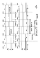
- 4 shows the position detection signals Hu, Hv, and Hw, and the position detection signals Huc, Hvc, and Hwc obtained by correcting the position detection signals Hu, Hv, and Hw by the position correction unit 92.
- 3 is a diagram illustrating an example of energization control in the same manner as FIG.
- the correction information generation unit 94 measures the time intervals T1 to T6 of the hole edges HE1 to HE6 in the position detection signals Hu, Hv and Hw with the brushless motor 1 rotated at a constant speed. Then, the correction information generation unit 94 determines, as a reference hole edge, a hole edge whose time interval is reduced by widening the position of the hole edge in the rotation direction of the brushless motor 1 out of the two hole edges having the minimum time interval. Any one of the position detection signals Hu, Hv and Hw corresponding to the phase with the reference hole edge is determined as the reference position detection signal. In the example shown in FIG.
- the time interval T4 is the smallest, and the hole edge HE4 and the hole edge HE5 that have a time interval that becomes smaller by moving the position of the hole edge in the rotation direction is the hole edge HE4. is there. Therefore, the hole edge HE4 becomes the reference hole edge, and the position detection signal Hu becomes the reference position detection signal.
- the correction information generation unit 94 calculates an average value of time intervals corresponding to the H level or L level of the determined reference position detection signal.
- the correction information generation unit 94 calculates an average value of the time intervals T1, T2, and T3 corresponding to the H level of the position detection signal Hu determined as the reference position detection signal, and supports the L level.
- the average value of the time intervals T4, T5 and T6 to be calculated is calculated.
- the correction information generation unit 94 calculates the ratio between the calculated average value and each time interval as a correction coefficient for each of the hole edges HE1 to HE6.
- the correction information generation unit 94 stores the calculated correction coefficient for each of the hole edges HE1 to HE6 in the storage unit 95 as the correction coefficient 952 together with information for specifying the reference position detection signal.
- the position correction unit 92 uses the correction coefficient 952 generated by the correction information generation unit 94 to correct the intervals between the hole edges HE1 to HE6 in the position detection signals Hu, Hv, and Hw, thereby correcting the position detection signal.
- Huc, Hvc, and Hwc are generated and output to the drive signal generation unit 91.
- the position correction unit 92 corrects the positions of the hole edges HE1 to HE6 in the position detection signals Hu, Hv, and Hw using the correction coefficient 952, and sets the equally spaced hole edges HE1c to HE6c.
- the position detection signals Huc, Hvc and Hwc having the same are generated.
- the V-phase correction angle 953 is a V-phase hall sensor 3V when the correction coefficient 952 is calculated when the hall sensor 3V is used as a positioning reference with respect to the sensor magnet 2 in the structure shown in FIG. This is information for correcting the reference for energization control when the position detection signal is other than the position detection signal Hv. Specifically, in the example shown in FIG. 4, the difference between the hole edges HE3 and HE6 in the position detection signal Hv and the hole edges HE3c and HE6c in the corrected position detection signal Hvc is expressed as an electrical angle. The V-phase correction angle 953 is obtained.
- V-phase correction angle 953 When the potential angle of the difference between the hole edge HE3 and the hole edge HE3c is different from the potential angle of the difference between the hole edge HE6 and the hole edge HE6c, for example, an average value of these potential angles is set as a V-phase correction angle 953. be able to.
- the correction information generation unit 94 calculates the time interval between the hole edges HE1 to HE6 in the position detection signals Hu, Hv, and Hw measured with the brushless motor 1 rotated at a constant speed in the same manner as when calculating the correction coefficient 952.
- the V-phase correction angle 953 can be determined using T1 to T6.
- the correction information generation unit 94 stores the determined V-phase correction angle 953 in the storage unit 95. This V-phase correction angle 953 is used in energization control by the drive signal generation unit 91.
- the drive signal generation unit 91 executes energization control based on the corrected position detection signals Huc, Hvc, and Hwc generated by the position correction unit 92. At that time, the drive signal generation unit 91 increases the advance value by the angle of the V-phase correction angle 953. Accordingly, the drive signal generation unit 91 can perform energization control on the basis of the hole edges HE3 and HE6 of the position detection signal Hv before correction in a pseudo manner. For example, in the example illustrated in FIG. 4, when performing energization control with an advance angle of 30 ° and an energization angle of 120 °, the drive signal generation unit 91 sets the advance angle to (the value of the V-phase correction angle 953 + 30 °). .
- the drive signal generator 91 is turned on at a position where the switching element VH is advanced by the value of the V-phase correction angle 953 from the hall edge HE3c, and the switching element VH is advanced by the value of the V-phase correction angle 953 from the hall edge HE5c. Turn off at the position where it was moved.
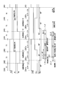
- FIG. 5 shows the position detection signals Hu, Hv, and Hw corrected by the position correction unit 92 with the position detection signals Hu, Hv, and Hw, and the position detection signals Hu, Hv, and Hw as shown in FIG. It is a figure which shows an example of electricity supply control similarly to FIG.
- the example of energization control shown in FIG. 5 is a case where the advance angle is 60 ° and the energization angle is 165 °. If the advance angle corresponding to the V-phase correction angle 953 is not performed, the period during which the switching element VH is turned on is within the corrected stages 2 to 4 from the hole edges HE2c to HE5c. In this case, the switching element VH is turned on at a position delayed by 7.5 ° from the position of the hole edge HE2c, and the switching element VH is turned off at a position advanced by 7.5 ° from the position of the hole edge HE5c.
- the energization control in which the advance angle shown in FIG. 5 is set to the V-phase correction angle + 60 ° is more than the energization control of the advance angle 60 ° and the energization angle 165 ° that does not have the advance of the V-phase correction angle 953. Theoretically, the error should be small.
- an output pattern (second output pattern 955) corresponding to the excess angle (within the maximum V-phase correction angle) is prepared.
- the output pattern includes a plurality of energization patterns.
- the energization pattern is a combination of operation states of the plurality of switching elements WH, WL, VH, VL, UH, and UL.
- FIG. 6 is a diagram for explaining an example of the first output pattern 954.
- FIG. 6 is a diagram illustrating a correspondence relationship between the corrected position detection signals Huc, Hvc, and Hwc and the energization patterns of the respective switching elements UH, UL, VH, VL, WH, and WL, where the horizontal axis is an electrical angle. .
- the switching elements UH, UL, VH, VL, WH and WL are continuously turned on (“ON”) or continuously turned off (“OFF”) (“ON” or “PWM”).
- OFF continuously turned off
- PWM controlled state PWM
- Each stage 1 to 6 is further divided into three sections A, B and C, respectively. For the sections A, B and C, energization patterns are individually set. The periods (electrical angles) of the sections A, B and C vary depending on the advance value (including the V-phase correction angle) and the energization angle value.
- the energization pattern of the section A indicates that the switching elements UH, UL, VH, VL, WH and WL are “OFF”, “OFF”, “PWM”, respectively. , “PWM”, “ON”, and “OFF”.
- the energization pattern of the section B indicates that the switching elements UH, UL, VH, VL, WH and WL are combinations of “PWM”, “PWM”, “PWM”, “ON”, and “OFF”, respectively. It is.
- the energization pattern of section C indicates that the switching elements UH, UL, VH, VL, WH and WL are combinations of “PWM”, “PWM”, “OFF”, “OFF”, “ON”, and “OFF”, respectively. It is.
- FIG. 7 summarizes the example of the first output pattern 954 shown in FIG. 6 as a table.
- the storage unit 95 stores the first output pattern 954 in a format as shown in FIG. 7, for example.
- “1” indicates ON
- “0” indicates OFF
- “P” indicates PWM.
- FIG. 8 is a diagram for explaining an example of the second output pattern 955.
- FIG. 8 shows the correspondence between the corrected position detection signals Huc, Hvc, and Hwc and the energization patterns of the switching elements UH, UL, VH, VL, WH, and WL, with the horizontal axis representing the electrical angle as in FIG. It is a figure which shows a relationship.
- each of the stages 1 to 6 is further divided into three sections A, B, and C, respectively.
- the periods (electrical angles) of the sections A, B and C vary depending on the advance value (including the V-phase correction angle) and the energization angle value.
- the section C corresponds to the excess angle described with reference to FIG.
- the electrical angle of the section C is set to (V phase correction angle + advanced angle (angle reduced by electrical angle 30 °) + energization angle (1/2 of the angle increased from 120 °)). Further, the electrical angle in the section C is limited to the value of the V-phase correction angle at the maximum.
- the energization pattern of the section A is that the switching elements UH, UL, VH, VL, WH and WL are “PWM”, “PWM”, “PWM”, respectively. , “PWM”, “ON”, and “OFF”.
- the energization pattern of the section B is a combination of the switching elements UH, UL, VH, VL, WH and WL of “PWM”, “PWM”, “OFF”, “OFF”, “ON” and “OFF”, respectively. It is.
- the energization pattern of section C indicates that the switching elements UH, UL, VH, VL, WH and WL are combinations of “PWM”, “PWM”, “ON”, “OFF”, “ON”, and “OFF”, respectively. It is.
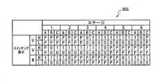
- FIG. 9 summarizes the example of the second output pattern 955 shown in FIG. 8 as a table.
- the storage unit 95 stores the second output pattern 955 in a format as shown in FIG. In FIG. 9, “1” is on, “0” is off, and “P” is PWM.
- the output pattern selection unit 93 refers to the V phase correction angle 953 stored in the storage unit 95 and receives the set values of the advance angle and the energization angle in the energization control from the drive signal generation unit 91. And the output pattern selection part 93 selects an output pattern by the process shown in FIG. 10, for example, and transmits the information which shows the selected output pattern to the drive signal generation part 91.
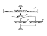
- FIG. 10 is a flowchart showing an operation example of the output pattern selection unit 93.
- the output pattern selection unit 93 performs the process shown in FIG. 10 when, for example, the setting value of the advance angle or the conduction angle is changed in the drive signal generation unit 91.
- the output pattern selection unit 93 calculates a value of V-phase correction angle + advanced angle (angle reduced by 30 ° electrical angle) + energization angle (1 ⁇ 2 of the angle increased from 120 °) (step S1).
- the output pattern selection unit 93 determines whether or not the value calculated in step S1 is larger than 60 ° (step S2). When the calculated value is not larger than 60 ° (No in Step S2), the output pattern selection unit 93 selects the first output pattern 954 (Step S3).
- Step S4 the output pattern selection unit 93 selects the second output pattern 955 (Step S4). After the processes in steps S1 to S4, the output pattern selection unit 93 transmits information indicating the selected output pattern to the drive signal generation unit 91, and ends the process.
- the motor control device 4 of the present embodiment corrects variations in the position detection signals Hu, Hv, and Hw output from the hall sensors 3U, 3V, and 3W, and corrects the position detection signal Hvc in the hall.
- the advance angle of the V-phase correction angle corresponding to the position difference between the edges H3c and H6c and the hall edge H3 and H6 of the position detection signal Hv of the hall sensor 3V is corrected. Therefore, the detection error of the rotational position of the rotor can be accurately corrected at a low cost.
- the motor control device 4 of the present embodiment controls the energization control by selectively using two types of output patterns in the energization control and adding the V-phase correction angle to the set value of the advance angle.
- the range (advance angle range and energization angle range) is not limited.
- the present embodiment is a motor control device 4 that performs energization control on the three-phase coils U, V, and W of the brushless motor 1 to control rotation of the rotor.
- the motor control device 4 includes a plurality of switching elements UH, UL, VH, VL, WH, and WL arranged so as to be able to switch currents flowing through the coils U, V, and W; and a plurality of holes that detect the rotational position of the rotor.
- Sensors 3U, 3V, and 3W based on position detection signals Huc, Hvc, and Hwc obtained by correcting the position detection signals Hu, Hv, and Hw, which are outputs of the plurality of hall sensors 3U, 3V, and 3W, using a predetermined correction coefficient
- a control unit 9 that outputs PWM signals (drive signals) CWH, CWL, CVH, CVL, CUH, and CUL for controlling energization patterns of the switching elements UH, UL, VH, VL, WH, and WL.
- the control unit 9 determines the difference between before and after correction of the position detection signals Hv and Hvc of the hall sensor 3V (predetermined sensor) among the hall sensors 3U, 3V and 3W with respect to the set value of the advance angle of the energization control.
- a corresponding V-phase correction angle (correction angle) is added, and an output pattern that is used when selecting an energization pattern including a plurality of energization patterns is determined from a different first output pattern and second output pattern. The selection is made according to the added advance angle and the energization angle of energization control.
- the energization pattern is controlled in synchronization with the rising or falling timing (hall edge) of the position detection signals Huc, Hvc, and Hwc, and the first output pattern includes switching elements over three or more timings.
- the second output pattern is an output pattern including an energization pattern in which the switching element is continuously in the same energization state over three or more timings. is there.
- the motor control device 4 in the above-described embodiment may be realized by a computer.
- a program for realizing this function may be recorded on a computer-readable recording medium, and the program recorded on this recording medium may be read into a computer system and executed.
- the “computer system” includes an OS and hardware such as peripheral devices.
- the “computer-readable recording medium” refers to a storage device such as a flexible medium, a magneto-optical disk, a portable medium such as a ROM or a CD-ROM, and a hard disk incorporated in a computer system.
- the “computer-readable recording medium” dynamically holds a program for a short time like a communication line when transmitting a program via a network such as the Internet or a communication line such as a telephone line.
- a volatile memory inside a computer system serving as a server or a client in that case may be included and a program held for a certain period of time.
- the program may be a program for realizing a part of the above-described functions, and may be a program capable of realizing the functions described above in combination with a program already recorded in a computer system. It may be realized using a programmable logic device such as an FPGA (Field Programmable Gate Array).
- FPGA Field Programmable Gate Array
Landscapes
- Engineering & Computer Science (AREA)
- Power Engineering (AREA)
- Control Of Motors That Do Not Use Commutators (AREA)
Abstract
ブラシレスモータの3相のコイルに通電制御を行って、ロータの回転制御を行うモータ制御装置は、コイルに流す電流を切り替え可能に配置された複数のスイッチング素子と;ロータの回転位置を検出する複数のセンサと;複数のセンサの出力である位置検出信号を所定の補正係数を用いて補正した位置検出信号に基づいて各スイッチング素子の通電パターンを制御するための駆動信号を出力する制御部と;を備え、制御部は、通電制御の進角の設定値に対して、複数のセンサのうち所定のセンサの位置検出信号の補正前後の差分に対応する補正角を付加し、複数の通電パターンを含み通電パターンを選択する際に用いられる出力パターンを、異なる複数の出力パターンから、補正角を付加した進角と通電制御の通電角とに応じて選択する。
Description
本発明は、モータ制御装置およびモータ制御装置の制御方法に関する。
本願は、2017年2月15日に出願された日本国特許出願2017-025961号に基づき優先権を主張し、その内容をここに援用する。
本願は、2017年2月15日に出願された日本国特許出願2017-025961号に基づき優先権を主張し、その内容をここに援用する。
ブラシレスモータは、3相のコイルU、VおよびWを有するステータと、界磁用の永久磁石を有するロータとを備える。ブラシレスモータは、ロータの回転位置に応じてステータの通電制御を行うことで駆動される。ロータの回転位置は、例えば、ロータが有する磁極の位置あるいはロータと共に回転するセンサマグネットの磁極の位置を複数のホールセンサ等を用いて検出することで、取得されている。ロータの回転位置の検出においては、ホールセンサの配置のばらつきや、ホールセンサが対向する磁極のバラツキ等によって検出誤差が発生する(例えば、特許文献1~3)。特許文献1~3には、ロータの回転位置の検出誤差を補正するための構成が示されている。
特許文献1に記載されている構成では、予め計測した各ホールセンサの正規位置からの位置ずれを記憶しておき、記憶した情報に基づき回転位置の検出誤差が補正される。この場合に、位置ずれの計測は、ロータの角度を例えば0.1°刻みで回転させながらホールセンサの出力を確認することで行われる。また、特許文献2に記載されている構成では、センサマグネットが1回転する周期を計測し、計測した1回転分の周期を磁極数で除することで各磁極間の理想周期が算出される。そして、算出した理想周期を用いて各センサにおける検出誤差が算出される。また、特許文献3が記載されている構成では、ロータを所定回転数で回転させ、誤差がない場合の理論値と、実際の計測結果とを比較することで検出誤差が算出される。
特許文献1に記載されている構成では、ロータの回転位置をホールセンサとは別の計測機器を用いて計測しながら各ホールセンサの出力を確認することで位置ずれが計測される。この構成では、ロータの所定位置を基準として、ホールセンサの位置ずれや磁極位置のずれを取得することができる。この場合、所定位置を基準としてホールセンサ毎に検出位置を補正することができる。しかしながら、位置ずれの計測にコストがかかってしまうという課題がある。
一方、特許文献2および特許文献3に記載されている構成では、ホールセンサ間や磁極間の間隔のばらつきを補正することはできる。しかしながら、複数のホールセンサの検出位置のうち、どのホールセンサの検出位置が理論値に最も近いのかということまでは把握することができない。
本発明の態様は、ロータの回転位置の検出誤差を低コストで精度良く補正することができるモータ制御装置およびモータ制御装置の制御方法を提供することを目的とする。
本発明の一態様は、ブラシレスモータの3相のコイルに通電制御を行って、ロータの回転制御を行うモータ制御装置であって、前記コイルに流す電流を切り替え可能に配置された複数のスイッチング素子と;前記ロータの回転位置を検出する複数のセンサと;前記複数のセンサの出力である位置検出信号を所定の補正係数を用いて補正した位置検出信号に基づいて各スイッチング素子の通電パターンを制御するための駆動信号を出力する制御部と;を備え、前記制御部は、前記通電制御の進角の設定値に対して、前記複数のセンサのうち所定のセンサの前記位置検出信号の補正前後の差分に対応する補正角を付加し、複数の前記通電パターンを含み前記通電パターンを選択する際に用いられる出力パターンを、異なる複数の前記出力パターンから、前記補正角を付加した前記進角と前記通電制御の通電角とに応じて選択する。
上記モータ制御装置では、前記通電パターンは、前記位置検出信号の立ち上がりまたは立ち下がりのタイミングに同期して制御され、前記複数の出力パターンは、3以上の前記タイミングにわたって前記スイッチング素子を継続的に同一の通電状態とする通電パターンを含まない第1出力パターンと、3以上の前記タイミングにわたって前記スイッチング素子を継続的に同一の通電状態とする通電パターンを含む第2出力パターンと、を含んでもよい。
また、本発明の別の一態様に係るモータ制御装置の制御方法は、ブラシレスモータの3相のコイルに通電制御を行って、ロータの回転制御を行うモータ制御装置の制御方法であって、前記モータ制御装置は、前記コイルに流す電流を切り替え可能に配置された複数のスイッチング素子と;前記ロータの回転位置を検出する複数のセンサと;前記複数のセンサの出力である位置検出信号を所定の補正係数を用いて補正した位置検出信号に基づいて各スイッチング素子の通電パターンを制御するための駆動信号を出力する制御部と;を備え、前記制御方法は、前記制御部によって、前記通電制御の進角の設定値に対して、前記複数のセンサのうち所定のセンサの前記位置検出信号の補正前後の差分に対応する補正角を付加することと;複数の前記通電パターンを含み前記通電パターンを選択する際に用いられる出力パターンを、異なる複数の前記出力パターンから、前記補正角を付加した前記進角と前記通電制御の通電角とに応じて選択することと;を含む。
本発明の態様によれば、ロータの回転位置の検出誤差を低コストで精度良く補正することができる。
以下、実施形態を通じて本発明を説明するが、本発明は以下の実施形態に限定されない。また、実施形態の中で説明されている特徴の組み合わせの全てが発明の解決手段に必須であるとは限らない。なお、図面において、同一又は類似の部分には同一の符号を付して、重複する説明を省く場合がある。また、図面における要素の形状および大きさなどはより明確な説明のために誇張されることがある。
以下、本実施形態におけるモータ制御装置を、図面を用いて説明する。
図1は、本実施形態のモータ制御装置4の制御系統を示すブロック図である。図1は、ブラシレスモータ1およびモータ制御装置4の構成を示している。ブラシレスモータ1は、3相のコイルU、VおよびWを有するステータと、界磁用の永久磁石を有するロータとを備える。ロータの回転軸には、ロータと共に回転するセンサマグネット2が取り付けられている。
センサマグネット2は、回転方向にS極とN極が交互に着磁されている。センサマグネット2の近傍には、回転位置を検出する3つのホールセンサ3U、3Vおよび3W(センサ)が回転方向に120°の間隔で、センサマグネット2の磁極の切り替わりを検出できるように取り付けられている。3つのホールセンサ3U、3Vおよび3Wは、図2に示すように、センサマグネット2から離間された平面的な基板3Bに取り付けられている。ホールセンサ3V(所定のセンサ)のセンサマグネット2の回転における中心線2Cに対する距離Lvは、3つのホールセンサ3U、3Vおよび3Wの距離Lu、LvおよびLwのうち最短な距離である。このような構造では、センサマグネット2に対して3つのホールセンサ3U、3Vおよび3Wのうち中心に位置し、かつ最短距離に位置するホールセンサ3Vを基準としてセンサマグネット2に対する位置決めを行うことが適切である。例えば、ホールセンサ3Uを基準とした場合、ホールセンサ3Wの検出誤差が、ホールセンサ3Vを基準とする場合と比較して大きくなりやすくなる。なお、本実施形態において、ホールセンサ3Vが後述するV相補正角を算出する際に基準となる所定のセンサであるが、他のホールセンサが最短な距離で平面的な基板3Bに取り付けられている場合、最短な距離で平面的な基板3Bに取り付けられている他のホールセンサが所定のセンサであってもよい。
モータ制御装置4は、直流電源5からコイルU、VおよびWに流す電流を切り換えるインバータ回路6と、3つのホールセンサ3U、3Vおよび3Wと、各ホールセンサ3U、3Vおよび3Wの出力が入力され、インバータ回路6のスイッチングを行う制御回路7とを有する。
インバータ回路6は、3つのアーム(第1のアーム11、第2のアーム12および第3のアーム13)が直流電源5に対して並列に接続されている。第1のアーム11は、2つのスイッチング素子WHおよびWLの接続点がコイルWに接続されている。第2のアーム12は、2つのスイッチング素子VHおよびVLの接続点がコイルVに接続されている。第3のアーム13は、2つのスイッチング素子UHおよびULの接続点がコイルUに接続されている。なお、図1に示す例では、スイッチング素子WH、WL、VH、VL、UHおよびULを、IGBT(絶縁ゲートバイポーラトランジスタ)と、IGBTのコレクタに接続されたカソード及びIGBTのエミッタに接続されたアノードを有する環流ダイオードとから構成しているが、例えばMOSFET(金属酸化膜半導体電界効果トランジスタ)等から構成してもよい。コイルU、VおよびWは、例えば、スター結線されている。交点(中性点)側と反対側のコイルU、VおよびWの端部は、インバータ回路6にそれぞれ電気的に接続されている。
モータ制御装置4が有するホールセンサ3U、3Vおよび3Wは、例えば、ホールIC(集積回路)で構成される。ロータの回転軸が回転するとホールセンサ3U、3Vおよび3Wは回転軸の回転位置を検出し、ホールセンサ3Uは、U相に対応する出力信号として、制御回路7に対して位置検出信号Huを出力し、ホールセンサ3Vは、V相に対応する出力信号として、制御回路7に対して位置検出信号Hvを出力し、ホールセンサ3Wは、W相に対応する出力信号として、制御回路7に対して位置検出信号Hwを出力する。
制御回路7は、ゲート制御電圧出力部8と、制御部9とを含む。
ゲート制御電圧出力部8は、駆動信号生成部91から入力したPWM信号(駆動信号)CWH、CWL、CVH、CVL、CUHおよびCULに基づき、スイッチング素子WH、WL、VH、VL、UHおよびULの各ゲートに印加されるPWM信号GWH、GWL、GVH、GVL、GUHおよびGULを生成して出力する。
制御部9は、CPU(中央処理装置)、RAM(ランダムアクセスメモリ)、ROM(リードオンリメモリ)等を備えたマイクロコンピュータ(プロセッサ)である。ここで、ROMは、フラッシュメモリ等の書き換え可能な不揮発性記憶装置を含む。制御部9は、駆動信号生成部91と、位置補正部92と、出力パターン選択部93と、補正情報生成部94と、記憶部95を有する。記憶部95は、駆動情報951、補正係数952、V相補正角953、第1出力パターン954および第2出力パターン955を記憶する。
本実施形態のモータ制御装置4は、少なくとも次の2つの機能を有する。すなわち、モータ制御装置4は、ホールセンサ3U、3Vおよび3Wの位置検出信号Hu、HvおよびHwが有する検出誤差を補正するための補正情報を生成して記憶する機能と、ホールセンサ3U、3Vおよび3Wの位置検出信号Hu、HvおよびHwと記憶した補正情報とに基づき、ブラシレスモータ1を駆動制御する機能(以下、駆動制御機能という)とを有する。
記憶部95が記憶する駆動情報951は、駆動制御機能において、制御回路7がインバータ回路6をどのように駆動するかを表す情報である。駆動情報951は、例えば、ブラシレスモータ1の駆動に係る動作指令(始動、停止、正転、逆転、出力、回転数等の指令内容を表す)と、インバータ回路6の通電制御における進角および通電角の指令値との対応関係を表す情報を含む。駆動信号生成部91は、例えば、駆動情報951を参照する等して、進角の値や通電角の値を決定する。
図3は、ホールセンサ3U、3Vおよび3Wが出力した位置検出信号Hu、HvおよびHwと、インバータ回路6の通電制御における進角および通電角の一例を説明するための説明図である。図3は、位置検出信号Hu、HvおよびHwとスイッチング素子VHがオンされる角度領域との対応関係を示す。横軸は、ブラシレスモータ1のロータの磁極の回転位置を電気角で表す。位置検出信号Hu、HvおよびHwは、電気角360°を1周期として、互いに120°の位相差を有し、180°毎にHレベルまたはLレベルに変化する。本実施形態では、位置検出信号HuのLレベルからHレベルへの変化をホールエッジHE1と称する。位置検出信号HuのHレベルからLレベルへの変化をホールエッジHE4と称する。位置検出信号HvのLレベルからHレベルへの変化をホールエッジHE3と称する。位置検出信号HvのHレベルからLレベルへの変化をホールエッジHE6と称する。位置検出信号HwのLレベルからHレベルへの変化をホールエッジHE5と称する。位置検出信号HwのHレベルからLレベルへの変化をホールエッジHE2と称する。ホールセンサ3U、3Vおよび3Wが出力した位置検出信号Hu、HvおよびHwが誤差を含んでいないとすると(図3に示す例は位置検出信号Hu、HvおよびHwが誤差を含んでいない場合である)、各ホールエッジ間の電気角は60°である。また、ホールエッジHE1とホールエッジHE2の間をホールステージ1(以下、単にステージ1という(以下、同様))と称する。ホールエッジHE2とホールエッジHE3の間をステージ2と称する。ホールエッジHE3とホールエッジHE4の間をステージ3と称する。ホールエッジHE4とホールエッジHE5の間をステージ4と称する。ホールエッジHE5とホールエッジHE6の間をステージ5と称する。ホールエッジHE6とホールエッジHE1の間をステージ6と称する。
インバータ回路6の通電制御において進角を30°とし、通電角を120°とする場合、駆動信号生成部91は、スイッチング素子VHをホールエッジHE3に同期してオンし、ホールエッジHE5に同期してオフする。本実施形態において、ホールセンサ3U、3Vおよび3Wは、位置検出信号Hu、HvおよびHwがロータの磁極位置に対して電気角で30°進角した位置でホールエッジHE1~HE6を発生するように配置されている。
したがって、スイッチング素子VHをホールエッジHE3に同期してオンすることで、進角の値は30°となる。本実施形態において、駆動信号生成部91は、この進角30°および通電角を120°の通電制御を基準として、進角と通電角の値を変化させる。
したがって、スイッチング素子VHをホールエッジHE3に同期してオンすることで、進角の値は30°となる。本実施形態において、駆動信号生成部91は、この進角30°および通電角を120°の通電制御を基準として、進角と通電角の値を変化させる。
また、例えば、インバータ回路6の通電制御において進角を20°とし、通電角を130°とする場合、駆動信号生成部91は、スイッチング素子VHをホールエッジHE3から10°遅角させかつ5°進角させた回転位置(ホールエッジHE3から5°遅角させた回転位置)でオンする。ここで、10°の遅角分は、進角を20°とする場合に基準となる進角30°からの変化分(20°-30°=-10°)に対応する。また、5°の進角分は、基準となる通電角120°からの通電角130°の変化分の2分の1((130°-120°)×0.5=5°)に対応する。また、駆動信号生成部91は、スイッチング素子VHをホールエッジHE5から15°遅角させた回転位置でオフする。
また、例えば、インバータ回路6の通電制御において進角を60°とし、通電角を165°とする場合、駆動信号生成部91は、スイッチング素子VHをホールエッジHE3から30°進角させ且つさらに22.5°進角させた回転位置(ホールエッジHE3から52.5°進角させた回転位置)でオンする。ここで、30°の進角分は、進角を60°とする場合に基準となる進角30°からの変化分(60°-30°=30°)に対応する。また、22.5°の進角分は、基準となる通電角120°からの通電角165°の変化分の2分の1((165°-120°)×0.5=22.5°)に対応する。また、駆動信号生成部91は、スイッチング素子VHをホールエッジHE5から7.5°進角させた回転位置でオフする。
一方、記憶部95が記憶する補正係数952とV相補正角953は、ホールセンサ3U、3Vおよび3Wが出力する位置検出信号Hu、HvおよびHwが含む検出誤差を補正するための情報であり、補正情報生成部94によって生成される。補正情報生成部94は、ホールセンサ3U、3Vおよび3Wが出力した位置検出信号Hu、HvおよびHwに基づいて、補正係数952とV相補正角953を生成する。
まず、補正係数952について説明する。補正係数952は、例えば図4に示すように、位置検出信号Hu、HvおよびHwにおけるホールエッジHE1~HE6の間隔にばらつきがある場合に、ばらつきを補正するための係数である。なお、図4は、横軸を電気角とし、位置検出信号Hu、HvおよびHwと、位置検出信号Hu、HvおよびHwを位置補正部92で補正した位置検出信号Huc、HvcおよびHwcと、図3と同様にして通電制御の一例を示す図である。
補正情報生成部94は、ブラシレスモータ1を一定速度で回転させた状態で、位置検出信号Hu、HvおよびHwにおけるホールエッジHE1~HE6の時間間隔T1~T6を計測する。そして、補正情報生成部94は、時間間隔が最小の2つのホールエッジのうち、ブラシレスモータ1の回転方向にホールエッジの位置を広げることで時間間隔が小さくなるホールエッジを基準ホールエッジと決定し、基準ホールエッジがある相に対応する位置検出信号Hu、HvおよびHwのいずれか1つを基準位置検出信号と決定する。図4に示す例では、時間間隔T4が最小であり、ホールエッジHE4とホールエッジHE5のうち、回転方向にホールエッジの位置を移動させることで時間間隔が小さくなるホールエッジは、ホールエッジHE4である。したがって、ホールエッジHE4が基準ホールエッジとなり、位置検出信号Huが基準位置検出信号となる。
そして、補正情報生成部94は、決定した基準位置検出信号のHレベルまたはLレベルに対応する時間間隔の平均値を算出する。図4に示す例では、補正情報生成部94は、基準位置検出信号に決定した位置検出信号HuのHレベルに対応する時間間隔T1、T2およびT3の平均値を算出するとともに、Lレベルに対応する時間間隔T4、T5およびT6の平均値を算出する。さらに、補正情報生成部94は、算出した平均値と各時間間隔との比の値を補正係数としてホールエッジHE1~HE6毎に算出する。補正情報生成部94は、算出したホールエッジHE1~HE6毎の補正係数を、基準位置検出信号を特定する情報とともに、補正係数952として記憶部95に記憶する。
これに対し、位置補正部92は、補正情報生成部94が生成した補正係数952を用いて、位置検出信号Hu、HvおよびHwにおけるホールエッジHE1~HE6の間隔を補正し、補正した位置検出信号Huc、HvcおよびHwcを生成して駆動信号生成部91に対して出力する。図4に示す例では、位置補正部92は、補正係数952を用いて、位置検出信号Hu、HvおよびHwにおけるホールエッジHE1~HE6の各位置を補正し、等間隔のホールエッジHE1c~HE6cを有する位置検出信号Huc、HvcおよびHwcを生成する。
次に、V相補正角953について説明する。V相補正角953は、図2に示すような構造においてホールセンサ3Vをセンサマグネット2に対する位置決めの基準としている場合に、補正係数952を算出する際の基準位置検出信号がV相のホールセンサ3Vの位置検出信号Hv以外であったときに、通電制御の基準を補正するための情報である。具体的には、図4に示す例において、位置検出信号HvにおけるホールエッジHE3およびHE6と、補正後の位置検出信号HvcにおけるホールエッジHE3cおよびHE6cとの差を、電気角で表した値が、V相補正角953となる。ホールエッジHE3とホールエッジHE3cとの差の電位角とホールエッジHE6とホールエッジHE6cとの差の電位角とが異なる場合には、例えば、それら電位角の平均値をV相補正角953とすることができる。補正情報生成部94は、補正係数952を算出する際と同様に、ブラシレスモータ1を一定速度で回転させた状態で計測された位置検出信号Hu、HvおよびHwにおけるホールエッジHE1~HE6の時間間隔T1~T6を用いて、V相補正角953を決定することができる。補正情報生成部94は、決定したV相補正角953を記憶部95に記憶する。このV相補正角953は、駆動信号生成部91による通電制御において使用される。
駆動信号生成部91は、位置補正部92が生成した補正後の位置検出信号Huc、HvcおよびHwcに基づいて通電制御を実行する。その際、駆動信号生成部91は、V相補正角953の角度だけ、進角の値を増加させる。これによって、駆動信号生成部91は、擬似的に補正前の位置検出信号HvのホールエッジHE3およびHE6を基準として通電制御を行うことができる。例えば、図4に示す例では、進角30°で通電角120°の通電制御を行う場合に、駆動信号生成部91は、進角を(V相補正角953の値+30°)に設定する。駆動信号生成部91は、スイッチング素子VHをホールエッジHE3cよりV相補正角953の値だけ進角させた位置でオンし、スイッチング素子VHをホールエッジHE5cよりV相補正角953の値だけ進角させた位置でオフする。
しかしながら、駆動信号生成部91による通電制御において、V相補正角953の値だけ進角の値を大きくする場合、次のような課題が生じる。すなわち、図5に示すように、通電角や進角の値が比較的大きい場合、V相補正角953を付加しないときには越えることがなかった他のホールステージに通電期間がわたってしまうことがあるという課題が生じる。図5は、横軸を電気角とし、位置検出信号Hu、HvおよびHwと、位置検出信号Hu、HvおよびHwを位置補正部92で補正した位置検出信号Huc、HvcおよびHwcと、図3および図4と同様にして通電制御の一例を示す図である。
図5に示す通電制御の例は、進角60°で通電角165°とする場合である。仮にV相補正角953に対応する進角を行わなかったとすると、スイッチング素子VHをオンさせる期間は、補正後のホールエッジHE2c~HE5cまでのステージ2~4に収まっている。この場合、ホールエッジHE2cの位置から7.5°遅れた位置でスイッチング素子VHがオンしホールエッジHE5cの位置から7.5°進んだ位置でスイッチング素子VHがオフする。これに対し、V相補正角953の値が7.5°を越えた場合、7.5°を越えた超過角の分だけ、ステージ1に通電期間がわたってしまっている。V相補正角953による進角の付加分は、本来、検出誤差を補正するために設定されたものである。
よって、図5に示す進角をV相補正角+60°に設定する通電制御は、V相補正角953による進角の付加分を持たない進角60°、通電角165°の通電制御よりも理論的には誤差が小さいはずである。しかしながら、通常、越えることがなかったホールステージに、他のホールステージに設定されている通電期間がわたることになると、ホールステージを単位として設定されている通常の通電パターンでは対応することができなくなる。V相補正角を付加する前には問題なく実行することができた進角60°、通電角165°の通電制御が、V相補正角を付加することで実行できなくなるという課題が生じる。
よって、図5に示す進角をV相補正角+60°に設定する通電制御は、V相補正角953による進角の付加分を持たない進角60°、通電角165°の通電制御よりも理論的には誤差が小さいはずである。しかしながら、通常、越えることがなかったホールステージに、他のホールステージに設定されている通電期間がわたることになると、ホールステージを単位として設定されている通常の通電パターンでは対応することができなくなる。V相補正角を付加する前には問題なく実行することができた進角60°、通電角165°の通電制御が、V相補正角を付加することで実行できなくなるという課題が生じる。
そこで、本実施形態では、通常の出力パターン(第1出力パターン954)に加え、超過角(ただし最大でV相補正角以内)に対応した出力パターン(第2出力パターン955)を用意し、超過角の有無に応じて、使用する出力パターンを切り替えることで、本来、実行することが可能なV相補正角の付加によるステージを越えた通電期間にも対応できるようにした。なお、出力パターンは、複数の通電パターンを含む。通電パターンは、複数のスイッチング素子WH、WL、VH、VL、UHおよびULの動作状態の組み合わせである。
図6は、第1出力パターン954の例を説明するための図である。図6は、横軸を電気角とし、補正後の位置検出信号Huc、HvcおよびHwcと、各スイッチング素子UH、UL、VH、VL、WHおよびWLの通電パターンとの対応関係を示す図である。通電パターンは、各スイッチング素子UH、UL、VH、VL、WHおよびWLが、継続的にオンされた状態(「ON」)もしくは継続的にオフ「OFF」された状態(「ON」または「PWM」以外の期間)または一定の周期でオンまたはオフに制御された状態(PWM制御された状態)(「PWM」)のいずれかの組み合わせである。各ステージ1~6は、さらに3つの区間A、BおよびCにそれぞれ区分されている。区間A、BおよびCに対しては個別に通電パターンが設定されている。区間A、BおよびCの期間(電気角)は、進角の値(V相補正角を含む)と通電角の値によって変化する。
例えば、ホールエッジHE1cとホールエッジHE2cで囲まれたステージ1では、区間Aの通電パターンが、スイッチング素子UH、UL、VH、VL、WHおよびWLがそれぞれ「OFF」、「OFF」、「PWM」、「PWM」、「ON」、および「OFF」の組み合わせである。また、区間Bの通電パターンが、スイッチング素子UH、UL、VH、VL、WHおよびWLがそれぞれ「PWM」、「PWM」、「PWM」、「PWM」、「ON」、および「OFF」の組み合わせである。また、区間Cの通電パターンが、スイッチング素子UH、UL、VH、VL、WHおよびWLがそれぞれ「PWM」、「PWM」、「OFF」、「OFF」、「ON」、および「OFF」の組み合わせである。
また、図7は、図6に示す第1出力パターン954の例をテーブルとしてまとめたものである。記憶部95は、例えば、図7に示すような形式で第1出力パターン954を記憶する。図7において、「1」はオン、「0」はオフ、「P」はPWMを表す。
図8は、第2出力パターン955の例を説明するための図である。図8は、図6と同様に、横軸を電気角とし、補正後の位置検出信号Huc、HvcおよびHwcと、各スイッチング素子UH、UL、VH、VL、WHおよびWLの通電パターンとの対応関係を示す図である。第1出力パターン954と同様、各ステージ1~6は、さらに3つの区間A、BおよびCにそれぞれ区分されている。区間A、BおよびCの期間(電気角)は、進角の値(V相補正角を含む)と通電角の値によって変化する。ここで、区間Cは、図5を参照して説明した超過角に対応する。したがって、区間Cの電気角は、(V相補正角+進角(電気角30°分減じた角度)+通電角(120°から増加した角度の1/2))に設定される。また、区間Cの電気角は、最大でV相補正角の値に制限される。
例えば、ホールエッジHE1cとホールエッジHE2cで囲まれたステージ1では、区間Aの通電パターンが、スイッチング素子UH、UL、VH、VL、WHおよびWLがそれぞれ「PWM」、「PWM」、「PWM」、「PWM」、「ON」、および「OFF」の組み合わせである。また、区間Bの通電パターンが、スイッチング素子UH、UL、VH、VL、WHおよびWLがそれぞれ「PWM」、「PWM」、「OFF」、「OFF」、「ON」、および「OFF」の組み合わせである。また、区間Cの通電パターンが、スイッチング素子UH、UL、VH、VL、WHおよびWLがそれぞれ「PWM」、「PWM」、「ON」、「OFF」、「ON」、および「OFF」の組み合わせである。
また、図9は、図8に示す第2出力パターン955の例をテーブルとしてまとめたものである。記憶部95は、例えば、図9に示すような形式で第2出力パターン955を記憶する。図9において、「1」はオン、「0」はオフ、「P」はPWMを表す。
図1に示す駆動信号生成部91は、出力パターン選択部93が選択した出力パターン(第1出力パターン954または第2出力パターン955)を用いて、通電制御を行う。出力パターン選択部93は、記憶部95が記憶するV相補正角953を参照するとともに、駆動信号生成部91から通電制御における進角と通電角の設定値を受信する。そして、出力パターン選択部93は、例えば図10に示す処理によって出力パターンを選択し、選択した出力パターンを示す情報を駆動信号生成部91へ送信する。
図10は、出力パターン選択部93の動作例を示すフローチャートである。出力パターン選択部93は、例えば、駆動信号生成部91において進角や通電角の設定値が変更された場合に、図10に示す処理を実行する。出力パターン選択部93は、V相補正角+進角(電気角30°分減じた角度)+通電角(120°から増加した角度の1/2)の値を算出する(ステップS1)。次に、出力パターン選択部93は、ステップS1で算出した値が60°より大きいか否かを判定する(ステップS2)。算出値が60°より大きくない場合(ステップS2でNoの場合)、出力パターン選択部93は、第1出力パターン954を選択する(ステップS3)。算出値が60°より大きい場合(ステップS2でYesの場合)、出力パターン選択部93は、第2出力パターン955を選択する(ステップS4)。出力パターン選択部93は、ステップS1~S4の処理の後、選択した出力パターンを示す情報を駆動信号生成部91へ送信し、処理を終了する。
以上のようにして、本実施形態のモータ制御装置4は、ホールセンサ3U、3Vおよび3Wが出力した位置検出信号Hu、HvおよびHwのばらつきを補正するとともに、補正後の位置検出信号HvcのホールエッジH3cおよびH6cとホールセンサ3Vの位置検出信号HvのホールエッジH3およびH6との各位置の差に応じたV相補正角の進角を通電制御の進角の設定値に付加することで、通電制御における基準となる位置を補正する。
よって、ロータの回転位置の検出誤差を低コストで精度良く補正することができる。さらに、本実施形態のモータ制御装置4は、通電制御において、2種類の出力パターンを選択的に使用することで、V相補正角を進角の設定値に付加することで、通電制御の制御範囲(進角の範囲や通電角の範囲)が制限されてしまうことがないようにした。
よって、ロータの回転位置の検出誤差を低コストで精度良く補正することができる。さらに、本実施形態のモータ制御装置4は、通電制御において、2種類の出力パターンを選択的に使用することで、V相補正角を進角の設定値に付加することで、通電制御の制御範囲(進角の範囲や通電角の範囲)が制限されてしまうことがないようにした。
また、本実施形態は、ブラシレスモータ1の3相のコイルU、VおよびWに通電制御を行って、ロータの回転制御を行うモータ制御装置4である。このモータ制御装置4は、コイルU、VおよびWに流す電流を切り替え可能に配置された複数のスイッチング素子UH、UL、VH、VL、WHおよびWLと;ロータの回転位置を検出する複数のホールセンサ3U、3Vおよび3Wと;複数のホールセンサ3U、3Vおよび3Wの出力である位置検出信号Hu、HvおよびHwを所定の補正係数を用いて補正した位置検出信号Huc、HvcおよびHwcに基づいて各スイッチング素子UH、UL、VH、VL、WHおよびWLの通電パターンを制御するためのPWM信号(駆動信号)CWH、CWL、CVH、CVL、CUHおよびCULを出力する制御部9と;を備える。この制御部9は、通電制御の進角の設定値に対して、複数のホールセンサ3U、3Vおよび3Wのうちホールセンサ3V(所定のセンサ)の位置検出信号HvおよびHvcの補正前後の差分に対応するV相補正角(補正角)を付加し、複数の通電パターンを含み通電パターンを選択する際に用いられる出力パターンを、異なる第1出力パターンと第2出力パターンから、V相補正角を付加した進角と通電制御の通電角とに応じて選択する。
また、本実施形態は、通電パターンが位置検出信号Huc、HvcおよびHwcの立ち上がりまたは立ち下がりのタイミング(ホールエッジ)に同期して制御され、第1出力パターンは、3以上のタイミングにわたってスイッチング素子を継続的に同一の通電状態とする通電パターンを含まない出力パターンであり、第2出力パターンは、3以上の前記タイミングにわたってスイッチング素子を継続的に同一の通電状態とする通電パターンを含む出力パターンである。
また、上述した実施形態におけるモータ制御装置4をコンピュータで実現するようにしてもよい。その場合、この機能を実現するためのプログラムをコンピュータ読み取り可能な記録媒体に記録して、この記録媒体に記録されたプログラムをコンピュータシステムに読み込ませ、実行することによって実現してもよい。なお、ここでいう「コンピュータシステム」とは、OSや周辺機器等のハードウェアを含むものとする。また、「コンピュータ読み取り可能な記録媒体」とは、フレキシブルディスク、光磁気ディスク、ROM、CD-ROM等の可搬媒体、コンピュータシステムに内蔵されるハードディスク等の記憶装置のことをいう。さらに「コンピュータ読み取り可能な記録媒体」とは、インターネット等のネットワークや電話回線等の通信回線を介してプログラムを送信する場合の通信線のように、短時間の間、動的にプログラムを保持するもの、その場合のサーバやクライアントとなるコンピュータシステム内部の揮発性メモリのように、一定時間プログラムを保持しているものも含んでもよい。また上記プログラムは、前述した機能の一部を実現するためのものであってもよく、さらに前述した機能をコンピュータシステムにすでに記録されているプログラムとの組み合わせで実現できるものであってもよく、FPGA(Field Programmable Gate Array)等のプログラマブルロジックデバイスを用いて実現されるものであってもよい。
以上、この発明の実施形態について図面を参照して詳述してきたが、具体的な構成はこの実施形態に限られるものではなく、この発明の要旨を逸脱しない範囲の設計等も含まれる。
1 ブラシレスモータ
3U、3V、3W ホールセンサ(センサ)
4 モータ制御装置
6 インバータ回路
7 制御回路
8 ゲート制御電圧出力部
9 制御部
91 駆動信号生成部
92 位置補正部
93 出力パターン選択部
94 補正情報生成部
95 記憶部
951 駆動情報
952 補正係数
953 V相補正角
954 第1出力パターン
955 第2出力パターン
U、V、W コイル
UH、UL、VH、VL、WH、WL スイッチング素子
3U、3V、3W ホールセンサ(センサ)
4 モータ制御装置
6 インバータ回路
7 制御回路
8 ゲート制御電圧出力部
9 制御部
91 駆動信号生成部
92 位置補正部
93 出力パターン選択部
94 補正情報生成部
95 記憶部
951 駆動情報
952 補正係数
953 V相補正角
954 第1出力パターン
955 第2出力パターン
U、V、W コイル
UH、UL、VH、VL、WH、WL スイッチング素子
Claims (3)
- ブラシレスモータの3相のコイルに通電制御を行って、ロータの回転制御を行うモータ制御装置であって、
前記コイルに流す電流を切り替え可能に配置された複数のスイッチング素子と;
前記ロータの回転位置を検出する複数のセンサと;
前記複数のセンサの出力である位置検出信号を所定の補正係数を用いて補正した位置検出信号に基づいて各スイッチング素子の通電パターンを制御するための駆動信号を出力する制御部と;を備え、
前記制御部は、
前記通電制御の進角の設定値に対して、前記複数のセンサのうち所定のセンサの前記位置検出信号の補正前後の差分に対応する補正角を付加し、
複数の前記通電パターンを含み前記通電パターンを選択する際に用いられる出力パターンを、異なる複数の前記出力パターンから、前記補正角を付加した前記進角と前記通電制御の通電角とに応じて選択する
モータ制御装置。 - 前記通電パターンは、前記位置検出信号の立ち上がりまたは立ち下がりのタイミングに同期して制御され、
前記複数の出力パターンは、
3以上の前記タイミングにわたって前記スイッチング素子を継続的に同一の通電状態とする通電パターンを含まない第1出力パターンと、
3以上の前記タイミングにわたって前記スイッチング素子を継続的に同一の通電状態とする通電パターンを含む第2出力パターンと、を含む
請求項1に記載のモータ制御装置。 - ブラシレスモータの3相のコイルに通電制御を行って、ロータの回転制御を行うモータ制御装置の制御方法であって、
前記モータ制御装置は、
前記コイルに流す電流を切り替え可能に配置された複数のスイッチング素子と;
前記ロータの回転位置を検出する複数のセンサと;
前記複数のセンサの出力である位置検出信号を所定の補正係数を用いて補正した位置検出信号に基づいて各スイッチング素子の通電パターンを制御するための駆動信号を出力する制御部と;を備え、
前記制御方法は、前記制御部によって、
前記通電制御の進角の設定値に対して、前記複数のセンサのうち所定のセンサの前記位置検出信号の補正前後の差分に対応する補正角を付加することと;
複数の前記通電パターンを含み前記通電パターンを選択する際に用いられる出力パターンを、異なる複数の前記出力パターンから、前記補正角を付加した前記進角と前記通電制御の通電角とに応じて選択することと;を含む
モータ制御装置の制御方法。
Priority Applications (2)
| Application Number | Priority Date | Filing Date | Title |
|---|---|---|---|
| EP18754104.0A EP3584924B1 (en) | 2017-02-15 | 2018-02-02 | Motor control device and method for controlling motor control device |
| US16/479,655 US11228263B2 (en) | 2017-02-15 | 2018-02-02 | Motor control apparatus and motor control apparatus control method |
Applications Claiming Priority (2)
| Application Number | Priority Date | Filing Date | Title |
|---|---|---|---|
| JP2017025961A JP6726632B2 (ja) | 2017-02-15 | 2017-02-15 | モータ制御装置およびモータ制御装置の制御方法 |
| JP2017-025961 | 2017-02-15 |
Publications (1)
| Publication Number | Publication Date |
|---|---|
| WO2018150908A1 true WO2018150908A1 (ja) | 2018-08-23 |
Family
ID=63170703
Family Applications (1)
| Application Number | Title | Priority Date | Filing Date |
|---|---|---|---|
| PCT/JP2018/003596 Ceased WO2018150908A1 (ja) | 2017-02-15 | 2018-02-02 | モータ制御装置およびモータ制御装置の制御方法 |
Country Status (4)
| Country | Link |
|---|---|
| US (1) | US11228263B2 (ja) |
| EP (1) | EP3584924B1 (ja) |
| JP (1) | JP6726632B2 (ja) |
| WO (1) | WO2018150908A1 (ja) |
Cited By (1)
| Publication number | Priority date | Publication date | Assignee | Title |
|---|---|---|---|---|
| EP3624329A1 (en) * | 2018-09-14 | 2020-03-18 | Mitsuba Corporation | Brushless motor, method for controlling the same and method for controlling wiper device |
Families Citing this family (9)
| Publication number | Priority date | Publication date | Assignee | Title |
|---|---|---|---|---|
| FR3083401B1 (fr) * | 2018-06-29 | 2021-01-29 | Valeo Systemes Dessuyage | Moteur electrique a courant continu sans balai et procede de commande associe |
| JP7122917B2 (ja) * | 2018-09-14 | 2022-08-22 | 株式会社ミツバ | ブラシレスモータおよびブラシレスモータの制御方法 |
| JP7221166B2 (ja) * | 2018-09-14 | 2023-02-13 | 株式会社ミツバ | ブラシレスモータ、ブラシレスモータの制御方法およびワイパ装置の制御方法 |
| JP7234737B2 (ja) * | 2019-03-28 | 2023-03-08 | 株式会社デンソー | 検出ユニット |
| CN110601606B (zh) * | 2019-09-17 | 2020-09-22 | 西北工业大学 | 一种无刷直流电机内功角控制方法 |
| JP7396663B2 (ja) | 2020-05-18 | 2023-12-12 | 株式会社ミツバ | モータ制御装置、モータユニット、モータ制御方法 |
| AU2022427366B2 (en) * | 2021-12-27 | 2025-05-22 | Nanjing Chervon Industry Co., Ltd. | Power tool and control method thereof |
| JP7658925B2 (ja) * | 2022-01-18 | 2025-04-08 | 株式会社ミツバ | モータ制御装置及びモータ制御方法 |
| TWI848420B (zh) * | 2022-11-01 | 2024-07-11 | 茂達電子股份有限公司 | 使用馬達磁極參考控制機制的馬達驅動器 |
Citations (7)
| Publication number | Priority date | Publication date | Assignee | Title |
|---|---|---|---|---|
| JPH11225495A (ja) * | 1998-02-05 | 1999-08-17 | Matsushita Seiko Co Ltd | Dcモータの駆動装置 |
| JP2005110363A (ja) | 2003-09-29 | 2005-04-21 | Mitsubishi Electric Corp | ブラシレスモータの駆動制御装置及び駆動制御方法 |
| JP2010119220A (ja) | 2008-11-13 | 2010-05-27 | Daikin Ind Ltd | モータ駆動制御装置 |
| JP4724024B2 (ja) | 2006-03-22 | 2011-07-13 | アスモ株式会社 | モータ制御装置 |
| JP2011217584A (ja) * | 2010-04-02 | 2011-10-27 | Minebea Co Ltd | モータ駆動装置及びその制御方法 |
| JP2016111912A (ja) * | 2014-11-26 | 2016-06-20 | サンケン電気株式会社 | モータ駆動装置 |
| JP2017025961A (ja) | 2015-07-17 | 2017-02-02 | ワイ・エル・ビー株式会社 | 電磁弁装置 |
Family Cites Families (4)
| Publication number | Priority date | Publication date | Assignee | Title |
|---|---|---|---|---|
| JP3717837B2 (ja) * | 2001-11-21 | 2005-11-16 | 三洋電機株式会社 | ブラシレスモータの制御装置 |
| JP2003311077A (ja) * | 2002-04-25 | 2003-11-05 | Sanyo Electric Co Ltd | 洗濯機の負荷量検出方法およびその装置 |
| JP4708992B2 (ja) * | 2005-12-12 | 2011-06-22 | 日立オートモティブシステムズ株式会社 | 位置検出装置及びこれを用いた同期モータ駆動装置 |
| WO2012008107A1 (ja) * | 2010-07-12 | 2012-01-19 | パナソニック株式会社 | 位相ずれ検出装置、モータ駆動装置、およびブラシレスモータ、並びに位相ずれ検出方法 |
-
2017
- 2017-02-15 JP JP2017025961A patent/JP6726632B2/ja active Active
-
2018
- 2018-02-02 US US16/479,655 patent/US11228263B2/en active Active
- 2018-02-02 EP EP18754104.0A patent/EP3584924B1/en active Active
- 2018-02-02 WO PCT/JP2018/003596 patent/WO2018150908A1/ja not_active Ceased
Patent Citations (7)
| Publication number | Priority date | Publication date | Assignee | Title |
|---|---|---|---|---|
| JPH11225495A (ja) * | 1998-02-05 | 1999-08-17 | Matsushita Seiko Co Ltd | Dcモータの駆動装置 |
| JP2005110363A (ja) | 2003-09-29 | 2005-04-21 | Mitsubishi Electric Corp | ブラシレスモータの駆動制御装置及び駆動制御方法 |
| JP4724024B2 (ja) | 2006-03-22 | 2011-07-13 | アスモ株式会社 | モータ制御装置 |
| JP2010119220A (ja) | 2008-11-13 | 2010-05-27 | Daikin Ind Ltd | モータ駆動制御装置 |
| JP2011217584A (ja) * | 2010-04-02 | 2011-10-27 | Minebea Co Ltd | モータ駆動装置及びその制御方法 |
| JP2016111912A (ja) * | 2014-11-26 | 2016-06-20 | サンケン電気株式会社 | モータ駆動装置 |
| JP2017025961A (ja) | 2015-07-17 | 2017-02-02 | ワイ・エル・ビー株式会社 | 電磁弁装置 |
Non-Patent Citations (1)
| Title |
|---|
| See also references of EP3584924A4 |
Cited By (1)
| Publication number | Priority date | Publication date | Assignee | Title |
|---|---|---|---|---|
| EP3624329A1 (en) * | 2018-09-14 | 2020-03-18 | Mitsuba Corporation | Brushless motor, method for controlling the same and method for controlling wiper device |
Also Published As
| Publication number | Publication date |
|---|---|
| EP3584924A1 (en) | 2019-12-25 |
| EP3584924B1 (en) | 2022-06-22 |
| EP3584924A4 (en) | 2020-12-23 |
| JP6726632B2 (ja) | 2020-07-22 |
| US20210336568A1 (en) | 2021-10-28 |
| JP2018133911A (ja) | 2018-08-23 |
| US11228263B2 (en) | 2022-01-18 |
Similar Documents
| Publication | Publication Date | Title |
|---|---|---|
| JP6726632B2 (ja) | モータ制御装置およびモータ制御装置の制御方法 | |
| JP6695247B2 (ja) | モータ制御装置及びモータ制御装置の制御方法 | |
| JP4513536B2 (ja) | インバータ装置 | |
| US11557990B2 (en) | Position corrected commutation of brushless direct current motors | |
| JP6563809B2 (ja) | モータ制御装置及びモータ制御装置の制御方法 | |
| JP6268052B2 (ja) | 半導体集積回路、および、モータ駆動装置 | |
| WO2012008107A1 (ja) | 位相ずれ検出装置、モータ駆動装置、およびブラシレスモータ、並びに位相ずれ検出方法 | |
| JP2009240041A (ja) | ブラシレスモータ制御装置及びブラシレスモータ | |
| JP2020068613A (ja) | モータ制御装置及びモータ制御装置の制御方法 | |
| TWI472146B (zh) | Synchronous motor drive system | |
| JP7122917B2 (ja) | ブラシレスモータおよびブラシレスモータの制御方法 | |
| US11942890B2 (en) | Semiconductor device, motor drive system, and method of starting motor | |
| JP5418769B2 (ja) | ブラシレスモータの電気角推定方法およびブラシレスモータ | |
| JP7658925B2 (ja) | モータ制御装置及びモータ制御方法 | |
| JP2015177697A (ja) | ブラシレスモータの駆動装置、駆動方法 | |
| JP7004143B2 (ja) | モータ制御装置 | |
| JP7763243B2 (ja) | モータ制御装置、モータモジュールおよびモータ制御方法 | |
| JP2010057303A (ja) | モータ制御方法、モータ制御装置およびブラシレスモータ制御装置 | |
| JP2001275384A (ja) | モータの制御方法およびその装置 | |
| JP2012191731A (ja) | モータの制御装置 | |
| JP2012191730A (ja) | モータの制御装置 |
Legal Events
| Date | Code | Title | Description |
|---|---|---|---|
| 121 | Ep: the epo has been informed by wipo that ep was designated in this application |
Ref document number: 18754104 Country of ref document: EP Kind code of ref document: A1 |
|
| NENP | Non-entry into the national phase |
Ref country code: DE |
|
| ENP | Entry into the national phase |
Ref document number: 2018754104 Country of ref document: EP Effective date: 20190916 |