WO2018154884A1 - 制御システム、制御装置および制御プログラム - Google Patents
制御システム、制御装置および制御プログラム Download PDFInfo
- Publication number
- WO2018154884A1 WO2018154884A1 PCT/JP2017/041653 JP2017041653W WO2018154884A1 WO 2018154884 A1 WO2018154884 A1 WO 2018154884A1 JP 2017041653 W JP2017041653 W JP 2017041653W WO 2018154884 A1 WO2018154884 A1 WO 2018154884A1
- Authority
- WO
- WIPO (PCT)
- Prior art keywords
- variable
- data
- user program
- specified
- processing unit
- Prior art date
- Legal status (The legal status is an assumption and is not a legal conclusion. Google has not performed a legal analysis and makes no representation as to the accuracy of the status listed.)
- Ceased
Links
Images


Classifications
-
- G—PHYSICS
- G05—CONTROLLING; REGULATING
- G05B—CONTROL OR REGULATING SYSTEMS IN GENERAL; FUNCTIONAL ELEMENTS OF SUCH SYSTEMS; MONITORING OR TESTING ARRANGEMENTS FOR SUCH SYSTEMS OR ELEMENTS
- G05B19/00—Program-control systems
- G05B19/02—Program-control systems electric
- G05B19/04—Program control other than numerical control, i.e. in sequence controllers or logic controllers
- G05B19/05—Programmable logic controllers, e.g. simulating logic interconnections of signals according to ladder diagrams or function charts
- G05B19/058—Safety, monitoring
-
- G—PHYSICS
- G05—CONTROLLING; REGULATING
- G05B—CONTROL OR REGULATING SYSTEMS IN GENERAL; FUNCTIONAL ELEMENTS OF SUCH SYSTEMS; MONITORING OR TESTING ARRANGEMENTS FOR SUCH SYSTEMS OR ELEMENTS
- G05B19/00—Program-control systems
- G05B19/02—Program-control systems electric
- G05B19/04—Program control other than numerical control, i.e. in sequence controllers or logic controllers
- G05B19/05—Programmable logic controllers, e.g. simulating logic interconnections of signals according to ladder diagrams or function charts
-
- G—PHYSICS
- G05—CONTROLLING; REGULATING
- G05B—CONTROL OR REGULATING SYSTEMS IN GENERAL; FUNCTIONAL ELEMENTS OF SUCH SYSTEMS; MONITORING OR TESTING ARRANGEMENTS FOR SUCH SYSTEMS OR ELEMENTS
- G05B23/00—Testing or monitoring of control systems or parts thereof
- G05B23/02—Electric testing or monitoring
-
- G—PHYSICS
- G06—COMPUTING OR CALCULATING; COUNTING
- G06F—ELECTRIC DIGITAL DATA PROCESSING
- G06F8/00—Arrangements for software engineering
- G06F8/70—Software maintenance or management
-
- G—PHYSICS
- G06—COMPUTING OR CALCULATING; COUNTING
- G06F—ELECTRIC DIGITAL DATA PROCESSING
- G06F9/00—Arrangements for program control, e.g. control units
- G06F9/06—Arrangements for program control, e.g. control units using stored programs, i.e. using an internal store of processing equipment to receive or retain programs
- G06F9/44—Arrangements for executing specific programs
-
- H—ELECTRICITY
- H04—ELECTRIC COMMUNICATION TECHNIQUE
- H04L—TRANSMISSION OF DIGITAL INFORMATION, e.g. TELEGRAPHIC COMMUNICATION
- H04L12/00—Data switching networks
- H04L12/28—Data switching networks characterised by path configuration, e.g. LAN [Local Area Networks] or WAN [Wide Area Networks]
-
- H—ELECTRICITY
- H04—ELECTRIC COMMUNICATION TECHNIQUE
- H04L—TRANSMISSION OF DIGITAL INFORMATION, e.g. TELEGRAPHIC COMMUNICATION
- H04L12/00—Data switching networks
- H04L12/28—Data switching networks characterised by path configuration, e.g. LAN [Local Area Networks] or WAN [Wide Area Networks]
- H04L12/2803—Home automation networks
-
- G—PHYSICS
- G05—CONTROLLING; REGULATING
- G05B—CONTROL OR REGULATING SYSTEMS IN GENERAL; FUNCTIONAL ELEMENTS OF SUCH SYSTEMS; MONITORING OR TESTING ARRANGEMENTS FOR SUCH SYSTEMS OR ELEMENTS
- G05B2219/00—Program-control systems
- G05B2219/10—Plc systems
- G05B2219/15—Plc structure of the system
- G05B2219/15037—Fail safe communication
-
- Y—GENERAL TAGGING OF NEW TECHNOLOGICAL DEVELOPMENTS; GENERAL TAGGING OF CROSS-SECTIONAL TECHNOLOGIES SPANNING OVER SEVERAL SECTIONS OF THE IPC; TECHNICAL SUBJECTS COVERED BY FORMER USPC CROSS-REFERENCE ART COLLECTIONS [XRACs] AND DIGESTS
- Y02—TECHNOLOGIES OR APPLICATIONS FOR MITIGATION OR ADAPTATION AGAINST CLIMATE CHANGE
- Y02P—CLIMATE CHANGE MITIGATION TECHNOLOGIES IN THE PRODUCTION OR PROCESSING OF GOODS
- Y02P90/00—Enabling technologies with a potential contribution to greenhouse gas [GHG] emissions mitigation
- Y02P90/02—Total factory control, e.g. smart factories, flexible manufacturing systems [FMS] or integrated manufacturing systems [IMS]
Definitions
- the present invention relates to a networked control system, a control device included in such a control system, and a control program directed to such a control device.
- ICT information and communication technology
- a control device such as a PLC (programmable controller), an input / output (I / O) device such as a sensor or a relay, and an actuator such as an inverter or a motor driver are connected and integrated via a network.
- I / O input / output
- an actuator such as an inverter or a motor driver
- Patent Document 1 discloses a configuration including one master unit and a slice communication unit connected to a field bus, and the status of each slice communication unit is indicated by a status flag. It can be monitored.
- a control system includes one or more processing units that execute a user program, one or more functional units, and one or more that relay data between the processing units and one or more functional units.
- the function unit from the functional unit holding the specified data to the processing unit Reflecting means for reflecting a result of aggregating the states of the communication units existing in the transmission path as a value indicated by the variable.
- the reflecting means analyzes the source code of the user program in which the variable is designated, specifies one or a plurality of communication units related to the determination of the value indicated by the variable, and the specified one or more And means for generating an object code of the user program after adding an instruction for determining a value indicated by the variable from a set of values indicating the state of the communication unit to the source code.
- control system further includes a support device connected to the processing unit, and the reflecting means is mounted on the support device.
- the reflecting means is specified in the processing unit and the means for analyzing the source code of the user program in which the variable is specified and specifying one or a plurality of communication units related to the determination of the value indicated by the variable. And a means for adding a function of updating and holding the value indicated by the variable based on the information.
- control system further includes a support device connected to the processing unit, and the support device analyzes the source code of the user program and transmits information specified by the analysis to the processing unit.
- the reflection unit specifies the functional unit that holds the target data in response to the target data and the variable name associated with the target data, and performs processing from the specified functional unit.
- the value indicated by the variable is configured to be accessible from an external device connected to the processing unit.
- a network according to a predetermined protocol is configured between the communication units.
- a control device includes a processing unit that executes a user program and a communication interface for communicating with one or a plurality of functional units. Between the processing unit and one or more functional units, one or more communication units that relay data are arranged. When a variable indicating the validity of the data associated with any data held by the functional unit is specified in the user program, the control device transmits data from the functional unit holding the specified data to the processing unit. Reflecting means for reflecting the result of aggregating the states of the communication units existing on the path as a value indicated by the variable.
- a control program executed by a computer can be provided.
- the computer includes a processing unit that executes a user program and a communication interface for communicating with one or more functional units. Between the processing unit and one or more functional units, one or more communication units that relay data are arranged.
- the control program is from the functional unit holding the specified data to the processing unit. And a step of identifying a communication unit existing in the identified transmission path and a step of reflecting a result of aggregating the states of the identified communication units as a value indicated by the variable.
- efficient programming can be realized even in a multi-stage or highly networked control system.
- FIG. 1 It is a schematic diagram which shows the structural example of the control system which concerns on this Embodiment. It is a schematic diagram which shows an example of the apparatus structure of CPU unit which comprises PLC of the control system which concerns on this Embodiment. It is a schematic diagram which shows an example of the apparatus structure of the coupler unit 160 which comprises the remote I / O apparatus of the control system which concerns on this Embodiment. It is a schematic diagram which shows an example of the apparatus structure of the support apparatus of the control system which concerns on this Embodiment. It is a figure which shows an example of the state which collects input data via the remote I / O apparatus of the control system which concerns on this Embodiment. It is a figure which shows an example of the user program using the input data shown in FIG.
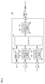
- FIG. 1 is a schematic diagram illustrating a configuration example of a control system 1 according to the present embodiment.
- control system 1 has a plurality of networks, and includes a plurality of devices connected to any one of the networks.
- control system 1 includes a PLC (programmable controller) 2 that is a typical example of a control device, and remote I / O devices 3A, 3B, 3C, and 3D (hereinafter referred to as “remote”) connected to the PLC 2 via a field network. I / O device 3 ").
- the PLC 2 may be further connected to the upper network 4.
- Another PLC may be connected to the higher level network 4, or an arbitrary information processing device such as a gateway server or a database server may be connected.
- the remote I / O devices 3A, 3B, 3C are connected to the PLC 2 via the field network 5.
- the remote I / O device 3A provides another field network 6, and the remote I / O device 3A and the remote I / O device 3D are connected via the field network 6.
- the field network 6 is managed by a communication unit 152 attached to the remote I / O device 3A.
- the PLC 2 can access the remote I / O device 3D via the field network 5 and the field network 6.
- a protocol that typically guarantees communication time between nodes in the network is adopted. That is, a network according to a predetermined protocol is configured between the communication units. As a protocol that guarantees the communication time between the nodes, for example, EtherCAT (registered trademark), EtherNet / IP (registered trademark), DeviceNet (registered trademark), CompoNet (registered trademark), or the like can be adopted. Note that the field network 5 and the field network 6 do not need to adopt the same protocol, and a protocol suitable for each device or unit may be employed.
- the PLC 2 includes a CPU unit 100 and one or a plurality of functional units 150 attached to the CPU unit 100.
- the remote I / O device 3 includes a coupler unit 160 having a communication function and one or a plurality of functional units 150 attached to the coupler unit 160.
- the functional unit 150 is a device for exchanging various types of information with the equipment or machine to be controlled.
- the functional unit 150 includes, for example, a DI (Digital Input) function that receives a digital signal, a DO (Digital Output) function that outputs a digital signal, an AI (Analog Input) function that receives an analog signal, and an AO (Analog Output) that outputs an analog signal. )
- a DI Digital Input
- DO Digital Output
- AI Analog Input
- AO Analog Output
- the functional unit 150 includes a unit that implements special functions such as PID (Proportional Integral Derivative) control and motion control.
- the PLC 2 illustrated in FIG. 1 is an example of a control device, and controls a control target such as equipment or a machine by executing a system program and a user program.
- the PLC 2 typically includes a CPU unit 100 corresponding to a processing unit that executes a system program and a user program, and one or a plurality of functional units 150 attached to the CPU unit 100.
- FIG. 2 is a schematic diagram illustrating an example of a device configuration of the CPU unit 100 configuring the PLC 2 of the control system 1 according to the present embodiment.
- the CPU unit 100 includes a processor 102, a chip set 104, a main memory 106, a nonvolatile memory 108, a clock 110, a communication interface 112, a memory card interface 116, and a network controller 120. , 130 and an internal bus controller 140.
- the processor 102 reads out the system program 108a and the user program 108b stored in the nonvolatile memory 108, develops them in the main memory 106, and in response to the clock supplied from the clock 110, the system program 108a and the user program 108b.
- the instructions contained in are sequentially executed.
- the main memory 106 is configured by a DRAM (Dynamic Random Access Memory), an SRAM (Static Random Access Memory), or the like, and is a storage device that holds a user program, temporary data, and the like.
- the nonvolatile memory 108 is configured by a flash memory or the like, and stores a system program 108a, a user program 108b, and various setting information.
- the chip set 104 supports data exchange between the processor 102 and peripheral devices.
- the communication interface 112 is a circuit for communicating with an external device such as the support device 200, and is connected to the external device via the connector 114.
- a memory card 118 can be attached to the memory card interface 116, and data reading from the memory card 118 and data writing to the memory card 118 are performed.
- the network controllers 120 and 130 control data exchange via the field network 5.
- the network controllers 120 and 130 are connected to the field network 5 via connectors 128 and 138, respectively.
- the network controller 120 includes a buffer memory 122, a transfer control circuit 124, and a DMA control circuit 126 that implements direct memory access (Dynamic Memory Access: DMA).
- the network controller 130 includes a buffer memory 132, a transfer control circuit 134, and a DMA control circuit 136.
- the buffer memories 122 and 132 sequentially store packets transferred through the field network 5.
- the transfer control circuits 124 and 134 control transmission of packets on the field network 5, reception of packets from the field network 5, and the like.
- the DMA control circuits 126 and 136 control access to the buffer memories 122 and 132.
- the internal bus controller 140 is connected to the internal bus via the connector 148, and mediates data exchange with the functional unit 150 attached to the CPU unit 100 via the internal bus.
- the internal bus controller 140 includes a buffer memory 142, a transfer control circuit 144, and a DMA control circuit 146. Since the functions of these parts are the same as the corresponding parts of network controllers 120 and 130, detailed description will not be repeated.
- the network controllers 120 and 130 and the internal bus controller 140 correspond to communication interfaces in order to communicate with the functional unit 150.
- the remote I / O device 3 shown in FIG. 1 is a kind of relay device that can be arranged at a position distant from the PLC 2, collects information indicating the state of equipment or machines to be controlled, etc. And the control output determined by the calculation in the PLC 2 is output as a command to the equipment or machine to be controlled.
- the remote I / O device 3 is attached to the coupler unit 160, which is an example of a communication unit that transfers data between the CPU unit 100 and one or more functional units 150. One or a plurality of functional units 150.
- FIG. 3 is a schematic diagram showing an example of the device configuration of the coupler unit 160 that constitutes the remote I / O device 3 of the control system 1 according to the present embodiment.
- coupler unit 160 includes a controller 161, a communication interface 162, a memory card interface 166, network controllers 170 and 180, and an internal bus controller 190.
- the controller 161 is a circuit in charge of processing in the remote I / O device 3, and typically uses a hard-wired processing circuit such as ASIC (Application Specific Integrated Circuit) or FPGA (Field-Programmable Gate Array). Realized. However, all or some of the functions may be implemented by software (implemented by the processor executing the program).
- ASIC Application Specific Integrated Circuit
- FPGA Field-Programmable Gate Array
- the communication interface 162 is a circuit for communicating with an external device such as the support device 200, similarly to the communication interface 112 shown in FIG. 2, and is connected to the external device via the connector 164.
- the network controllers 170 and 180 control data exchange via the field network 5. More specifically, the network controller 170 includes a buffer memory 172, a transfer control circuit 174, and a DMA control circuit 176. Similarly, the network controller 180 includes a buffer memory 182, a transfer control circuit 184, and a DMA control circuit 186. Since functions of network controllers 170 and 180 are similar to those of network controllers 120 and 130 shown in FIG. 2, detailed description will not be repeated.
- the internal bus controller 190 is connected to the internal bus via the connector 198, and mediates data exchange with the functional unit 150 attached to the coupler unit 160 via the internal bus.
- the internal bus controller 190 includes a buffer memory 192, a transfer control circuit 194, and a DMA control circuit 196. Since the function of each part is the same as the corresponding part of internal bus controller 140 shown in FIG. 2, detailed description will not be repeated.
- a support device 200 can be connected to the PLC 2 or the remote I / O device 3.
- the support device 200 has a function of confirming data and state values held by the PLC 2 and the remote I / O device 3 constituting the control system 1, a function of developing a program executed by the PLC 2, a function of debugging, and the like. provide.
- the support apparatus 200 is typically realized by executing a support program on a personal computer having a general-purpose architecture.
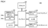
- FIG. 4 is a schematic diagram illustrating an example of a device configuration of the support device 200 of the control system 1 according to the present embodiment.
- support device 200 includes a processor 202, a chipset 204, a main memory 206, a nonvolatile memory 208, a display interface 210, an input unit 212, and a communication interface 214.
- the processor 202 reads an OS (Operating System) 208a and a support program 208b stored in the non-volatile memory 208, and sequentially executes instructions included in the OS 208a and the support program 208b while developing them in the main memory 206.
- the main memory 206 is a storage device that includes a DRAM, an SRAM, or the like, and holds a user program, temporary data, and the like.
- the nonvolatile memory 208 is configured by a flash memory or the like, and stores an OS 208a, a support program 208b, and various setting information.
- the chip set 204 supports data exchange between the processor 202 and peripheral devices.
- the display interface 210 outputs the calculation result by the processor 202 or the like to the display.
- the input unit 212 includes a keyboard and a memory, and accepts user operations.
- the communication interface 214 is a circuit for communicating with the PLC 2 (CPU unit 100).
- FIG. 5 is a diagram illustrating an example of a state in which input data is collected via the remote I / O device 3 of the control system 1 according to the present embodiment.
- FIG. 6 is a diagram showing an example of a user program that uses the input data shown in FIG.
- input data (IN data" in the figure) is input from the field via one functional unit 150 attached to the remote I / O device 3D included in the control system 1.
- any data held by the functional unit 150 can be used.
- input data will be described as an example, but the present invention is not limited to this.
- input data collected by the functional unit 150 includes the internal bus (transmission path 301), the field network 6 and the communication unit 152 (transmission path 302), the remote I / O of the remote I / O device 3D.
- the route taken by the internal bus (transmission route 303) and the field network 5 (transmission route 304) of the apparatus 3A is transferred in order.
- These units and buses function as at least a part of a communication unit that transfers data between the CPU unit 100 and one or more functional units 150.
- the value collected as input data in the CPU unit 100 reflects the value of the input signal that is actually input to the functional unit 150.
- the input data indicates “False”
- a condition indicating that the input data collection path (transmission path) is healthy may be added. It is common.
- information serving as a condition is also referred to as “validity confirmation data”.
- a variable for referring to the value of “validity confirmation data” is also referred to as “validity confirmation variable”.
- status flags 401 to 404 are arranged in series before the input value flag 405.
- the status flags 401 to 404 correspond to validity check variables of the transmission paths 301 to 304 shown in FIG. That is, the state flag 401 indicates the validity (or health or status) of the remote I / O device 3D, the state flag 402 indicates the validity of the field network 6, and the state flag 403 indicates the remote I / O device 3D.
- the validity of the device 3A is shown, and the status flag 404 shows the validity of the field network 5.
- the function block 406 corresponding to the action is activated on the condition of the input value flag 405 indicating the value of the input data.
- a state flag 411 is disposed as a condition in the preceding stage of the input value flag 405 indicating input data.
- the status flag 411 indicates the validity (or soundness or status) of the internal bus of the CPU unit 100.
- control system 1 provides an environment in which special validity check data that summarizes the conditions necessary for evaluating the effectiveness of the target input variable can be used. Is done.
- FIG. 6C shows an example user program 420 using the validity confirmation data provided in the control system 1 according to the present embodiment. More specifically, in the user program 420, the function block 406 corresponding to the action is activated on the condition of the input value flag 405 indicating the value of the input data. A special flag 421 indicating the corresponding valid confirmation data is arranged as a condition in the preceding stage of the input value flag 405 indicating the input data. In this example, the special flag 421 is a set (logical product) of device variables indicating the states of devices existing in the path from the functional unit that fetched the input data to the CPU unit 100.
- a variable (validity confirmation variable) indicating the validity of the data associated with any data held by the functional unit 150
- the specified data is held.
- a function is implemented that reflects the result of aggregating the statuses (values of the status flags) of the communication units existing in the transmission path from the functional unit 150 to the CPU unit 100 as the value (validity confirmation data) indicated by the variable. Is done.
- the developer of the user program can input data input to the functional unit connected to the CPU unit 100 via the internal bus and via one or more networks. It is possible to use abstract validation variables that can absorb differences in hardware configuration and network configuration with input data input to connected functional units, so that the efficiency of programming creation is increased. It is possible to respond flexibly to changes in the network configuration.
- First mounting method As a first mounting method, a method for providing validity check data using only the functions installed in the support device 200 will be described. In the first mounting method, the support device 200 realizes a function of reflecting the valid confirmation variable in the user program as the corresponding valid confirmation data.
- FIG. 7 is a schematic diagram for explaining functions related to creation of a user program in the support apparatus 200 of the control system 1 according to the present embodiment.
- the user creates source code 10 of the user program using an editor provided by support device 200.
- the support device 200 generates an object code 12 by parsing and compiling the source code 10 of the user program.
- the object code 12 of this user program is transferred to the CPU unit 100 of the PLC 2.
- the transferred one or more object codes 12 are stored in the CPU unit 100 as a user program 108b (FIG. 2) and executed.
- the processing of the user program using the validity confirmation data may be realized.
- the support device 200 parses the valid confirmation data or valid confirmation variable included in the source code 10 of the user program and creates an appropriate object code 12, the user is particularly aware at the time of compilation.
- the validity confirmation data can be used without doing so.
- FIG. 8 is a schematic diagram for explaining a first mounting method for providing valid confirmation data in the control system 1 according to the present embodiment.
- a user program 430A as shown in FIG.
- a function block 406 corresponding to an action is activated on condition of an input value flag 405 indicating a value of input data.
- a function block 432 is used to define valid confirmation data for the input value flag 405.
- the function block 432 means an instruction for constructing validity check data according to the present embodiment.
- the function block 432 refers to a transmission path of a variable (variable D1 in the example shown in FIG. 8) defined as input data (IN).
- a variable variable D1 in the example shown in FIG. 8
- input data I
- OUT a value indicating the result of a logical operation (typically logical product) on a set of necessary flags
- the function block 432 included therein includes the variable table 20 defined in advance and With reference to the network configuration 22 or the like, a set of device variables corresponding to the transmission path of the designated variable is specified.
- the variable table 20 associates a variable usable in the user program with a port number of an actual functional unit, and assigns an arbitrary variable name to a value collected at a certain port of a certain functional unit.
- the network configuration 22 defines a connection relationship (network topology) between the CPU unit 100 and each functional unit 150 in the control system 1.
- the support apparatus 200 analyzes the source code 10 of the user program in which the valid confirmation variable is specified, and identifies one or a plurality of communication units related to the determination of the value (valid confirmation data) indicated by the valid confirmation variable.
- a user program 430B as shown in FIG. 8B is generated. That is, the support apparatus 200 adds an instruction to the source code to determine the value indicated by the validity check variable from the set of values indicating the state (status) of the specified one or more communication units (user program) 430B), generating the object code of the user program.
- a special coil 434 corresponding to the function block 432 of the user program 430A is introduced, and a set (logical product) of status flags 401 to 404 is included in the special coil 434.
- the result is stored.
- the user program 430A as exemplified in FIG. 8A is replaced with a special flag 436 indicating a value stored in the special coil 434.
- the function of the validity check data according to the present embodiment is realized.
- the user program 430B may be generated internally and does not need to be displayed in a form that the user can see.
- the contents of the variable table 20 and the network configuration 22 are referred to, and the special flag 436 corresponding to the function block 432 means.
- the content is determined dynamically.
- the support device 200 may be equipped with a function for logging the execution status of the user program in the CPU unit 100.
- a function for logging the execution status of the user program in the CPU unit 100 the value indicated by the special flag 436 shown in FIG. 8B may be displayed as the value of the function block 432 while displaying the user program 430A shown in FIG. .
- the user can confirm whether or not the input value flag 405 is input effectively without being conscious of the details of the contents that the special flag 436 means.
- the function block 432 as described above functions even when input data is fetched from a functional unit attached to the CPU unit 100.
- the function table of the capture destination is specified in the variable table 20, so that the special coil 434 includes the internal unit of the CPU unit 100.
- a state flag indicating the health (status) of the bus is associated.
- FIG. 9 is a flowchart showing a processing procedure according to the first mounting method for providing validity check data in the control system 1 according to the present embodiment.
- Each step shown in FIG. 9 is typically performed by the processor 202 of the support apparatus 200 executing a support program 208b (see FIG. 4) that is an example of a control program.
- support device 200 creates a user program in response to a user operation (step S100). This step S100 is realized by an editor function provided by the support apparatus 200. Subsequently, the support device 200 determines whether compilation is instructed (step S102). If compiling is not instructed (NO in step S102), the processes in and after step S100 are repeated.
- the support apparatus 200 analyzes the source code of the user program and determines whether or not there is a function block indicating the use of the validity check variable (step S104). . If there is no function block indicating the use of the valid confirmation variable (NO in step S104), the processes in steps S106 to S110 are skipped.
- the support apparatus 200 refers to the variable table, the network configuration, and the like to determine the device variable indicated by the function block in the user program.
- a set is specified (step S106).
- the support device 200 holds the specified data when a variable (validity confirmation variable) indicating the validity of the data associated with any data held by the functional unit 150 is specified in the user program.
- the transmission path from the functional unit 150 to the CPU unit 100 and the communication unit existing in the specified transmission path are specified.
- the support apparatus 200 converts the user program into a user program including a valid confirmation variable indicating valid confirmation data including the specified set of device variables (step S108).
- the support device 200 reflects the result of aggregating the status of each identified communication unit as a value (validity confirmation data) indicated by the validity confirmation variable.
- the support device 200 compiles the user program converted in step S108 or the user program created in step S100 to generate an object code of the user program (step S110). Then, the support device 200 transfers the generated object code of the user program to the CPU unit 100 (step S112). Then, the user program creation and compilation process ends.
- Validity confirmation variables may be prepared in advance for all value flags (input value variables). For example, for an input value variable “d0001”, a combination of an identification number assigned to each variable and a character string indicating the type of variable, such as a valid confirmation variable “sst0001”, is used as a variable name. Such one-to-one association is possible.
- each variable may be regarded as an object, and each validity check variable may be designated or used using its property or method.
- the content of the function block defined as the validity confirmation variable is analyzed, and the validity confirmation data is interpreted as a combination of necessary status flags.
- the value of the validity check data is determined in each control cycle with reference to values such as a status flag stored in the CPU unit 100.
- Second mounting method As a second mounting method, a method in which the CPU unit 100 of the PLC 2 and the function installed in the support device 200 cooperate to provide valid confirmation data will be described.
- FIG. 10 is a schematic diagram for explaining processing relating to the second mounting method in the support device 200 of the control system 1 according to the present embodiment.
- the user has created user program 440 using an editor provided by support device 200.
- the validity check variable SST1 (special flag 442) is assigned to the input value flag 405 (variable D1).
- the valid confirmation variable SST1 defined therein includes the variable table 20 and the network configuration 22 defined in advance. Referenced and analyzed as a set of device variables corresponding to the transmission path of the corresponding input value flag 405 (variable D1).
- the variable table 20 associates a variable usable in the user program with a port number of an actual functional unit, and assigns an arbitrary variable name to a value collected at a certain port of a certain functional unit.
- the network configuration 22 defines a connection relationship (network topology) between the CPU unit 100 and each functional unit 150 in the control system 1.
- the validity confirmation data setting 444 is setting information for providing validity confirmation data designated in the CPU unit 100.
- FIG. 11 is a schematic diagram for explaining processing relating to the second mounting method in the control system 1 according to the present embodiment.
- the valid confirmation data setting 444 generated in accordance with the process shown in FIG. 10 includes a definition 444a that the valid confirmation variable is SST1, and status information that constitutes the valid confirmation variable.
- Definition 444b In the definition 444b, for example, a variable name indicating a state flag to be logically ANDed is described.
- the support device 200 analyzes the source code of the user program in which the valid confirmation variable is designated, and determines one or a plurality of communication units related to the determination of the value (valid confirmation data) indicated by the valid confirmation variable. Identify.
- input / output data and status data are arranged on the main memory 106, and each value is input / output refreshed (updated) every control cycle.
- the valid confirmation data setting 444 is transferred from the support device 200 to the CPU unit 100.
- the support device 200 connected to the CPU unit 100 analyzes the source code of the user program and transmits information (validity confirmation data setting 444) specified by the analysis to the CPU unit 100.
- the CPU unit 100 interprets the valid confirmation data setting 444 received from the support device 200 and secures an area for storing the valid confirmation data in a predetermined area on the main memory 106. Validity confirmation data of the variable name designated in the validity confirmation data setting 444 is stored in this secured area.
- data update logic 446 for updating the valid confirmation data is formed in accordance with the state flag definition 444b included in the valid confirmation data setting 444.
- the data update logic 446 is typically executed on the system program 108a, refers to the target state values (values referred to as variables ST1 to ST4) according to the state flag definition 444b, and refers to the state values referred to.
- the result of the logical operation (logical product in this example) is written in the designated area.
- the writing (updating) of the validity confirmation data is preferably repeated at substantially the same control cycle as the input / output refresh.
- the CPU unit 100 adds a function for updating and holding the valid check data indicated by the valid check variable based on the valid check data setting 444 including the specified information.
- variable SST1 Since the valid confirmation data designated in the user program (in this example, variable SST1) is prepared on the CPU unit 100, the logging function 448 implemented in the support device 200 uses the designated valid confirmation variable. With reference, the state value at each timing is presented to the user.
- the support device 200 and the CPU unit 100 of the PLC 2 cooperate to provide valid confirmation data. That is, the CPU unit 100 collects, from the support device 200, the validity confirmation data setting 444 including (1) the variable confirmation variable name and (2) the state value indicating the validity confirmation variable and the definition of the logical operation. . Then, the CPU unit 100 holds and updates the valid confirmation data according to the collected valid confirmation data setting 444.
- the validity confirmation data can be referred to not only from the support device 200 that created the user program 440 but also from an arbitrary external device. , More versatility can be improved. Further, since the validity confirmation data is updated in the CPU unit 100, the validity confirmation data can be updated in the same control cycle as that of the input / output data, and the validity confirmation data can be used for another sequence program.
- FIG. 12 is a flowchart showing a processing procedure according to the second mounting method for providing validity check data in the control system 1 according to the present embodiment.
- the processing procedure shown in FIG. 12 is realized by the cooperation of the support device 200 and the CPU unit 100 of the PLC 2, and each step of the support device 200 is executed by the processor 202 of the support device 200 using the support program 208b (see FIG. 4). Each step of the CPU unit 100 is performed by the processor 102 executing the system program 108a (see FIG. 2).
- support device 200 creates a user program in response to a user operation (step S200). This step S200 is realized by an editor function provided by the support apparatus 200. Subsequently, the support device 200 determines whether or not the reflection to the CPU unit 100 has been instructed (step S202). If the reflection to CPU unit 100 is not instructed (NO in step S202), the processes in and after step S200 are repeated.
- the support device 200 analyzes the source code of the user program and determines whether or not a valid confirmation variable is designated (step S204). . If the valid confirmation variable is not designated (NO in step S204), the processes in steps S206 to S210 are skipped.
- the support apparatus 200 refers to the variable table, the network configuration, and the like to identify a set of device variables indicated by the valid confirmation variable in the user program ( In step S206), a valid confirmation data setting 444 indicating a valid confirmation variable is generated (step S208) and transferred to the CPU unit 100 (step S210).
- the CPU unit 100 secures an area for holding the designated valid confirmation data on the main memory 106 in accordance with the valid confirmation data setting 444 from the support device 200 (step S250) and updates the valid confirmation data.
- the data update logic for this is formed (step S252).
- the CPU unit 100 refers to the designated state value and writes the result of the logical operation for the referenced state value in the area secured as the validity check data (step S254).
- the CPU unit 100 determines whether or not the next control cycle has arrived (step S256). If the next control cycle has arrived (YES in step S256), the process of step S254 is repeated.
- the support device 200 or another external device can obtain the value of the corresponding valid confirmation data by accessing the CPU unit 100 at an arbitrary timing and specifying the valid confirmation variable.
- a function block may be used as exemplified in the first mounting method described above.
- the CPU unit 100 may automatically assign a variable name corresponding to the designated function block.
- each variable may be regarded as an object, and each validity check variable may be designated or used using its property or method.
- the validity confirmation data is held in the CPU unit 100 based on the validity confirmation data setting 444 generated from the information of the user program created by the support device 200. Therefore, the validity check data can be accessed from any external device. Therefore, the availability of the valid confirmation data can be improved. Further, the validity check data held in the CPU unit 100 is updated at the same control cycle as the normal input / output data and the state value, so that it can be used in common among a plurality of abnormality processing logics. .
- Third mounting method As a third mounting method, a method of providing validity check data using only functions that are substantially mounted on the CPU unit 100 of the PLC 2 will be described.
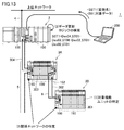
- FIG. 13 is a schematic diagram for explaining a third mounting method for providing valid confirmation data in the control system 1 according to the present embodiment.
- support device 200 determines a valid confirmation variable (in this example, variable SST1) used for reference to valid confirmation data, and the valid confirmation data.
- the input data used for this purpose is transmitted to the CPU unit 100 (valid confirmation variable IN1 in this example).
- the CPU unit 100 specifies a device variable corresponding to the target input data designated by the support device 200, and identifies a target functional unit from the address of the specified device variable ((1) in FIG. 13). . Subsequently, the CPU unit 100 determines to which network the identified functional unit belongs, and identifies a network related to the target functional unit ((2) in FIG. 13). Then, based on the network address and state value address of the functional unit that manages the specified network, the state value and the like necessary for calculating the validity confirmation data are specified, and the data update logic is constructed (FIG. 13). (3)). For example, it is defined that the result of the logical sum for the set of addresses corresponding to the status flags 401 to 404 (variable names ST1 to ST4) is stored as valid confirmation data.
- a variable name indicating valid confirmation data designated by the support device 200 is defined in the CPU unit 100, and logic for updating the defined valid confirmation data in the CPU unit 100. Is built automatically. In searching for a network address as described above, a variable table and a network configuration stored in the CPU unit 100 are referred to.
- variable names used as valid confirmation data and input data to be validated data transmitted from the support device 200 to the CPU unit 100 function blocks in the user program as shown in FIG. May be defined using
- FIG. 14 is a flowchart showing a processing procedure according to the third mounting method for providing validity check data in the control system 1 according to the present embodiment. Each step shown in FIG. 14 is typically performed by the processor 102 of the CPU unit 100 executing the system program 108a (see FIG. 2).
- the CPU unit 100 of the PLC 2 determines whether or not the variable name used as the valid confirmation data and the specification of the input data that is the target of the valid confirmation data are received from the support device 200. (Step S300). If these pieces of information have not been received (NO in step S300), the following processing is skipped.
- step S300 the CPU unit 100 identifies a device variable corresponding to the designated target input data (step S302), and determines the target variable from the address of the identified device variable.
- a functional unit is specified (step S304). Subsequently, the CPU unit 100 determines to which network the identified functional unit belongs (step S306), and identifies a network related to the target functional unit (step S308).
- the CPU unit 100 identifies the functional unit that holds the target data in response to the data that is the target of the valid check data and the variable name that is used as the valid check data associated with the target data. At the same time, the transmission path from the specified functional unit to the CPU unit 100 is specified.
- the CPU unit 100 specifies a state value and the like necessary for calculating the validity confirmation data based on the network address and state value address of the functional unit that manages the specified network (step S310), and data update logic Is constructed (step S312). Then, the CPU unit 100 repeats the update process of the validity check data according to the constructed data update logic (step S314).
- the CPU unit 100 issues a command for updating the result of aggregating the states of the communication units existing in the specified transmission path as a value indicated by the designated validity check variable at predetermined intervals. to add.
- the CPU unit 100 when the support device 200 designates specific input data and designates a valid confirmation variable indicating valid confirmation data associated with the input data, the CPU unit 100 is designated.
- the logic for calculating the valid confirmation data specified in the above is automatically constructed. Therefore, the user can create a user program without considering which hardware is used to collect specified input data. By adopting such a configuration, user program creation efficiency can be increased.
- the validity confirmation data is held in the CPU unit 100, so that the validity confirmation data can be accessed from any external device connected to the CPU unit 100.
- a method for determining a logic or an algorithm for calculating validity check data according to the hardware configuration and network configuration of the control system 1 at the timing when the processing is executed if the hardware configuration or network configuration change such as addition / change / deletion of any unit occurs after the logic or algorithm is determined, the logic is detected by detecting the change. Alternatively, the algorithm may be reconstructed. By adopting such an automatic reconstruction method, a necessary algorithm or logic can be dynamically optimized with respect to the configuration change of the control system 1.
- the user when developing a user program using some input data, the user (typically, the developer of the user program) There is no need to be aware of what hardware and network the input data is collected over. If the user specifies valid confirmation data corresponding to the input data used in the user program, the user can use the valid confirmation data reflecting one or more status information according to the transmission path of the designated input data. it can.
- the value of the validation data is updated based on the logic or algorithm constructed according to the hardware configuration and network configuration of the control system, even if the configuration changes afterwards, the user program It becomes possible to change without changing.
- 1 control system 2 PLC, 3, 3A, 3B, 3C, 3D remote I / O device, 4 upper network, 5, 6 field network, 10 source code, 12 object code, 20 variable table, 22 network configuration, 100 CPU unit, 102, 202 processor, 104, 204 chip set, 106, 206 main memory, 108, 208 nonvolatile memory, 108a system program, 108b, 400, 410, 420, 430A, 430B, 440 user program, 110 clock, 112, 162, 214 communication interface, 114, 128, 138, 148, 164, 198 connector, 116, 166 memory card interface, 118 Memory card, 120, 130, 170, 180 Network controller, 122, 132, 142, 172, 182, 192 Buffer memory, 124, 134, 144, 174, 184, 194 Transfer control circuit, 126, 136, 146, 176 186, 196 DMA control circuit, 140, 190 internal bus controller, 150 functional unit, 152 communication unit,
Landscapes
- Engineering & Computer Science (AREA)
- Software Systems (AREA)
- Physics & Mathematics (AREA)
- General Physics & Mathematics (AREA)
- Theoretical Computer Science (AREA)
- Automation & Control Theory (AREA)
- General Engineering & Computer Science (AREA)
- Computer Networks & Wireless Communication (AREA)
- Signal Processing (AREA)
- Programmable Controllers (AREA)
- Stored Programmes (AREA)
Abstract
制御システムは、ユーザプログラムを実行する処理ユニットと、1または複数の機能ユニットと、処理ユニットと1または複数の機能ユニットとの間でデータを中継する1または複数の通信ユニットと、ユーザプログラムにおいて、機能ユニットが保持するいずれかのデータに関連付けられた当該データの有効性を示す変数が指定されると、指定されたデータを保持する機能ユニットから処理ユニットまでの伝送経路に存在する通信ユニットの各々の状態を集合させた結果を当該変数が示す値として反映する反映手段とを含む。
Description
本発明は、ネットワーク化された制御システム、そのような制御システムに含まれる制御装置、およびそのような制御装置に向けられた制御プログラムに関する。
近年の情報通信技術(ICT:Information and Communication Technology)の進歩に伴って、製造現場で用いられる各種装置のネットワーク化および多機能化が進んでいる。一例として、PLC(プログラマブルコントローラ)などの制御装置、センサやリレーなどのI/O(Input/Output)デバイス、および、インバータやモータドライバなどのアクチュエータなどをネットワークで接続して一体化するようなシステムが実用化されている。
一方で、制御装置で実行されるユーザプログラムにおいては、センサなどの健全性を確認しつつ、処理を実行しなければならないといった要求もある。ネットワーク化された制御システムにおいては、ネットワークに接続されている各機器の状態を収集および監視する必要がある。例えば、特開2007-108923号公報(特許文献1)は、1つのマスタユニットとフィールドバスに接続されるスライス通信ユニットとからなる構成を開示しており、各スライス通信ユニットの状態を状態フラグにより監視可能になっている。
制御システムのネットワーク化が高度化するにつれて、監視対象のユニットなどが増加し、監視対象のすべての健全性を考慮する必要があり、ユーザプログラムの作成効率が低下するといった課題がある。
多段階または高度にネットワーク化された制御システムであっても、効率的なプログラミングを実現できる構成が要望されている。
本発明のある実施の形態に係る制御システムは、ユーザプログラムを実行する処理ユニットと、1または複数の機能ユニットと、処理ユニットと1または複数の機能ユニットとの間でデータを中継する1または複数の通信ユニットと、ユーザプログラムにおいて、機能ユニットが保持するいずれかのデータに関連付けられた当該データの有効性を示す変数が指定されると、指定されたデータを保持する機能ユニットから処理ユニットまでの伝送経路に存在する通信ユニットの各々の状態を集合させた結果を当該変数が示す値として反映する反映手段とを含む。
好ましくは、反映手段は、変数が指定されたユーザプログラムのソースコードを解析して、当該変数が示す値の決定に関連する1または複数の通信ユニットを特定する手段と、特定された1または複数の通信ユニットの状態を示す値の集合から変数が示す値を決定するための命令をソースコードに追加した上で、ユーザプログラムのオブジェクトコードを生成する手段とを含む。
好ましくは、制御システムは、処理ユニットに接続されるサポート装置をさらに含み、反映手段は、サポート装置に実装される。
好ましくは、反映手段は、変数が指定されたユーザプログラムのソースコードを解析して、当該変数が示す値の決定に関連する1または複数の通信ユニットを特定する手段と、処理ユニットにおいて、特定された情報に基づいて、変数が示す値を更新および保持する機能を追加する手段とを含む。
好ましくは、制御システムは、処理ユニットに接続されるサポート装置をさらに含み、サポート装置は、ユーザプログラムのソースコードの解析を実施するとともに、当該解析によって特定された情報を処理ユニットへ送信する。
好ましくは、反映手段は、処理ユニットにおいて、対象のデータおよび当該対象のデータに関連付けられる変数名に応答して、対象のデータを保持する機能ユニットを特定するとともに、当該特定された機能ユニットから処理ユニットまでの伝送経路を特定する手段と、特定された伝送経路に存在する通信ユニットの各々の状態を集合させた結果を指定された変数が示す値として所定周期毎に更新するための命令を追加する手段とを含む。
好ましくは、変数が示す値は、処理ユニットに接続される外部装置からアクセス可能に構成される。
好ましくは、通信ユニットの間は、所定のプロトコルに従うネットワークが構成されている。
本発明のある実施の形態に係る制御装置は、ユーザプログラムを実行する処理ユニットと、1または複数の機能ユニットと通信するための通信インターフェイスとを含む。処理ユニットと1または複数の機能ユニットとの間には、データを中継する1または複数の通信ユニットが配置されている。制御装置は、ユーザプログラムにおいて、機能ユニットが保持するいずれかのデータに関連付けられた当該データの有効性を示す変数が指定されると、指定されたデータを保持する機能ユニットから処理ユニットまでの伝送経路に存在する通信ユニットの各々の状態を集合させた結果を当該変数が示す値として反映する反映手段を含む。
本発明のある実施の形態によれば、コンピュータで実行される制御プログラムが提供さえる。コンピュータは、ユーザプログラムを実行する処理ユニットと、1または複数の機能ユニットと通信するための通信インターフェイスとを含む。処理ユニットと1または複数の機能ユニットとの間には、データを中継する1または複数の通信ユニットが配置されている。制御プログラムはコンピュータに、ユーザプログラムにおいて、機能ユニットが保持するいずれかのデータに関連付けられた当該データの有効性を示す変数が指定されると、指定されたデータを保持する機能ユニットから処理ユニットまでの伝送経路、および、特定された伝送経路に存在する通信ユニットを特定するステップと、特定された各通信ユニットの状態を集合させた結果を当該変数が示す値として反映するステップとを実行させる。
本発明の実施の形態によれば、多段階または高度にネットワーク化された制御システムであっても、効率的なプログラミングを実現できる。
本発明の実施の形態について、図面を参照しながら詳細に説明する。なお、図中の同一または相当部分については、同一符号を付してその説明は繰返さない。
<A.制御システムの構成例>
まず、本実施の形態に係る制御システムの構成例について説明する。図1は、本実施の形態に係る制御システム1の構成例を示す模式図である。図1を参照して、制御システム1は、複数のネットワークを有しており、いずれかのネットワークに接続された複数の装置を含む。
まず、本実施の形態に係る制御システムの構成例について説明する。図1は、本実施の形態に係る制御システム1の構成例を示す模式図である。図1を参照して、制御システム1は、複数のネットワークを有しており、いずれかのネットワークに接続された複数の装置を含む。
一例として、制御システム1は、制御装置の典型例であるPLC(プログラマブルコントローラ)2と、PLC2とフィールドネットワークを介して接続されるリモートI/O装置3A,3B,3C,3D(以下、「リモートI/O装置3」とも総称する。)とを含む。PLC2は、さらに上位ネットワーク4に接続されていてもよい。上位ネットワーク4には、他のPLCが接続されていてもよいし、ゲートウェイサーバやデータベースサーバといった任意の情報処理装置が接続されていてもよい。
より具体的には、リモートI/O装置3A,3B,3Cは、フィールドネットワーク5を介してPLC2と接続されている。リモートI/O装置3Aは別のフィールドネットワーク6を提供しており、フィールドネットワーク6を介して、リモートI/O装置3AとリモートI/O装置3Dとが接続されている。フィールドネットワーク6は、リモートI/O装置3Aに装着された通信ユニット152によって管理される。PLC2は、フィールドネットワーク5およびフィールドネットワーク6を介してリモートI/O装置3Dへアクセス可能になっている。
フィールドネットワーク5,6としては、典型的には、ネットワーク内のノード間の通信時間が保証されるプロトコルが採用される。つまり、通信ユニットの間は、所定のプロトコルに従うネットワークが構成される。このようなノード間の通信時間が保証されるプロトコルとしては、例えば、EtherCAT(登録商標)、EtherNet/IP(登録商標)、DeviceNet(登録商標)、CompoNet(登録商標)などを採用できる。なお、フィールドネットワーク5とフィールドネットワーク6として、同一のプロトコルを採用する必要はなく、それぞれの装置やユニットに適したプロトコルを採用すればよい。
典型的には、PLC2は、CPUユニット100と、CPUユニット100に装着される1または複数の機能ユニット150とから構成される。また、リモートI/O装置3は、通信機能を有するカプラユニット160と、カプラユニット160に装着される1または複数の機能ユニット150とから構成される。
機能ユニット150は、制御対象の設備や機械などとの間で各種情報を遣り取りするための装置である。機能ユニット150は、例えば、デジタル信号を受け取るDI(Digital Input)機能、デジタル信号を出力するDO(Digital Output)機能、アナログ信号を受け取るAI(Analog Input)機能、アナログ信号を出力するAO(Analog Output)機能のうち1または複数の機能を有している。あるいは、機能ユニット150としては、PID(Proportional Integral Derivative)制御やモーション制御といった特殊機能を実装したものを含む。
<B.各装置の装置構成>
次に、制御システム1を構成する各装置の装置構成について説明する。
次に、制御システム1を構成する各装置の装置構成について説明する。
(b1:PLC2)
図1に示すPLC2は、制御装置の一例であり、システムプログラムおよびユーザプログラムを実行することで、設備や機械といった制御対象を制御する。PLC2は、典型的には、システムプログラムおよびユーザプログラムを実行する処理ユニットに相当するCPUユニット100と、CPUユニット100に装着される1または複数の機能ユニット150とから構成される。
図1に示すPLC2は、制御装置の一例であり、システムプログラムおよびユーザプログラムを実行することで、設備や機械といった制御対象を制御する。PLC2は、典型的には、システムプログラムおよびユーザプログラムを実行する処理ユニットに相当するCPUユニット100と、CPUユニット100に装着される1または複数の機能ユニット150とから構成される。
図2は、本実施の形態に係る制御システム1のPLC2を構成するCPUユニット100の装置構成の一例を示す模式図である。図2を参照して、CPUユニット100は、プロセッサ102と、チップセット104と、主メモリ106と、不揮発性メモリ108と、クロック110と、通信インターフェイス112と、メモリカードインターフェイス116と、ネットワークコントローラ120,130と、内部バスコントローラ140とを含む。
プロセッサ102は、不揮発性メモリ108に格納されているシステムプログラム108aおよびユーザプログラム108bを読み出して、主メモリ106に展開しつつ、クロック110から供給されるクロックに応じて、システムプログラム108aおよびユーザプログラム108bに含まれる命令を順次実行する。主メモリ106は、DRAM(Dynamic Random Access Memory)やSRAM(Static Random Access Memory)などで構成され、ユーザプログラムや一時データなどを保持する記憶装置である。不揮発性メモリ108は、フラッシュメモリなどで構成され、システムプログラム108a、ユーザプログラム108b、各種設定情報を格納する。チップセット104は、プロセッサ102と周辺装置とのデータの遣り取りを支援する。
通信インターフェイス112は、サポート装置200などの外部装置と通信するための回路であり、コネクタ114を介して外部装置と接続される。
メモリカードインターフェイス116には、メモリカード118が装着可能になっており、メモリカード118からのデータ読出しおよびメモリカード118へのデータ書込みを行う。
ネットワークコントローラ120,130は、フィールドネットワーク5を介したデータの遣り取りを制御する。ネットワークコントローラ120,130は、コネクタ128,138を介してフィールドネットワーク5とそれぞれ接続される。具体的には、ネットワークコントローラ120は、バッファメモリ122と、転送制御回路124と、ダイレクトメモリアクセス(Dynamic Memory Access:DMA)を実現するDMA制御回路126とを含む。同様に、ネットワークコントローラ130は、バッファメモリ132と、転送制御回路134と、DMA制御回路136とを含む。バッファメモリ122,132は、フィールドネットワーク5を転送されるパケットなどを順次格納する。転送制御回路124,134は、フィールドネットワーク5上へのパケットの送出、および、フィールドネットワーク5からのパケットの受信などを制御する。DMA制御回路126,136は、バッファメモリ122,132へのアクセスを制御する。
内部バスコントローラ140は、コネクタ148を介して内部バスと接続されており、CPUユニット100に装着される機能ユニット150との間の内部バスを介したデータの遣り取りを仲介する。具体的には、内部バスコントローラ140は、バッファメモリ142と、転送制御回路144と、DMA制御回路146とを含む。これらの各部位の機能は、ネットワークコントローラ120,130の対応する部位と同様であるので、詳細な説明は繰返さない。
ネットワークコントローラ120,130および内部バスコントローラ140は、機能ユニット150と通信するために通信インターフェイスに相当する。
(b2:リモートI/O装置3)
図1に示すリモートI/O装置3は、PLC2から離れた位置に配置可能な一種の中継装置であり、制御対象の設備や機械などの状態を示す情報などを収集し、入力データとして、PLC2へ転送するとともに、PLC2での演算により決定された制御出力を制御対象の設備や機械へ指令として出力する。具体的には、リモートI/O装置3は、CPUユニット100と1または複数の機能ユニット150との間でデータを転送する通信ユニットの一例であるカプラユニット160と、カプラユニット160に装着される1または複数の機能ユニット150とを含む。
図1に示すリモートI/O装置3は、PLC2から離れた位置に配置可能な一種の中継装置であり、制御対象の設備や機械などの状態を示す情報などを収集し、入力データとして、PLC2へ転送するとともに、PLC2での演算により決定された制御出力を制御対象の設備や機械へ指令として出力する。具体的には、リモートI/O装置3は、CPUユニット100と1または複数の機能ユニット150との間でデータを転送する通信ユニットの一例であるカプラユニット160と、カプラユニット160に装着される1または複数の機能ユニット150とを含む。
図3は、本実施の形態に係る制御システム1のリモートI/O装置3を構成するカプラユニット160の装置構成の一例を示す模式図である。図3を参照して、カプラユニット160は、コントローラ161と、通信インターフェイス162と、メモリカードインターフェイス166と、ネットワークコントローラ170,180と、内部バスコントローラ190とを含む。
コントローラ161は、リモートI/O装置3における処理を担当する回路であり、典型的には、ASIC(Application Specific Integrated Circuit)やFPGA(Field-Programmable Gate Array)などのハードワイヤードな処理回路を用いて実現される。但し、その全部または一部の機能をソフトウェア実装(プロセッサがプログラムを実行することで実現)してもよい。
通信インターフェイス162は、図2に示す通信インターフェイス112と同様に、サポート装置200などの外部装置と通信するための回路であり、コネクタ164を介して外部装置と接続される。
ネットワークコントローラ170,180は、フィールドネットワーク5を介したデータの遣り取りを制御する。より具体的には、ネットワークコントローラ170は、バッファメモリ172と、転送制御回路174と、DMA制御回路176とを含む。同様に、ネットワークコントローラ180は、バッファメモリ182と、転送制御回路184と、DMA制御回路186とを含む。ネットワークコントローラ170,180の機能は、図2に示すネットワークコントローラ120,130と同様であるので、詳細な説明は繰返さない。
内部バスコントローラ190は、コネクタ198を介して内部バスと接続されており、カプラユニット160に装着される機能ユニット150との間の内部バスを介したデータの遣り取りを仲介する。具体的には、内部バスコントローラ190は、バッファメモリ192と、転送制御回路194と、DMA制御回路196とを含む。これらの各部位の機能は、図2に示す内部バスコントローラ140の対応する部位と同様であるので、詳細な説明は繰返さない。
(b3:サポート装置200)
図1に示すように、PLC2またはリモートI/O装置3には、サポート装置200が接続可能になっている。サポート装置200は、制御システム1を構成するPLC2およびリモートI/O装置3が保持しているデータや状態値を確認する機能や、PLC2で実行されるプログラムを開発する機能およびデバックする機能などを提供する。サポート装置200は、典型的には、汎用的なアーキクテチャを有するパーソナルコンピュータ上で、サポートプログラムが実行されることで実現される。
図1に示すように、PLC2またはリモートI/O装置3には、サポート装置200が接続可能になっている。サポート装置200は、制御システム1を構成するPLC2およびリモートI/O装置3が保持しているデータや状態値を確認する機能や、PLC2で実行されるプログラムを開発する機能およびデバックする機能などを提供する。サポート装置200は、典型的には、汎用的なアーキクテチャを有するパーソナルコンピュータ上で、サポートプログラムが実行されることで実現される。
図4は、本実施の形態に係る制御システム1のサポート装置200の装置構成の一例を示す模式図である。図4を参照して、サポート装置200は、プロセッサ202と、チップセット204と、主メモリ206と、不揮発性メモリ208と、表示インターフェイス210と、入力部212と、通信インターフェイス214とを含む。
プロセッサ202は、不揮発性メモリ208に格納されているOS(Operating System)208aおよびサポートプログラム208bを読み出して、主メモリ206に展開しつつ、OS208aおよびサポートプログラム208bに含まれる命令を順次実行する。主メモリ206は、DRAMやSRAMなどで構成され、ユーザプログラムや一時データなどを保持する記憶装置である。不揮発性メモリ208は、フラッシュメモリなどで構成され、OS208a、サポートプログラム208b、各種設定情報を格納する。チップセット204は、プロセッサ202と周辺装置とのデータの遣り取りを支援する。
表示インターフェイス210は、プロセッサ202などによる演算結果をディスプレイへ出力する。入力部212は、キーボードやメモリなどからなり、ユーザの操作を受付ける。通信インターフェイス214は、PLC2(CPUユニット100)と通信するための回路である。
<C.概要>
次に、本実施の形態に係る制御システム1において提供される機能の概要を説明する。
次に、本実施の形態に係る制御システム1において提供される機能の概要を説明する。
図5は、本実施の形態に係る制御システム1のリモートI/O装置3を介して入力データを収集する状態の一例を示す図である。図6は、図5に示す入力データを利用するユーザプログラムの一例を示す図である。
図5に示すように、一例として、制御システム1に含まれるリモートI/O装置3Dに装着された1つの機能ユニット150を介して、フィールドから入力データ(図中においては、「INデータ」とも記す。)を収集する場合を考える。なお、CPUユニット100においては、機能ユニット150が保持する任意のデータを利用可能であり、以下では、典型例として入力データを例に説明するが、これに限られるものではない。
図5に示す例では、機能ユニット150で収集された入力データは、リモートI/O装置3Dの内部バス(伝送経路301)、フィールドネットワーク6および通信ユニット152(伝送経路302)、リモートI/O装置3Aの内部バス(伝送経路303)、フィールドネットワーク5(伝送経路304)とった経路を順に転送されることになる。これらユニットおよびバスが、CPUユニット100と1または複数の機能ユニット150との間でデータを転送する通信ユニットの少なくとも一部として機能する。
一般的には、CPUユニット100において入力データとして収集される値が、現実に機能ユニット150に入力される入力信号の値を反映したものであることをユーザプログラム上で確かにしておく必要がある。これは、例えば、入力データが「False」を示す場合、対応する機能ユニット150に入力される入力信号が現実に「False」であることを反映したものであるのか、入力データが伝送経路を順次転送される過程において何らかの異常があって伝送ができないため、入力信号は「True」であるにもかかわらず、CPUユニット100において入力データが誤って「False」となっているのかを判断することができないためである。
そこで、一般的には、入力データを用いて何らかの処理(アクション)を実行する命令を記述する際には、入力データの収集経路(伝送経路)が健全であることを示す条件を付加することが一般的である。このような条件となる情報を、以下では「有効確認データ」とも称す。また、本実施の形態においては、基本的には変数プログラミングにてユーザプログラムが作成されるので、「有効確認データ」の値を参照するための変数を「有効確認変数」とも称す。
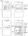
図6(A)に示すユーザプログラム400においては、何らかのアクションの実行/停止を入力データに値に関連付けた例を示す。すなわち、入力データの値を示す入力値フラグ405を条件として、アクションに対応するファンクションブロック406が活性化されるようになっている。
さらに、入力値フラグ405の前段には、状態フラグ401~404(変数名ST1~ST4)が直列に配置されている。状態フラグ401~404は、図5に示す伝送経路301~304の有効確認変数にそれぞれ相当する。すなわち、状態フラグ401は、リモートI/O装置3Dの有効性(または、健全性あるいはステータス)を示し、状態フラグ402は、フィールドネットワーク6の有効性を示し、状態フラグ403は、リモートI/O装置3Aの有効性を示し、状態フラグ404は、フィールドネットワーク5の有効性を示す。
一方、図6(B)に示すユーザプログラム410においては、入力データをCPUユニット100に装着された機能ユニットから取り込む場合の例を示す。この例においても、入力データの値を示す入力値フラグ405を条件として、アクションに対応するファンクションブロック406が活性化されるようになっている。そして、入力データを示す入力値フラグ405の前段には、状態フラグ411が条件として配置されている。状態フラグ411は、CPUユニット100の内部バスの有効性(または、健全性あるいはステータス)を示す。
図6(A)と図6(B)とを比較すると分かるように、対象の入力データがCPUユニット100に伝送するまでの経路を構成するネットワーク階層数が多くなるほど、有効確認データとして、より多くのフラグを設定する必要が生じる。
制御システムのネットワーク化が高度化するにつれて、各フラグによって何が定義されているかを確かめる必要があり、かつ、ネットワーク構成が変更された場合には、それに応じて、有効確認データとして用いるべきフラグを変更し、ユーザプログラム410を更新しなければならなくなる。
このような課題に対して、本実施の形態に係る制御システム1においては、対象となる入力変数の有効性を評価するために必要な条件をまとめた特殊な有効確認データを利用できる環境が提供される。
図6(C)は、本実施の形態に係る制御システム1において提供される有効確認データを用いた一例としてのユーザプログラム420を示す。より具体的には、ユーザプログラム420においては、入力データの値を示す入力値フラグ405を条件として、アクションに対応するファンクションブロック406が活性化されるようになっている。そして、入力データを示す入力値フラグ405の前段には、対応する有効確認データを示す特殊フラグ421が条件として配置されている。この例においては、特殊フラグ421は、入力データを取り込んだ機能ユニットからCPUユニット100までの経路に存在するデバイスの状態を示すデバイス変数の集合(論理積)となっている。
本実施の形態においては、ユーザプログラムにおいて、機能ユニット150が保持するいずれかのデータに関連付けられた当該データの有効性を示す変数(有効確認変数)が指定されると、指定されたデータを保持する機能ユニット150からCPUユニット100までの伝送経路に存在する通信ユニットの各々の状態(各状態フラグの値)を集合させた結果を当該変数が示す値(有効確認データ)として反映する機能が実装される。
このような特殊な有効確認データを利用できることで、ユーザプログラムの開発者は、CPUユニット100と内部バスを介して接続された機能ユニットに入力される入力データと、1または複数のネットワークを介して接続された機能ユニットに入力される入力データとの間で、ハードウェア構成およびネットワーク構成の相違を吸収可能な、抽象化された有効確認変数を用いることができるので、プログラミングの作成効率を高めることができるとともに、ネットワーク構成の変更などにもフレキシブルに対応できる。
以下、本実施の形態に係る有効確認データを提供するためのいくつかの実装方法について説明する。
<D.第1の実装方法>
第1の実装方法として、サポート装置200に搭載される機能のみを用いて有効確認データを提供する方法について説明する。第1の実装方法においては、ユーザプログラム中の有効確認変数が対応の有効確認データとして反映する機能をサポート装置200で実現する。
第1の実装方法として、サポート装置200に搭載される機能のみを用いて有効確認データを提供する方法について説明する。第1の実装方法においては、ユーザプログラム中の有効確認変数が対応の有効確認データとして反映する機能をサポート装置200で実現する。
図7は、本実施の形態に係る制御システム1のサポート装置200におけるユーザプログラムの作成に係る機能を説明するための模式図である。図7を参照して、ユーザは、サポート装置200が提供するエディタを用いてユーザプログラムのソースコード10を作成する。サポート装置200は、ユーザ操作を受けて、ユーザプログラムのソースコード10をパーサ(構文解析)およびコンパイルしてオブジェクトコード12を生成する。このユーザプログラムのオブジェクトコード12は、PLC2のCPUユニット100へ転送される。転送された1または複数のオブジェクトコード12がユーザプログラム108b(図2)としてCPUユニット100に格納され、実行される。
ユーザプログラムのソースコード10がパースおよびコンパイルされるときに、本実施の形態に係る有効確認データを用いた記述があれば、その有効確認データが意図する内容を既存の命令の組み合わせに分解することで、有効確認データを用いたユーザプログラムの処理を実現するようにしてもよい。ユーザプログラムのソースコード10に含まれる有効確認データまたは有効確認変数をサポート装置200がパースして、適切なオブジェクトコード12を作成するという方法を採用することで、ユーザは、コンパイル時などに特に意識することなく、有効確認データを利用することができる。
図8は、本実施の形態に係る制御システム1における有効確認データを提供するための第1の実装方法を説明するための模式図である。例えば、図8(A)に示すようなユーザプログラム430Aが作成されたとする。ユーザプログラム430Aにおいては、入力データの値を示す入力値フラグ405を条件として、アクションに対応するファンクションブロック406が活性化されるようになっている。入力値フラグ405についての有効確認データを定義するために、ファンクションブロック432が用いられている。ファンクションブロック432は、本実施の形態に係る有効確認データを構築するための命令を意味する。
より具体的には、ファンクションブロック432は、入力(EXE)が活性化されると、入力データ(IN)として定義される変数(図8に示す例では、変数D1)の伝送経路などが参照されて、必要なフラグの集合に対する論理演算(典型的には、論理積)の結果を示す値を出力する(OUT)ことを定義する。
より具体的には、図8(A)に例示されるようなユーザプログラム430Aのソースコードがパースされる際には、その中に含まれるファンクションブロック432は、予め定義されている変数テーブル20およびネットワークコンフィギュレーション22などが参照されて、指定された変数の伝送経路に応じたデバイス変数の集合が特定される。
変数テーブル20は、ユーザプログラムで利用可能な変数と現実の機能ユニットのポート番号とを関連付けるものであり、ある機能ユニットのあるポートにて収集される値に対して、任意の変数名の割り当てを定義する。ネットワークコンフィギュレーション22は、制御システム1におけるCPUユニット100と各機能ユニット150との間の接続関係(ネットワークトポロジー)などを定義する。
典型的には、変数テーブル20およびネットワークコンフィギュレーション22が参照されることで、ファンクションブロック432の出力値を決定するために必要なフラグを特定することができる。サポート装置200は、有効確認変数が指定されたユーザプログラムのソースコード10を解析して、当該有効確認変数が示す値(有効確認データ)の決定に関連する1または複数の通信ユニットを特定する。
このようなファンクションブロック432の出力値を決定するために必要なフラグが特定されると、図8(B)に示すようなユーザプログラム430Bが生成される。つまり、サポート装置200は、特定された1または複数の通信ユニットの状態(ステータス)を示す値の集合から有効確認変数が示す値を決定するための命令をソースコードに追加した上で(ユーザプログラム430B)、ユーザプログラムのオブジェクトコードを生成する。
より具体的には、ユーザプログラム430Bにおいては、ユーザプログラム430Aのファンクションブロック432に対応する特殊コイル434が導入されており、この特殊コイル434には、状態フラグ401~404の集合(論理積)の結果が格納される。そして、図8(A)に例示されるようなユーザプログラム430Aは、特殊コイル434に格納された値を示す特殊フラグ436に置換される。最終的に、図8(B)に示すようなユーザプログラム430Bがコンパイルされることで、本実施の形態に係る有効確認データの機能が実現される。
なお、ユーザプログラム430Bは、内部的に生成すればよく、ユーザが見えるような形態で表示などを行う必要はない。
第1の実装方法によれば、ファンクションブロック432を含むユーザプログラムがパースされる際に、変数テーブル20およびネットワークコンフィギュレーション22の内容が参照されて、ファンクションブロック432に対応する特殊フラグ436が意味する内容が動的に決定される。このような有効確認データの内容を動的に決定する処理を採用することで、ユーザは、各変数がいずれの機能ユニットに関連付けられているのか、および、当該変数が関連付けられている機能ユニットがいずれのネットワーク上に存在するのか、といったことを気にすることなく、実行条件とすべき有効確認変数を利用できる。
サポート装置200には、CPUユニット100でのユーザプログラムの実行状態をロギングする機能が実装されている場合もある。このようなロギング機能においては、図8(A)に示すユーザプログラム430Aを表示しつつ、図8(B)に示す特殊フラグ436が示す値をファンクションブロック432の値として表示するようにしてもよい。このようなロギング機能を利用することで、ユーザは、特殊フラグ436が意味する内容の詳細を意識することなく、入力値フラグ405が有効に入力されているか否かを確認できる。
図6(B)に示すように、入力データがCPUユニット100に装着された機能ユニットから取り込まれる場合であっても、上述したようなファンクションブロック432は機能する。CPUユニット100に装着された機能ユニットから入力データが取り込まれる場合には、例えば、変数テーブル20にて、取り込み先の機能ユニットが指定されているので、特殊コイル434には、CPUユニット100の内部バスの健全性(ステータス)を示す状態フラグが関連付けられる。
次に、第1の実装方法に係る処理手順について説明する。図9は、本実施の形態に係る制御システム1における有効確認データを提供するための第1の実装方法に係る処理手順を示すフローチャートである。図9に示す各ステップは、典型的には、サポート装置200のプロセッサ202が制御プログラムの一例であるサポートプログラム208b(図4参照)を実行することで実施される。
図9を参照して、サポート装置200は、ユーザ操作に応じて、ユーザプログラムを作成する(ステップS100)。このステップS100は、サポート装置200が提供するエディタ機能によって実現される。続いて、サポート装置200は、コンパイルが指示されたか否かを判断する(ステップS102)。コンパイルが指示されていなければ(ステップS102においてNO)、ステップS100以下の処理が繰返される。
コンパイルが指示されると(ステップS102においてYES)、サポート装置200は、ユーザプログラムのソースコードを解析して、有効確認変数の使用を示すファンクションブロックが存在するか否かを判断する(ステップS104)。有効確認変数の使用を示すファンクションブロックが存在しなければ(ステップS104においてNO)、ステップS106~S110の処理はスキップされる。
有効確認変数の使用を示すファンクションブロックが存在していれば(ステップS104においてYES)、サポート装置200は、変数テーブルおよびネットワークコンフィギュレーションなどを参照して、ユーザプログラム中のファンクションブロックが示すデバイス変数の集合を特定する(ステップS106)。つまり、サポート装置200は、ユーザプログラムにおいて、機能ユニット150が保持するいずれかのデータに関連付けられた当該データの有効性を示す変数(有効確認変数)が指定されると、指定されたデータを保持する機能ユニット150からCPUユニット100までの伝送経路、および、特定された伝送経路に存在する通信ユニットを特定する。
そして、サポート装置200は、ユーザプログラムを当該特定されたデバイス変数の集合からなる有効確認データを示す有効確認変数を含むユーザプログラムに変換する(ステップS108)。これによって、サポート装置200は、特定された各通信ユニットの状態を集合させた結果を有効確認変数が示す値(有効確認データ)として反映する。
サポート装置200は、ステップS108において変換されたユーザプログラム、または、ステップS100において作成されたユーザプログラムをコンパイルして、ユーザプログラムのオブジェクトコードを生成する(ステップS110)。そして、サポート装置200は、生成したユーザプログラムのオブジェクトコードをCPUユニット100へ転送する(ステップS112)。そして、ユーザプログラムの作成およびコンパイルの処理は終了する。
上述の説明においては、有効確認変数を示すファンクションブロックを用いることで、対象となる有効確認データを動的に決定できる実装例を例示したがこれに限らず、CPUユニット100で扱うことのできる入力値フラグ(入力値変数)のすべてについて有効確認変数を予め用意しておいてもよい。例えば、入力値変数「d0001」に対して、有効確認変数「sst0001」といったように、変数毎に割当てた識別番号と変数の種類を示す文字列との組み合わせを変数名として利用することで、このような一対一の対応付けが可能になる。あるいは、各変数をオブジェクトとしてみなし、そのプロパティまたはメソッドなどを用いて、各有効確認変数を指定または利用するようにしてもよい。
いずれの方法であっても、プログラミング上の表現方法の違いであり、上述と同様の方法で実装できる。
上述したように、第1の実装方法においては、有効確認変数として定義されるファンクションブロックの内容が解析されて、必要な状態フラグの組み合わせとして有効確認データが解釈される。そして、有効確認データの値は、CPUユニット100に格納されている状態フラグなどの値を参照して各制御周期において決定されることになる。このような方法を採用することで、有効確認データを保持するための領域をCPUユニット100上に用意する必要はないので、CPUユニット100のメモリリソースが不足するような事態を回避しつつ、多段階または高度にネットワーク化された制御システムであっても、効率的なプログラミングを実現できる。
<E.第2の実装方法>
第2の実装方法として、PLC2のCPUユニット100とサポート装置200に搭載された機能とが連携して、有効確認データを提供する方法について説明する。
第2の実装方法として、PLC2のCPUユニット100とサポート装置200に搭載された機能とが連携して、有効確認データを提供する方法について説明する。
図10は、本実施の形態に係る制御システム1のサポート装置200における第2の実装方法に関する処理を説明するための模式図である。図10を参照して、ユーザは、サポート装置200が提供するエディタを用いてユーザプログラム440を作成したとする。ここで、入力値フラグ405(変数D1)に対して有効確認変数SST1(特殊フラグ442)が割当てられているとする。
図10に例示されるようなユーザプログラム440のソースコードがパースされる際には、その中に定義されている有効確認変数SST1は、予め定義されている変数テーブル20およびネットワークコンフィギュレーション22などが参照されて、対応する入力値フラグ405(変数D1)の伝送経路に応じたデバイス変数の集合として解析される。
変数テーブル20は、ユーザプログラムで利用可能な変数と現実の機能ユニットのポート番号とを関連付けるものであり、ある機能ユニットのあるポートにて収集される値に対して、任意の変数名の割り当てを定義する。ネットワークコンフィギュレーション22は、制御システム1におけるCPUユニット100と各機能ユニット150との間の接続関係(ネットワークトポロジー)などを定義する。
典型的には、変数テーブル20およびネットワークコンフィギュレーション22が参照されることで、有効確認変数(特殊フラグ442)の出力値を決定するために必要なステータス情報を特定することができる。有効確認変数の出力値を決定するために必要なフラグが特定されると、対象の特殊フラグ442を実現するための有効確認データ設定444が生成される。有効確認データ設定444は、CPUユニット100において指定された有効確認データを提供するための設定情報である。
図11は、本実施の形態に係る制御システム1における第2の実装方法に関する処理を説明するための模式図である。図10に示すような処理に従って生成された有効確認データ設定444は、図11(A)に示すように、有効確認変数がSST1であるとの定義444aと、有効確認変数を構成するステータス情報の定義444bとを含む。定義444bにおいては、例えば、論理積をとる対象となる状態フラグを示す変数名が記述される。このように、サポート装置200は、有効確認変数が指定されたユーザプログラムのソースコードを解析して、当該有効確認変数が示す値(有効確認データ)の決定に関連する1または複数の通信ユニットを特定する。
CPUユニット100においては、入出力データおよびステータスデータが主メモリ106上に配置されており、それぞれの値は制御周期毎に入出力リフレッシュ(更新)される。
有効確認データ設定444は、サポート装置200からCPUユニット100へ転送される。このように、CPUユニット100に接続されるサポート装置200は、ユーザプログラムのソースコードの解析を実施するとともに、当該解析によって特定された情報(有効確認データ設定444)をCPUユニット100へ送信する。
CPUユニット100は、サポート装置200から受信した有効確認データ設定444を解釈し、主メモリ106上の所定領域に有効確認データを格納するための領域を確保する。この確保された領域上に、有効確認データ設定444にて指定された変数名の有効確認データが格納されるようになる。
さらに、図4(B)に示すように、CPUユニット100においては、有効確認データ設定444に含まれる状態フラグの定義444bに従って、有効確認データを更新するためのデータ更新ロジック446が形成される。データ更新ロジック446は、典型的には、システムプログラム108a上で実行され、状態フラグの定義444bに従って対象となる状態値(変数ST1~ST4として参照される値)を参照し、参照した状態値についての論理演算(この例では、論理積)の結果を指定された領域に書込む。この有効確認データの書込み(更新)についても、入出力リフレッシュと実質的に同じ制御周期で繰返されることが好ましい。
このように、CPUユニット100は、特定された情報を含む有効確認データ設定444に基づいて、有効確認変数が示す有効確認データを更新および保持する機能を追加する。
ユーザプログラム上で指定された有効確認データ(この例では、変数SST1)がCPUユニット100上に用意されているので、サポート装置200に実装されるロギング機能448は、この指定された有効確認変数を参照して、各タイミングにおける状態値をユーザに提示する。
第2の実装方法によれば、サポート装置200とPLC2のCPUユニット100とが連携して有効確認データを提供することになる。すなわち、CPUユニット100は、サポート装置200から、(1)有効確認変数の変数名、および、(2)有効確認変数を示す状態値および論理演算の定義、を含む有効確認データ設定444を収集する。そして、CPUユニット100は、収集した有効確認データ設定444に従って、有効確認データの保持および更新を行う。
第2の実装方法によれば、CPUユニット100が有効確認データを保持および更新することになるので、ユーザプログラム440を作成したサポート装置200に限らず、任意の外部装置から有効確認データを参照でき、より汎用性を高めることができる。また、CPUユニット100において有効確認データが更新されるので、入出力データと同様の制御周期で有効確認データを更新でき、当該有効確認データを別のシーケンスプログラムにも利用できる。
次に、第2の実装方法に係る処理手順について説明する。図12は、本実施の形態に係る制御システム1における有効確認データを提供するための第2の実装方法に係る処理手順を示すフローチャートである。図12に示す処理手順は、サポート装置200とPLC2のCPUユニット100とが連携することによって実現され、サポート装置200の各ステップは、サポート装置200のプロセッサ202がサポートプログラム208b(図4参照)を実行することで実施され、CPUユニット100の各ステップは、プロセッサ102がシステムプログラム108a(図2参照)を実行することで実施される。
図12を参照して、サポート装置200は、ユーザ操作に応じて、ユーザプログラムを作成する(ステップS200)。このステップS200は、サポート装置200が提供するエディタ機能によって実現される。続いて、サポート装置200は、CPUユニット100への反映が指示されたか否かを判断する(ステップS202)。CPUユニット100への反映が指示されていなければ(ステップS202においてNO)、ステップS200以下の処理が繰返される。
CPUユニット100への反映が指示されると(ステップS202においてYES)、サポート装置200は、ユーザプログラムのソースコードを解析して、有効確認変数が指定されているか否かを判断する(ステップS204)。有効確認変数が指定されていなければ(ステップS204においてNO)、ステップS206~S210の処理はスキップされる。
有効確認変数が指定されていれば(ステップS204においてYES)、サポート装置200は、変数テーブルおよびネットワークコンフィギュレーションなどを参照して、ユーザプログラム中の有効確認変数が示すデバイス変数の集合を特定し(ステップS206)、有効確認変数を示す有効確認データ設定444を生成し(ステップS208)、CPUユニット100へ転送する(ステップS210)。
CPUユニット100は、サポート装置200からの有効確認データ設定444に応じて、指定された有効確認データを保持するための領域を主メモリ106上に確保する(ステップS250)とともに、有効確認データを更新するためのデータ更新ロジックを形成する(ステップS252)。そして、CPUユニット100は、指定された状態値を参照し、参照した状態値についての論理演算の結果を有効確認データとして確保した領域に書込む(ステップS254)。CPUユニット100は、次の制御周期が到来したか否かを判断し(ステップS256)、次の制御周期が到来すれば(ステップS256においてYES)、ステップS254の処理を繰返す。
サポート装置200または他の外部装置は、任意のタイミングでCPUユニット100へアクセスして、有効確認変数を指定することで、対応の有効確認データの値を取得できる。
なお、上述の説明においては、ユーザプログラムにおいて有効確認変数を用いる例を示したが、これに代えて、上述した第1の実装方法において例示したがファンクションブロックを用いるようにしてもよい。ファンクションブロックを用いる場合には、CPUユニット100が指定されたファンクションブロックに対応する変数名を自動的に割当てるようにしてもよい。あるいは、各変数をオブジェクトとしてみなし、そのプロパティまたはメソッドなどを用いて、各有効確認変数を指定または利用するようにしてもよい。
いずれの方法であっても、プログラミング上の表現方法の違いであり、上述と同様の方法で実装できる。
上述したように、第2の実装方法においては、サポート装置200にて作成されたユーザプログラムの情報から生成される有効確認データ設定444に基づいて、CPUユニット100内部に有効確認データが保持されるので、任意の外部装置から当該有効確認データにアクセスできる。そのため、有効確認データの利用性を高めることができる。また、CPUユニット100内部に保持される有効確認データは、通常の入出力データおよび状態値と同様の制御周期で更新されるので、複数の異常処理ロジックの間で共通して利用することもできる。
<F.第3の実装方法>
第3の実装方法として、実質的にPLC2のCPUユニット100に搭載される機能のみを用いて有効確認データを提供する方法について説明する。
第3の実装方法として、実質的にPLC2のCPUユニット100に搭載される機能のみを用いて有効確認データを提供する方法について説明する。
図13は、本実施の形態に係る制御システム1における有効確認データを提供するための第3の実装方法を説明するための模式図である。図13を参照して、第3の実装方法においては、サポート装置200は、有効確認データへの参照に用いられる有効確認変数(この例では、変数SST1)、および、当該有効確認データを決定するために用いられる入力データの特定(この例では、有効確認変数IN1)をCPUユニット100へ送信する。
CPUユニット100は、サポート装置200から指定された対象の入力データに対応するデバイス変数を特定するとともに、特定されたデバイス変数のアドレスから、対象の機能ユニットを特定する(図13の(1))。続いて、CPUユニット100は、特定された機能ユニットがいずれのネットワークに属しているのかを判断し、対象の機能ユニットに関連するネットワークを特定する(図13の(2))。そして、特定されたネットワークを管理する機能ユニットのネットワークアドレスおよび状態値アドレスなどに基づいて、有効確認データを算出するために必要な状態値などを特定し、データ更新ロジックを構築する(図13の(3))。例えば、状態フラグ401~404(変数名ST1~ST4)にそれぞれ対応するアドレスの集合に対する論理和の結果が有効確認データとして格納されることが定義される。
このような手順に従って、サポート装置200から指定された有効確認データを示す変数名がCPUユニット100内において定義されるとともに、CPUユニット100内では、当該定義された有効確認データを更新するためのロジックが自動的に構築される。上述のようなネットワークアドレスの探索には、CPUユニット100に格納されている変数テーブルおよびネットワークコンフィギュレーションなどが参照される。
サポート装置200からCPUユニット100へ送信される、有効確認データとして用いる変数名、および、当該有効確認データの対象となる入力データについては、図8(A)に示すようなユーザプログラム中のファンクションブロックを用いて定義されてもよい。
次に、第3の実装方法に係る処理手順について説明する。図14は、本実施の形態に係る制御システム1における有効確認データを提供するための第3の実装方法に係る処理手順を示すフローチャートである。図14に示す各ステップは、典型的には、CPUユニット100のプロセッサ102がシステムプログラム108a(図2参照)を実行することで実施される。
図14を参照して、PLC2のCPUユニット100は、サポート装置200から、有効確認データとして用いる変数名、および、当該有効確認データの対象となる入力データの特定を受信したか否かを判断する(ステップS300)。これらの情報を受信していなければ(ステップS300においてNO)、以下の処理はスキップされる。
これらの情報を受信すれば(ステップS300においてYES)、CPUユニット100は、指定された対象の入力データに対応するデバイス変数を特定し(ステップS302)、特定されたデバイス変数のアドレスから、対象の機能ユニットを特定する(ステップS304)。続いて、CPUユニット100は、特定された機能ユニットがいずれのネットワークに属しているのかを判断し(ステップS306)、対象の機能ユニットに関連するネットワークを特定する(ステップS308)。
このように、CPUユニット100は、当該有効確認データの対象となるデータおよび当該対象のデータに関連付けられる有効確認データとして用いる変数名に応答して、当該対象のデータを保持する機能ユニットを特定するとともに、当該特定された機能ユニットからCPUユニット100までの伝送経路を特定する。
CPUユニット100は、特定されたネットワークを管理する機能ユニットのネットワークアドレスおよび状態値アドレスなどに基づいて、有効確認データを算出するために必要な状態値などを特定し(ステップS310)、データ更新ロジックを構築する(ステップS312)。そして、CPUユニット100は、構築したデータ更新ロジックに従って、有効確認データの更新処理を繰返す(ステップS314)。
このように、CPUユニット100は、特定された伝送経路に存在する通信ユニットの各々の状態を集合させた結果を、指定された有効確認変数が示す値として所定周期毎に更新するための命令を追加する。
上述したように、第3の実装方法においては、サポート装置200にて、特定の入力データを指定するとともに、当該入力データに関連付けられる有効確認データを示す有効確認変数を指定すると、CPUユニット100にて指定された有効確認データを算出するためのロジックが自動的に構築される。そのため、ユーザは、指定した入力データがいずれのハードウェアを用いて収集されているのかといったことを考慮することなく、ユーザプログラムを作成できる。このような構成を採用することで、ユーザプログラムの作成効率を高めることができる。また、第3の実装方法においては、CPUユニット100内部に有効確認データが保持されるので、CPUユニット100に接続される任意の外部装置から当該有効確認データにアクセス可能になっている。
<G.その他の実装例>
上述の第1~第3の実装例においては、処理が実行されたタイミングにおける制御システム1のハードウェア構成およびネットワーク構成に応じて、有効確認データを算出するためのロジックまたはアルゴリズムを決定する方法について例示したが、そのロジックまたはアルゴリズムを決定した後、何らかのユニットの追加・変更・廃止といった、ハードウェア構成あるいはネットワーク構成の変更が生じた場合には、その変更が生じたことを検知して、ロジックまたはアルゴリズムを再構築するようにしてもよい。このような自動再構築の方法を採用することで、制御システム1の構成変更に対して、必要なアルゴリズムまたはロジックを動的に最適化できる。
上述の第1~第3の実装例においては、処理が実行されたタイミングにおける制御システム1のハードウェア構成およびネットワーク構成に応じて、有効確認データを算出するためのロジックまたはアルゴリズムを決定する方法について例示したが、そのロジックまたはアルゴリズムを決定した後、何らかのユニットの追加・変更・廃止といった、ハードウェア構成あるいはネットワーク構成の変更が生じた場合には、その変更が生じたことを検知して、ロジックまたはアルゴリズムを再構築するようにしてもよい。このような自動再構築の方法を採用することで、制御システム1の構成変更に対して、必要なアルゴリズムまたはロジックを動的に最適化できる。
<H.利点>
本実施の形態に係る生産システムおよび当該制御システムを構成する制御装置によれば、何らかの入力データを利用したユーザプログラムを開発するにあたって、ユーザ(典型的には、ユーザプログラムの開発者)は、当該入力データがどのようなハードウェアおよびネットワークを介して収集されるのかを意識する必要がない。ユーザは、ユーザプログラムにおいて使用する入力データに対応する有効確認データを指定すれば、当該指定した入力データの伝送経路などに応じた1または複数のステータス情報を反映した有効確認データを利用することができる。
本実施の形態に係る生産システムおよび当該制御システムを構成する制御装置によれば、何らかの入力データを利用したユーザプログラムを開発するにあたって、ユーザ(典型的には、ユーザプログラムの開発者)は、当該入力データがどのようなハードウェアおよびネットワークを介して収集されるのかを意識する必要がない。ユーザは、ユーザプログラムにおいて使用する入力データに対応する有効確認データを指定すれば、当該指定した入力データの伝送経路などに応じた1または複数のステータス情報を反映した有効確認データを利用することができる。
また、有効確認データの値は、制御システムのハードウェア構成およびネットワーク構成などに応じて構築されたロジックまたはアルゴリズムに基づいて更新されるので、事後的に構成の変更が生じたとしても、ユーザプログラムを変更することなく、対応が可能になる。
このように、本実施の形態によれば、多段階または高度にネットワーク化された制御システムであっても、効率的なプログラミングを実現できる。
今回開示された実施の形態はすべての点で例示であって制限的なものではないと考えられるべきである。本発明の範囲は、上記した説明ではなく、請求の範囲によって示され、請求の範囲と均等の意味および範囲内でのすべての変更が含まれることが意図される。
1 制御システム、2 PLC、3,3A,3B,3C,3D リモートI/O装置、4 上位ネットワーク、5,6 フィールドネットワーク、10 ソースコード、12 オブジェクトコード、20 変数テーブル、22 ネットワークコンフィギュレーション、100 CPUユニット、102,202 プロセッサ、104,204 チップセット、106,206 主メモリ、108,208 不揮発性メモリ、108a システムプログラム、108b,400,410,420,430A,430B,440 ユーザプログラム、110 クロック、112,162,214 通信インターフェイス、114,128,138,148,164,198 コネクタ、116,166 メモリカードインターフェイス、118 メモリカード、120,130,170,180 ネットワークコントローラ、122,132,142,172,182,192 バッファメモリ、124,134,144,174,184,194 転送制御回路、126,136,146,176,186,196 DMA制御回路、140,190 内部バスコントローラ、150 機能ユニット、152 通信ユニット、160 カプラユニット、161 コントローラ、200 サポート装置、208a OS、208b サポートプログラム、210 表示インターフェイス、212 入力部、301,302,303,304 伝送経路、401,402,403,404,411 状態フラグ、405 入力値フラグ、406,432 ファンクションブロック、421,436,442 特殊フラグ、434 特殊コイル、444 有効確認データ設定、444a,444b 定義、446 データ更新ロジック、448 ロギング機能。
Claims (10)
- ユーザプログラムを実行する処理ユニットと、
1または複数の機能ユニットと、
前記処理ユニットと1または複数の機能ユニットとの間でデータを中継する1または複数の通信ユニットと、
前記ユーザプログラムにおいて、前記機能ユニットが保持するいずれかのデータに関連付けられた当該データの有効性を示す変数が指定されると、指定されたデータを保持する機能ユニットから前記処理ユニットまでの伝送経路に存在する通信ユニットの各々の状態を集合させた結果を当該変数が示す値として反映する反映手段とを備える、制御システム。 - 前記反映手段は、
前記変数が指定されたユーザプログラムのソースコードを解析して、当該変数が示す値の決定に関連する1または複数の通信ユニットを特定する手段と、
前記特定された1または複数の通信ユニットの状態を示す値の集合から前記変数が示す値を決定するための命令を前記ソースコードに追加した上で、前記ユーザプログラムのオブジェクトコードを生成する手段とを含む、請求項1に記載の制御システム。 - 前記処理ユニットに接続されるサポート装置をさらに備え、
前記反映手段は、前記サポート装置に実装される、請求項2に記載の制御システム。 - 前記反映手段は、
前記変数が指定されたユーザプログラムのソースコードを解析して、当該変数が示す値の決定に関連する1または複数の通信ユニットを特定する手段と、
前記処理ユニットにおいて、前記特定された情報に基づいて、前記変数が示す値を更新および保持する機能を追加する手段とを含む、請求項1に記載の制御システム。 - 前記処理ユニットに接続されるサポート装置をさらに備え、前記サポート装置は、前記ユーザプログラムのソースコードの解析を実施するとともに、当該解析によって特定された情報を処理ユニットへ送信する、請求項4に記載の制御システム。
- 前記反映手段は、
前記処理ユニットにおいて、対象のデータおよび当該対象のデータに関連付けられる変数名に応答して、前記対象のデータを保持する機能ユニットを特定するとともに、当該特定された機能ユニットから前記処理ユニットまでの伝送経路を特定する手段と、
前記特定された伝送経路に存在する通信ユニットの各々の状態を集合させた結果を指定された変数が示す値として所定周期毎に更新するための命令を追加する手段とを含む、請求項1に記載の制御システム。 - 前記変数が示す値は、処理ユニットに接続される外部装置からアクセス可能に構成される、請求項6に記載の制御システム。
- 前記通信ユニットの間は、所定のプロトコルに従うネットワークが構成されている、請求項1~7のいずれか1項に記載の制御システム。
- 制御装置であって、
ユーザプログラムを実行する処理ユニットと、
1または複数の機能ユニットと通信するための通信インターフェイスとを備え、前記処理ユニットと1または複数の機能ユニットとの間には、データを中継する1または複数の通信ユニットが配置されており、前記制御装置は
前記ユーザプログラムにおいて、前記機能ユニットが保持するいずれかのデータに関連付けられた当該データの有効性を示す変数が指定されると、指定されたデータを保持する機能ユニットから前記処理ユニットまでの伝送経路に存在する通信ユニットの各々の状態を集合させた結果を当該変数が示す値として反映する反映手段を備える、制御装置。 - コンピュータで実行される制御プログラムであって、前記コンピュータは、ユーザプログラムを実行する処理ユニットと、1または複数の機能ユニットと通信するための通信インターフェイスとを備え、前記処理ユニットと1または複数の機能ユニットとの間には、データを中継する1または複数の通信ユニットが配置されており、
前記制御プログラムは前記コンピュータに
前記ユーザプログラムにおいて、前記機能ユニットが保持するいずれかのデータに関連付けられた当該データの有効性を示す変数が指定されると、指定されたデータを保持する機能ユニットから前記処理ユニットまでの伝送経路、および、前記特定された伝送経路に存在する通信ユニットを特定するステップと、
前記特定された各通信ユニットの状態を集合させた結果を当該変数が示す値として反映するステップとを実行させる、制御プログラム。
Priority Applications (3)
| Application Number | Priority Date | Filing Date | Title |
|---|---|---|---|
| EP17897599.1A EP3588215B1 (en) | 2017-02-22 | 2017-11-20 | Control system |
| US16/477,532 US11169500B2 (en) | 2017-02-22 | 2017-11-20 | Control system, control device and control program for verifying soundness of data on a transmission path |
| CN201780082657.9A CN110168456B (zh) | 2017-02-22 | 2017-11-20 | 控制系统、控制装置以及计算机可读存储介质 |
Applications Claiming Priority (2)
| Application Number | Priority Date | Filing Date | Title |
|---|---|---|---|
| JP2017-030834 | 2017-02-22 | ||
| JP2017030834A JP6816554B2 (ja) | 2017-02-22 | 2017-02-22 | 制御システム、制御装置および制御プログラム |
Publications (1)
| Publication Number | Publication Date |
|---|---|
| WO2018154884A1 true WO2018154884A1 (ja) | 2018-08-30 |
Family
ID=63254340
Family Applications (1)
| Application Number | Title | Priority Date | Filing Date |
|---|---|---|---|
| PCT/JP2017/041653 Ceased WO2018154884A1 (ja) | 2017-02-22 | 2017-11-20 | 制御システム、制御装置および制御プログラム |
Country Status (5)
| Country | Link |
|---|---|
| US (1) | US11169500B2 (ja) |
| EP (1) | EP3588215B1 (ja) |
| JP (1) | JP6816554B2 (ja) |
| CN (1) | CN110168456B (ja) |
| WO (1) | WO2018154884A1 (ja) |
Cited By (3)
| Publication number | Priority date | Publication date | Assignee | Title |
|---|---|---|---|---|
| JP2020177712A (ja) * | 2020-08-07 | 2020-10-29 | 株式会社キーエンス | 外部設定機器 |
| WO2021200222A1 (ja) * | 2020-03-31 | 2021-10-07 | ダイキン工業株式会社 | 仕様記述プログラム及び仕様記述方法 |
| WO2024014048A1 (ja) * | 2022-07-14 | 2024-01-18 | オムロン株式会社 | 制御システム、制御装置および通信方法 |
Families Citing this family (4)
| Publication number | Priority date | Publication date | Assignee | Title |
|---|---|---|---|---|
| JP6757385B2 (ja) | 2018-10-23 | 2020-09-16 | 株式会社キーエンス | プログラマブルロジックコントローラおよびメインユニット |
| DE112019006929T5 (de) * | 2019-04-02 | 2021-11-25 | Mitsubishi Electric Corporation | Antriebssteuerung |
| US12602038B2 (en) * | 2021-01-21 | 2026-04-14 | Mitsubishi Electric Corporation | Logging support apparatus, logging system, method for logging support, and recording medium |
| CN115826487B (zh) * | 2021-09-17 | 2025-01-21 | 沈机(上海)智能系统研发设计有限公司 | Plc软件地址交叉表图形化的应用方法、系统、终端及介质 |
Citations (9)
| Publication number | Priority date | Publication date | Assignee | Title |
|---|---|---|---|---|
| JPS58500090A (ja) * | 1981-01-09 | 1983-01-13 | プログラマシスト・リミテツド | リアルタイム・プロセスのコントロ−ル |
| JP2002278606A (ja) * | 2001-03-15 | 2002-09-27 | Omron Corp | プログラミングツール及び制御装置 |
| JP2004094354A (ja) * | 2002-08-29 | 2004-03-25 | Toshiba Corp | プラント制御システム |
| WO2005060168A1 (ja) * | 2003-12-15 | 2005-06-30 | Yokogawa Electric Corporation | 通信制御システム |
| JP2007108923A (ja) | 2005-10-12 | 2007-04-26 | Omron Corp | プログラマブル・コントローラ・システム |
| JP2014099061A (ja) * | 2012-11-14 | 2014-05-29 | Omron Corp | コントローラおよびプログラム |
| JP2015001758A (ja) * | 2013-06-13 | 2015-01-05 | オムロン株式会社 | 情報処理装置、情報処理装置の制御方法および制御プログラム |
| JP2015176370A (ja) * | 2014-03-14 | 2015-10-05 | オムロン株式会社 | 制御システム、方法、プログラムおよび情報処理装置 |
| JP2016099879A (ja) * | 2014-11-25 | 2016-05-30 | 株式会社日立製作所 | 制御コントローラおよびその制御方法 |
Family Cites Families (16)
| Publication number | Priority date | Publication date | Assignee | Title |
|---|---|---|---|---|
| US5742624A (en) * | 1992-08-24 | 1998-04-21 | Omron Corporation | Fault detecting apparatus and method |
| JP2835907B2 (ja) | 1993-10-19 | 1998-12-14 | 矢崎総業株式会社 | シーケンサネットワークの通信異常解析装置 |
| JPH07177178A (ja) * | 1993-12-20 | 1995-07-14 | Fujitsu Ltd | パケット交換網における呼切断のないpad中継回線バックアップ方法 |
| JPH086614A (ja) * | 1994-06-22 | 1996-01-12 | Omron Corp | プログラマブルコントローラ |
| JPH08211908A (ja) | 1995-02-03 | 1996-08-20 | Fanuc Ltd | Pcの試験プログラム実行方式 |
| AU7685500A (en) * | 1999-10-15 | 2001-04-23 | Omron Corporation | Network system, control method, control apparatus, and multiprocessor |
| US20030016677A1 (en) * | 2001-07-17 | 2003-01-23 | Karl Mauritz | Fabric bus architeture |
| US7822495B2 (en) * | 2002-04-15 | 2010-10-26 | Fisher-Rosemount Systems, Inc. | Custom function blocks for use with process control systems |
| US7475393B2 (en) * | 2003-08-29 | 2009-01-06 | Motorola, Inc. | Method and apparatus for parallel computations with incomplete input operands |
| JP4311234B2 (ja) * | 2004-03-08 | 2009-08-12 | 沖電気工業株式会社 | 通信タイミング制御装置、通信タイミング制御方法、ノード及び通信システム |
| DE102004022767A1 (de) * | 2004-05-05 | 2005-07-21 | Daimlerchrysler Ag | Verfahren zum Ansteuern einer elektrischen Maschine und Ansteuersystem hierzu |
| DE102010020504A1 (de) * | 2010-05-14 | 2011-11-17 | Guido Artschwager | Vorrichtung und Verfahren, das es ermöglicht, Daten zwischen einem SAP-System (SAP) und einer speicherprogrammierbaren Steuerung (SPS) sicher zu übertragen |
| JP5252014B2 (ja) * | 2011-03-15 | 2013-07-31 | オムロン株式会社 | 制御装置、制御システム、ツール装置および収集指示プログラム |
| US10375615B2 (en) * | 2012-04-27 | 2019-08-06 | Sony Corporation | Information processing device, information processing method, and program |
| JP6135247B2 (ja) * | 2013-03-29 | 2017-05-31 | オムロン株式会社 | 情報処理装置および情報処理プログラム |
| US10955810B2 (en) * | 2015-11-13 | 2021-03-23 | International Business Machines Corporation | Monitoring communications flow in an industrial system to detect and mitigate hazardous conditions |
-
2017
- 2017-02-22 JP JP2017030834A patent/JP6816554B2/ja not_active Expired - Fee Related
- 2017-11-20 EP EP17897599.1A patent/EP3588215B1/en active Active
- 2017-11-20 CN CN201780082657.9A patent/CN110168456B/zh active Active
- 2017-11-20 WO PCT/JP2017/041653 patent/WO2018154884A1/ja not_active Ceased
- 2017-11-20 US US16/477,532 patent/US11169500B2/en active Active
Patent Citations (9)
| Publication number | Priority date | Publication date | Assignee | Title |
|---|---|---|---|---|
| JPS58500090A (ja) * | 1981-01-09 | 1983-01-13 | プログラマシスト・リミテツド | リアルタイム・プロセスのコントロ−ル |
| JP2002278606A (ja) * | 2001-03-15 | 2002-09-27 | Omron Corp | プログラミングツール及び制御装置 |
| JP2004094354A (ja) * | 2002-08-29 | 2004-03-25 | Toshiba Corp | プラント制御システム |
| WO2005060168A1 (ja) * | 2003-12-15 | 2005-06-30 | Yokogawa Electric Corporation | 通信制御システム |
| JP2007108923A (ja) | 2005-10-12 | 2007-04-26 | Omron Corp | プログラマブル・コントローラ・システム |
| JP2014099061A (ja) * | 2012-11-14 | 2014-05-29 | Omron Corp | コントローラおよびプログラム |
| JP2015001758A (ja) * | 2013-06-13 | 2015-01-05 | オムロン株式会社 | 情報処理装置、情報処理装置の制御方法および制御プログラム |
| JP2015176370A (ja) * | 2014-03-14 | 2015-10-05 | オムロン株式会社 | 制御システム、方法、プログラムおよび情報処理装置 |
| JP2016099879A (ja) * | 2014-11-25 | 2016-05-30 | 株式会社日立製作所 | 制御コントローラおよびその制御方法 |
Non-Patent Citations (1)
| Title |
|---|
| See also references of EP3588215A4 |
Cited By (6)
| Publication number | Priority date | Publication date | Assignee | Title |
|---|---|---|---|---|
| WO2021200222A1 (ja) * | 2020-03-31 | 2021-10-07 | ダイキン工業株式会社 | 仕様記述プログラム及び仕様記述方法 |
| JP2021163058A (ja) * | 2020-03-31 | 2021-10-11 | ダイキン工業株式会社 | 仕様記述プログラム及び仕様記述方法 |
| JP2020177712A (ja) * | 2020-08-07 | 2020-10-29 | 株式会社キーエンス | 外部設定機器 |
| WO2024014048A1 (ja) * | 2022-07-14 | 2024-01-18 | オムロン株式会社 | 制御システム、制御装置および通信方法 |
| JP2024011462A (ja) * | 2022-07-14 | 2024-01-25 | オムロン株式会社 | 制御システム、制御装置および通信方法 |
| JP7779211B2 (ja) | 2022-07-14 | 2025-12-03 | オムロン株式会社 | 制御システム、制御装置および通信方法 |
Also Published As
| Publication number | Publication date |
|---|---|
| EP3588215A4 (en) | 2020-12-09 |
| EP3588215A1 (en) | 2020-01-01 |
| JP2018136745A (ja) | 2018-08-30 |
| US20190361418A1 (en) | 2019-11-28 |
| JP6816554B2 (ja) | 2021-01-20 |
| EP3588215B1 (en) | 2022-03-16 |
| CN110168456A (zh) | 2019-08-23 |
| US11169500B2 (en) | 2021-11-09 |
| CN110168456B (zh) | 2021-12-10 |
Similar Documents
| Publication | Publication Date | Title |
|---|---|---|
| JP6816554B2 (ja) | 制御システム、制御装置および制御プログラム | |
| US10977014B2 (en) | Web-based programming environment for embedded devices | |
| US7275236B1 (en) | Method for programming a multiple device control system using object sharing | |
| EP2294487B1 (en) | Actuator for hvac systems and method for operating the actuator | |
| US6725288B2 (en) | System for transmitting data between a device data area and a variable data area of a memory according to a memory map based on an identifying data of a device detected | |
| US20020124011A1 (en) | Methods, systems, and computer program products for communicating with a controller using a database interface | |
| EP3489776B1 (en) | Control device, control method, and program | |
| WO2013114926A1 (ja) | サポート装置、サポートプログラムを記録した記録媒体、および実行可能プログラムを生成する方法 | |
| CN112567302B (zh) | 过程控制单元和用于在过程间交换过程变量的方法 | |
| US11165745B2 (en) | Control system, controller, and control method | |
| EP3506034B1 (en) | Control system | |
| JP6954191B2 (ja) | 制御システム、開発支援装置、および開発支援プログラム | |
| EP3564767A1 (en) | Support apparatus, support program and setting method | |
| JP6135247B2 (ja) | 情報処理装置および情報処理プログラム | |
| EP3564766A1 (en) | Support apparatus, support program and setting method | |
| CN118250343A (zh) | 一种设备与主要规约之间的指令映射方法及系统 | |
| Hadlich et al. | Common communication model for distributed automation systems | |
| KR20200088099A (ko) | Hmi 시스템의 편집 툴 갱신 방법 | |
| JP2025084571A (ja) | 制御装置 | |
| WO2025205135A1 (ja) | 制御プログラム及びコントローラ | |
| JP2025152705A (ja) | 情報プログラム | |
| CN118051030A (zh) | 用于工业过程的分布式控制系统、其中的方法、计算机程序和计算机程序产品 | |
| HK1150080B (en) | Actuator for hvac systems and method for operating the actuator |
Legal Events
| Date | Code | Title | Description |
|---|---|---|---|
| 121 | Ep: the epo has been informed by wipo that ep was designated in this application |
Ref document number: 17897599 Country of ref document: EP Kind code of ref document: A1 |
|
| NENP | Non-entry into the national phase |
Ref country code: DE |
|
| ENP | Entry into the national phase |
Ref document number: 2017897599 Country of ref document: EP Effective date: 20190923 |