WO2018155118A1 - 黒鉛含有耐火物および黒鉛含有耐火物の製造方法 - Google Patents
黒鉛含有耐火物および黒鉛含有耐火物の製造方法 Download PDFInfo
- Publication number
- WO2018155118A1 WO2018155118A1 PCT/JP2018/003333 JP2018003333W WO2018155118A1 WO 2018155118 A1 WO2018155118 A1 WO 2018155118A1 JP 2018003333 W JP2018003333 W JP 2018003333W WO 2018155118 A1 WO2018155118 A1 WO 2018155118A1
- Authority
- WO
- WIPO (PCT)
- Prior art keywords
- graphite
- refractory
- mass
- raw material
- containing refractory
- Prior art date
- Legal status (The legal status is an assumption and is not a legal conclusion. Google has not performed a legal analysis and makes no representation as to the accuracy of the status listed.)
- Ceased
Links
Images


Classifications
-
- F—MECHANICAL ENGINEERING; LIGHTING; HEATING; WEAPONS; BLASTING
- F27—FURNACES; KILNS; OVENS; RETORTS
- F27D—DETAILS OR ACCESSORIES OF FURNACES, KILNS, OVENS OR RETORTS, IN SO FAR AS THEY ARE OF KINDS OCCURRING IN MORE THAN ONE KIND OF FURNACE
- F27D1/00—Casings; Linings; Walls; Roofs
- F27D1/0003—Linings or walls
- F27D1/0006—Linings or walls formed from bricks or layers with a particular composition or specific characteristics
-
- C—CHEMISTRY; METALLURGY
- C04—CEMENTS; CONCRETE; ARTIFICIAL STONE; CERAMICS; REFRACTORIES
- C04B—LIME, MAGNESIA; SLAG; CEMENTS; COMPOSITIONS THEREOF, e.g. MORTARS, CONCRETE OR LIKE BUILDING MATERIALS; ARTIFICIAL STONE; CERAMICS; REFRACTORIES; TREATMENT OF NATURAL STONE
- C04B35/00—Shaped ceramic products characterised by their composition; Ceramics compositions; Processing powders of inorganic compounds preparatory to the manufacturing of ceramic products
- C04B35/71—Ceramic products containing macroscopic reinforcing agents
- C04B35/78—Ceramic products containing macroscopic reinforcing agents containing non-metallic materials
- C04B35/80—Fibres, filaments, whiskers, platelets, or the like
-
- C—CHEMISTRY; METALLURGY
- C04—CEMENTS; CONCRETE; ARTIFICIAL STONE; CERAMICS; REFRACTORIES
- C04B—LIME, MAGNESIA; SLAG; CEMENTS; COMPOSITIONS THEREOF, e.g. MORTARS, CONCRETE OR LIKE BUILDING MATERIALS; ARTIFICIAL STONE; CERAMICS; REFRACTORIES; TREATMENT OF NATURAL STONE
- C04B35/00—Shaped ceramic products characterised by their composition; Ceramics compositions; Processing powders of inorganic compounds preparatory to the manufacturing of ceramic products
- C04B35/01—Shaped ceramic products characterised by their composition; Ceramics compositions; Processing powders of inorganic compounds preparatory to the manufacturing of ceramic products based on oxide ceramics
- C04B35/013—Shaped ceramic products characterised by their composition; Ceramics compositions; Processing powders of inorganic compounds preparatory to the manufacturing of ceramic products based on oxide ceramics containing carbon
-
- C—CHEMISTRY; METALLURGY
- C04—CEMENTS; CONCRETE; ARTIFICIAL STONE; CERAMICS; REFRACTORIES
- C04B—LIME, MAGNESIA; SLAG; CEMENTS; COMPOSITIONS THEREOF, e.g. MORTARS, CONCRETE OR LIKE BUILDING MATERIALS; ARTIFICIAL STONE; CERAMICS; REFRACTORIES; TREATMENT OF NATURAL STONE
- C04B35/00—Shaped ceramic products characterised by their composition; Ceramics compositions; Processing powders of inorganic compounds preparatory to the manufacturing of ceramic products
- C04B35/01—Shaped ceramic products characterised by their composition; Ceramics compositions; Processing powders of inorganic compounds preparatory to the manufacturing of ceramic products based on oxide ceramics
- C04B35/03—Shaped ceramic products characterised by their composition; Ceramics compositions; Processing powders of inorganic compounds preparatory to the manufacturing of ceramic products based on oxide ceramics based on magnesium oxide, calcium oxide or oxide mixtures derived from dolomite
-
- C—CHEMISTRY; METALLURGY
- C04—CEMENTS; CONCRETE; ARTIFICIAL STONE; CERAMICS; REFRACTORIES
- C04B—LIME, MAGNESIA; SLAG; CEMENTS; COMPOSITIONS THEREOF, e.g. MORTARS, CONCRETE OR LIKE BUILDING MATERIALS; ARTIFICIAL STONE; CERAMICS; REFRACTORIES; TREATMENT OF NATURAL STONE
- C04B35/00—Shaped ceramic products characterised by their composition; Ceramics compositions; Processing powders of inorganic compounds preparatory to the manufacturing of ceramic products
- C04B35/01—Shaped ceramic products characterised by their composition; Ceramics compositions; Processing powders of inorganic compounds preparatory to the manufacturing of ceramic products based on oxide ceramics
- C04B35/03—Shaped ceramic products characterised by their composition; Ceramics compositions; Processing powders of inorganic compounds preparatory to the manufacturing of ceramic products based on oxide ceramics based on magnesium oxide, calcium oxide or oxide mixtures derived from dolomite
- C04B35/04—Shaped ceramic products characterised by their composition; Ceramics compositions; Processing powders of inorganic compounds preparatory to the manufacturing of ceramic products based on oxide ceramics based on magnesium oxide, calcium oxide or oxide mixtures derived from dolomite based on magnesium oxide
- C04B35/043—Refractories from grain sized mixtures
-
- C—CHEMISTRY; METALLURGY
- C04—CEMENTS; CONCRETE; ARTIFICIAL STONE; CERAMICS; REFRACTORIES
- C04B—LIME, MAGNESIA; SLAG; CEMENTS; COMPOSITIONS THEREOF, e.g. MORTARS, CONCRETE OR LIKE BUILDING MATERIALS; ARTIFICIAL STONE; CERAMICS; REFRACTORIES; TREATMENT OF NATURAL STONE
- C04B35/00—Shaped ceramic products characterised by their composition; Ceramics compositions; Processing powders of inorganic compounds preparatory to the manufacturing of ceramic products
- C04B35/01—Shaped ceramic products characterised by their composition; Ceramics compositions; Processing powders of inorganic compounds preparatory to the manufacturing of ceramic products based on oxide ceramics
- C04B35/10—Shaped ceramic products characterised by their composition; Ceramics compositions; Processing powders of inorganic compounds preparatory to the manufacturing of ceramic products based on oxide ceramics based on aluminium oxide
- C04B35/101—Refractories from grain sized mixtures
- C04B35/103—Refractories from grain sized mixtures containing non-oxide refractory materials, e.g. carbon
-
- C—CHEMISTRY; METALLURGY
- C04—CEMENTS; CONCRETE; ARTIFICIAL STONE; CERAMICS; REFRACTORIES
- C04B—LIME, MAGNESIA; SLAG; CEMENTS; COMPOSITIONS THEREOF, e.g. MORTARS, CONCRETE OR LIKE BUILDING MATERIALS; ARTIFICIAL STONE; CERAMICS; REFRACTORIES; TREATMENT OF NATURAL STONE
- C04B35/00—Shaped ceramic products characterised by their composition; Ceramics compositions; Processing powders of inorganic compounds preparatory to the manufacturing of ceramic products
- C04B35/01—Shaped ceramic products characterised by their composition; Ceramics compositions; Processing powders of inorganic compounds preparatory to the manufacturing of ceramic products based on oxide ceramics
- C04B35/14—Shaped ceramic products characterised by their composition; Ceramics compositions; Processing powders of inorganic compounds preparatory to the manufacturing of ceramic products based on oxide ceramics based on silica
-
- C—CHEMISTRY; METALLURGY
- C04—CEMENTS; CONCRETE; ARTIFICIAL STONE; CERAMICS; REFRACTORIES
- C04B—LIME, MAGNESIA; SLAG; CEMENTS; COMPOSITIONS THEREOF, e.g. MORTARS, CONCRETE OR LIKE BUILDING MATERIALS; ARTIFICIAL STONE; CERAMICS; REFRACTORIES; TREATMENT OF NATURAL STONE
- C04B35/00—Shaped ceramic products characterised by their composition; Ceramics compositions; Processing powders of inorganic compounds preparatory to the manufacturing of ceramic products
- C04B35/515—Shaped ceramic products characterised by their composition; Ceramics compositions; Processing powders of inorganic compounds preparatory to the manufacturing of ceramic products based on non-oxide ceramics
- C04B35/52—Shaped ceramic products characterised by their composition; Ceramics compositions; Processing powders of inorganic compounds preparatory to the manufacturing of ceramic products based on non-oxide ceramics based on carbon, e.g. graphite
-
- C—CHEMISTRY; METALLURGY
- C04—CEMENTS; CONCRETE; ARTIFICIAL STONE; CERAMICS; REFRACTORIES
- C04B—LIME, MAGNESIA; SLAG; CEMENTS; COMPOSITIONS THEREOF, e.g. MORTARS, CONCRETE OR LIKE BUILDING MATERIALS; ARTIFICIAL STONE; CERAMICS; REFRACTORIES; TREATMENT OF NATURAL STONE
- C04B35/00—Shaped ceramic products characterised by their composition; Ceramics compositions; Processing powders of inorganic compounds preparatory to the manufacturing of ceramic products
- C04B35/515—Shaped ceramic products characterised by their composition; Ceramics compositions; Processing powders of inorganic compounds preparatory to the manufacturing of ceramic products based on non-oxide ceramics
- C04B35/52—Shaped ceramic products characterised by their composition; Ceramics compositions; Processing powders of inorganic compounds preparatory to the manufacturing of ceramic products based on non-oxide ceramics based on carbon, e.g. graphite
- C04B35/522—Graphite
-
- C—CHEMISTRY; METALLURGY
- C04—CEMENTS; CONCRETE; ARTIFICIAL STONE; CERAMICS; REFRACTORIES
- C04B—LIME, MAGNESIA; SLAG; CEMENTS; COMPOSITIONS THEREOF, e.g. MORTARS, CONCRETE OR LIKE BUILDING MATERIALS; ARTIFICIAL STONE; CERAMICS; REFRACTORIES; TREATMENT OF NATURAL STONE
- C04B35/00—Shaped ceramic products characterised by their composition; Ceramics compositions; Processing powders of inorganic compounds preparatory to the manufacturing of ceramic products
- C04B35/622—Forming processes; Processing powders of inorganic compounds preparatory to the manufacturing of ceramic products
-
- C—CHEMISTRY; METALLURGY
- C04—CEMENTS; CONCRETE; ARTIFICIAL STONE; CERAMICS; REFRACTORIES
- C04B—LIME, MAGNESIA; SLAG; CEMENTS; COMPOSITIONS THEREOF, e.g. MORTARS, CONCRETE OR LIKE BUILDING MATERIALS; ARTIFICIAL STONE; CERAMICS; REFRACTORIES; TREATMENT OF NATURAL STONE
- C04B35/00—Shaped ceramic products characterised by their composition; Ceramics compositions; Processing powders of inorganic compounds preparatory to the manufacturing of ceramic products
- C04B35/622—Forming processes; Processing powders of inorganic compounds preparatory to the manufacturing of ceramic products
- C04B35/62204—Forming processes; Processing powders of inorganic compounds preparatory to the manufacturing of ceramic products using waste materials or refuse
-
- C—CHEMISTRY; METALLURGY
- C04—CEMENTS; CONCRETE; ARTIFICIAL STONE; CERAMICS; REFRACTORIES
- C04B—LIME, MAGNESIA; SLAG; CEMENTS; COMPOSITIONS THEREOF, e.g. MORTARS, CONCRETE OR LIKE BUILDING MATERIALS; ARTIFICIAL STONE; CERAMICS; REFRACTORIES; TREATMENT OF NATURAL STONE
- C04B35/00—Shaped ceramic products characterised by their composition; Ceramics compositions; Processing powders of inorganic compounds preparatory to the manufacturing of ceramic products
- C04B35/622—Forming processes; Processing powders of inorganic compounds preparatory to the manufacturing of ceramic products
- C04B35/626—Preparing or treating the powders individually or as batches ; preparing or treating macroscopic reinforcing agents for ceramic products, e.g. fibres; mechanical aspects section B
- C04B35/62605—Treating the starting powders individually or as mixtures
- C04B35/62645—Thermal treatment of powders or mixtures thereof other than sintering
- C04B35/62655—Drying, e.g. freeze-drying, spray-drying, microwave or supercritical drying
-
- C—CHEMISTRY; METALLURGY
- C04—CEMENTS; CONCRETE; ARTIFICIAL STONE; CERAMICS; REFRACTORIES
- C04B—LIME, MAGNESIA; SLAG; CEMENTS; COMPOSITIONS THEREOF, e.g. MORTARS, CONCRETE OR LIKE BUILDING MATERIALS; ARTIFICIAL STONE; CERAMICS; REFRACTORIES; TREATMENT OF NATURAL STONE
- C04B35/00—Shaped ceramic products characterised by their composition; Ceramics compositions; Processing powders of inorganic compounds preparatory to the manufacturing of ceramic products
- C04B35/622—Forming processes; Processing powders of inorganic compounds preparatory to the manufacturing of ceramic products
- C04B35/626—Preparing or treating the powders individually or as batches ; preparing or treating macroscopic reinforcing agents for ceramic products, e.g. fibres; mechanical aspects section B
- C04B35/62605—Treating the starting powders individually or as mixtures
- C04B35/62685—Treating the starting powders individually or as mixtures characterised by the order of addition of constituents or additives
-
- C—CHEMISTRY; METALLURGY
- C04—CEMENTS; CONCRETE; ARTIFICIAL STONE; CERAMICS; REFRACTORIES
- C04B—LIME, MAGNESIA; SLAG; CEMENTS; COMPOSITIONS THEREOF, e.g. MORTARS, CONCRETE OR LIKE BUILDING MATERIALS; ARTIFICIAL STONE; CERAMICS; REFRACTORIES; TREATMENT OF NATURAL STONE
- C04B35/00—Shaped ceramic products characterised by their composition; Ceramics compositions; Processing powders of inorganic compounds preparatory to the manufacturing of ceramic products
- C04B35/622—Forming processes; Processing powders of inorganic compounds preparatory to the manufacturing of ceramic products
- C04B35/626—Preparing or treating the powders individually or as batches ; preparing or treating macroscopic reinforcing agents for ceramic products, e.g. fibres; mechanical aspects section B
- C04B35/63—Preparing or treating the powders individually or as batches ; preparing or treating macroscopic reinforcing agents for ceramic products, e.g. fibres; mechanical aspects section B using additives specially adapted for forming the products, e.g.. binder binders
- C04B35/6303—Inorganic additives
-
- C—CHEMISTRY; METALLURGY
- C04—CEMENTS; CONCRETE; ARTIFICIAL STONE; CERAMICS; REFRACTORIES
- C04B—LIME, MAGNESIA; SLAG; CEMENTS; COMPOSITIONS THEREOF, e.g. MORTARS, CONCRETE OR LIKE BUILDING MATERIALS; ARTIFICIAL STONE; CERAMICS; REFRACTORIES; TREATMENT OF NATURAL STONE
- C04B35/00—Shaped ceramic products characterised by their composition; Ceramics compositions; Processing powders of inorganic compounds preparatory to the manufacturing of ceramic products
- C04B35/622—Forming processes; Processing powders of inorganic compounds preparatory to the manufacturing of ceramic products
- C04B35/626—Preparing or treating the powders individually or as batches ; preparing or treating macroscopic reinforcing agents for ceramic products, e.g. fibres; mechanical aspects section B
- C04B35/63—Preparing or treating the powders individually or as batches ; preparing or treating macroscopic reinforcing agents for ceramic products, e.g. fibres; mechanical aspects section B using additives specially adapted for forming the products, e.g.. binder binders
- C04B35/6303—Inorganic additives
- C04B35/6316—Binders based on silicon compounds
-
- C—CHEMISTRY; METALLURGY
- C04—CEMENTS; CONCRETE; ARTIFICIAL STONE; CERAMICS; REFRACTORIES
- C04B—LIME, MAGNESIA; SLAG; CEMENTS; COMPOSITIONS THEREOF, e.g. MORTARS, CONCRETE OR LIKE BUILDING MATERIALS; ARTIFICIAL STONE; CERAMICS; REFRACTORIES; TREATMENT OF NATURAL STONE
- C04B35/00—Shaped ceramic products characterised by their composition; Ceramics compositions; Processing powders of inorganic compounds preparatory to the manufacturing of ceramic products
- C04B35/622—Forming processes; Processing powders of inorganic compounds preparatory to the manufacturing of ceramic products
- C04B35/626—Preparing or treating the powders individually or as batches ; preparing or treating macroscopic reinforcing agents for ceramic products, e.g. fibres; mechanical aspects section B
- C04B35/63—Preparing or treating the powders individually or as batches ; preparing or treating macroscopic reinforcing agents for ceramic products, e.g. fibres; mechanical aspects section B using additives specially adapted for forming the products, e.g.. binder binders
- C04B35/632—Organic additives
-
- C—CHEMISTRY; METALLURGY
- C04—CEMENTS; CONCRETE; ARTIFICIAL STONE; CERAMICS; REFRACTORIES
- C04B—LIME, MAGNESIA; SLAG; CEMENTS; COMPOSITIONS THEREOF, e.g. MORTARS, CONCRETE OR LIKE BUILDING MATERIALS; ARTIFICIAL STONE; CERAMICS; REFRACTORIES; TREATMENT OF NATURAL STONE
- C04B35/00—Shaped ceramic products characterised by their composition; Ceramics compositions; Processing powders of inorganic compounds preparatory to the manufacturing of ceramic products
- C04B35/622—Forming processes; Processing powders of inorganic compounds preparatory to the manufacturing of ceramic products
- C04B35/626—Preparing or treating the powders individually or as batches ; preparing or treating macroscopic reinforcing agents for ceramic products, e.g. fibres; mechanical aspects section B
- C04B35/63—Preparing or treating the powders individually or as batches ; preparing or treating macroscopic reinforcing agents for ceramic products, e.g. fibres; mechanical aspects section B using additives specially adapted for forming the products, e.g.. binder binders
- C04B35/632—Organic additives
- C04B35/634—Polymers
- C04B35/63404—Polymers obtained by reactions only involving carbon-to-carbon unsaturated bonds
- C04B35/63408—Polyalkenes
-
- C—CHEMISTRY; METALLURGY
- C04—CEMENTS; CONCRETE; ARTIFICIAL STONE; CERAMICS; REFRACTORIES
- C04B—LIME, MAGNESIA; SLAG; CEMENTS; COMPOSITIONS THEREOF, e.g. MORTARS, CONCRETE OR LIKE BUILDING MATERIALS; ARTIFICIAL STONE; CERAMICS; REFRACTORIES; TREATMENT OF NATURAL STONE
- C04B35/00—Shaped ceramic products characterised by their composition; Ceramics compositions; Processing powders of inorganic compounds preparatory to the manufacturing of ceramic products
- C04B35/622—Forming processes; Processing powders of inorganic compounds preparatory to the manufacturing of ceramic products
- C04B35/626—Preparing or treating the powders individually or as batches ; preparing or treating macroscopic reinforcing agents for ceramic products, e.g. fibres; mechanical aspects section B
- C04B35/63—Preparing or treating the powders individually or as batches ; preparing or treating macroscopic reinforcing agents for ceramic products, e.g. fibres; mechanical aspects section B using additives specially adapted for forming the products, e.g.. binder binders
- C04B35/632—Organic additives
- C04B35/634—Polymers
- C04B35/63404—Polymers obtained by reactions only involving carbon-to-carbon unsaturated bonds
- C04B35/63444—Nitrogen-containing polymers, e.g. polyacrylamides, polyacrylonitriles, polyvinylpyrrolidone [PVP], polyethylenimine [PEI]
-
- C—CHEMISTRY; METALLURGY
- C04—CEMENTS; CONCRETE; ARTIFICIAL STONE; CERAMICS; REFRACTORIES
- C04B—LIME, MAGNESIA; SLAG; CEMENTS; COMPOSITIONS THEREOF, e.g. MORTARS, CONCRETE OR LIKE BUILDING MATERIALS; ARTIFICIAL STONE; CERAMICS; REFRACTORIES; TREATMENT OF NATURAL STONE
- C04B35/00—Shaped ceramic products characterised by their composition; Ceramics compositions; Processing powders of inorganic compounds preparatory to the manufacturing of ceramic products
- C04B35/622—Forming processes; Processing powders of inorganic compounds preparatory to the manufacturing of ceramic products
- C04B35/626—Preparing or treating the powders individually or as batches ; preparing or treating macroscopic reinforcing agents for ceramic products, e.g. fibres; mechanical aspects section B
- C04B35/63—Preparing or treating the powders individually or as batches ; preparing or treating macroscopic reinforcing agents for ceramic products, e.g. fibres; mechanical aspects section B using additives specially adapted for forming the products, e.g.. binder binders
- C04B35/632—Organic additives
- C04B35/634—Polymers
- C04B35/63448—Polymers obtained otherwise than by reactions only involving carbon-to-carbon unsaturated bonds
- C04B35/63452—Polyepoxides
-
- C—CHEMISTRY; METALLURGY
- C04—CEMENTS; CONCRETE; ARTIFICIAL STONE; CERAMICS; REFRACTORIES
- C04B—LIME, MAGNESIA; SLAG; CEMENTS; COMPOSITIONS THEREOF, e.g. MORTARS, CONCRETE OR LIKE BUILDING MATERIALS; ARTIFICIAL STONE; CERAMICS; REFRACTORIES; TREATMENT OF NATURAL STONE
- C04B35/00—Shaped ceramic products characterised by their composition; Ceramics compositions; Processing powders of inorganic compounds preparatory to the manufacturing of ceramic products
- C04B35/622—Forming processes; Processing powders of inorganic compounds preparatory to the manufacturing of ceramic products
- C04B35/626—Preparing or treating the powders individually or as batches ; preparing or treating macroscopic reinforcing agents for ceramic products, e.g. fibres; mechanical aspects section B
- C04B35/63—Preparing or treating the powders individually or as batches ; preparing or treating macroscopic reinforcing agents for ceramic products, e.g. fibres; mechanical aspects section B using additives specially adapted for forming the products, e.g.. binder binders
- C04B35/632—Organic additives
- C04B35/634—Polymers
- C04B35/63448—Polymers obtained otherwise than by reactions only involving carbon-to-carbon unsaturated bonds
- C04B35/6346—Polyesters
-
- C—CHEMISTRY; METALLURGY
- C04—CEMENTS; CONCRETE; ARTIFICIAL STONE; CERAMICS; REFRACTORIES
- C04B—LIME, MAGNESIA; SLAG; CEMENTS; COMPOSITIONS THEREOF, e.g. MORTARS, CONCRETE OR LIKE BUILDING MATERIALS; ARTIFICIAL STONE; CERAMICS; REFRACTORIES; TREATMENT OF NATURAL STONE
- C04B35/00—Shaped ceramic products characterised by their composition; Ceramics compositions; Processing powders of inorganic compounds preparatory to the manufacturing of ceramic products
- C04B35/622—Forming processes; Processing powders of inorganic compounds preparatory to the manufacturing of ceramic products
- C04B35/626—Preparing or treating the powders individually or as batches ; preparing or treating macroscopic reinforcing agents for ceramic products, e.g. fibres; mechanical aspects section B
- C04B35/63—Preparing or treating the powders individually or as batches ; preparing or treating macroscopic reinforcing agents for ceramic products, e.g. fibres; mechanical aspects section B using additives specially adapted for forming the products, e.g.. binder binders
- C04B35/632—Organic additives
- C04B35/634—Polymers
- C04B35/63448—Polymers obtained otherwise than by reactions only involving carbon-to-carbon unsaturated bonds
- C04B35/63472—Condensation polymers of aldehydes or ketones
- C04B35/63476—Phenol-formaldehyde condensation polymers
-
- C—CHEMISTRY; METALLURGY
- C04—CEMENTS; CONCRETE; ARTIFICIAL STONE; CERAMICS; REFRACTORIES
- C04B—LIME, MAGNESIA; SLAG; CEMENTS; COMPOSITIONS THEREOF, e.g. MORTARS, CONCRETE OR LIKE BUILDING MATERIALS; ARTIFICIAL STONE; CERAMICS; REFRACTORIES; TREATMENT OF NATURAL STONE
- C04B35/00—Shaped ceramic products characterised by their composition; Ceramics compositions; Processing powders of inorganic compounds preparatory to the manufacturing of ceramic products
- C04B35/622—Forming processes; Processing powders of inorganic compounds preparatory to the manufacturing of ceramic products
- C04B35/626—Preparing or treating the powders individually or as batches ; preparing or treating macroscopic reinforcing agents for ceramic products, e.g. fibres; mechanical aspects section B
- C04B35/63—Preparing or treating the powders individually or as batches ; preparing or treating macroscopic reinforcing agents for ceramic products, e.g. fibres; mechanical aspects section B using additives specially adapted for forming the products, e.g.. binder binders
- C04B35/632—Organic additives
- C04B35/634—Polymers
- C04B35/63448—Polymers obtained otherwise than by reactions only involving carbon-to-carbon unsaturated bonds
- C04B35/63472—Condensation polymers of aldehydes or ketones
- C04B35/6348—Melamine-formaldehyde condensation polymers
-
- C—CHEMISTRY; METALLURGY
- C04—CEMENTS; CONCRETE; ARTIFICIAL STONE; CERAMICS; REFRACTORIES
- C04B—LIME, MAGNESIA; SLAG; CEMENTS; COMPOSITIONS THEREOF, e.g. MORTARS, CONCRETE OR LIKE BUILDING MATERIALS; ARTIFICIAL STONE; CERAMICS; REFRACTORIES; TREATMENT OF NATURAL STONE
- C04B35/00—Shaped ceramic products characterised by their composition; Ceramics compositions; Processing powders of inorganic compounds preparatory to the manufacturing of ceramic products
- C04B35/622—Forming processes; Processing powders of inorganic compounds preparatory to the manufacturing of ceramic products
- C04B35/626—Preparing or treating the powders individually or as batches ; preparing or treating macroscopic reinforcing agents for ceramic products, e.g. fibres; mechanical aspects section B
- C04B35/63—Preparing or treating the powders individually or as batches ; preparing or treating macroscopic reinforcing agents for ceramic products, e.g. fibres; mechanical aspects section B using additives specially adapted for forming the products, e.g.. binder binders
- C04B35/632—Organic additives
- C04B35/634—Polymers
- C04B35/63496—Bituminous materials, e.g. tar, pitch
-
- C—CHEMISTRY; METALLURGY
- C04—CEMENTS; CONCRETE; ARTIFICIAL STONE; CERAMICS; REFRACTORIES
- C04B—LIME, MAGNESIA; SLAG; CEMENTS; COMPOSITIONS THEREOF, e.g. MORTARS, CONCRETE OR LIKE BUILDING MATERIALS; ARTIFICIAL STONE; CERAMICS; REFRACTORIES; TREATMENT OF NATURAL STONE
- C04B35/00—Shaped ceramic products characterised by their composition; Ceramics compositions; Processing powders of inorganic compounds preparatory to the manufacturing of ceramic products
- C04B35/622—Forming processes; Processing powders of inorganic compounds preparatory to the manufacturing of ceramic products
- C04B35/626—Preparing or treating the powders individually or as batches ; preparing or treating macroscopic reinforcing agents for ceramic products, e.g. fibres; mechanical aspects section B
- C04B35/63—Preparing or treating the powders individually or as batches ; preparing or treating macroscopic reinforcing agents for ceramic products, e.g. fibres; mechanical aspects section B using additives specially adapted for forming the products, e.g.. binder binders
- C04B35/632—Organic additives
- C04B35/636—Polysaccharides or derivatives thereof
-
- C—CHEMISTRY; METALLURGY
- C04—CEMENTS; CONCRETE; ARTIFICIAL STONE; CERAMICS; REFRACTORIES
- C04B—LIME, MAGNESIA; SLAG; CEMENTS; COMPOSITIONS THEREOF, e.g. MORTARS, CONCRETE OR LIKE BUILDING MATERIALS; ARTIFICIAL STONE; CERAMICS; REFRACTORIES; TREATMENT OF NATURAL STONE
- C04B35/00—Shaped ceramic products characterised by their composition; Ceramics compositions; Processing powders of inorganic compounds preparatory to the manufacturing of ceramic products
- C04B35/71—Ceramic products containing macroscopic reinforcing agents
- C04B35/78—Ceramic products containing macroscopic reinforcing agents containing non-metallic materials
- C04B35/80—Fibres, filaments, whiskers, platelets, or the like
- C04B35/82—Asbestos; Glass; Fused silica
-
- C—CHEMISTRY; METALLURGY
- C04—CEMENTS; CONCRETE; ARTIFICIAL STONE; CERAMICS; REFRACTORIES
- C04B—LIME, MAGNESIA; SLAG; CEMENTS; COMPOSITIONS THEREOF, e.g. MORTARS, CONCRETE OR LIKE BUILDING MATERIALS; ARTIFICIAL STONE; CERAMICS; REFRACTORIES; TREATMENT OF NATURAL STONE
- C04B35/00—Shaped ceramic products characterised by their composition; Ceramics compositions; Processing powders of inorganic compounds preparatory to the manufacturing of ceramic products
- C04B35/71—Ceramic products containing macroscopic reinforcing agents
- C04B35/78—Ceramic products containing macroscopic reinforcing agents containing non-metallic materials
- C04B35/80—Fibres, filaments, whiskers, platelets, or the like
- C04B35/83—Carbon fibres in a carbon matrix
-
- F—MECHANICAL ENGINEERING; LIGHTING; HEATING; WEAPONS; BLASTING
- F27—FURNACES; KILNS; OVENS; RETORTS
- F27D—DETAILS OR ACCESSORIES OF FURNACES, KILNS, OVENS OR RETORTS, IN SO FAR AS THEY ARE OF KINDS OCCURRING IN MORE THAN ONE KIND OF FURNACE
- F27D1/00—Casings; Linings; Walls; Roofs
-
- C—CHEMISTRY; METALLURGY
- C04—CEMENTS; CONCRETE; ARTIFICIAL STONE; CERAMICS; REFRACTORIES
- C04B—LIME, MAGNESIA; SLAG; CEMENTS; COMPOSITIONS THEREOF, e.g. MORTARS, CONCRETE OR LIKE BUILDING MATERIALS; ARTIFICIAL STONE; CERAMICS; REFRACTORIES; TREATMENT OF NATURAL STONE
- C04B2235/00—Aspects relating to ceramic starting mixtures or sintered ceramic products
- C04B2235/02—Composition of constituents of the starting material or of secondary phases of the final product
- C04B2235/30—Constituents and secondary phases not being of a fibrous nature
- C04B2235/32—Metal oxides, mixed metal oxides, or oxide-forming salts thereof, e.g. carbonates, nitrates, (oxy)hydroxides, chlorides
- C04B2235/3205—Alkaline earth oxides or oxide forming salts thereof, e.g. beryllium oxide
- C04B2235/3206—Magnesium oxides or oxide-forming salts thereof
-
- C—CHEMISTRY; METALLURGY
- C04—CEMENTS; CONCRETE; ARTIFICIAL STONE; CERAMICS; REFRACTORIES
- C04B—LIME, MAGNESIA; SLAG; CEMENTS; COMPOSITIONS THEREOF, e.g. MORTARS, CONCRETE OR LIKE BUILDING MATERIALS; ARTIFICIAL STONE; CERAMICS; REFRACTORIES; TREATMENT OF NATURAL STONE
- C04B2235/00—Aspects relating to ceramic starting mixtures or sintered ceramic products
- C04B2235/02—Composition of constituents of the starting material or of secondary phases of the final product
- C04B2235/30—Constituents and secondary phases not being of a fibrous nature
- C04B2235/32—Metal oxides, mixed metal oxides, or oxide-forming salts thereof, e.g. carbonates, nitrates, (oxy)hydroxides, chlorides
- C04B2235/3205—Alkaline earth oxides or oxide forming salts thereof, e.g. beryllium oxide
- C04B2235/3208—Calcium oxide or oxide-forming salts thereof, e.g. lime
-
- C—CHEMISTRY; METALLURGY
- C04—CEMENTS; CONCRETE; ARTIFICIAL STONE; CERAMICS; REFRACTORIES
- C04B—LIME, MAGNESIA; SLAG; CEMENTS; COMPOSITIONS THEREOF, e.g. MORTARS, CONCRETE OR LIKE BUILDING MATERIALS; ARTIFICIAL STONE; CERAMICS; REFRACTORIES; TREATMENT OF NATURAL STONE
- C04B2235/00—Aspects relating to ceramic starting mixtures or sintered ceramic products
- C04B2235/02—Composition of constituents of the starting material or of secondary phases of the final product
- C04B2235/30—Constituents and secondary phases not being of a fibrous nature
- C04B2235/32—Metal oxides, mixed metal oxides, or oxide-forming salts thereof, e.g. carbonates, nitrates, (oxy)hydroxides, chlorides
- C04B2235/3217—Aluminum oxide or oxide forming salts thereof, e.g. bauxite, alpha-alumina
-
- C—CHEMISTRY; METALLURGY
- C04—CEMENTS; CONCRETE; ARTIFICIAL STONE; CERAMICS; REFRACTORIES
- C04B—LIME, MAGNESIA; SLAG; CEMENTS; COMPOSITIONS THEREOF, e.g. MORTARS, CONCRETE OR LIKE BUILDING MATERIALS; ARTIFICIAL STONE; CERAMICS; REFRACTORIES; TREATMENT OF NATURAL STONE
- C04B2235/00—Aspects relating to ceramic starting mixtures or sintered ceramic products
- C04B2235/02—Composition of constituents of the starting material or of secondary phases of the final product
- C04B2235/30—Constituents and secondary phases not being of a fibrous nature
- C04B2235/32—Metal oxides, mixed metal oxides, or oxide-forming salts thereof, e.g. carbonates, nitrates, (oxy)hydroxides, chlorides
- C04B2235/3224—Rare earth oxide or oxide forming salts thereof, e.g. scandium oxide
- C04B2235/3225—Yttrium oxide or oxide-forming salts thereof
-
- C—CHEMISTRY; METALLURGY
- C04—CEMENTS; CONCRETE; ARTIFICIAL STONE; CERAMICS; REFRACTORIES
- C04B—LIME, MAGNESIA; SLAG; CEMENTS; COMPOSITIONS THEREOF, e.g. MORTARS, CONCRETE OR LIKE BUILDING MATERIALS; ARTIFICIAL STONE; CERAMICS; REFRACTORIES; TREATMENT OF NATURAL STONE
- C04B2235/00—Aspects relating to ceramic starting mixtures or sintered ceramic products
- C04B2235/02—Composition of constituents of the starting material or of secondary phases of the final product
- C04B2235/30—Constituents and secondary phases not being of a fibrous nature
- C04B2235/32—Metal oxides, mixed metal oxides, or oxide-forming salts thereof, e.g. carbonates, nitrates, (oxy)hydroxides, chlorides
- C04B2235/3231—Refractory metal oxides, their mixed metal oxides, or oxide-forming salts thereof
- C04B2235/3232—Titanium oxides or titanates, e.g. rutile or anatase
-
- C—CHEMISTRY; METALLURGY
- C04—CEMENTS; CONCRETE; ARTIFICIAL STONE; CERAMICS; REFRACTORIES
- C04B—LIME, MAGNESIA; SLAG; CEMENTS; COMPOSITIONS THEREOF, e.g. MORTARS, CONCRETE OR LIKE BUILDING MATERIALS; ARTIFICIAL STONE; CERAMICS; REFRACTORIES; TREATMENT OF NATURAL STONE
- C04B2235/00—Aspects relating to ceramic starting mixtures or sintered ceramic products
- C04B2235/02—Composition of constituents of the starting material or of secondary phases of the final product
- C04B2235/30—Constituents and secondary phases not being of a fibrous nature
- C04B2235/32—Metal oxides, mixed metal oxides, or oxide-forming salts thereof, e.g. carbonates, nitrates, (oxy)hydroxides, chlorides
- C04B2235/3231—Refractory metal oxides, their mixed metal oxides, or oxide-forming salts thereof
- C04B2235/3241—Chromium oxides, chromates, or oxide-forming salts thereof
-
- C—CHEMISTRY; METALLURGY
- C04—CEMENTS; CONCRETE; ARTIFICIAL STONE; CERAMICS; REFRACTORIES
- C04B—LIME, MAGNESIA; SLAG; CEMENTS; COMPOSITIONS THEREOF, e.g. MORTARS, CONCRETE OR LIKE BUILDING MATERIALS; ARTIFICIAL STONE; CERAMICS; REFRACTORIES; TREATMENT OF NATURAL STONE
- C04B2235/00—Aspects relating to ceramic starting mixtures or sintered ceramic products
- C04B2235/02—Composition of constituents of the starting material or of secondary phases of the final product
- C04B2235/30—Constituents and secondary phases not being of a fibrous nature
- C04B2235/32—Metal oxides, mixed metal oxides, or oxide-forming salts thereof, e.g. carbonates, nitrates, (oxy)hydroxides, chlorides
- C04B2235/3231—Refractory metal oxides, their mixed metal oxides, or oxide-forming salts thereof
- C04B2235/3244—Zirconium oxides, zirconates, hafnium oxides, hafnates, or oxide-forming salts thereof
-
- C—CHEMISTRY; METALLURGY
- C04—CEMENTS; CONCRETE; ARTIFICIAL STONE; CERAMICS; REFRACTORIES
- C04B—LIME, MAGNESIA; SLAG; CEMENTS; COMPOSITIONS THEREOF, e.g. MORTARS, CONCRETE OR LIKE BUILDING MATERIALS; ARTIFICIAL STONE; CERAMICS; REFRACTORIES; TREATMENT OF NATURAL STONE
- C04B2235/00—Aspects relating to ceramic starting mixtures or sintered ceramic products
- C04B2235/02—Composition of constituents of the starting material or of secondary phases of the final product
- C04B2235/30—Constituents and secondary phases not being of a fibrous nature
- C04B2235/34—Non-metal oxides, non-metal mixed oxides, or salts thereof that form the non-metal oxides upon heating, e.g. carbonates, nitrates, (oxy)hydroxides, chlorides
- C04B2235/3418—Silicon oxide, silicic acids or oxide forming salts thereof, e.g. silica sol, fused silica, silica fume, cristobalite, quartz or flint
-
- C—CHEMISTRY; METALLURGY
- C04—CEMENTS; CONCRETE; ARTIFICIAL STONE; CERAMICS; REFRACTORIES
- C04B—LIME, MAGNESIA; SLAG; CEMENTS; COMPOSITIONS THEREOF, e.g. MORTARS, CONCRETE OR LIKE BUILDING MATERIALS; ARTIFICIAL STONE; CERAMICS; REFRACTORIES; TREATMENT OF NATURAL STONE
- C04B2235/00—Aspects relating to ceramic starting mixtures or sintered ceramic products
- C04B2235/02—Composition of constituents of the starting material or of secondary phases of the final product
- C04B2235/30—Constituents and secondary phases not being of a fibrous nature
- C04B2235/38—Non-oxide ceramic constituents or additives
- C04B2235/3817—Carbides
- C04B2235/3826—Silicon carbides
-
- C—CHEMISTRY; METALLURGY
- C04—CEMENTS; CONCRETE; ARTIFICIAL STONE; CERAMICS; REFRACTORIES
- C04B—LIME, MAGNESIA; SLAG; CEMENTS; COMPOSITIONS THEREOF, e.g. MORTARS, CONCRETE OR LIKE BUILDING MATERIALS; ARTIFICIAL STONE; CERAMICS; REFRACTORIES; TREATMENT OF NATURAL STONE
- C04B2235/00—Aspects relating to ceramic starting mixtures or sintered ceramic products
- C04B2235/02—Composition of constituents of the starting material or of secondary phases of the final product
- C04B2235/30—Constituents and secondary phases not being of a fibrous nature
- C04B2235/42—Non metallic elements added as constituents or additives, e.g. sulfur, phosphor, selenium or tellurium
- C04B2235/422—Carbon
- C04B2235/425—Graphite
-
- C—CHEMISTRY; METALLURGY
- C04—CEMENTS; CONCRETE; ARTIFICIAL STONE; CERAMICS; REFRACTORIES
- C04B—LIME, MAGNESIA; SLAG; CEMENTS; COMPOSITIONS THEREOF, e.g. MORTARS, CONCRETE OR LIKE BUILDING MATERIALS; ARTIFICIAL STONE; CERAMICS; REFRACTORIES; TREATMENT OF NATURAL STONE
- C04B2235/00—Aspects relating to ceramic starting mixtures or sintered ceramic products
- C04B2235/02—Composition of constituents of the starting material or of secondary phases of the final product
- C04B2235/30—Constituents and secondary phases not being of a fibrous nature
- C04B2235/42—Non metallic elements added as constituents or additives, e.g. sulfur, phosphor, selenium or tellurium
- C04B2235/428—Silicon
-
- C—CHEMISTRY; METALLURGY
- C04—CEMENTS; CONCRETE; ARTIFICIAL STONE; CERAMICS; REFRACTORIES
- C04B—LIME, MAGNESIA; SLAG; CEMENTS; COMPOSITIONS THEREOF, e.g. MORTARS, CONCRETE OR LIKE BUILDING MATERIALS; ARTIFICIAL STONE; CERAMICS; REFRACTORIES; TREATMENT OF NATURAL STONE
- C04B2235/00—Aspects relating to ceramic starting mixtures or sintered ceramic products
- C04B2235/02—Composition of constituents of the starting material or of secondary phases of the final product
- C04B2235/30—Constituents and secondary phases not being of a fibrous nature
- C04B2235/48—Organic compounds becoming part of a ceramic after heat treatment, e.g. carbonising phenol resins
-
- C—CHEMISTRY; METALLURGY
- C04—CEMENTS; CONCRETE; ARTIFICIAL STONE; CERAMICS; REFRACTORIES
- C04B—LIME, MAGNESIA; SLAG; CEMENTS; COMPOSITIONS THEREOF, e.g. MORTARS, CONCRETE OR LIKE BUILDING MATERIALS; ARTIFICIAL STONE; CERAMICS; REFRACTORIES; TREATMENT OF NATURAL STONE
- C04B2235/00—Aspects relating to ceramic starting mixtures or sintered ceramic products
- C04B2235/02—Composition of constituents of the starting material or of secondary phases of the final product
- C04B2235/50—Constituents or additives of the starting mixture chosen for their shape or used because of their shape or their physical appearance
- C04B2235/52—Constituents or additives characterised by their shapes
- C04B2235/5208—Fibers
- C04B2235/5216—Inorganic
- C04B2235/524—Non-oxidic, e.g. borides, carbides, silicides or nitrides
- C04B2235/5248—Carbon, e.g. graphite
-
- C—CHEMISTRY; METALLURGY
- C04—CEMENTS; CONCRETE; ARTIFICIAL STONE; CERAMICS; REFRACTORIES
- C04B—LIME, MAGNESIA; SLAG; CEMENTS; COMPOSITIONS THEREOF, e.g. MORTARS, CONCRETE OR LIKE BUILDING MATERIALS; ARTIFICIAL STONE; CERAMICS; REFRACTORIES; TREATMENT OF NATURAL STONE
- C04B2235/00—Aspects relating to ceramic starting mixtures or sintered ceramic products
- C04B2235/02—Composition of constituents of the starting material or of secondary phases of the final product
- C04B2235/50—Constituents or additives of the starting mixture chosen for their shape or used because of their shape or their physical appearance
- C04B2235/52—Constituents or additives characterised by their shapes
- C04B2235/5208—Fibers
- C04B2235/5252—Fibers having a specific pre-form
-
- C—CHEMISTRY; METALLURGY
- C04—CEMENTS; CONCRETE; ARTIFICIAL STONE; CERAMICS; REFRACTORIES
- C04B—LIME, MAGNESIA; SLAG; CEMENTS; COMPOSITIONS THEREOF, e.g. MORTARS, CONCRETE OR LIKE BUILDING MATERIALS; ARTIFICIAL STONE; CERAMICS; REFRACTORIES; TREATMENT OF NATURAL STONE
- C04B2235/00—Aspects relating to ceramic starting mixtures or sintered ceramic products
- C04B2235/02—Composition of constituents of the starting material or of secondary phases of the final product
- C04B2235/50—Constituents or additives of the starting mixture chosen for their shape or used because of their shape or their physical appearance
- C04B2235/52—Constituents or additives characterised by their shapes
- C04B2235/5208—Fibers
- C04B2235/526—Fibers characterised by the length of the fibers
-
- C—CHEMISTRY; METALLURGY
- C04—CEMENTS; CONCRETE; ARTIFICIAL STONE; CERAMICS; REFRACTORIES
- C04B—LIME, MAGNESIA; SLAG; CEMENTS; COMPOSITIONS THEREOF, e.g. MORTARS, CONCRETE OR LIKE BUILDING MATERIALS; ARTIFICIAL STONE; CERAMICS; REFRACTORIES; TREATMENT OF NATURAL STONE
- C04B2235/00—Aspects relating to ceramic starting mixtures or sintered ceramic products
- C04B2235/02—Composition of constituents of the starting material or of secondary phases of the final product
- C04B2235/50—Constituents or additives of the starting mixture chosen for their shape or used because of their shape or their physical appearance
- C04B2235/52—Constituents or additives characterised by their shapes
- C04B2235/5208—Fibers
- C04B2235/5264—Fibers characterised by the diameter of the fibers
-
- C—CHEMISTRY; METALLURGY
- C04—CEMENTS; CONCRETE; ARTIFICIAL STONE; CERAMICS; REFRACTORIES
- C04B—LIME, MAGNESIA; SLAG; CEMENTS; COMPOSITIONS THEREOF, e.g. MORTARS, CONCRETE OR LIKE BUILDING MATERIALS; ARTIFICIAL STONE; CERAMICS; REFRACTORIES; TREATMENT OF NATURAL STONE
- C04B2235/00—Aspects relating to ceramic starting mixtures or sintered ceramic products
- C04B2235/02—Composition of constituents of the starting material or of secondary phases of the final product
- C04B2235/50—Constituents or additives of the starting mixture chosen for their shape or used because of their shape or their physical appearance
- C04B2235/52—Constituents or additives characterised by their shapes
- C04B2235/5292—Flakes, platelets or plates
-
- C—CHEMISTRY; METALLURGY
- C04—CEMENTS; CONCRETE; ARTIFICIAL STONE; CERAMICS; REFRACTORIES
- C04B—LIME, MAGNESIA; SLAG; CEMENTS; COMPOSITIONS THEREOF, e.g. MORTARS, CONCRETE OR LIKE BUILDING MATERIALS; ARTIFICIAL STONE; CERAMICS; REFRACTORIES; TREATMENT OF NATURAL STONE
- C04B2235/00—Aspects relating to ceramic starting mixtures or sintered ceramic products
- C04B2235/02—Composition of constituents of the starting material or of secondary phases of the final product
- C04B2235/50—Constituents or additives of the starting mixture chosen for their shape or used because of their shape or their physical appearance
- C04B2235/52—Constituents or additives characterised by their shapes
- C04B2235/5296—Constituents or additives characterised by their shapes with a defined aspect ratio, e.g. indicating sphericity
-
- C—CHEMISTRY; METALLURGY
- C04—CEMENTS; CONCRETE; ARTIFICIAL STONE; CERAMICS; REFRACTORIES
- C04B—LIME, MAGNESIA; SLAG; CEMENTS; COMPOSITIONS THEREOF, e.g. MORTARS, CONCRETE OR LIKE BUILDING MATERIALS; ARTIFICIAL STONE; CERAMICS; REFRACTORIES; TREATMENT OF NATURAL STONE
- C04B2235/00—Aspects relating to ceramic starting mixtures or sintered ceramic products
- C04B2235/02—Composition of constituents of the starting material or of secondary phases of the final product
- C04B2235/50—Constituents or additives of the starting mixture chosen for their shape or used because of their shape or their physical appearance
- C04B2235/54—Particle size related information
- C04B2235/5418—Particle size related information expressed by the size of the particles or aggregates thereof
- C04B2235/5427—Particle size related information expressed by the size of the particles or aggregates thereof millimeter or submillimeter sized, i.e. larger than 0,1 mm
-
- C—CHEMISTRY; METALLURGY
- C04—CEMENTS; CONCRETE; ARTIFICIAL STONE; CERAMICS; REFRACTORIES
- C04B—LIME, MAGNESIA; SLAG; CEMENTS; COMPOSITIONS THEREOF, e.g. MORTARS, CONCRETE OR LIKE BUILDING MATERIALS; ARTIFICIAL STONE; CERAMICS; REFRACTORIES; TREATMENT OF NATURAL STONE
- C04B2235/00—Aspects relating to ceramic starting mixtures or sintered ceramic products
- C04B2235/02—Composition of constituents of the starting material or of secondary phases of the final product
- C04B2235/50—Constituents or additives of the starting mixture chosen for their shape or used because of their shape or their physical appearance
- C04B2235/54—Particle size related information
- C04B2235/5418—Particle size related information expressed by the size of the particles or aggregates thereof
- C04B2235/5436—Particle size related information expressed by the size of the particles or aggregates thereof micrometer sized, i.e. from 1 to 100 micron
-
- C—CHEMISTRY; METALLURGY
- C04—CEMENTS; CONCRETE; ARTIFICIAL STONE; CERAMICS; REFRACTORIES
- C04B—LIME, MAGNESIA; SLAG; CEMENTS; COMPOSITIONS THEREOF, e.g. MORTARS, CONCRETE OR LIKE BUILDING MATERIALS; ARTIFICIAL STONE; CERAMICS; REFRACTORIES; TREATMENT OF NATURAL STONE
- C04B2235/00—Aspects relating to ceramic starting mixtures or sintered ceramic products
- C04B2235/02—Composition of constituents of the starting material or of secondary phases of the final product
- C04B2235/50—Constituents or additives of the starting mixture chosen for their shape or used because of their shape or their physical appearance
- C04B2235/54—Particle size related information
- C04B2235/5463—Particle size distributions
-
- C—CHEMISTRY; METALLURGY
- C04—CEMENTS; CONCRETE; ARTIFICIAL STONE; CERAMICS; REFRACTORIES
- C04B—LIME, MAGNESIA; SLAG; CEMENTS; COMPOSITIONS THEREOF, e.g. MORTARS, CONCRETE OR LIKE BUILDING MATERIALS; ARTIFICIAL STONE; CERAMICS; REFRACTORIES; TREATMENT OF NATURAL STONE
- C04B2235/00—Aspects relating to ceramic starting mixtures or sintered ceramic products
- C04B2235/02—Composition of constituents of the starting material or of secondary phases of the final product
- C04B2235/50—Constituents or additives of the starting mixture chosen for their shape or used because of their shape or their physical appearance
- C04B2235/54—Particle size related information
- C04B2235/5463—Particle size distributions
- C04B2235/5472—Bimodal, multi-modal or multi-fraction
-
- C—CHEMISTRY; METALLURGY
- C04—CEMENTS; CONCRETE; ARTIFICIAL STONE; CERAMICS; REFRACTORIES
- C04B—LIME, MAGNESIA; SLAG; CEMENTS; COMPOSITIONS THEREOF, e.g. MORTARS, CONCRETE OR LIKE BUILDING MATERIALS; ARTIFICIAL STONE; CERAMICS; REFRACTORIES; TREATMENT OF NATURAL STONE
- C04B2235/00—Aspects relating to ceramic starting mixtures or sintered ceramic products
- C04B2235/60—Aspects relating to the preparation, properties or mechanical treatment of green bodies or pre-forms
- C04B2235/604—Pressing at temperatures other than sintering temperatures
-
- C—CHEMISTRY; METALLURGY
- C04—CEMENTS; CONCRETE; ARTIFICIAL STONE; CERAMICS; REFRACTORIES
- C04B—LIME, MAGNESIA; SLAG; CEMENTS; COMPOSITIONS THEREOF, e.g. MORTARS, CONCRETE OR LIKE BUILDING MATERIALS; ARTIFICIAL STONE; CERAMICS; REFRACTORIES; TREATMENT OF NATURAL STONE
- C04B2235/00—Aspects relating to ceramic starting mixtures or sintered ceramic products
- C04B2235/60—Aspects relating to the preparation, properties or mechanical treatment of green bodies or pre-forms
- C04B2235/606—Drying
-
- C—CHEMISTRY; METALLURGY
- C04—CEMENTS; CONCRETE; ARTIFICIAL STONE; CERAMICS; REFRACTORIES
- C04B—LIME, MAGNESIA; SLAG; CEMENTS; COMPOSITIONS THEREOF, e.g. MORTARS, CONCRETE OR LIKE BUILDING MATERIALS; ARTIFICIAL STONE; CERAMICS; REFRACTORIES; TREATMENT OF NATURAL STONE
- C04B2235/00—Aspects relating to ceramic starting mixtures or sintered ceramic products
- C04B2235/70—Aspects relating to sintered or melt-casted ceramic products
- C04B2235/80—Phases present in the sintered or melt-cast ceramic products other than the main phase
-
- C—CHEMISTRY; METALLURGY
- C04—CEMENTS; CONCRETE; ARTIFICIAL STONE; CERAMICS; REFRACTORIES
- C04B—LIME, MAGNESIA; SLAG; CEMENTS; COMPOSITIONS THEREOF, e.g. MORTARS, CONCRETE OR LIKE BUILDING MATERIALS; ARTIFICIAL STONE; CERAMICS; REFRACTORIES; TREATMENT OF NATURAL STONE
- C04B2235/00—Aspects relating to ceramic starting mixtures or sintered ceramic products
- C04B2235/70—Aspects relating to sintered or melt-casted ceramic products
- C04B2235/96—Properties of ceramic products, e.g. mechanical properties such as strength, toughness, wear resistance
-
- C—CHEMISTRY; METALLURGY
- C04—CEMENTS; CONCRETE; ARTIFICIAL STONE; CERAMICS; REFRACTORIES
- C04B—LIME, MAGNESIA; SLAG; CEMENTS; COMPOSITIONS THEREOF, e.g. MORTARS, CONCRETE OR LIKE BUILDING MATERIALS; ARTIFICIAL STONE; CERAMICS; REFRACTORIES; TREATMENT OF NATURAL STONE
- C04B2235/00—Aspects relating to ceramic starting mixtures or sintered ceramic products
- C04B2235/70—Aspects relating to sintered or melt-casted ceramic products
- C04B2235/96—Properties of ceramic products, e.g. mechanical properties such as strength, toughness, wear resistance
- C04B2235/9669—Resistance against chemicals, e.g. against molten glass or molten salts
- C04B2235/9676—Resistance against chemicals, e.g. against molten glass or molten salts against molten metals such as steel or aluminium
Definitions
- the present invention relates to a graphite-containing refractory having a carbon fiber bundle disposed therein and a method for producing the graphite-containing refractory.
- Equipment (refining containers, transport containers, etc.) used in steelmaking and steelmaking processes at steelworks is lined with refractories so that it can withstand long-term use at high temperatures.
- the converter used in the refining process uses magnesia and carbon refractories
- the topped and blast furnace pan lining used in the hot metal pretreatment process use alumina, silicon carbide and carbon refractories. .
- These refractories are used under very severe conditions such as mechanical impacts due to charges, wear due to stirring of molten steel and molten slag, slag erosion due to molten slag and rapid temperature changes during operation. For this reason, in order to perform a stable operation, it is preferable to use a refractory with high durability that can withstand severe conditions.
- Patent Document 1 discloses a refractory that is solidified with a synthetic resin or the like in a rod-like or net-like high-strength fiber bundle and disposed inside without breaking the shape of the high-strength fiber bundle. Is disclosed. Thus, it is described that the mechanical strength and spall resistance of the refractory can be improved by disposing the high strength fiber bundle inside the refractory without breaking the shape.
- Patent Document 2 discloses a refractory material in which a unidirectional bundle, a twisted string, or a fabric made of fibers having high tensile strength is bonded to a part or the whole of a surface with a heat-resistant adhesive.
- the length of the carbon fiber arranged in the refractory disclosed in Patent Document 1 and Patent Document 2 is 90 mm or less, and the strength is insufficient as a refractory used in a converter or the like exposed to harsh conditions. There was a problem.
- the present invention has been made in view of the above problems, and its purpose is higher in bending strength and energy required to destroy the refractory than the conventional refractory (hereinafter referred to as “destructive energy”).
- the object is to provide a graphite-containing refractory and a method for producing a graphite-containing refractory.
- the carbon fiber bundle is bonded using one or more adhesives selected from phenol resin, alumina sol, silica sol, pitch, and tar, according to any one of (1) to (6) Refractories containing graphite.
- the carbon fiber bundle includes phenol resin, epoxy resin, melamine resin, urea resin, alkyd resin, unsaturated polyester resin, polyurethane, thermosetting polyimide, alumina sol, silica sol, zirconia sol, chromia sol, titania sol, magnesia sol,
- the graphite-containing refractory according to any one of (1) to (6), which is bonded using one or more adhesives selected from calcia sol, yttria sol, pitch, tar, and starch paste.
- the graphite-containing refractory has a fiber diameter of 1 ⁇ m / piece or more and 45 ⁇ m / piece or less, a fiber length of 1 mm or less, and a ratio of fiber length to fiber diameter (fiber length / fiber diameter) of 2 or more.
- a short carbon fiber that is 1000 or less is further included within a range of 0.10% by mass or more and 10% by mass or less as an outer shell with respect to the graphite-containing refractory.
- the graphite-containing refractory as described.
- drying step of drying the molded body, and in the bundling step the carbon fiber having a fiber diameter in the range of 1 ⁇ m / line to 45 ⁇ m / line is 1000 to 300,000.
- a method for producing a graphite-containing refractory which is bundled within a range to form a carbon fiber bundle having a length of 100 mm or more.
- the refractory raw material is a magnesia raw material, and in the blending step, the magnesia raw material is blended within a range of 20% by mass or more and 99% by mass or less.
- the refractory raw material is an alumina raw material and a silicon carbide raw material.
- the alumina raw material is blended within a range of 10% by mass to 95% by mass, and the silicon carbide raw material is 1% by mass.
- the refractory raw material is an alumina raw material, a silicon carbide raw material, and a silica raw material.
- the alumina raw material is blended within a range of 10 mass% to 95 mass%, and the silicon carbide raw material is 1
- the refractory raw material is refractory waste obtained by pulverizing a used refractory, and in the blending step, the refractory waste is blended within a range of 10% by mass to 90% by mass (10)
- the carbon fiber is bonded using one or more adhesives selected from phenol resin, alumina sol, silica sol, pitch and tar, and any one of (10) to (15) A method for producing a graphite-containing refractory as described in 1. above.
- the carbon fiber is converted into phenol resin, epoxy resin, melamine resin, urea resin, alkyd resin, unsaturated polyester resin, polyurethane, thermosetting polyimide, alumina sol, silica sol, zirconia sol, chromia sol, titania sol.
- a kneading step of kneading the graphite-containing refractory material, a graphite-containing refractory material kneaded in a mold for forming the graphite-containing refractory material, and the carbon fiber bundle The method for producing a graphite-containing refractory according to any one of (10) to (17), further comprising a filling step of filling.
- the carbon fiber bundles are arranged side by side so that the distance between them becomes 3 mm or more.
- the fiber diameter is 1 ⁇ m or more and 45 ⁇ m or less
- the fiber length is 1 mm or less
- the ratio of the fiber length to the fiber diameter (fiber length / fiber diameter) is in the range of 2 to 1000.
- a graphite-containing refractory having higher bending strength and higher fracture energy than conventional can be produced.
- the graphite-containing refractory with increased bending strength and fracture energy in this way for example, for a converter refractory, stable converter operation can be realized, and the life of the graphite-containing refractory can be extended.
- FIG. 1 is a perspective view and a side view showing an example of a magnesia-carbonaceous refractory 10 according to the present embodiment.
- FIG. 2 is a perspective view of the carbon fiber bundle 14.
- FIG. 3 is a schematic perspective view showing an example in which the magnesia / carbonaceous refractory 10 is used as a converter refractory.
- FIG. 4 is a perspective view and a side view showing the magnesia-carbon refractory 10 in which the angle ⁇ 2 between the short direction and the carbon fiber bundle 14 is 45 °.
- FIG. 5 is a perspective view and a side view showing the magnesia-carbonaceous refractory 10 in which the angle ⁇ 2 between the short side direction and the carbon fiber bundle 14 is 135 °.
- FIG. 6 is a diagram illustrating an example of a manufacturing flow of the magnesia / carbonaceous refractory 10 according to the present embodiment.
- FIG. 7 is a diagram for explaining a molding method by CIP molding.
- FIG. 8 is a schematic cross-sectional view for explaining a melting loss test using the high-frequency induction furnace 50.
- FIG. 9 shows an example of a load-displacement curve obtained by the three-point bending test method.
- FIG. 10 is a schematic cross-sectional view showing the charging angles of the carbon fiber bundles of Examples 9-1 to 9-3.
- FIG. 11 is a schematic cross-sectional view showing a state of forming with a CIP device.
- FIG. 12 is a schematic cross-sectional view showing the charging angles of the carbon fiber bundles of Examples 10-1 to 10-3.
- FIG. 13 is a schematic cross-sectional view showing a state of molding with a CIP device.
- magnesia-carbon refractories used for converter linings are extremely susceptible to mechanical shocks caused by charges, wear due to stirring of molten steel and molten slag, slag erosion due to molten slag, and rapid temperature changes during converter operation. Used under severe conditions. For this reason, in order to perform a stable operation, it is preferable to use a magnesia-carbon refractory material with high durability that can withstand such severe conditions.
- alumina, silicon carbide, and carbonaceous refractories used for the lining of hot metal pretreatment containers such as topped and blast furnace pans are also used under extremely severe conditions, so highly durable alumina that can withstand these conditions. It is preferable to use silicon carbide / carbon refractory.
- the present inventors arrange a carbon fiber bundle having a length of 100 mm or more in a refractory, in which carbon fibers having a fiber diameter of 1 ⁇ m / fiber to 45 ⁇ m / fiber are bundled within a range of 1000 to 300,000.
- the present invention was completed by finding that the bending strength and the fracture energy of the graphite-containing refractory are higher than those of the conventional one.
- the present invention will be described using an example of a magnesia-carbonaceous refractory as an embodiment of the present invention.
- FIG. 1 is a perspective view and a side view showing an example of a magnesia-carbon refractory 10 according to the present embodiment.
- FIG. 1A is a perspective view of the magnesia-carbonaceous refractory 10
- FIG. 1B is a side view of the magnesia-carbon refractory 10.
- a plurality of carbon fiber bundles 14 are arranged along the longitudinal direction inside a magnesia / carbonaceous material 12 in which a magnesia material is blended with graphite. Thereby, the bending strength and fracture energy of the magnesia-carbonaceous refractory 10 are increased.
- the magnesia-carbonaceous refractory 10 includes graphite in a range of 1% by mass to 80% by mass and a magnesia raw material in a range of 20% by mass to 99% by mass. Thereby, the crack of the refractory material by heat spalling can be suppressed, and the erosion resistance with respect to a converter slag can be improved. On the other hand, if the content of graphite is less than 1% by mass, cracking of the refractory due to heat spalling cannot be suppressed, and crack resistance is greatly reduced. When the content of the magnesia raw material is less than 20% by mass, the resistance to erosion to the converter slag is lowered and the amount of erosion is increased.
- FIG. 2 is a perspective view of the carbon fiber bundle 14.
- the carbon fiber bundle 14 is formed by bundling a plurality of carbon fibers.
- the length L1 of the carbon fiber bundle 14 is 100 mm or more, and is not longer than the length along the longitudinal direction of the carbon fiber bundle 14 in the magnesia-carbonaceous refractory 10 in which the carbon fiber bundle 14 is disposed.
- the carbon fiber bundle 14 has an end face width L2 of 1.0 mm to 20.0 mm, a thickness L3 of 0.001 mm to 6.0 mm, and a fiber diameter of 1 ⁇ m so that the length of L2 is longer than L3.
- Carbon fibers in the range of / fibers to 45 ⁇ m / fiber are bundled in the range of 1000 to 300000.
- the carbon fiber bundle 14 is formed by bundling carbon fibers having a fiber diameter in the range of 1 ⁇ m / fiber to 45 ⁇ m / fiber in the range of 1000 to 300,000. Yes.
- the effect which suppresses the progress of the crack by the carbon fiber bundle 14 expresses in the site
- the carbon fiber bundle has a fiber diameter of less than 1 ⁇ m / number and the number of carbon fibers is less than 1000, the carbon fiber bundle is too thin, so the carbon fiber bundle cannot suppress the progress of cracks, and the bending strength and The destruction energy cannot be increased.
- the carbon fiber bundle 14 may be formed by bundling carbon fibers within a range of 1000 or more and 60000 or less.
- the carbon fiber bundle 14 is a bundle of the above-mentioned carbon fibers, such as phenol resin, epoxy resin, melamine resin, urea resin, alkyd resin, unsaturated polyester resin, polyurethane, thermosetting polyimide, alumina sol, silica sol, zirconia sol, chromia sol, titania sol, It is preferable to attach one or more adhesives selected from magnesia sol, calcia sol, yttria sol, pitch, tar, and starch paste.
- Adhesion of carbon fiber bundles improves adhesion between carbon fibers and between carbon fiber bundles and refractory raw materials, so that the compact can be densified, so the bending strength of magnesia-carbonaceous refractory 10 And destruction energy becomes high.
- the length of the end face width L2 of the carbon fiber bundle 14 is longer than the end face thickness L3.
- anisotropy of bending strength can be imparted to the carbon fiber bundle 14.
- the magnesia-carbon refractory 10 also has the bending strength anisotropy by aligning the orientation of the carbon fiber bundle 14 to which the bending strength anisotropy is imparted in this manner and arranging it inside the refractory. To have.
- the magnesia-carbonaceous refractory 10 is a refractory manufactured by being pressed and molded from a direction perpendicular to the molding surface 16.
- the longitudinal directions of the end surfaces of the carbon fiber bundle 14 are aligned in the same direction, and the angle ⁇ 1 between the molding surface 16 and the longitudinal direction of the end surface is 90 °.
- a dotted line 18 is a line parallel to the molding surface 16 described to represent the angle ⁇ 1 between the molding surface 16 and the longitudinal direction of the end surface of the carbon fiber bundle 14.
- the width direction of the end faces of the carbon fiber bundles 14 in the same direction so that the angle ⁇ 1 between the longitudinal direction of the end faces and the forming face 16 is 90 °, it is possible to press the forming press.
- the magnesia / carbonaceous raw material 12 is likely to enter the periphery of the carbon fiber bundle 14 and the moldability of the magnesia / carbonaceous refractory 10 is improved.
- the magnesia-carbon refractory 10 also has bending strength anisotropy, and the angle ⁇ 1 between the longitudinal direction and the molding surface 16 is 90 °.
- the bending strength in the direction can be increased.
- the angle ⁇ 1 between the longitudinal direction and the molding surface 16 is preferably 90 °, but an error of about 90 ⁇ 45 ° is acceptable in terms of construction accuracy.
- FIG. 3 is a schematic perspective view showing an example in which the magnesia-carbon refractory 10 is used as a converter refractory.
- the magnesia / carbon refractory 10 when used in the converter, the magnesia / carbon refractory 10 has a molding surface 16 in the circumferential direction of the converter (arrow 20 in FIG. 3). It is installed so that In this case, the magnesia-carbonaceous refractory 10 repeats expansion and contraction due to a rapid temperature change during the converter operation, thereby generating stress in the circumferential direction, that is, in a direction perpendicular to the molding surface 16.
- the magnesia-carbon refractory 10 has anisotropy in bending strength, and is perpendicular to the molding surface 16 with respect to the bending strength in a direction parallel to the molding surface 16. High bending strength in direction. For this reason, by arranging the molding surface 16 of the magnesia / carbonaceous refractory 10 in the circumferential direction in which stress is generated in the converter, magnesia that can exhibit high bending strength against the stress generated in the converter. -Carbon refractory 10 is obtained.
- magnesia-carbonaceous refractory 10 As described above, the magnesia-carbonaceous refractory 10 according to the present embodiment having anisotropy in bending strength is arranged so that the direction in which the bending strength is high is directed to the direction in which stress is generated in the converter.
- the durability of the carbon refractory 10 can be improved.
- the magnesia / carbonaceous refractory 10 is perpendicular to the molding surface 16 of the magnesia / carbonaceous refractory 10 and the direction along the length L ⁇ b> 1 of the carbon fiber bundle 14.
- the angle ⁇ 2 is 90 °.
- FIG. 4 shows the magnesia-carbon refractory 10 in which the angle ⁇ 2 between the direction perpendicular to the molding surface 16 of the magnesia-carbon refractory 10 and the direction along the length L1 of the carbon fiber bundle 14 is 45 °. It is the perspective view and side view which show.
- FIG. 5 shows the magnesia-carbon refractory 10 in which the angle ⁇ 2 between the direction perpendicular to the molding surface 16 of the magnesia-carbon refractory 10 and the direction along the length L1 of the carbon fiber bundle 14 is 135 °. It is the perspective view and side view which show. As shown in FIGS.
- the angle ⁇ 2 between the direction perpendicular to the molding surface 16 of the magnesia-carbonaceous refractory 10 and the direction along the length L1 of the carbon fiber bundle 14 is 45 ° or more and 135 °. It is preferable to arrange the carbon fiber bundles 14 so as to be within the following range. Thereby, magnesia is more than the case where the carbon fiber bundle 14 is arranged so that the direction perpendicular to the molding surface 16 of the magnesia-carbonaceous refractory 10 and the direction along the length L1 of the carbon fiber bundle 14 are parallel. -The bending strength and fracture energy of the carbonaceous refractory 10 can be increased.
- the magnesia-carbonaceous refractory 10 further has a fiber diameter of 1 ⁇ m / fiber to 45 ⁇ m / fiber, a fiber length of 1 mm or less, and a ratio of fiber length to fiber diameter (fiber length / fiber diameter).
- the short carbon fiber in the range of 2 or more and 1000 or less may be included in the range of 0.10% by mass or more and 10% by mass or less with respect to the magnesia / carbonaceous raw material 12. By including the short carbon fiber, the short carbon fiber suppresses the progress of cracks in the magnesia / carbonaceous refractory 10, thereby increasing the bending strength and fracture energy of the magnesia / carbonaceous refractory 10.
- FIG. 6 is a diagram illustrating an example of a manufacturing flow of the magnesia / carbonaceous refractory 10 according to the present embodiment.
- a method for producing the magnesia-carbonaceous refractory 10 will be described with reference to FIG.
- the magnesia / carbonaceous refractory 10 includes a carbon fiber bundling step, a magnesia / carbonaceous raw material 12 blending step, a magnesia / carbonaceous raw material 12 kneading step, a filling step, a molding step, and a drying step. , Manufactured by.
- the carbon fiber bundling step (S101) first, for example, a commercially available cloth-like carbon fiber having a fiber diameter of 1 ⁇ m / fiber or more and 45 ⁇ m or less is disassembled to form a filamentous carbon having a length of 100 mm or more. Take out the fiber.
- Commercially available carbon fibers include carbon fibers having various shapes such as filaments, tows, and cloths, any of which can be used as appropriate.
- the taken-out filamentous carbon fibers are bundled within a range of 1,000 to 300,000 to obtain a carbon fiber bundle having a length of 100 mm or more.
- the carbon fiber bundle is immersed in an adhesive such as phenol resin for about 1 to 2 minutes.
- the carbon fiber bundle is taken out from an adhesive such as a phenol resin and is naturally dried for 24 hours or more.
- the content of graphite is 1% by mass to 80% by mass with respect to the magnesia / carbonaceous raw material 12, and the content of the magnesia / carbonaceous raw material 12 is The magnesia-carbonaceous raw material 12 is blended so as to be 20% by mass or more and 99% by mass or less. Further, in the blending step, a predetermined amount of a curing agent and a binder is added as an outer shell.
- the fiber diameter is 1 ⁇ m or more and 45 ⁇ m or less
- the fiber length is 1 mm or less
- the ratio of the fiber length to the fiber diameter (fiber length / fiber diameter) is in the range of 2 to 1000.
- a short carbon fiber may be further blended with the magnesia / carbonaceous raw material 12.
- the magnesia / carbonaceous raw material 12 is kneaded using a kneading apparatus.
- the filling step (S104) 5% by volume or more of the kneaded magnesia-carbonaceous raw material 12 is filled with respect to the volume of the refractory mold, and then the distance between the carbon fiber bundles 14 becomes 3 mm or more.
- the carbon fiber bundles 14 are arranged side by side.
- 5% by volume or more of the kneaded magnesia-carbonaceous raw material 12 is filled with respect to the volume of the mold, and then the carbon fiber bundle 14 is set so that the distance between the carbon fiber bundles 14 is 3 mm or more. Are placed side by side.
- the filling of the magnesia / carbonaceous raw material 12 and the arrangement of the carbon fiber bundles 14 are repeated, and the magnesia / carbonaceous raw material 12 and the carbon fiber bundles 14 are filled into the mold.
- the carbon fiber bundles 14 are arranged side by side so that the distance between the carbon fiber bundles 14 is 3 mm or more, and the filling of the magnesia / carbonaceous raw material 12 and the arrangement of the carbon fiber bundles are alternately repeated.
- the contact area between the magnesia / carbonaceous raw material 12 and the carbon fiber bundle can be increased, and thereby the bending strength of the magnesia / carbonaceous refractory can be increased. And destruction energy becomes high.
- the contact area between the magnesia / carbonaceous raw material 12 and the carbon fiber bundle cannot be increased, and the magnesia / carbonaceous refractory
- the bending strength and fracture energy of 10 cannot be increased. It is preferable that the distance between the carbon fiber bundles 14 is 100 mm or less. When the distance between the carbon fiber bundles 14 exceeds 100 mm, the carbon fiber bundles 14 are reduced, and the effect of increasing the bending strength and fracture energy is reduced.
- the carbon fiber bundle 14 is cut by the stirring blade provided in the kneader, which performs the kneading step after the carbon fiber bundle 14 is arranged, the effect of increasing the bending strength and fracture energy of the magnesia / carbonaceous refractory is reduced. It is not preferable.
- the molding step (S105) pressing is performed from a direction perpendicular to the molding surface 16, the internal shape of the mold is transferred to the magnesia / carbonaceous material 12 filled in the mold of the refractory, and a molded body is molded.
- a mold made of metal, wood, synthetic resin, rubber or the like can be used.
- the formed body is dried at 230 ° C. for 18 hours in the drying step (S106), and the magnesia-carbonaceous refractory 10 having the carbon fiber bundle 14 disposed therein is manufactured.
- a magnesia raw material as a refractory raw material
- the present invention is not limited thereto, and an alumina raw material and a silicon carbide raw material may be used instead of a magnesia raw material.
- silica raw materials may be used.
- the alumina raw material is blended within the range of 10% by mass to 95% by mass with respect to the graphite-containing refractory raw material, and the silicon carbide raw material is mixed with the graphite-containing refractory raw material. What is necessary is just to mix
- the alumina raw material is blended within the range of 10% by mass to 95% by mass with respect to the graphite-containing refractory raw material, and the silicon carbide raw material is graphite-containing. What is necessary is just to mix
- the blending amount of the alumina raw material 10 mass% or more and 95 mass% or less, it is possible to improve the erosion resistance against hot metal pretreatment slag and to suppress cracking due to thermal spalling.
- the blending amount of the alumina raw material is less than 10% by mass, the melt resistance against hot metal pretreatment slag is lowered, which is not preferable. If the blending amount of the alumina raw material exceeds 95% by mass, the generation of cracks due to thermal spalling cannot be suppressed, and crack resistance is lowered, which is not preferable.
- the compounding amount of the silicon carbide raw material 1% by mass or more, the oxidation of graphite in the air atmosphere can be suppressed, so that the high cracking resistance of the graphite-containing refractory can be maintained.
- the blending amount of the silicon carbide raw material is less than 1% by mass, it is not preferable because oxidation of graphite in the air atmosphere cannot be suppressed and crack resistance of the graphite-containing refractory decreases.
- the blending amount of the silica raw material 1% by mass or more and 50% by mass or less, a graphite-containing refractory material having both high crack resistance and high resistance to erosion can be obtained.
- the blending amount of the silica raw material is less than 1% by mass, the amount of expansion is small and fine cracks are not generated, so that the thermal shock fracture resistance cannot be increased and crack resistance is lowered, which is not preferable. If the blending amount of the silica raw material exceeds 50% by mass, the melt resistance is greatly reduced, which is not preferable.
- the alumina raw material and the silicon carbide raw material, or the alumina raw material, the silicon carbide raw material and the silica raw material as described above, it is possible to improve the erosion resistance against the hot metal pretreatment slag of the graphite-containing refractory, In addition, the bending strength and fracture energy of the graphite-containing refractory can be increased. For this reason, the said refractory material can be used suitably as a lining refractory material of hot metal pretreatment containers, such as a toppe and a blast furnace pan.
- magnesia raw material is used as a refractory raw material.
- the present invention is not limited thereto, and an alumina raw material and a zirconia raw material may be used instead of the magnesia raw material.
- the carbon fiber bundle according to the present embodiment for a plate refractory containing an alumina raw material, a zirconia raw material, and graphite, the bending strength and fracture energy of the plate refractory can be increased.
- a magnesia raw material is used as a refractory raw material
- the present invention is not limited thereto, and may be obtained by pulverizing used alumina / silicon carbide / carbon refractory instead of a magnesia raw material.
- Refractory waste may be used.
- the refractory waste may be blended within the range of 10% by mass to 90% by mass with respect to the graphite-containing refractory raw material.
- the refractory raw material contains 10% by mass or more of the virgin raw material, so that the refractory raw material has an Al 2 O 3 component. It is possible to suppress a significant decrease in the melt resistance.
- the blending amount of the refractory scrap raw material exceeds 90% by mass, the blending amount of the virgin raw material becomes too small, and a significant decrease in the erosion resistance of the Al 2 O 3 component of the refractory scrap raw material is suppressed. Can not.
- the blending amount of the refractory waste raw material is less than 10% by mass, the recycle rate of the refractory waste is too low, so that the processing cost of the refractory waste as industrial waste significantly increases.
- FIG. 7 is a diagram for explaining a molding method by CIP molding.
- FIG. 7A shows a state in which the molding container 36 is filled with the magnesia / carbonaceous raw material 12 and the carbon fiber bundle 14, and
- FIG. b) shows a state in which the forming container 36 is inserted into the CIP device 38 filled with the pressure medium 40.
- the support member 30 having the core metal 32, the upper support disk 34, and the lower support disk 35 the plurality of carbon fiber bundles 14 are placed on the upper support disk 34 and the lower support disk 35 so as to be parallel to the core metal 32. Stretch and place.
- a support member 30 on which the carbon fiber bundle 14 is stretched is placed in a rubber-made container 36.
- a space region formed by the support member 30 and the molding container 36 is filled with the magnesia / carbonaceous raw material 12, and the opening of the molding container 36 is closed and sealed.
- the sealed molded container 36 is inserted into a CIP device 38 filled with a pressure medium 40 such as water or oil, and a pressure of 49 MPa or more and 490 MPa or less is applied to the pressure medium 40. Thereby, a uniform pressure can be applied to the forming container 36 through the pressure medium 40, and a formed body can be formed.
- CIP molding is preferably used for molding large tuyere refractories.
- the length of the cored bar 32, the diameter of the cored bar 32, the size of the upper support plate 34 and the lower support plate 35, and the size of the molding container 36 are as follows. It may be determined appropriately according to the desired tuyere refractory size such as tuyere diameter. When performing CIP molding, it is preferable to use rubber as the material of the molding container 36.
- the graphite-containing refractories using the magnesia / carbonaceous material used in the converter as an aggregate were evaluated by the following methods. First, in order to examine the contents of the magnesia raw material and the graphite, as shown in Table 1, the content of the magnesia raw material and the content of the graphite were changed. And crack resistance were evaluated.
- FIG. 8 is a schematic cross-sectional view for explaining a melting loss test using the high-frequency induction furnace 50.
- a graphite-containing refractory 60 is installed in a cylindrical shape on a bottom plate 54 of a high-frequency induction furnace 50 equipped with an induction coil 52, a test temperature is 1500 ° C., and a temperature holding time is 4 hours.
- Synthetic slag 58 having the composition shown in Table 2 was added every hour, and the amount of erosion was measured after cooling.
- the erosion resistance in Table 1 was evaluated by a erosion index with the erosion amount of Example Formulation Example 1-3 as 100. That is, when the erosion index is less than 100, it means that the amount of erosion is less than that of Example Formulation 1-3, and when the erosion index is more than 100, it is less than that of Example Compound 1-3. It means that there is a lot of loss.
- the longitudinal elastic modulus E 0 of a 40 ⁇ 40 ⁇ 200 mm sample was measured according to the ultrasonic pulse method defined in JIS (Japanese Industrial Standards) R 1605.
- the spalling test was repeated 3 times, with heating at 1500 ° C. for 10 minutes, water cooling for 5 minutes, and air cooling for 10 minutes, and then the dynamic modulus E 3 was measured again, before and after the test.
- the change rate E 3 / E 0 of the dynamic elastic modulus was calculated, and the crack resistance was evaluated with this value.
- a small E 3 / E 0 which is the rate of change of the dynamic elastic modulus means that the crack resistance is low.
- Examples Formulation Examples 1-2 to 1-8 in which the graphite content is 1% by mass to 80% by mass and the magnesia raw material content is 20% by mass to 99% by mass are resistant to erosion.
- Example Formulation Example 1-1 in which the cracking resistance was constant but the graphite content was 0.5% by mass the cracking resistance was significantly reduced, and the magnesia raw material content was 10.0% by mass.
- Example Formulation 1-9 the resistance to erosion was greatly reduced. From these results, when the magnesia raw material is used as the refractory raw material, the graphite content is 1% by mass to 80% by mass, and the content of the magnesia raw material is 20% by mass to 99% by mass. It was confirmed that the melt resistance and crack resistance of the contained refractories can be compatible.
- Table 3 shows production conditions and evaluation results of the evaluated graphite-containing refractories.
- the carbon fiber bundle is cut into lengths of 90 mm, 100 mm, 200 mm, 400 mm, 600 mm, 800 mm, and 1000 mm, respectively.
- the carbon fiber bundles were immersed in a phenolic resin for 1 minute so as to adhere to each other, and then these carbon fiber bundles and magnesia / carbonaceous raw material were filled by the following method.
- the bottom of the mold is filled with 10% by volume of magnesia-carbonaceous material with respect to the mold volume of the mold having a refractory size of 1000 mm in the longitudinal direction, 300 mm in the short direction, and 90 mm in height.
- the angle ⁇ 2 between the perpendicular direction and the direction along the length L1 of the carbon fiber bundle was 90 °, and the distance between the carbon fiber bundles was 5 mm.
- the magnesia-carbonaceous raw material filled in the mold is the magnesia-carbonaceous raw material of Example Formulation Example 1-5 shown in Table 1.
- the magnesia / carbonaceous material and the carbon fiber bundle were filled in the mold by repeating the filling of the magnesia / carbonaceous material and the arrangement of the carbon fiber bundle.
- the graphite-containing refractories of Examples 2-1 to 2-7 and Comparative Example 2-1 were manufactured by molding and drying according to the flow of FIG.
- the graphite-containing refractory was measured for bending strength, fracture energy, erosion resistance and crack resistance.
- the bending strength of the graphite-containing refractory is described in JIS (Japanese Industrial Standards) R 2213, with the test piece size of 40 ⁇ 40 ⁇ 140 mm, the center-to-center distance of 100 mm, and the load application rate of 0.5 mm / min. The test was conducted according to the bending test method.
- FIG. 9 shows an example of a load-displacement curve obtained by the three-point bending test method.
- the fracture energy can be calculated using a load-displacement curve obtained by the three-point bending test method.
- the displacement showing the first peak value was taken as the reference position, and the area in the range where the displacement from the reference position was 1 mm was calculated as the fracture energy.
- the graphite-containing refractories of Examples 2-1 to 2-7 in which a carbon fiber bundle having a length of 100 mm or more was charged had remarkably high bending strength and fracture energy.
- the graphite-containing refractory of Comparative Example 2-1 using a carbon fiber bundle having a length of less than 100 mm had lower bending strength and fracture energy than the graphite-containing refractories of Examples 2-1 to 2-7. This is presumably because the graphite-containing refractory of Comparative Example 2-1 had a short carbon fiber bundle, so that the effect of suppressing the crack propagation of the refractory by the carbon fiber bundle was not exhibited. From these results, it was confirmed that the length of the carbon fiber should be 100 mm or more in order to increase the bending strength and fracture energy of the graphite-containing refractory.
- Table 4 shows production conditions and evaluation results of the evaluated graphite-containing refractories.
- the graphite-containing refractories of Examples 3-1 to 3-5 and Comparative Examples 3-1 and 3-2 have a length of 600 mm and a fiber diameter of 1 ⁇ m / piece, 7 ⁇ m / Carbon fiber bundles having 900, 1000, 10,000, 12,000, 30000, 60000, 300000, and 400000 carbon fibers bundled at 23, 45 ⁇ m / 45, and 50 ⁇ m / fiber It is a graphite-containing refractory placed on a graphite-containing refractory.
- the raw material components of these graphite-containing refractories are the same as in Example 1-5, and the size of graphite-containing refractories is the same as in Example 2-1.
- the bending strength, fracture energy, erosion resistance and crack resistance of the graphite-containing refractories of Examples 3-1 to 3-5 and Comparative Examples 3-1 and 3-2 were measured.
- the graphite-containing refractory of Comparative Example 3-1 using a carbon fiber bundle having a fiber diameter of less than 1 ⁇ m / fiber and the number of carbon fibers of less than 1000 was found in Example 2-5 and Example 3- Bending strength and fracture energy were lower than those of 1 to 3-5 graphite-containing refractories.
- the graphite-containing refractory of Comparative Example 3-2 using a carbon fiber bundle in which a fiber diameter was bundled with more than 400000 carbon fibers with a fiber diameter of more than 45 ⁇ m / fiber and 50 ⁇ m / fiber was laminated at the time of molding, resulting in fire resistance.
- the carbon fiber bundles protruded from the side of the object, making it difficult to mold.
- the cause is considered to be that the carbon fiber bundle is too thick, the carbon fiber bundle is not entangled with the magnesia / carbonaceous raw material, and the spring back is generated by the carbon fiber bundle during molding.
- Table 5 shows the production conditions and evaluation results of the evaluated graphite-containing refractories.
- the graphite-containing refractories of Examples 4-1 to 4-11 were bundled with 12,000 carbon fibers having a length of 600 mm and a diameter of 7 ⁇ m / piece, a phenol resin as an adhesive, It is a graphite-containing refractory in which carbon fiber bundles bonded and bonded using alumina sol, silica sol, pitch, tar, and starch paste are arranged.
- the raw material components of these graphite-containing refractories are the same as in Example 1-5, the size is the same as in Example 2-1, and the production method is the same as the method described in the explanation of Table 3.
- the bending strength, fracture energy, melt resistance, and crack resistance of the graphite-containing refractories of Examples 4-1 to 4-11 were measured.
- the graphite-containing refractory of Example 4-11 using an unbonded carbon fiber bundle is higher in bending strength and fracture energy than the graphite-containing refractories of Examples 2-5 and Examples 4-1 to 4-10.
- carbon fibers are bonded using one or more adhesives selected from phenol resin, alumina sol, silica sol, pitch, tar and starch paste. It was confirmed that a carbon fiber bundle was preferable.
- epoxy resin epoxy resin, melamine resin, urea resin, alkyd resin, unsaturated polyester resin, polyurethane, thermosetting polyimide, zirconia sol, chromia sol, titania sol, magnesia sol, calcia sol and yttria sol similar to the above adhesive may be used. It is considered that the same effect can be obtained.
- Table 6 shows production conditions and evaluation results of the evaluated graphite-containing refractories.
- the graphite-containing refractories of Examples 5-1 to 5-3 have a length of 600 mm, and a carbon fiber bundle obtained by bundling 12,000 carbon fibers having a diameter of 7 ⁇ m / piece is a refractory.
- a graphite-containing refractory disposed so that the angle ⁇ 2 with respect to the short side direction is 0 °, 45 °, 90 °, and 135 °.
- the raw material components of these graphite-containing refractories are the same as in Example 1-5, the size of the graphite-containing refractories is the same as in Example 2-1, and the production method is the same as the method described in the explanation of Table 3. The same.
- the graphite-containing refractory in which the carbon fiber bundle is arranged such that the angle ⁇ 2 with respect to the short direction of the refractory is 90 ° is a graphite-containing refractory as shown in FIG. 1, and the angle ⁇ 2 is 45 °.
- the graphite-containing refractory arranged as shown in FIG. 4 is a graphite-containing refractory as shown in FIG. 4.
- the graphite-containing refractory arranged so that the angle ⁇ 2 is 135 ° is the graphite shown in FIG. Contains refractories. The bending strength, fracture energy, melt resistance, and crack resistance of the graphite-containing refractories of Examples 5-1 to 5-3 were measured.
- the graphite-containing refractory of Example 5-1 in which the carbon fiber bundles are arranged as described above and the graphite-containing refractory in Example 5-2 in which the carbon fiber bundles are arranged so that the angle ⁇ 2 with respect to the short side direction is 135 ° are The bending strength and fracture energy were high.
- the graphite-containing refractories of Example 5-3 in which the carbon fiber bundles are arranged so that the angle ⁇ 2 with respect to the lateral direction is 0 ° are the same as those of Example 2-5 and Examples 5-1, 5-2. Bending strength and fracture energy were lower than graphite-containing refractories. From these results, in order to increase the bending strength and fracture energy of the graphite-containing refractory, the carbon fiber bundle should be arranged so that the angle ⁇ 2 with the short direction of the graphite-containing refractory is 45 ° or more and 135 ° or less. Was confirmed to be preferable.
- Table 7 shows the production conditions and evaluation results of the evaluated graphite-containing refractories.
- the graphite-containing refractories of Examples 6-1 to 6-4 have a length of 600 mm, and a carbon fiber bundle obtained by bundling 12,000 carbon fibers having a diameter of 7 ⁇ m / piece is a carbon fiber. It is a graphite-containing refractory disposed so that the distance between the bundles is 1 mm, 3 mm, 30 mm, and 100 mm.
- the raw material components of these graphite-containing refractories are the same as in Example 1-5, the size of the graphite-containing refractories is the same as in Example 2-1, and the production method is the same as the method described in the explanation of Table 3. The same.
- the bending strength, fracture energy, melt resistance and crack resistance of the graphite-containing refractories of Examples 6-1 to 6-4 were measured.
- the bending strength and fracture energy of the graphite-containing refractories of Examples 6-1 and 6-2 in which the carbon fiber bundles are arranged so that the distance between the carbon fiber bundles is 3 mm and 30 mm are: It was slightly higher than the bending strength and fracture energy of the graphite-containing refractory of Example 6-3 arranged so that the distance between the carbon fiber bundles was 100 mm. In the graphite-containing refractory of Example 6-4 in which the distance between the carbon fiber bundles was 1 mm, the intervals between the carbon fiber bundles were too narrow, and lamination was likely to occur during molding.
- the bending strength and fracture energy of the graphite-containing refractory of Example 6-4 were lowered, and the resistance to melting and spalling was also lowered.
- the bending strength and breaking energy when the distance between the carbon fiber bundles was set to 100 mm were almost the same although they were slightly lower than when the distance between the carbon fiber bundles was set to 3 mm or more and 30 mm or less. From these results, in order to increase the bending strength and fracture energy of the graphite-containing refractory, the distance between the carbon fiber bundles is preferably 3 mm or more and 100 mm or less, and the distance between the carbon fiber bundles is 3 mm or more and 30 mm or less. It was confirmed that it is more preferable.
- Table 8 shows the production conditions and evaluation results of the evaluated graphite-containing refractories.
- the graphite-containing refractory of Example 7-1 was not repeatedly subjected to magnesia / carbonaceous material filling and carbon fiber bundle arrangement, had a length of 600 mm, and a diameter of 7 ⁇ m / This is a graphite-containing refractory in which 12,000 carbon fibers are bundled in a single layer.
- the raw material components of this graphite-containing refractory are the same as in Example 1-5, and the size of the graphite-containing refractory is the same as in Example 2-1.
- the graphite-containing refractory was measured for bending strength, fracture energy, erosion resistance and crack resistance.
- the graphite-containing refractory of Example 2-5 in which the carbon fiber bundles were arranged in layers had high bending strength and fracture energy.
- the graphite-containing refractory of Example 7-1 in which the carbon fiber bundles were arranged in one layer had low bending strength and fracture energy. From this result, in order to increase the bending strength and fracture energy of the graphite-containing refractory, it was confirmed that it is preferable to arrange the carbon fiber bundles in layers by repeatedly filling the magnesia / carbonaceous raw material and arranging the carbon fiber bundles. It was.
- Table 9 shows the production conditions and evaluation results of the evaluated graphite-containing refractories.
- the graphite-containing refractory of Example 8-1 had a length of 1200 mm, and a magnesia powder after kneading a carbon fiber bundle of 24,000 bundles of carbon fibers having a diameter of 7 ⁇ m / piece. It is a graphite-containing refractory that is manufactured by being placed on a carbonaceous raw material.
- the graphite-containing refractory of Example 8-2 is a graphite-containing refractory manufactured by placing the same carbon fiber bundle on the magnesia-carbonaceous raw material before kneading and then kneading.
- the raw material components of these graphite-containing refractories are the same as in Example 1-5, and the size of graphite-containing refractories is the same as in Example 2-1.
- the bending strength, fracture energy, melt resistance, and crack resistance of the graphite-containing refractories of Examples 8-1 and 8-2 were measured.
- the graphite-containing refractory of Example 8-1 in which carbon fiber bundles were arranged in the kneaded magnesia / carbonaceous raw material had high bending strength and fracture energy.
- the graphite-containing refractory of Example 8-2, in which the carbon fiber bundle was blended before kneading and then kneaded had lower bending strength and fracture energy than the graphite-containing refractory of Example 8-1. This is thought to be because, when the carbon fiber bundles were kneaded after being arranged, the carbon fiber bundles were cut by the stirring blades during the kneading, and the fiber length was shortened. It is done.
- Table 10 shows the production conditions and evaluation results of the evaluated graphite-containing refractories.
- FIG. 10 is a schematic sectional view showing the charging angles of the carbon fiber bundles of Examples 9-1 to 9-3.
- 2400 carbon fibers having a fiber length of 800 mm and a diameter of 7 ⁇ m / piece are bundled between the upper support plate 34 and the lower support plate 35.
- An angle ⁇ 3 formed by the length direction of the carbon fiber bundle and the short direction of the graphite-containing refractory is 45 ° (see FIG. 10 (b) in the carbon fiber bundle bonded by the same method as the bonding method described in the description of Table 3. )), 90 ° (FIG. 10A), 135 ° (FIG.
- the support member 30 on which the carbon fiber bundle 14 is disposed is placed in the molding container 36, and the space formed by the support member 30 and the molding container 36 is filled with the magnesia / carbonaceous raw material 12, and then the opening is closed and sealed. .
- FIG. 11 is a schematic cross-sectional view showing a state of molding with a CIP device.
- the sealed forming container 36 was inserted into the CIP device 38 filled with the pressure medium 40, and the forming container 36 was pressurized through the pressure medium 40.
- the molded body was taken out from the molding container 36, and graphite-containing refractories of Examples 9-1 to 9-4 were manufactured.
- the raw material components of these graphite-containing refractories are the same as in Example 1-5, and the size of graphite-containing refractories is the same as in Example 2-1.
- the bending strength, fracture energy, melt resistance and crack resistance of the graphite-containing refractories of Examples 9-1 to 9-4 were measured.
- the graphite-containing refractories of Examples 9-1 to 9-3 in which the angle ⁇ 3 with respect to the short-side direction of the graphite-containing refractory is 45 °, 90 °, and 135 ° are stresses in the short-side direction.
- the bending strength and fracture energy were high.
- the graphite-containing refractory of Example 9-4 in which the angle ⁇ 3 with respect to the short-side direction of the graphite-containing refractory is 5 ° is shorter than the graphite-containing refractory of Examples 9-1 to 9-3. Bending strength and fracture energy against stress were low.
- the angle ⁇ 3 with respect to the short direction of the graphite-containing refractory is 45 ° or more and 135 °. It was confirmed that the carbon fiber bundles are preferably arranged so as to be as follows.
- FIG. 12 is a schematic cross-sectional view showing the charging angles of the carbon fiber bundles of Examples 10-1 to 10-3.
- the upper support plate 34 and the lower support plate 35 are used.
- a bundle of 24,000 carbon fibers having a fiber length of 1200 mm and a diameter of 7 ⁇ m / piece is bonded between the carbon fiber bundle and the carbon fiber bundle bonded in the same manner as the bonding method described in Table 3.
- the angle ⁇ 4 formed by the longitudinal direction of the contained refractory is 45 ° (FIG.
- FIG. 13 is a schematic cross-sectional view showing a state of forming with a CIP device.
- the sealed molding container 36 was inserted into the CIP device 38 filled with the pressure medium 40, and the molding container 36 was pressurized with the pressure medium 40.
- the molded body was taken out from the molding container 36 to produce graphite-containing refractories of Examples 10-1 to 10-4.
- the raw material components of these graphite-containing refractories are the same as in Example 1-5, and the size of graphite-containing refractories is the same as in Example 2-1.
- the bending strength, fracture energy, melt resistance, and crack resistance of Examples 10-1 to 10-4 were measured.
- the graphite-containing refractories of Examples 10-1 to 10-3 in which the angle ⁇ 4 with respect to the longitudinal direction of the graphite-containing refractory was 45 °, 90 °, and 135 ° were bent with respect to the stress in the longitudinal direction.
- Strength and fracture energy were high.
- the graphite-containing refractory of Example 10-4 in which the angle ⁇ 4 with respect to the longitudinal direction of the graphite-containing refractory is 5 ° is bent with respect to the stress in the longitudinal direction of the graphite-containing refractories of Examples 10-1 to 10-3.
- the strength and fracture energy were low.
- the carbon fiber bundle 14 is arranged so that the angle ⁇ 4 with respect to the longitudinal direction of the graphite-containing refractory is 45 ° or more and 135 ° or less. It was confirmed that it was preferable.
- Table 12 shows production conditions and evaluation results of the evaluated graphite-containing refractories.
- the graphite-containing refractories of Examples 11-1 to 11-11 were obtained by using a graphite-containing refractory raw material in which the amount of the alumina raw material, silicon carbide raw material, silica raw material, and graphite was changed.
- This is a graphite-containing refractory in which a carbon fiber bundle in which 12,000 carbon fibers having a diameter of 7 ⁇ m / fiber are bundled is arranged.
- the size of these graphite-containing refractories is the same as in Example 2-1, and the production method is the same as the method described in the explanation of Table 3.
- the bending strength, fracture energy, melt resistance, and crack resistance of the graphite-containing refractories of Examples 11-1 to 11-11 were measured.
- the amount of the alumina raw material is in the range of 10% by mass to 95% by mass
- the amount of the silica raw material is in the range of 1% by mass to 50% by mass
- the graphite-containing refractories of Examples 11-3 to 11-5 and Examples 11-7 to 11-10 with an amount of 1% by mass or more have high fracture energy, and have both high crack resistance and high erosion resistance. did it.
- the blending amount of the alumina raw material is 10 It is confirmed that it is preferable that the amount is within a range of not less than 95% by mass and not more than 95% by mass, the amount of silicon carbide raw material is 1% by mass or more, and the amount of silica raw material is within the range of 1% by mass to 50% by mass. It was done.
- the blending amount of refractory waste obtained by pulverizing used alumina / silicon carbide / carbonaceous refractory waste used for the refractory lining the hot metal pretreatment container is the bending strength of the graphite-containing refractory.
- Table 13 shows the production conditions and evaluation results of the evaluated graphite-containing refractories.
- the graphite-containing refractories of Examples 12-1 to 12-4 are graphite-containing refractory raw materials in which the blending amounts of refractory waste, alumina raw material, silicon carbide raw material, silica raw material, and graphite are changed. It is a graphite-containing refractory having a carbon fiber bundle in which 12,000 carbon fibers having a length of 600 mm and a diameter of 7 ⁇ m / fiber are arranged. The size of these graphite-containing refractories is the same as in Example 2-1, and the production method is the same as the method described in the explanation of Table 3. The bending strength, fracture energy, melt resistance, and crack resistance of the graphite-containing refractories of Examples 12-1 to 12-4 were measured.
- the graphite-containing refractories of Examples 12-1 to 12-3 in which the amount of refractory waste was within the range of 10% by mass to 90% by mass were graphite using only virgin raw materials. It was confirmed to have crack resistance and melt resistance similar to those of the contained refractories.
- the graphite-containing refractory of Example 12-4 in which the blending amount of refractory waste was 95.0% by mass decreased in resistance to melting.
- the amount of refractory waste is preferably in the range of 10% by mass or more and 90% by mass or less in order to increase
- Table 14 shows the production conditions and evaluation results of the evaluated graphite-containing refractories.
- the graphite-containing refractories of Examples 13-1 to 13-6 were made of a graphite-containing refractory material in which the blending amount of the alumina raw material, the silicon carbide raw material, and the graphite was changed, and the length was 600 mm.
- the graphite-containing refractory is provided with a carbon fiber bundle in which 12,000 carbon fibers having a diameter of 7 ⁇ m / fiber are bundled.
- the size of these graphite-containing refractories is the same as in Example 2-1, and the production method is the same as the method described in the explanation of Table 3.
- the bending strength, fracture energy, melt resistance, and crack resistance of the graphite-containing refractories of Examples 13-1 to 13-6 were measured.
- the graphite-containing refractories of Examples 13-2 to 13-5 in which the blending amount of the alumina raw material is in the range of 10% by mass to 95% by mass maintain high bending strength and fracture energy.
- both high crack resistance and resistance to melting damage can be achieved.
- the graphite-containing refractory of Example 13-1 in which the blending amount of the alumina raw material was 6.0% by mass decreased in bending strength and fracture energy.
- the graphite-containing refractory of Example 13-6 in which the blending amount of the alumina raw material was 98% by mass could not suppress the occurrence of cracks due to thermal spalling, the crack resistance was lowered, and the melt resistance was also lowered.
- the blending amount of the alumina raw material is 10 mass% or more and 95 mass% or less. It was confirmed that it was preferable that the amount of silicon carbide raw material was within the range and the amount of silicon carbide raw material was 1% by mass or more.
- Table 15 shows the production conditions and evaluation results of the evaluated graphite-containing refractories.
- the graphite-containing refractory materials in Examples 14-1 to 14-4 and Comparative Example 14-1 are graphite-containing refractory materials in which the compounding amounts of silica material, silicon carbide material, and graphite are changed.
- the graphite-containing refractory is provided with a carbon fiber bundle having a length of 600 mm and a bundle of 12,000 carbon fibers having a diameter of 7 ⁇ m / piece.
- the size of these graphite-containing refractories is the same as in Example 2-1, and the production method is the same as the method described in the explanation of Table 3.
- the bending strength, fracture energy, melt resistance, and crack resistance of the graphite-containing refractories of Examples 14-1 to 14-4 and Comparative Example 14-1 were measured.
- the graphite-containing refractories of Examples 14-2 to 14-3 in which the blending amount of the silica raw material is in the range of 1% by mass to 50% by mass maintain high bending strength and fracture energy.
- the graphite-containing refractory of Example 14-1 in which the blending amount of the silica raw material is less than 1% by mass has a small blending amount of the silica raw material and a large blending amount of 99.0% by mass. Sexually decreased.
- the graphite-containing refractory of Example 14-4 in which the blending amount of the silica raw material was 98.0% by mass could not suppress the occurrence of cracks due to thermal spalling, and the crack resistance was lowered and the fracture energy was also lowered. From these results, in order to increase the bending strength and fracture energy of the graphite-containing refractory when the silica-carbonaceous graphite-containing refractory is used, the blending amount of the silica raw material is 1 mass% or more and 50 mass% or less. It was confirmed that it was preferable to be within the range.
- Table 16 shows the production conditions and evaluation results of the evaluated graphite-containing refractories.
- the graphite-containing refractories of Examples 15-1 to 15-9 were prepared using graphite-containing refractory raw materials in which short carbon fibers having different fiber diameters and fiber lengths were blended in different amounts. It is a graphite-containing refractory in which a carbon fiber bundle having a length of 600 mm and a bundle of 12,000 carbon fibers having a diameter of 7 ⁇ m / piece is arranged. The size of these graphite-containing refractories is the same as in Example 2-1, and the production method is the same as the method described in the explanation of Table 3. The bending strength, fracture energy, melt resistance, and crack resistance of the graphite-containing refractories of Examples 15-1 to 15-9 were measured.
- short carbon fibers having a fiber diameter of 1 ⁇ m / fiber to 25 ⁇ m / fiber, a fiber length of 2 ⁇ m to 1000 ⁇ m, and a ratio of the fiber length to the fiber diameter of 2 to 40 are graphite-containing refractory.
- the graphite-containing refractories of Examples 15-1 to 15-4 blended in the range of 0.10% by mass or more and 10% by mass or less as an outer shell with respect to the raw materials had high bending strength and fracture energy.
- Example 15-5 In the graphite-containing refractory of Example 15-5, in which short carbon fibers with a fiber diameter of more than 45 ⁇ m / fiber and 50 ⁇ m / fiber were blended, the short carbon fiber had a large fiber diameter and lamination occurred during molding. For this reason, the graphite-containing refractory of Example 15-5 had lower bending strength and fracture energy than the graphite-containing refractories of Examples 15-1 to 15-4.
- the graphite-containing refractory of Example 15-6 in which short carbon fibers having a fiber length of more than 1000 ⁇ m (1 mm) and 2000 ⁇ m (2 mm) were blended, had poor entanglement between the carbon fiber and the refractory material, and had a lamination when molded. Occurred. For this reason, the graphite-containing refractory of Example 15-6 had lower bending strength and fracture energy than the graphite-containing refractories of Examples 15-1 to 15-4.
- the graphite-containing refractory of Example 15-7 in which one short carbon fiber having a ratio of fiber length to fiber diameter of less than 2 was blended had poor entanglement between the carbon fiber and the refractory raw material.
- the graphite-containing refractory of -7 had lower bending strength and fracture energy than the graphite-containing refractories of Examples 15-1 to 15-4.
- the graphite-containing refractory of Example 15-8 in which the short carbon fiber was blended so as to be 0.05% by mass, which is less than 0.10% by mass, was too small in the amount of carbon fiber to cause crack propagation due to the short carbon fiber. The suppression effect cannot be obtained. For this reason, the graphite-containing refractory of Example 15-8 had lower bending strength and fracture energy than the graphite-containing refractories of Examples 15-1 to 15-4.
- Example 15-9 In the graphite-containing refractory of Example 15-9 in which short carbon fibers were blended so as to be 15% by mass exceeding 10% by mass, the carbon fiber and the refractory raw material were not entangled at all, and lamination occurred. For this reason, the graphite-containing refractory of Example 15-9 had lower bending strength and fracture energy than the graphite-containing refractories of Examples 15-1 to 15-4.
- the fiber diameter is 1 ⁇ m / line to 25 ⁇ m / line
- the fiber length is 2 ⁇ m to 1000 ⁇ m
- the ratio of the fiber diameter to the fiber length is It was confirmed that 2-40 short carbon fibers were preferably blended in the range of 0.10% by mass or more and 10% by mass or less with respect to the graphite-containing refractory raw material.
Landscapes
- Chemical & Material Sciences (AREA)
- Engineering & Computer Science (AREA)
- Ceramic Engineering (AREA)
- Manufacturing & Machinery (AREA)
- Materials Engineering (AREA)
- Organic Chemistry (AREA)
- Structural Engineering (AREA)
- Inorganic Chemistry (AREA)
- Chemical Kinetics & Catalysis (AREA)
- Mechanical Engineering (AREA)
- General Engineering & Computer Science (AREA)
- Composite Materials (AREA)
- Physics & Mathematics (AREA)
- Thermal Sciences (AREA)
- Compositions Of Oxide Ceramics (AREA)
- Furnace Housings, Linings, Walls, And Ceilings (AREA)
- Ceramic Products (AREA)
Abstract
Description
(1)黒鉛の含有量が1質量%以上80質量%以下の範囲内である黒鉛含有耐火物であって、長さが100mm以上の炭素繊維束が内部に配置され、前記炭素繊維束は、繊維径が1μm/本以上45μm/本以下の範囲内である炭素繊維が1000本以上300000本以下の範囲内で束ねられて形成される、黒鉛含有耐火物。
(2)前記炭素繊維は、1000本以上60000本以下の範囲内で束ねられる、(1)に記載の黒鉛含有耐火物。
(3)前記黒鉛含有耐火物は、マグネシア原料を20質量%以上99質量%以下の範囲内で含む、(1)または(2)に記載の黒鉛含有耐火物。
(4)前記黒鉛含有耐火物は、アルミナ原料を10質量%以上95質量%以下の範囲内で含み、炭化珪素原料を1質量%以上含む、(1)または(2)に記載の黒鉛含有耐火物。
(5)前記黒鉛含有耐火物は、さらにシリカ原料を1質量%以上50質量%以下の範囲内で含む、(4)に記載の黒鉛含有耐火物。
(6)前記黒鉛含有耐火物は、使用済み耐火物を粉砕した耐火物屑を10質量%以上90質量%以下の範囲内で含む、(1)または(2)に記載の黒鉛含有耐火物。
(7)前記炭素繊維束は、フェノール樹脂、アルミナゾル、シリカゾル、ピッチおよびタールから選定される1種以上の接着剤を用いて接着される、(1)から(6)の何れか1つに記載の黒鉛含有耐火物。
(8)前記炭素繊維束は、フェノール樹脂、エポキシ樹脂、メラミン樹脂、ユリア樹脂、アルキド樹脂、不飽和ポリエステル樹脂、ポリウレタン、熱硬化性ポリイミド、アルミナゾル、シリカゾル、ジルコニアゾル、クロミアゾル、チタニアゾル、マグネシアゾル、カルシアゾル、イットリアゾル、ピッチ、タールおよびでんぷん糊から選定される1種以上の接着剤を用いて接着される、(1)から(6)の何れか1つに記載の黒鉛含有耐火物。
(9)前記黒鉛含有耐火物は、繊維径が1μm/本以上45μm/本以下であって、繊維長が1mm以下であり、繊維径に対する繊維長の比率(繊維長/繊維径)が2以上1000以下である短炭素繊維を、前記黒鉛含有耐火物に対して外掛けで0.10質量%以上10質量%以下の範囲内でさらに含む、(1)から(8)の何れか1つに記載の黒鉛含有耐火物。
(10)黒鉛を1質量%以上80質量%以下の範囲内で含有し、内部に炭素繊維束が配置された黒鉛含有耐火物の製造方法であって、炭素繊維を束ねて前記炭素繊維束にする束化工程と、耐火物原料に黒鉛を配合して黒鉛含有耐火物原料にする配合工程と、前記炭素繊維束が配置された前記黒鉛含有耐火物原料を成形して成形体にする成形工程と、前記成形体を乾燥する乾燥工程と、を有し、前記束化工程では、繊維径が1μm/本以上45μm/本以下の範囲内である前記炭素繊維を、1000本以上300000本以下の範囲内で束ねて、長さ100mm以上の炭素繊維束とする、黒鉛含有耐火物の製造方法。
(11)前記束化工程では、前記炭素繊維を1000本以上60000本以下の範囲内で束ねる、(10)に記載の黒鉛含有耐火物の製造方法。
(12)前記耐火物原料は、マグネシア原料であり、前記配合工程では、前記マグネシア原料を20質量%以上99質量%以下の範囲内で配合する、(10)または(11)に記載の黒鉛含有耐火物の製造方法。
(13)前記耐火物原料は、アルミナ原料および炭化珪素原料であり、前記配合工程では、前記アルミナ原料を10質量%以上95質量%以下の範囲内で配合し、前記炭化珪素原料を1質量%以上配合する、(10)または(11)に記載の黒鉛含有耐火物の製造方法。
(14)前記耐火物原料は、アルミナ原料、炭化珪素原料およびシリカ原料であり、前記配合工程では、アルミナ原料を10質量%以上95質量%以下の範囲内で配合し、前記炭化珪素原料を1質量%以上配合し、前記シリカ原料を1質量%以上50質量%以下の範囲内で配合する、(13)に記載の黒鉛含有耐火物の製造方法。
(15)前記耐火物原料は、使用済み耐火物を粉砕した耐火物屑であり、前記配合工程では、前記耐火物屑を10質量%以上90質量%以下の範囲内で配合する(10)また(11)に記載の黒鉛含有耐火物の製造方法。
(16)前記束化工程では、前記炭素繊維をフェノール樹脂、アルミナゾル、シリカゾル、ピッチおよびタールから選定される1種以上の接着剤を用いて接着する、(10)から(15)の何れか1つに記載の黒鉛含有耐火物の製造方法。
(17)前記束化工程では、前記炭素繊維をフェノール樹脂、エポキシ樹脂、メラミン樹脂、ユリア樹脂、アルキド樹脂、不飽和ポリエステル樹脂、ポリウレタン、熱硬化性ポリイミド、アルミナゾル、シリカゾル、ジルコニアゾル、クロミアゾル、 チタニアゾル、マグネシアゾル、カルシアゾル、イットリアゾル、ピッチ、タールおよびでんぷん糊から選定される1種以上の接着剤を用いて接着する、(10)から(15)の何れか1つに記載の黒鉛含有耐火物の製造方法。
(18)前記成形工程の前に、前記黒鉛含有耐火物原料を混練する混練工程と、前記黒鉛含有耐火物原料を成形する型枠に、混練された黒鉛含有耐火物原料と前記炭素繊維束とを充填する充填工程をさらに有する、(10)から(17)の何れか1つに記載の黒鉛含有耐火物の製造方法。
(19)前記充填工程では、前記型枠の容積に対して5容積%以上の前記黒鉛含有耐火物原料を充填した後、相互間距離が3mm以上になるように前記炭素繊維束を並べて配置することを繰り返し、前記型枠に前記黒鉛含有耐火物原料と前記炭素繊維束とを充填する、(18)に記載の黒鉛含有耐火物の製造方法。
(20)前記成形工程の前に、前記黒鉛含有耐火物原料を混練する混練工程と、前記黒鉛含有耐火物原料を成形する成形容器に、混練された黒鉛含有耐火物原料と前記炭素繊維束とを充填する充填工程をさらに有し、前記成形工程では、圧力媒体を介して前記成形容器に圧力を印加して成形体を成形する、(10)から(17)の何れか1つに記載の黒鉛含有耐火物の製造方法。
(21)前記配合工程では、繊維径が1μm以上45μm以下であり、繊維長が1mm以下であり、繊維径に対する繊維長の比率(繊維長/繊維径)が2以上1000以下の範囲内である短炭素繊維を、前記黒鉛含有耐火物原料に対して外掛けで0.10質量%以上10質量%以下の範囲内で配合する、(10)から(20)の何れか1つに記載の黒鉛含有耐火物の製造方法。
このように、端面の長手方向と成形面16との角度θ1が90°になるように、炭素繊維束14の端面の幅方向の向きを同一方向に揃えて配置することで、成形のプレス時に炭素繊維束14の周囲にマグネシア・カーボン質原料12が入りこみやすくなり、マグネシア・カーボン質耐火物10の成形性が向上する。さらに、長手方向の向きを同一方向に揃えて配置することで、マグネシア・カーボン質耐火物10も曲げ強度の異方性を有するようになり、長手方向と成形面16との角度θ1が90°になるように炭素繊維束14を配置することで、マグネシア・カーボン質耐火物10の炭素繊維束14の端面の短手方向となる方向の曲げ強度より、炭素繊維束14の端面の長手方向となる方向の曲げ強度を高めることができる。長手方向と成形面16との角度θ1は、90°とすることが好ましいが、施工上の精度で90±45°程度の誤差は許容できる。

図8は、高周波誘導炉50を用いた溶損試験を説明する断面模式図である。図8に示すように、誘導コイル52を備えた高周波誘導炉50の底板54上に黒鉛含有耐火物60を筒状に設置し、試験温度1500℃、温度保持時間を4時間として、溶銑56または表2に示す組成の合成スラグ58を1時間ごとに投入し、冷却後に溶損量を測定した。表1の耐溶損性は、実施配合例1-3の溶損量を100とした溶損指数で評価した。すなわち、溶損指数が100未満の場合には、実施配合例1-3よりも溶損量が少ないことを意味し、溶損指数が100超えの場合には、実施配合1-3よりも溶損量が多いことを意味する。
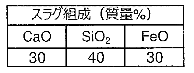
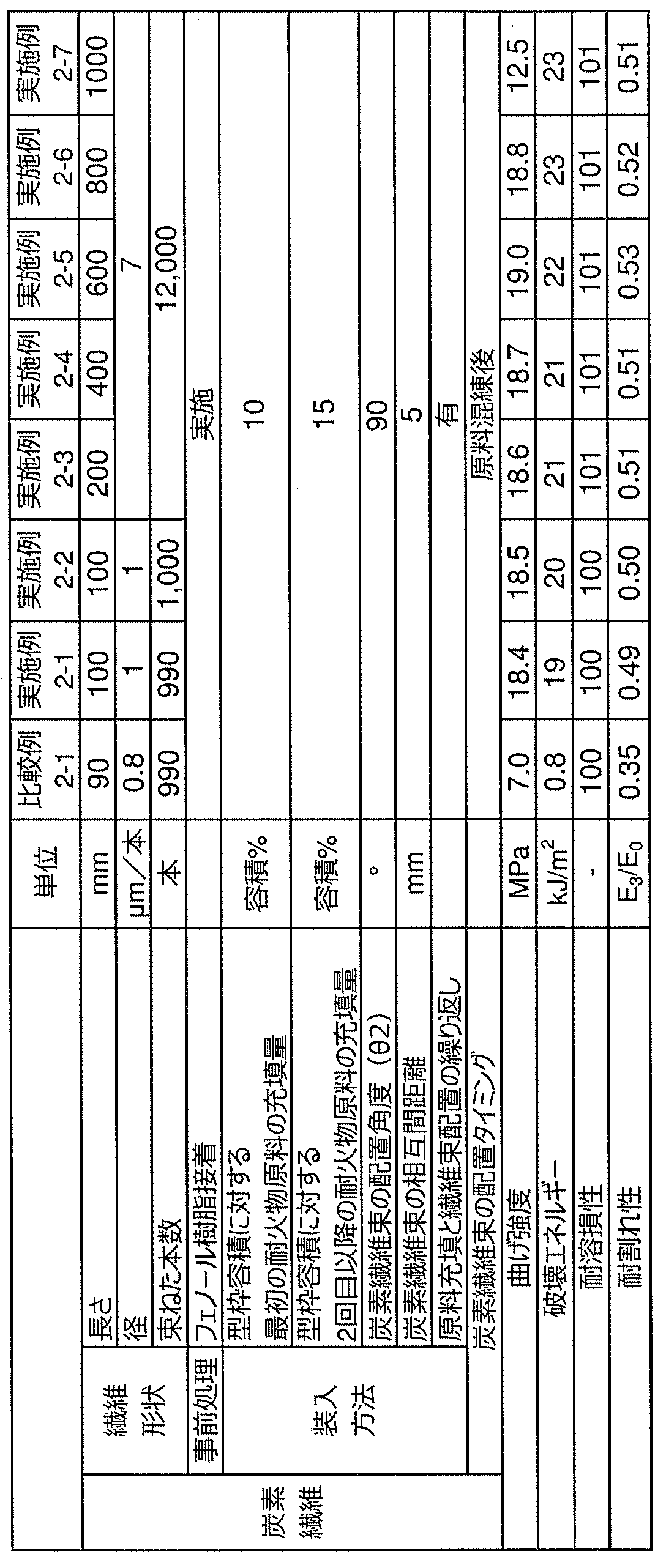
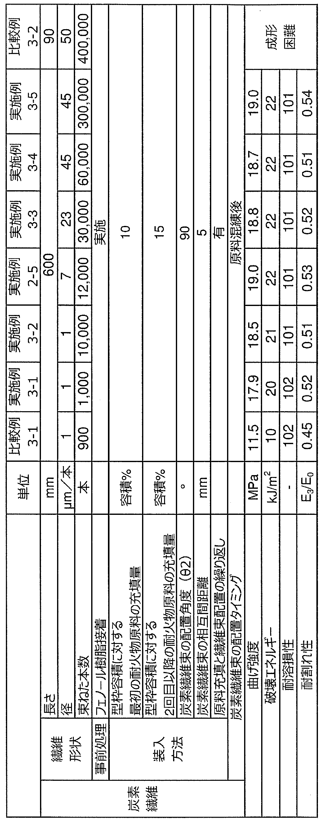
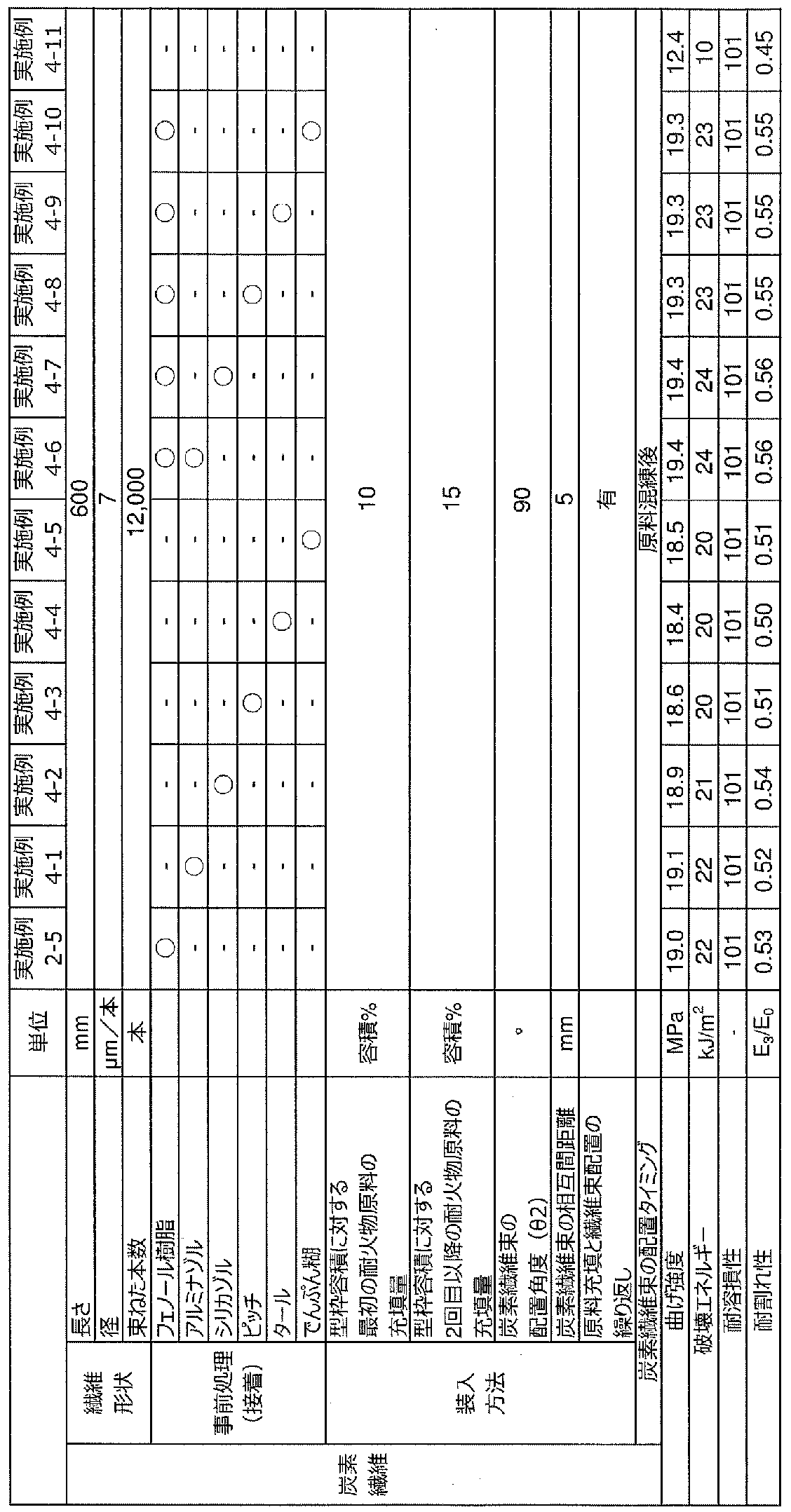
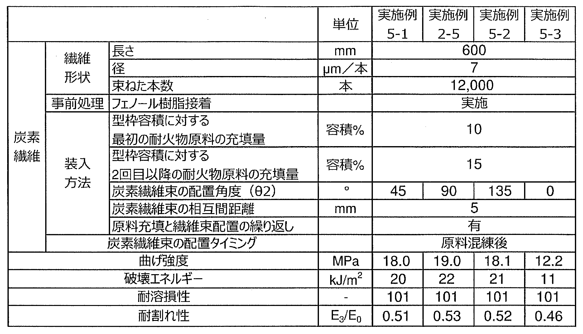
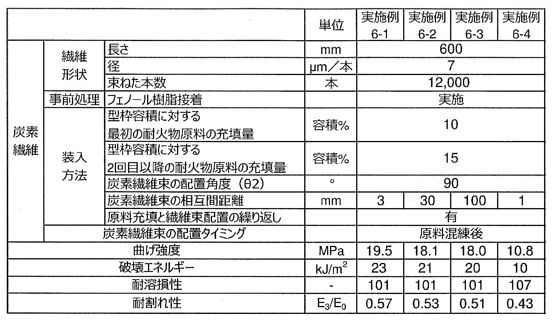
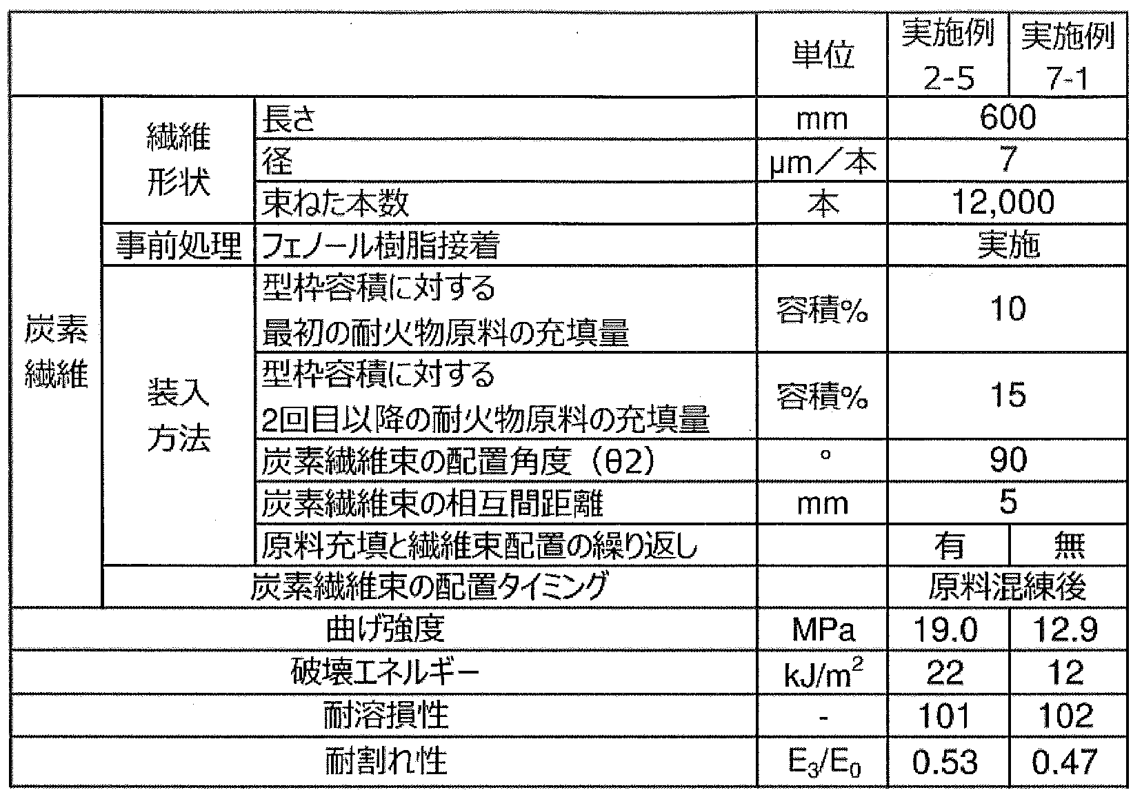
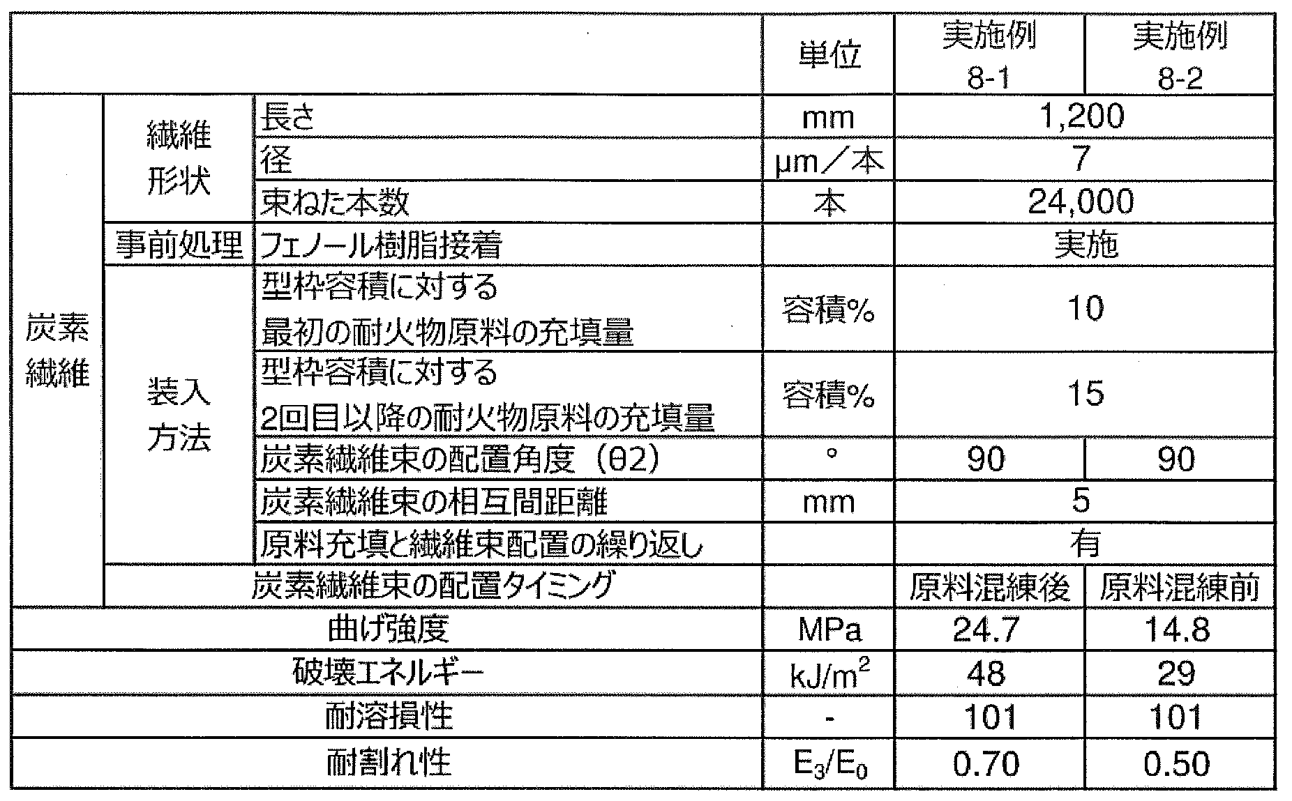
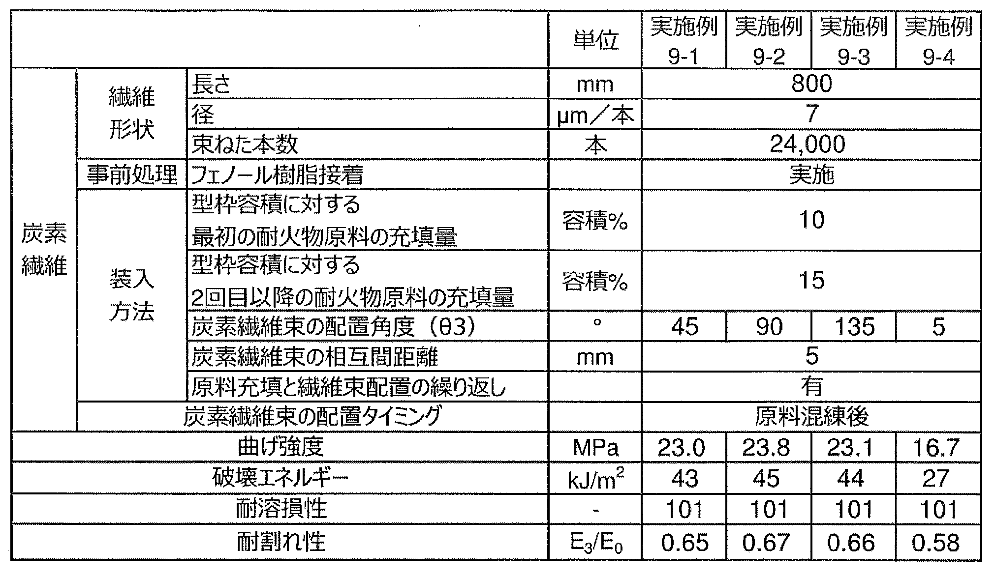
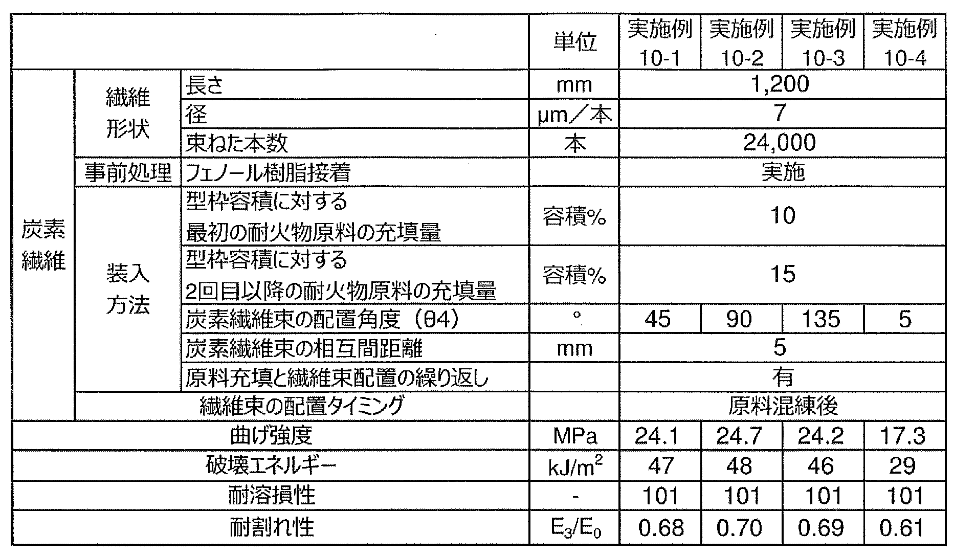

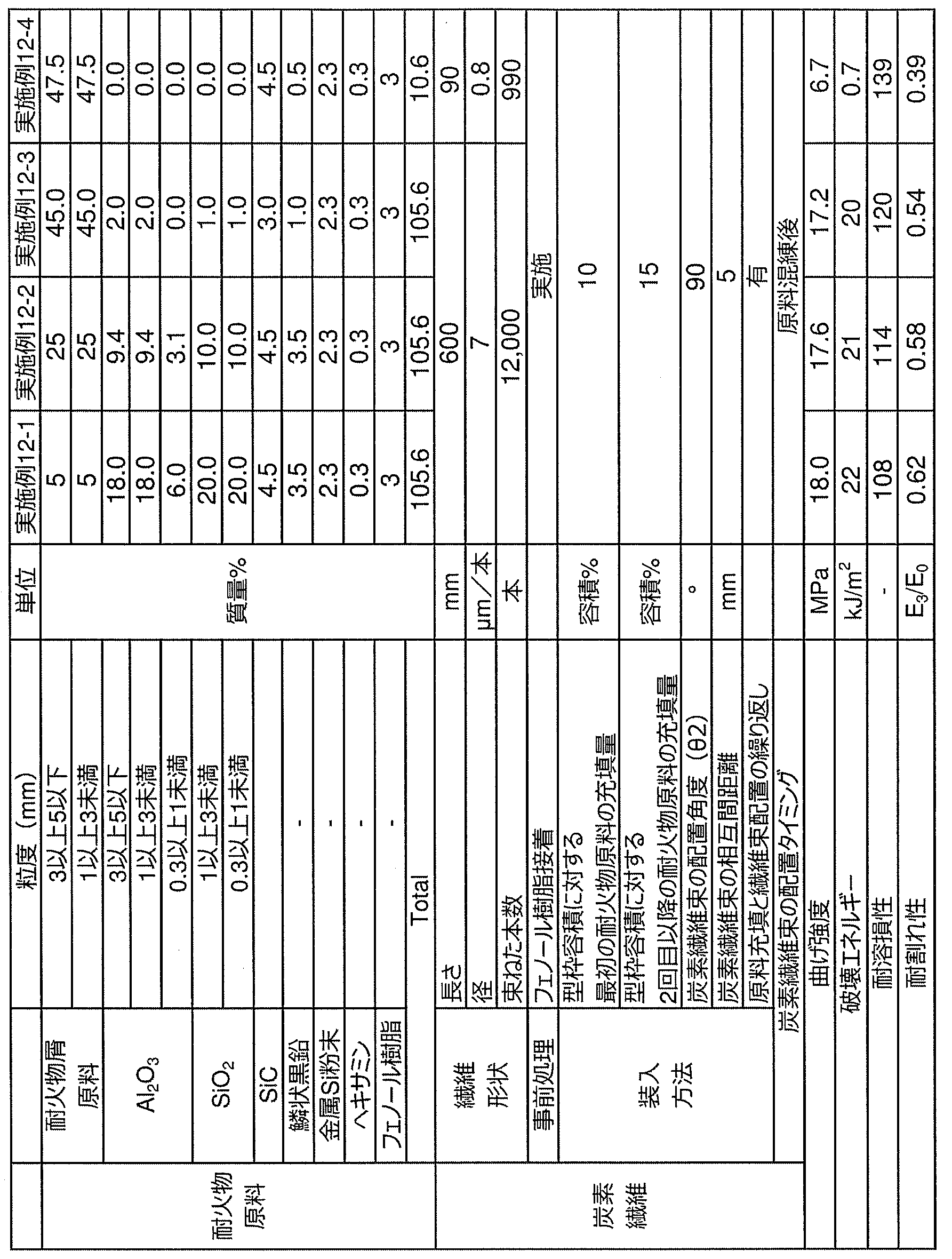

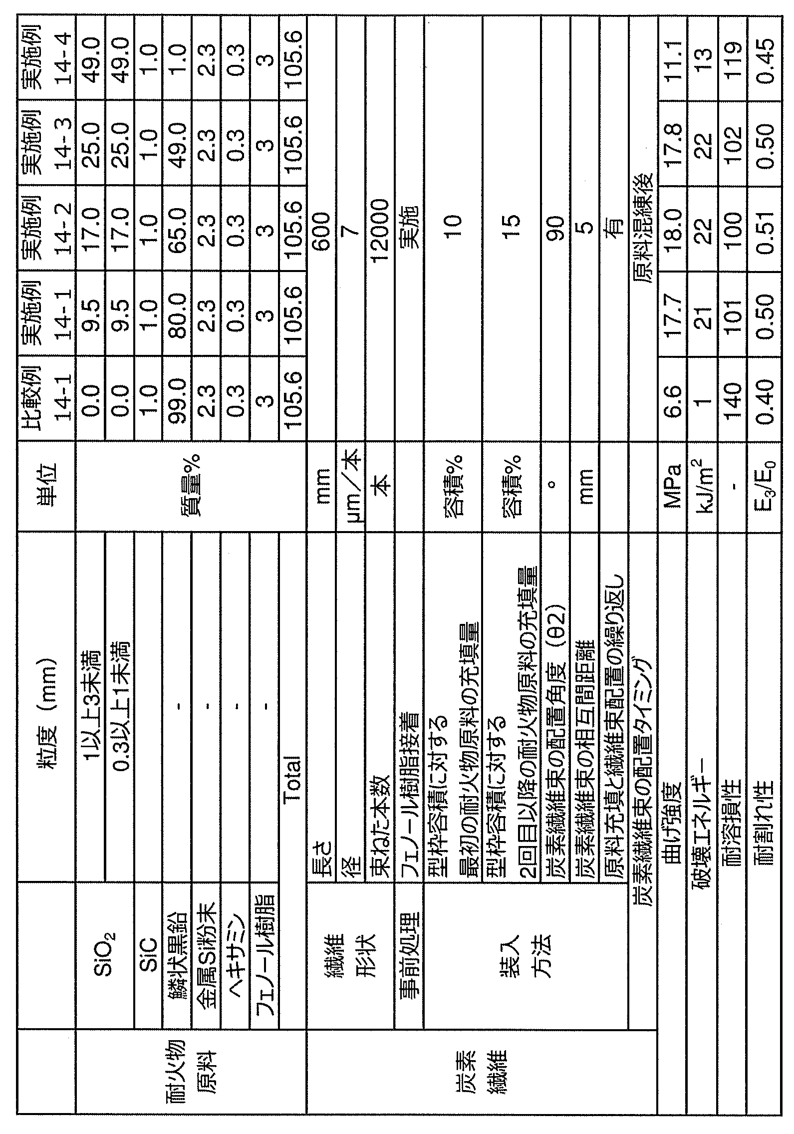
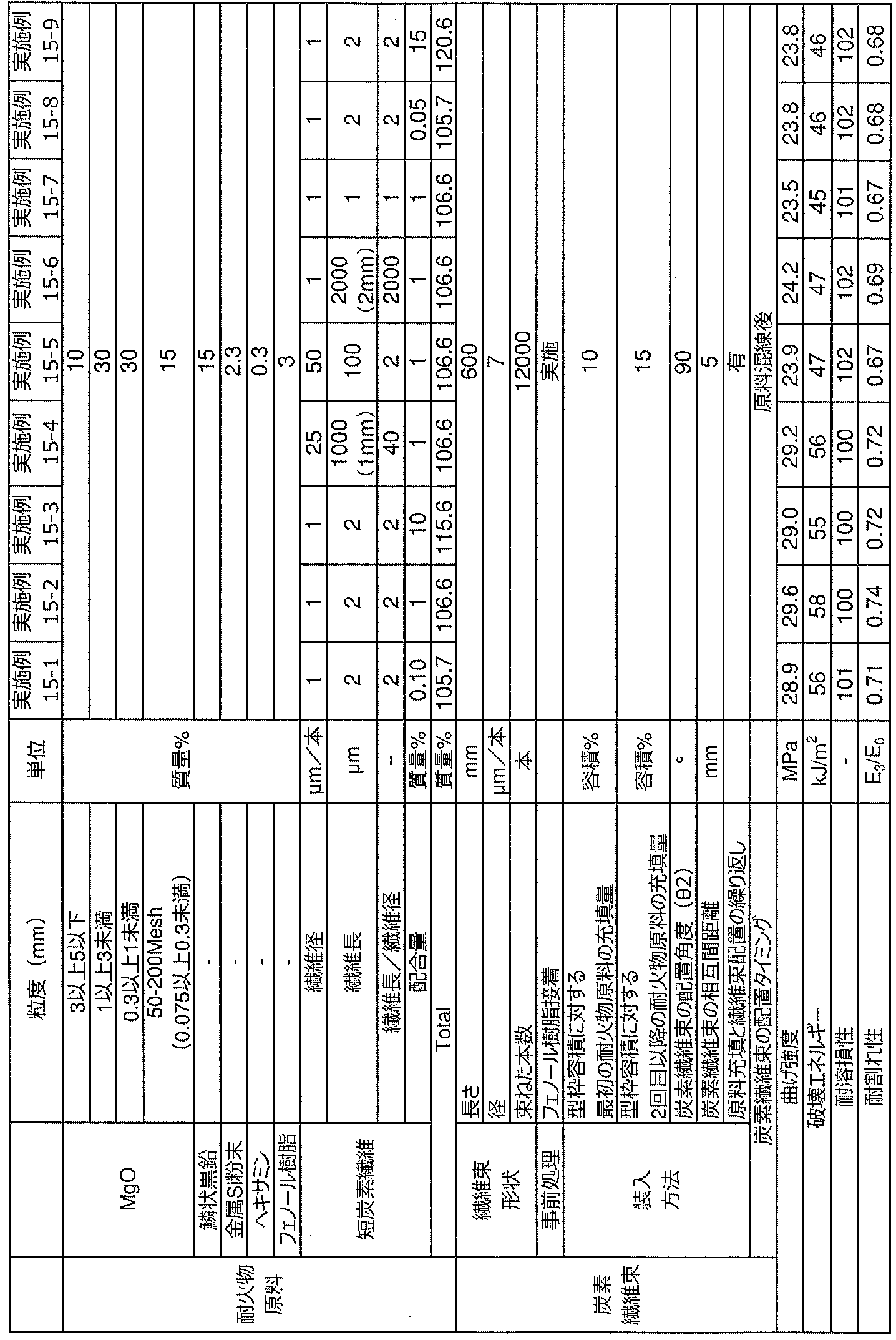
12 マグネシア・カーボン質原料
14 炭素繊維束
16 成形面
18 点線
20 矢印
30 支持部材
32 芯金
34 上支持盤
35 下支持盤
36 成形容器
38 CIP装置
40 圧力媒体
50 高周波誘導炉
52 誘導コイル
54 底板
56 溶銑
58 合成スラグ
60 黒鉛含有耐火物
Claims (21)
- 黒鉛の含有量が1質量%以上80質量%以下の範囲内である黒鉛含有耐火物であって、
長さが100mm以上の炭素繊維束が内部に配置され、
前記炭素繊維束は、繊維径が1μm/本以上45μm/本以下の範囲内である炭素繊維が1000本以上300000本以下の範囲内で束ねられて形成される、黒鉛含有耐火物。 - 前記炭素繊維は、1000本以上60000本以下の範囲内で束ねられる、請求項1に記載の黒鉛含有耐火物。
- 前記黒鉛含有耐火物は、マグネシア原料を20質量%以上99質量%以下の範囲内で含む、請求項1または請求項2に記載の黒鉛含有耐火物。
- 前記黒鉛含有耐火物は、アルミナ原料を10質量%以上95質量%以下の範囲内で含み、炭化珪素原料を1質量%以上含む、請求項1または請求項2に記載の黒鉛含有耐火物。
- 前記黒鉛含有耐火物は、さらにシリカ原料を1質量%以上50質量%以下の範囲内で含む、請求項4に記載の黒鉛含有耐火物。
- 前記黒鉛含有耐火物は、使用済み耐火物を粉砕した耐火物屑を10質量%以上90質量%以下の範囲内で含む、請求項1または請求項2に記載の黒鉛含有耐火物。
- 前記炭素繊維束は、フェノール樹脂、アルミナゾル、シリカゾル、ピッチおよびタールから選定される1種以上の接着剤を用いて接着される、請求項1から請求項6の何れか一項に記載の黒鉛含有耐火物。
- 前記炭素繊維束は、フェノール樹脂、エポキシ樹脂、メラミン樹脂、ユリア樹脂、アルキド樹脂、不飽和ポリエステル樹脂、ポリウレタン、熱硬化性ポリイミド、アルミナゾル、シリカゾル、ジルコニアゾル、クロミアゾル、チタニアゾル、マグネシアゾル、カルシアゾル、イットリアゾル、ピッチ、タールおよびでんぷん糊から選定される1種以上の接着剤を用いて接着される、請求項1から請求項6の何れか一項に記載の黒鉛含有耐火物。
- 前記黒鉛含有耐火物は、繊維径が1μm/本以上45μm/本以下であって、繊維長が1mm以下であり、繊維径に対する繊維長の比率(繊維長/繊維径)が2以上1000以下である短炭素繊維を、前記黒鉛含有耐火物に対して外掛けで0.10質量%以上10質量%以下の範囲内でさらに含む、請求項1から請求項8の何れか一項に記載の黒鉛含有耐火物。
- 黒鉛を1質量%以上80質量%以下の範囲内で含有し、内部に炭素繊維束が配置された黒鉛含有耐火物の製造方法であって、
炭素繊維を束ねて前記炭素繊維束にする束化工程と、
耐火物原料に黒鉛を配合して黒鉛含有耐火物原料にする配合工程と、
前記炭素繊維束が配置された前記黒鉛含有耐火物原料を成形して成形体にする成形工程と、
前記成形体を乾燥する乾燥工程と、
を有し、
前記束化工程では、繊維径が1μm/本以上45μm/本以下の範囲内である前記炭素繊維を、1000本以上300000本以下の範囲内で束ねて、長さ100mm以上の炭素繊維束とする、黒鉛含有耐火物の製造方法。 - 前記束化工程では、前記炭素繊維を1000本以上60000本以下の範囲内で束ねる、請求項10に記載の黒鉛含有耐火物の製造方法。
- 前記耐火物原料は、マグネシア原料であり、
前記配合工程では、前記マグネシア原料を20質量%以上99質量%以下の範囲内で配合する、請求項10または請求項11に記載の黒鉛含有耐火物の製造方法。 - 前記耐火物原料は、アルミナ原料および炭化珪素原料であり、
前記配合工程では、前記アルミナ原料を10質量%以上95質量%以下の範囲内で配合し、
前記炭化珪素原料を1質量%以上配合する、請求項10または請求項11に記載の黒鉛含有耐火物の製造方法。 - 前記耐火物原料は、アルミナ原料、炭化珪素原料およびシリカ原料であり、
前記配合工程では、アルミナ原料を10質量%以上95質量%以下の範囲内で配合し、
前記炭化珪素原料を1質量%以上配合し、
前記シリカ原料を1質量%以上50質量%以下の範囲内で配合する、請求項13に記載の黒鉛含有耐火物の製造方法。 - 前記耐火物原料は、使用済み耐火物を粉砕した耐火物屑であり、
前記配合工程では、前記耐火物屑を10質量%以上90質量%以下の範囲内で配合する請求項10または請求項11に記載の黒鉛含有耐火物の製造方法。 - 前記束化工程では、前記炭素繊維をフェノール樹脂、アルミナゾル、シリカゾル、ピッチおよびタールから選定される1種以上の接着剤を用いて接着する、請求項10から請求項15の何れか一項に記載の黒鉛含有耐火物の製造方法。
- 前記束化工程では、前記炭素繊維をフェノール樹脂、エポキシ樹脂、メラミン樹脂、ユリア樹脂、アルキド樹脂、不飽和ポリエステル樹脂、ポリウレタン、熱硬化性ポリイミド、アルミナゾル、シリカゾル、ジルコニアゾル、クロミアゾル、 チタニアゾル、マグネシアゾル、カルシアゾル、イットリアゾル、ピッチ、タールおよびでんぷん糊から選定される1種以上の接着剤を用いて接着する、請求項10から請求項15の何れか一項に記載の黒鉛含有耐火物の製造方法。
- 前記成形工程の前に、
前記黒鉛含有耐火物原料を混練する混練工程と、
前記黒鉛含有耐火物原料を成形する型枠に、混練された黒鉛含有耐火物原料と前記炭素繊維束とを充填する充填工程をさらに有する、請求項10から請求項17の何れか一項に記載の黒鉛含有耐火物の製造方法。 - 前記充填工程では、前記型枠の容積に対して5容積%以上の前記黒鉛含有耐火物原料を充填した後、相互間距離が3mm以上になるように前記炭素繊維束を並べて配置することを繰り返し、前記型枠に前記黒鉛含有耐火物原料と前記炭素繊維束とを充填する、請求項18に記載の黒鉛含有耐火物の製造方法。
- 前記成形工程の前に、
前記黒鉛含有耐火物原料を混練する混練工程と、
前記黒鉛含有耐火物原料を成形する成形容器に、混練された黒鉛含有耐火物原料と前記炭素繊維束とを充填する充填工程をさらに有し、
前記成形工程では、圧力媒体を介して前記成形容器に圧力を印加して成形体を成形する、請求項10から請求項17の何れか一項に記載の黒鉛含有耐火物の製造方法。 - 前記配合工程では、繊維径が1μm以上45μm以下であり、繊維長が1mm以下であり、繊維径に対する繊維長の比率(繊維長/繊維径)が2以上1000以下の範囲内である短炭素繊維を、前記黒鉛含有耐火物原料に対して外掛けで0.10質量%以上10質量%以下の範囲内で配合する、請求項10から請求項20の何れか一項に記載の黒鉛含有耐火物の製造方法。
Priority Applications (8)
| Application Number | Priority Date | Filing Date | Title |
|---|---|---|---|
| US16/487,248 US11156403B2 (en) | 2017-02-24 | 2018-02-01 | Graphite-containing refractory and method of producing graphite-containing refractory |
| KR1020197024278A KR102341900B1 (ko) | 2017-02-24 | 2018-02-01 | 흑연 함유 내화물 및 흑연 함유 내화물의 제조 방법 |
| JP2018516590A JP6593529B2 (ja) | 2017-02-24 | 2018-02-01 | 黒鉛含有耐火物および黒鉛含有耐火物の製造方法 |
| EP18757658.2A EP3587378B1 (en) | 2017-02-24 | 2018-02-01 | Graphite-containing refractory article and method for manufacturing graphite-containing refractory article |
| BR112019017208-4A BR112019017208B1 (pt) | 2017-02-24 | 2018-02-01 | Refratário que contém grafite e seu método de produção |
| RU2019126662A RU2730718C1 (ru) | 2017-02-24 | 2018-02-01 | Графитсодержащий огнеупорный материал и способ получения графитсодержащего огнеупорного материала |
| CN201880013645.5A CN110352183B (zh) | 2017-02-24 | 2018-02-01 | 含石墨的耐火物及含石墨的耐火物的制造方法 |
| US17/326,424 US11629916B2 (en) | 2017-02-24 | 2021-05-21 | Graphite-containing refractory and method of producing graphite-containing refractory |
Applications Claiming Priority (2)
| Application Number | Priority Date | Filing Date | Title |
|---|---|---|---|
| JP2017033126 | 2017-02-24 | ||
| JP2017-033126 | 2017-02-24 |
Related Child Applications (2)
| Application Number | Title | Priority Date | Filing Date |
|---|---|---|---|
| US16/487,248 A-371-Of-International US11156403B2 (en) | 2017-02-24 | 2018-02-01 | Graphite-containing refractory and method of producing graphite-containing refractory |
| US17/326,424 Division US11629916B2 (en) | 2017-02-24 | 2021-05-21 | Graphite-containing refractory and method of producing graphite-containing refractory |
Publications (1)
| Publication Number | Publication Date |
|---|---|
| WO2018155118A1 true WO2018155118A1 (ja) | 2018-08-30 |
Family
ID=63252730
Family Applications (1)
| Application Number | Title | Priority Date | Filing Date |
|---|---|---|---|
| PCT/JP2018/003333 Ceased WO2018155118A1 (ja) | 2017-02-24 | 2018-02-01 | 黒鉛含有耐火物および黒鉛含有耐火物の製造方法 |
Country Status (8)
| Country | Link |
|---|---|
| US (2) | US11156403B2 (ja) |
| EP (1) | EP3587378B1 (ja) |
| JP (1) | JP6593529B2 (ja) |
| KR (1) | KR102341900B1 (ja) |
| CN (1) | CN110352183B (ja) |
| RU (1) | RU2730718C1 (ja) |
| TW (1) | TWI691473B (ja) |
| WO (1) | WO2018155118A1 (ja) |
Cited By (9)
| Publication number | Priority date | Publication date | Assignee | Title |
|---|---|---|---|---|
| CN109748576A (zh) * | 2019-02-25 | 2019-05-14 | 长兴南冶冶金材料有限公司 | 一种高炉水冲沟陶瓷耐磨预制件 |
| JP2023089721A (ja) * | 2021-12-16 | 2023-06-28 | Jfeスチール株式会社 | 黒鉛含有耐火物およびその製造方法 |
| JP2023130033A (ja) * | 2022-03-07 | 2023-09-20 | Jfeスチール株式会社 | 黒鉛含有耐火物の製造方法 |
| JP2023130030A (ja) * | 2022-03-07 | 2023-09-20 | Jfeスチール株式会社 | 黒鉛含有耐火物、および黒鉛含有耐火物を備えた製鉄容器 |
| JP2023149344A (ja) * | 2022-03-31 | 2023-10-13 | Jfeスチール株式会社 | 黒鉛含有耐火物 |
| JP2023149350A (ja) * | 2022-03-31 | 2023-10-13 | Jfeスチール株式会社 | 黒鉛含有耐火物の製造方法 |
| JP2023166932A (ja) * | 2022-05-10 | 2023-11-22 | Jfeスチール株式会社 | 黒鉛含有耐火物 |
| JP2023166933A (ja) * | 2022-05-10 | 2023-11-22 | Jfeスチール株式会社 | 黒鉛含有耐火物の製造方法 |
| JP2024072595A (ja) * | 2022-11-16 | 2024-05-28 | Jfeスチール株式会社 | 溶融金属精錬容器の装入壁用耐火物の選定方法および溶融金属精錬容器 |
Families Citing this family (2)
| Publication number | Priority date | Publication date | Assignee | Title |
|---|---|---|---|---|
| US11156403B2 (en) * | 2017-02-24 | 2021-10-26 | Jfe Steel Corporation | Graphite-containing refractory and method of producing graphite-containing refractory |
| KR102475182B1 (ko) * | 2020-12-28 | 2022-12-06 | 이준영 | 차화기능을 갖는 복합섬유시트 |
Citations (5)
| Publication number | Priority date | Publication date | Assignee | Title |
|---|---|---|---|---|
| JPH07206535A (ja) * | 1993-12-29 | 1995-08-08 | Osaka Gas Co Ltd | 繊維補強耐火構造物およびその製造方法 |
| JPH08259311A (ja) * | 1995-03-28 | 1996-10-08 | Nippon Steel Corp | マグネシア−カーボン質耐火れんがの製造方法 |
| JP2005320196A (ja) | 2004-05-07 | 2005-11-17 | Nippon Steel Corp | 機械的強度および耐スポール性に優れる耐火物およびその製造方法 |
| JP2007106618A (ja) | 2005-10-12 | 2007-04-26 | Nippon Steel Corp | 繊維強化耐火物 |
| JP2013001606A (ja) * | 2011-06-17 | 2013-01-07 | Jfe Steel Corp | 使用済みマグネシアカーボンレンガの再利用方法およびマグネシアカーボンレンガの製造方法 |
Family Cites Families (15)
| Publication number | Priority date | Publication date | Assignee | Title |
|---|---|---|---|---|
| US5418063A (en) * | 1989-01-18 | 1995-05-23 | Loral Vought Systems Corporation | Carbon-carbon composite and method of making |
| US5439627A (en) | 1990-06-29 | 1995-08-08 | Flexline Services Ltd. | Process for manufacturing reinforced composites |
| US5177039A (en) * | 1990-12-06 | 1993-01-05 | Corning Incorporated | Method for making ceramic matrix composites |
| US5389716A (en) * | 1992-06-26 | 1995-02-14 | Georgia-Pacific Resins, Inc. | Fire resistant cured binder for fibrous mats |
| DE19711829C1 (de) * | 1997-03-21 | 1998-09-03 | Daimler Benz Ag | Verfahren zur Herstellung einer faserverstärkten Verbundkeramik |
| JP4452030B2 (ja) * | 2002-04-03 | 2010-04-21 | 新日本製鐵株式会社 | 無機繊維からなる棒状成形体で補強した耐火物とその製造方法 |
| US7297368B2 (en) | 2003-04-15 | 2007-11-20 | Ultramet | Method of making carbon fiber-carbon matrix reinforced ceramic composites |
| RU2337083C2 (ru) * | 2006-06-07 | 2008-10-27 | Общество с ограниченной ответственностью "Научно-производственная фирма "Кераком" (ООО "НПФ "Кераком") | Способ получения волокнисто-армированного углерод-карбидокремниевого композиционного материала |
| JP4206454B2 (ja) * | 2006-08-18 | 2009-01-14 | 福井県 | 多軸補強積層成型品及びその製造方法 |
| EP2080781A4 (en) * | 2006-11-09 | 2014-06-11 | Teijin Chemicals Ltd | COMPOSITE MATERIAL AND PROCESS FOR PRODUCING THE SAME |
| TWI396785B (zh) | 2009-06-10 | 2013-05-21 | Mitsubishi Rayon Co | 碳纖維用丙烯腈膨潤絲、前驅體纖維束、防焰纖維束、碳纖維束及它們的製造方法 |
| JP5944619B2 (ja) * | 2010-02-18 | 2016-07-05 | 日立化成株式会社 | 炭素繊維複合材、及びこの炭素繊維複合材を用いたブレーキ用部材、半導体用構造部材、耐熱性パネル、ヒートシンク |
| JP2011213519A (ja) | 2010-03-31 | 2011-10-27 | Kurosaki Harima Corp | 厚肉鱗状黒鉛含有耐火物 |
| KR101722041B1 (ko) | 2013-03-21 | 2017-04-03 | 구로사키 하리마 코포레이션 | 내화물 및 주조용 노즐 |
| US11156403B2 (en) * | 2017-02-24 | 2021-10-26 | Jfe Steel Corporation | Graphite-containing refractory and method of producing graphite-containing refractory |
-
2018
- 2018-02-01 US US16/487,248 patent/US11156403B2/en active Active
- 2018-02-01 JP JP2018516590A patent/JP6593529B2/ja active Active
- 2018-02-01 WO PCT/JP2018/003333 patent/WO2018155118A1/ja not_active Ceased
- 2018-02-01 EP EP18757658.2A patent/EP3587378B1/en active Active
- 2018-02-01 RU RU2019126662A patent/RU2730718C1/ru active
- 2018-02-01 KR KR1020197024278A patent/KR102341900B1/ko active Active
- 2018-02-01 CN CN201880013645.5A patent/CN110352183B/zh active Active
- 2018-02-12 TW TW107104966A patent/TWI691473B/zh active
-
2021
- 2021-05-21 US US17/326,424 patent/US11629916B2/en active Active
Patent Citations (5)
| Publication number | Priority date | Publication date | Assignee | Title |
|---|---|---|---|---|
| JPH07206535A (ja) * | 1993-12-29 | 1995-08-08 | Osaka Gas Co Ltd | 繊維補強耐火構造物およびその製造方法 |
| JPH08259311A (ja) * | 1995-03-28 | 1996-10-08 | Nippon Steel Corp | マグネシア−カーボン質耐火れんがの製造方法 |
| JP2005320196A (ja) | 2004-05-07 | 2005-11-17 | Nippon Steel Corp | 機械的強度および耐スポール性に優れる耐火物およびその製造方法 |
| JP2007106618A (ja) | 2005-10-12 | 2007-04-26 | Nippon Steel Corp | 繊維強化耐火物 |
| JP2013001606A (ja) * | 2011-06-17 | 2013-01-07 | Jfe Steel Corp | 使用済みマグネシアカーボンレンガの再利用方法およびマグネシアカーボンレンガの製造方法 |
Non-Patent Citations (1)
| Title |
|---|
| See also references of EP3587378A4 |
Cited By (17)
| Publication number | Priority date | Publication date | Assignee | Title |
|---|---|---|---|---|
| CN109748576A (zh) * | 2019-02-25 | 2019-05-14 | 长兴南冶冶金材料有限公司 | 一种高炉水冲沟陶瓷耐磨预制件 |
| JP7563370B2 (ja) | 2021-12-16 | 2024-10-08 | Jfeスチール株式会社 | 黒鉛含有耐火物およびその製造方法 |
| JP2023089721A (ja) * | 2021-12-16 | 2023-06-28 | Jfeスチール株式会社 | 黒鉛含有耐火物およびその製造方法 |
| JP2024152749A (ja) * | 2021-12-16 | 2024-10-25 | Jfeスチール株式会社 | 黒鉛含有耐火物およびその製造方法 |
| JP2023130033A (ja) * | 2022-03-07 | 2023-09-20 | Jfeスチール株式会社 | 黒鉛含有耐火物の製造方法 |
| JP2023130030A (ja) * | 2022-03-07 | 2023-09-20 | Jfeスチール株式会社 | 黒鉛含有耐火物、および黒鉛含有耐火物を備えた製鉄容器 |
| JP7619306B2 (ja) | 2022-03-07 | 2025-01-22 | Jfeスチール株式会社 | 黒鉛含有耐火物、および黒鉛含有耐火物を備えた製鉄容器 |
| JP7607605B2 (ja) | 2022-03-07 | 2024-12-27 | Jfeスチール株式会社 | 黒鉛含有耐火物の製造方法 |
| JP2023149344A (ja) * | 2022-03-31 | 2023-10-13 | Jfeスチール株式会社 | 黒鉛含有耐火物 |
| JP2023149350A (ja) * | 2022-03-31 | 2023-10-13 | Jfeスチール株式会社 | 黒鉛含有耐火物の製造方法 |
| JP7709125B2 (ja) | 2022-03-31 | 2025-07-16 | Jfeスチール株式会社 | 黒鉛含有耐火物の製造方法 |
| JP7709124B2 (ja) | 2022-03-31 | 2025-07-16 | Jfeスチール株式会社 | 黒鉛含有耐火物 |
| JP2023166933A (ja) * | 2022-05-10 | 2023-11-22 | Jfeスチール株式会社 | 黒鉛含有耐火物の製造方法 |
| JP2023166932A (ja) * | 2022-05-10 | 2023-11-22 | Jfeスチール株式会社 | 黒鉛含有耐火物 |
| JP7704066B2 (ja) | 2022-05-10 | 2025-07-08 | Jfeスチール株式会社 | 黒鉛含有耐火物 |
| JP2024072595A (ja) * | 2022-11-16 | 2024-05-28 | Jfeスチール株式会社 | 溶融金属精錬容器の装入壁用耐火物の選定方法および溶融金属精錬容器 |
| JP7732146B2 (ja) | 2022-11-16 | 2025-09-02 | Jfeスチール株式会社 | 溶融金属精錬容器の装入壁用耐火物の選定方法および溶融金属精錬容器 |
Also Published As
| Publication number | Publication date |
|---|---|
| US20190368815A1 (en) | 2019-12-05 |
| JPWO2018155118A1 (ja) | 2019-03-07 |
| JP6593529B2 (ja) | 2019-10-23 |
| EP3587378A1 (en) | 2020-01-01 |
| KR102341900B1 (ko) | 2021-12-21 |
| BR112019017208A2 (pt) | 2020-04-14 |
| EP3587378A4 (en) | 2020-01-15 |
| US11629916B2 (en) | 2023-04-18 |
| KR20190105238A (ko) | 2019-09-16 |
| US20210270529A1 (en) | 2021-09-02 |
| CN110352183A (zh) | 2019-10-18 |
| TW201835005A (zh) | 2018-10-01 |
| TWI691473B (zh) | 2020-04-21 |
| EP3587378B1 (en) | 2024-06-05 |
| RU2730718C1 (ru) | 2020-08-25 |
| US11156403B2 (en) | 2021-10-26 |
| CN110352183B (zh) | 2022-03-25 |
Similar Documents
| Publication | Publication Date | Title |
|---|---|---|
| JP6593529B2 (ja) | 黒鉛含有耐火物および黒鉛含有耐火物の製造方法 | |
| JP6631611B2 (ja) | マグネシア・カーボン質耐火物及びマグネシア・カーボン質耐火物の製造方法 | |
| JP6957544B2 (ja) | 黒鉛含有耐火物の製造方法 | |
| JP7607605B2 (ja) | 黒鉛含有耐火物の製造方法 | |
| JP6974801B2 (ja) | 黒鉛含有耐火物 | |
| JP7709124B2 (ja) | 黒鉛含有耐火物 | |
| JP7704066B2 (ja) | 黒鉛含有耐火物 | |
| JP4945257B2 (ja) | 耐火物 | |
| JP7709125B2 (ja) | 黒鉛含有耐火物の製造方法 | |
| JP7563370B2 (ja) | 黒鉛含有耐火物およびその製造方法 | |
| JP7619306B2 (ja) | 黒鉛含有耐火物、および黒鉛含有耐火物を備えた製鉄容器 | |
| JP2022074684A (ja) | 炭素含有耐火物 | |
| JP2023166933A (ja) | 黒鉛含有耐火物の製造方法 | |
| JP6375555B2 (ja) | マグネシア・カーボンれんがの製造方法 | |
| JP5556043B2 (ja) | 耐スポーリング性に優れた耐火物及びその製造方法 | |
| JP2005231953A (ja) | 黒鉛含有煉瓦 | |
| KR101370635B1 (ko) | 철강용 내화물 | |
| JP2006089321A (ja) | 流し込み耐火材 | |
| JP2006021980A (ja) | 流し込み耐火材 | |
| JPH06107469A (ja) | 鋳造用耐火物の製造方法 |
Legal Events
| Date | Code | Title | Description |
|---|---|---|---|
| ENP | Entry into the national phase |
Ref document number: 2018516590 Country of ref document: JP Kind code of ref document: A |
|
| 121 | Ep: the epo has been informed by wipo that ep was designated in this application |
Ref document number: 18757658 Country of ref document: EP Kind code of ref document: A1 |
|
| ENP | Entry into the national phase |
Ref document number: 20197024278 Country of ref document: KR Kind code of ref document: A |
|
| NENP | Non-entry into the national phase |
Ref country code: DE |
|
| REG | Reference to national code |
Ref country code: BR Ref legal event code: B01A Ref document number: 112019017208 Country of ref document: BR |
|
| ENP | Entry into the national phase |
Ref document number: 2018757658 Country of ref document: EP Effective date: 20190924 |
|
| ENP | Entry into the national phase |
Ref document number: 112019017208 Country of ref document: BR Kind code of ref document: A2 Effective date: 20190819 |