WO2018155176A1 - 車両用灯具 - Google Patents
車両用灯具 Download PDFInfo
- Publication number
- WO2018155176A1 WO2018155176A1 PCT/JP2018/004092 JP2018004092W WO2018155176A1 WO 2018155176 A1 WO2018155176 A1 WO 2018155176A1 JP 2018004092 W JP2018004092 W JP 2018004092W WO 2018155176 A1 WO2018155176 A1 WO 2018155176A1
- Authority
- WO
- WIPO (PCT)
- Prior art keywords
- heat
- light source
- base
- air
- heat radiating
- Prior art date
- Legal status (The legal status is an assumption and is not a legal conclusion. Google has not performed a legal analysis and makes no representation as to the accuracy of the status listed.)
- Ceased
Links
Images



Classifications
-
- F—MECHANICAL ENGINEERING; LIGHTING; HEATING; WEAPONS; BLASTING
- F21—LIGHTING
- F21S—NON-PORTABLE LIGHTING DEVICES; SYSTEMS THEREOF; VEHICLE LIGHTING DEVICES SPECIALLY ADAPTED FOR VEHICLE EXTERIORS
- F21S45/00—Arrangements within vehicle lighting devices specially adapted for vehicle exteriors, for purposes other than emission or distribution of light
- F21S45/60—Heating of lighting devices, e.g. for demisting
-
- F—MECHANICAL ENGINEERING; LIGHTING; HEATING; WEAPONS; BLASTING
- F21—LIGHTING
- F21S—NON-PORTABLE LIGHTING DEVICES; SYSTEMS THEREOF; VEHICLE LIGHTING DEVICES SPECIALLY ADAPTED FOR VEHICLE EXTERIORS
- F21S45/00—Arrangements within vehicle lighting devices specially adapted for vehicle exteriors, for purposes other than emission or distribution of light
- F21S45/40—Cooling of lighting devices
- F21S45/42—Forced cooling
- F21S45/43—Forced cooling using gas
-
- F—MECHANICAL ENGINEERING; LIGHTING; HEATING; WEAPONS; BLASTING
- F21—LIGHTING
- F21S—NON-PORTABLE LIGHTING DEVICES; SYSTEMS THEREOF; VEHICLE LIGHTING DEVICES SPECIALLY ADAPTED FOR VEHICLE EXTERIORS
- F21S41/00—Illuminating devices specially adapted for vehicle exteriors, e.g. headlamps
- F21S41/10—Illuminating devices specially adapted for vehicle exteriors, e.g. headlamps characterised by the light source
- F21S41/14—Illuminating devices specially adapted for vehicle exteriors, e.g. headlamps characterised by the light source characterised by the type of light source
- F21S41/141—Light emitting diodes [LED]
- F21S41/143—Light emitting diodes [LED] the main emission direction of the LED being parallel to the optical axis of the illuminating device
-
- F—MECHANICAL ENGINEERING; LIGHTING; HEATING; WEAPONS; BLASTING
- F21—LIGHTING
- F21S—NON-PORTABLE LIGHTING DEVICES; SYSTEMS THEREOF; VEHICLE LIGHTING DEVICES SPECIALLY ADAPTED FOR VEHICLE EXTERIORS
- F21S41/00—Illuminating devices specially adapted for vehicle exteriors, e.g. headlamps
- F21S41/10—Illuminating devices specially adapted for vehicle exteriors, e.g. headlamps characterised by the light source
- F21S41/19—Attachment of light sources or lamp holders
- F21S41/192—Details of lamp holders, terminals or connectors
-
- F—MECHANICAL ENGINEERING; LIGHTING; HEATING; WEAPONS; BLASTING
- F21—LIGHTING
- F21S—NON-PORTABLE LIGHTING DEVICES; SYSTEMS THEREOF; VEHICLE LIGHTING DEVICES SPECIALLY ADAPTED FOR VEHICLE EXTERIORS
- F21S45/00—Arrangements within vehicle lighting devices specially adapted for vehicle exteriors, for purposes other than emission or distribution of light
- F21S45/20—Promoting gas flow in lighting devices, e.g. directing flow toward the cover glass for demisting
-
- F—MECHANICAL ENGINEERING; LIGHTING; HEATING; WEAPONS; BLASTING
- F21—LIGHTING
- F21S—NON-PORTABLE LIGHTING DEVICES; SYSTEMS THEREOF; VEHICLE LIGHTING DEVICES SPECIALLY ADAPTED FOR VEHICLE EXTERIORS
- F21S45/00—Arrangements within vehicle lighting devices specially adapted for vehicle exteriors, for purposes other than emission or distribution of light
- F21S45/40—Cooling of lighting devices
- F21S45/47—Passive cooling, e.g. using fins, thermal conductive elements or openings
-
- F—MECHANICAL ENGINEERING; LIGHTING; HEATING; WEAPONS; BLASTING
- F21—LIGHTING
- F21S—NON-PORTABLE LIGHTING DEVICES; SYSTEMS THEREOF; VEHICLE LIGHTING DEVICES SPECIALLY ADAPTED FOR VEHICLE EXTERIORS
- F21S45/00—Arrangements within vehicle lighting devices specially adapted for vehicle exteriors, for purposes other than emission or distribution of light
- F21S45/40—Cooling of lighting devices
- F21S45/49—Attachment of the cooling means
Definitions
- the technology disclosed here relates to a vehicular lamp.
- Patent Document 1 a vehicular lamp in which a heat sink and a blower are provided behind a light source is known.
- this type of vehicle lamp is provided with a heat sink to dissipate heat from the light source, and cools the heat sink by blowing air from the blower toward the heat sink. That is, the heat sink and the air blower provided in the conventional vehicle lamp are used exclusively for radiating the heat from the light source, and do not effectively use the radiated heat.
- Some vehicle lamps such as headlights, require the outer lens to have clouding clearing due to condensation or snow melting performance, and dedicated heaters, thermocouples, and wiring for these requirements.
- there is no room for improvement in efficient clouding and snow melting of the outer lens because there is no one that efficiently uses the heat from the light source. .
- the technology disclosed here achieves an efficient overcasting and snow melting effect of the outer lens.
- the technology disclosed herein includes a light source, an outer lens disposed in front of the light source, a heat sink thermally connected to the light source, and a blower device provided with a blower on the back of the light source. It is related with the vehicle lamp provided with.
- the heat sink extends in the front-rear direction from a base portion extending outward in a direction intersecting the optical axis extending forward of the light source with respect to the light source, and blown from the blower portion. And a heat dissipating part that directs air to the outer lens while dissipating heat to the air.
- the air is blown from the blower so that the air is directed to the outer lens along the heat dissipating part extending in the front-rear direction from the outer portion in the cross direction of the base, thereby promoting heat dissipation of the heat sink.
- the air blown using the air can reach the outer lens while warming.
- the heat dissipation of the outer lens can be used to obtain an efficient clouding clearing and snow melting effect of the outer lens.
- the front indicates the irradiation direction of the light source
- the back indicates the opposite direction to the irradiation direction
- the front-rear direction indicates a direction parallel to the optical axis of the light source.
- the light source may be provided in front of the base, and may be provided in the center of the base in a front view.
- the base when the light source is transmitted to the outer side in the cross direction by the base, compared to the case where the light source is provided in a portion that is biased outward in the cross direction with respect to the center of the base, the base Can be transmitted evenly in the circumferential direction, and heat can be radiated more efficiently.
- the heat radiating portion may be extended until the front end thereof is positioned in front of the light source.
- the heat radiating portion extends forward from the light source, the heat storage property and heat radiating property of the heat transmitted from the base portion can be improved. Can increase the warming ability of the air.
- the heat radiating part extends forward from the light source, the space in the limited lamp room, that is, the front and rear length between the outer lens and the light source can be effectively utilized, and the surface area of the heat radiating part can be reduced. Can be increased to improve heat dissipation.
- the distance between the heat source and the outer lens disposed in front of the heat source is usually set in consideration of optical viewpoints, etc., but the light source corresponding to this distance can be provided by extending the heat radiating portion ahead of the light source.
- the front space can be used effectively.
- the heat radiating portion may be provided longer than the front of the base portion.
- the heat radiating portion As long as possible in the front-rear direction.
- the heat radiating portion due to the layout relationship with the outer lens arranged in front of the base portion, the heat radiating portion The length of the part extending forward is limited.
- the heat dissipating part can be extended to the back without receiving such a restriction, and the heat dissipating property can be further improved.
- the heat radiating portion includes a heat radiating portion main body provided in the circumferential direction with the light source as a central portion, and extends from the heat radiating portion main body outward in the cross direction and extends in the front-rear direction and in the circumferential direction. It is good also as what was comprised with the arrange
- the surface area of the heat radiating portion can be enlarged and the heat radiating property can be enhanced.
- the air guide part is formed by the heat radiating fin, the air blown from the air blowing part can be guided along the air guide part while being guided by the heat radiating fin. Can be oriented.
- the heat dissipating fins may be provided with a protruding length longer than the thickness of the base.
- the heat radiating section is provided with a plurality of heat radiating fins, the surface area of the heat radiating section can be dramatically increased by increasing the length of each protrusion, thereby improving the heat dissipation. Can do.
- the radiating fin is provided with a protruding length longer than the thickness of the base portion, the air guiding (guide) function by the radiating fin of the air blown from the air blowing portion in the air guiding portion can be enhanced.
- the air blowing device may be configured to jet from the air blowing unit provided at a portion corresponding to the air guiding unit in the circumferential direction of the heat radiating unit.
- the air jetted from the blower can be efficiently blown along the air guide, the directivity to the outer lens can be improved.
- the heat dissipation of the outer lens and the effect of melting snow can be obtained by using the heat radiation of the light source.
- FIG. 3 is an enlarged sectional view taken along line AA in FIG. 2.
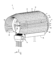
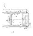
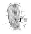
- FIG. 1 is a partial vertical cross-sectional view of the vehicle lamp of the present embodiment in the center in the vehicle width direction, and is a cross-sectional view of the vehicle lamp of the present embodiment corresponding to the arrow BB in FIG. 2 is a perspective view of a main part of the vehicular lamp according to the present embodiment
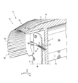
- FIG. 3 is a perspective cross-sectional view of a vertical section at the center of the vehicular lamp according to the present embodiment in the vehicle width direction.
- 4 is a perspective sectional view taken along line B
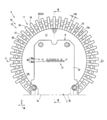
- FIG. 4 is a front view of the main part of the vehicle lamp of the present embodiment
- FIG. 5 is a sectional view taken along the line CC in FIG. 4
- FIG. FIG. 6B is an enlarged cross-sectional view taken along line AA in FIG.
- the vehicular lamps 1 and 1 according to the present embodiment are used as fog lamps arranged on the left and right of the front part of the vehicle, and the basic configuration is the same on the left and right. Only 1 will be described.
- arrow F indicates the front of the vehicle
- arrow W indicates the vehicle width direction
- arrow U indicates the vehicle upper direction.
- the irradiation direction of the LED as the light source provided in the vehicular lamp 1 coincides with the front of the vehicle.
- a vehicular lamp 1 according to the present embodiment includes a concave lamp housing (not shown) that opens forward, and a transparent outer lens 2 that covers the front opening as shown in FIG.
- An internal space defined by the lamp housing and the outer lens 2 is formed as a lamp chamber 3.
- a lamp unit 4 is disposed in the lamp chamber 3 as shown in FIG. As shown in FIGS. 2 and 3, the lamp unit 4 includes an LED 5 as a light source, a flat copper substrate 6 on which the LED 5 is mounted, a heat sink 10 thermally connected to the LED 5, and a blower unit. And a blower device 20 provided with a blower opening 27 (see FIG. 2).
- the substrate 6 is disposed so as to be orthogonal to the front-rear direction (that is, facing the outer lens 2), and as shown in FIG. 4, the front surface of the front surface 6f of the substrate 6 (that is, viewed from the outer lens 2 side) is the center.
- the part is provided with a plurality of LEDs 5 in order to widen the irradiation range, and all of them are attached so as to face forward (that is, the optical axis X of the LEDs 5 coincides with the front-rear direction).
- the plurality of LEDs 5 are arranged in a row extending in the vehicle width direction, and the light source array unit 30 (30u, 30d) is configured by these LEDs 5.
- the number and arrangement of the LEDs 5 are appropriately set according to the luminance required for the vehicular lamp 1, and in this example, two light source array portions 30 are mounted on the front surface of the substrate 6 in parallel with each other on the upper and lower sides.
- the LED module 31 is formed by these two light source array sections 30. Among these, nine LEDs 5 are provided in the upper light source array section 30u, and twelve LEDs 5 are respectively provided in the lower light source array section 30d.
- the arrangement pattern is arranged as follows.
- the heat sink 10 is formed of aluminum or an aluminum alloy, and is disposed behind the LED module 31 and extends radially outward with respect to the LED module 31, and the radial direction of the base 11 (that is, the optical axis X). And the heat dissipating part 12 provided in the outer portion in the direction intersecting with.
- the substrate 6 is attached to the base 11 as an adhesive having thermal conductivity, for example, by being attached to the front surface of the base 11 with Si-based conductive grease 8 (see FIG. 3). As a result, the base 11 exchanges heat with the substrate 6 to dissipate the heat of the LED 5 and to conduct heat to the heat dissipating part 12.
- the blower 20 is provided behind the base 11, and the blower opening 27 is provided behind the radiator 12.
- the heat dissipating part 12 is provided over the entire circumference except for the lower part of the heat sink 10 at least in the radial direction outside the LED module 31 of the base part 11.
- the heat radiating portion 12 is formed in a substantially C shape in a front view in which a cylindrical lower portion extending substantially in the front-rear direction is opened downward (see FIG. 4).
- the lower opening 7 that opens toward the lower side of the heat radiating portion 12 is formed over the entire length of the heat radiating portion 12 in the front-rear direction.
- the portions corresponding to the peripheral edges 7 a and 7 b in the circumferential direction of the heat radiating portion 12 are formed to protrude downward. That is, one opening edge portion 7a protruding downward is formed at one edge portion in the circumferential direction of the heat radiating portion 12, and the other opening edge portion 7b is formed at the other edge portion. (See the figure).
- the heat dissipating part 12 includes a front extending part 13 that extends forward to the front of the outer lens 2 with respect to the base part 11, and a rear extending part 14 that extends rearward. It has.
- the front extending portion 13 is extended so that the front end 12t is positioned in front of the LED 5.
- the front extension part 13 is arrange
- the rear extending portion 14 is extended with a longer front and rear length than the front extending portion 13.
- the rear extension 14 and the base 11 define a heat sink internal space 10A that opens rearward and downward in the radial inner side of the rear extension 14 and on the back of the base 11.
- the heat dissipating part 12 includes a heat dissipating part main body 15 located on the radially inner side and a plurality of standing up radially outward from the heat dissipating part main body 15.
- the heat radiating fins 16 are integrally formed.
- the heat radiating part main body 15 has the same thickness (plate thickness) in the circumferential direction of the heat radiating part 12 and is continuously formed (see FIG. 5).
- the heat dissipating part main body 15 is formed continuously in the front-rear direction at portions corresponding to the rear part of the front extending part 13, the base part 11, and the rear extending part 14 in the front-rear direction of the heat dissipating part 12.
- the heat radiating fins 16 extend linearly in the front-rear direction on the outer peripheral surface of the heat radiating portion main body 15 and are arranged at equal pitches in the circumferential direction.
- the heat radiating fins 16 correspond not only to the portion corresponding to the heat radiating portion main body 15 provided in the rear portion in the front-rear direction of the front extending portion 13 but also to the heat radiating portion main body 15. It extends forward from the site to the front end 12t of the forward extension 13. That is, the radiating fins 16 are continuously formed with the same thickness (t16) over the entire length of the radiating portion 12 in the front-rear direction.
- the radiation fin main body 15 is not provided between the heat radiation fins 16 and 16 in front of the heat radiation part main body 15 of the front extension part 13, it communicates in the radial direction (see FIGS. 3 and 5). ).
- the radiation fin 16 provided in the front extension part 13 is formed so that the radial thickness is gradually reduced so as to taper forward.
- the radiation fins 16 provided in the rear extension 14 are provided with a protruding length (radial length) (h16) longer than the thickness (plate thickness) (t11) of the base 11. ing.
- the base 11 is formed thicker than each of the heat radiating body 15 and the heat radiating fins 16 (t11> t15, t16), but the thickness of the base 11 ( t11) is provided so as to be less than twice the plate thicknesses (t15, t16) of the heat dissipating part main body 15 and the heat dissipating fins 16.
- the heat radiating part 12 extends in the front-rear direction so as to be directed to the outer lens 2 while radiating heat to the air blown from the blower opening 27.
- an air guide path 17 extending linearly in the front-rear direction from the front end 12t to the rear end is provided between the adjacent heat dissipating fins 16, 16 in the circumferential direction of the heat dissipating portion 12. It is configured.
- This air guide path 17 is a flow path in which both side walls are formed by adjacent heat radiating fins 16 so as to direct wind (air) jetted from a blower opening 27 described later to the front outer lens 2 side.
- the air guide path 17 has a heat dissipating body 15 in the front-rear direction of the heat dissipating part 12, and heat dissipating fins 16, 16 adjacent in the circumferential direction, and a radially outer surface 15 a of the heat dissipating part main body 15 positioned therebetween Thus, it is formed in a concave shape that is recessed radially inward with respect to the tips of the heat radiation fins 16 when viewed in the orthogonal direction of the front-rear direction.
- the blower 20 is mounted on the heat sink 10 in a state of being fitted into the heat sink internal space 10A from the rear opening of the heat sink internal space 10A, as shown in FIG.
- the piezo fan unit 21 and a housing 22 in which the piezo fan unit 21 is accommodated are shown in FIGS. 1, 2, and 5.
- the housing 22 includes a housing 23 and a back cover 24.
- the housing 23 is fitted into the heat sink internal space 10A, and has a bottomed cylindrical shape having an internal space 23A in which the front surface 23f is closed and the rear is open. Has been.
- the back cover 24 is formed in a bottomed cylindrical shape having a shallower bottom than the housing 23 having an inner space 24A having a rear surface 24r closed and a front opening. An opening is formed in the center of the front surface 24f of the back cover 24.
- the internal space 23 ⁇ / b> A of the housing 23 and the internal space 24 ⁇ / b> A of the back cover 24 communicate with each other in the front-rear direction to form an internal space 22 ⁇ / b> A of the housing 22.
- a flange portion 25 is provided at the outer peripheral portion of the back cover 24, in which the entire circumferential direction protrudes radially outward from the outer diameter of the housing 23 so that the rear end surface 10r of the heat sink 10 can be engaged from behind.
- the annular front surface 25 a of the flange portion 25 is formed by a radial side portion with respect to an opening provided in the center portion of the front surface 24 f of the back cover 24.
- a plurality of ventilation openings 27 that are opened rearward are provided in the circumferential direction so as to communicate the internal space 22 ⁇ / b> A of the housing 22 and the outside of the housing 22.
- the plurality of ventilation openings 27 correspond to portions corresponding to the air guide path 17 in the circumferential direction of the heat radiating portion 12 (that is, between adjacent heat radiating fins 16, 16). The air blown from the piezo fan unit 21 disposed in the housing 22 is jetted from the blower opening 27.
- a bolt insertion hole 25c is formed at a predetermined portion in the circumferential direction of the flange portion 25 of the back cover 24, and the bolt insertion in the circumferential direction of the rear end surface 10r of the heat sink 10 is performed.
- a bolt insertion hole 10c is also formed in a portion corresponding to the hole 25c, and the blower 20 is attached using a bolt B1 or the like with the flange portion 25 engaged with the rear end surface 10r of the heat sink 10.
- the piezo fan unit 21 is a known fan that generates wind by utilizing the reverse voltage effect of the piezo. Although not shown, a piezo (piezoelectric element) and a blade shape connected to the piezo in a cantilever manner. And an AC voltage applying means for exciting the air blowing plate by applying an AC voltage to the piezo and vibrating the front end (free end) of the air blowing plate in the thickness direction. .
- the piezo fan unit 21 is installed in the internal space 22 ⁇ / b> A of the housing 22 so as to generate wind toward the rear by vibration of the blower plate.
- the air blower 20 flows inside the housing 22 so that the air blown from the piezo fan unit 21 once hits the rear surface 24r of the back cover 24 and then circulates radially outward (flange portion 25 side). In this configuration, the air is blown from the blower opening 27.
- the lamp unit 4 described above is attached to a lamp unit base portion 100 provided at the bottom of the lamp housing 23 via an inner bracket 40 as a component connecting member.
- Reference numeral 51 in FIG. 1 is a power code for supplying current to the LED 5 from a power source such as a battery and a control code for transmitting a control signal for a control circuit for controlling turning on / off.
- Reference numeral 52 is a power code such as a battery.
- the inner bracket 40 is formed to be recessed so as to open rearward so as to surround the heat sink internal space 10A. Specifically, a plate-like bracket front wall portion 41 disposed in a portion corresponding to the front portion of the heat sink internal space 10A, and a bracket peripheral wall portion 42 disposed on the peripheral surface excluding the lower portion of the heat sink internal space 10A. And a plate-like bracket base portion 43 disposed so as to cover the lower opening 7.
- the bracket front wall 41 extends in the vertical direction from the front of the lower opening 7 until it is integrally connected to the front end of the bracket peripheral wall 42.
- an engaging protrusion 11a is integrally formed protruding rearward.
- an engagement hole 41 a that engages with the engagement protrusion 11 a is formed through the portion corresponding to the rear protrusion of the bracket front wall 41.
- the bracket front wall portion 41 is disposed so as to contact the rear surface of the base portion 11 with the engagement protrusion 11a of the base portion 11 engaged with the engagement hole 41a of the bracket front wall portion 41.
- the bracket peripheral wall portion 42 is disposed so as to abut on the inner peripheral surface of the heat radiating portion main body 15 in the rear extending portion 14 so as to support the heat radiating portion 12 from the radially inner side.
- the bracket base portion 43 is formed in a plate shape extending rearward from the lower end of the bracket front wall portion 41, and is attached to the lamp unit base portion 100 (see FIG. 1) with a bolt or the like.
- the lamp unit base portion 100 is a member that is provided at the bottom of the lamp housing 23 and is provided in a lamp body member (not shown).
- the heat sink 10 is attached to the lamp unit base part 100 via the inner bracket 40
- the LED 5 and the substrate 6 are attached to the base part 11
- the blower 20 is attached to the heat dissipation part 12. Therefore, the LED 5, the substrate 6, and the blower 20 are also attached to the lamp unit base portion 100 via the heat sink 10 and the inner bracket 40.
- the air blower 20 is not limited to the structure attached to the inner bracket 40 via the heat sink 10 as described above, but the structure directly attached to the inner bracket 40 without using the heat sink 10, or the structure including both of them. You may employ
- the vehicular lamp 1 of the present embodiment described above includes an LED 5 as a light source, an outer lens 2 disposed in front of the LED 5, a heat sink 10 thermally connected to the LED 5, and air blown to the back of the LED 5.
- the vehicular lamp 1 is provided with an air blower 20 provided with an opening 27, and the heat sink 10 is directed outward of the LED 5 in the direction intersecting the optical axis X of the LED 5, that is, radially outward.
- the base 11 extends, and extends in the front-rear direction from the radially outer side of the base 11, and has a heat dissipating part 12 that directs the outer lens 2 while dissipating heat to the air blown from the air blowing opening 27.
- the heat dissipation of the LED 5 can be used to obtain an efficient clouding and snow melting effect of the outer lens 2.
- a blower device is arranged behind the heat sink, and air is blown from the blower device toward the heat sink. Therefore, since the air blown from the blower device is blocked by the heat sink, the outer lens 2
- the heat dissipating part 12 extending in the front-rear direction from the radially outer side of the base part 11 as in the flow of air w in FIGS.
- the heat blown air is made to reach the outer lens 2 while warming the air blown using the heat radiation while promoting the heat radiation of the heat sink 10.
- a clouding clearing effect and a snow melting effect can be obtained.
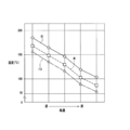
- FIG. 8 shows a state of temperature change according to the wind speed blown from the blower opening 27 in each part of the LED 5, the substrate 6, and the heat sink 10, and the waveform l5 shown by the solid line in FIG.
- a waveform 16 shown is a back surface of the substrate 6, and a waveform 110 shown by a one-dot chain line shows a temperature change according to the wind speed at the base 11 of the heat sink 10.
- the LED 5 can be reliably cooled together with the substrate 6 and the heat sink 10 as the wind speed of the air blown from the blower opening 27 is increased.
- the base portion 11 extends radially outward with respect to the LED 5, heat from the LED 5 is transferred to the radially outer side of the base portion 11 and further transferred to the heat radiating portion 12 via the base portion 11. 1 (see arrow Dh1 in FIG. 1), and heat can be diffused and dissipated over a wide range without heat immediately after the LED 5.
- the base 11 extends radially outward with respect to the LED 5, the heat dissipation effect of the LED 5 can be obtained while suppressing the plate thickness (t11) (thickness in the front-rear direction) of the base 11 from becoming thick as much as possible. Therefore, the weight of the heat sink 10 can be prevented and the productivity can be increased.
- the blower 20 is arranged in the heat sink internal space 10A while ensuring a heat radiation effect, so that the vehicle lamp 1 As a whole, both compactness and heat dissipation effect can be achieved.
- the LED 5 is provided in front of the base 11 and is provided in the center of the base 11 in a front view (see FIG. 4).
- the heat radiating portion 12 is extended until the front end 12t is positioned forward of the LED 5.
- the heat dissipating part 12 extends forward from the LED 5, the space in the limited lamp chamber 3, that is, the front and rear length between the outer lens 2 and the LED 5 can be effectively utilized for compactization.
- the surface area of the heat radiating part 12 can be enlarged to improve heat dissipation.
- the distance between the LED 5 as the heat source and the outer lens 2 disposed in front of the LED 5 is normally inevitably provided in consideration of an optical viewpoint, but the heat dissipating part 12 extends forward from the LED 5.
- interval can be utilized effectively.
- the heat radiation part 12 is provided with a longer back than the front of the base part 11. That is, the rear extension 14 is longer than the front extension 13 (see FIG. 1).
- the heat radiating portion 12 extends as long as possible in the front-rear direction, but the layout relationship with the outer lens 2 disposed in front of the base portion 11.
- the length of the heat radiating portion 12 extending forward is limited.
- the heat radiating portion 12 can be extended to the back without being subjected to such a restriction, and the heat radiating property can be further improved (see arrow Dh2r in FIG. 1).
- the heat radiating portion 12 is provided in the circumferential direction, and the heat radiating portion main body 15 extends in the front-rear direction from the heat radiating portion main body 15 in the radial direction and is disposed in the circumferential direction.
- a plurality of radiating fins 16 are formed, and the radiating fins 17 are formed to direct the blown air toward the outer lens 2.
- the surface area of the heat radiating portion 12 can be enlarged and the heat radiation performance thereof can be enhanced.
- the air blown from the air blowing openings 27 can be directed to the outer lens 2 along the air guide paths 17 while being guided by the heat radiating fins 16.
- the radiating fins 16 are provided with a protruding length (h16) longer than the thickness (t11) of the base 11 (see FIG. 5).
- the heat radiation fin 16 since the protrusion length of the heat radiation fin 16 is longer than the thickness of the base 11 formed thick in order to increase the heat absorption property to the LED 5, the heat radiation fin having a sufficiently long protrusion length. 16 can be provided, and the surface area of the heat dissipating part 12 can be enlarged to improve heat dissipation.
- the air guiding path 17 has a wind guiding (guide) function by the radiating fins 16 of the air blown from the air blowing openings 27. Can be increased.
- the blower device 20 is configured to jet from a blower opening 27 provided in a portion corresponding to the air guide path 17 in the circumferential direction of the heat radiating unit 12 (FIGS. 2, 4, and 5). reference).
- the piezo fan unit 21 as the blower source of the blower 20 as in the present embodiment, for example.
- the piezo fan unit 21 has a low static pressure (flow rate) although the flow rate of the blown air is low and the flow rate of the blown air is less likely to be a vortex than the type rotating around the axis such as a cooling fan equipped with a propeller. Due to the characteristics, the air jetted from the blower opening 27 can be blown far along the air guide path 17. That is, the directivity toward the outer lens 2 in the front can be improved by jetting forward from the air blowing opening 27 provided at the rear end of the air guide path 17 extending in the front-rear direction.
- the front indicates the irradiation direction of the light source
- the back (rear) indicates the opposite direction to the irradiation direction of the light source.
- the irradiation direction of the LED 5 and the vehicle Although the example in which the front of the LED matches and the example in which the irradiation direction of the LED 5 matches the irradiation direction of the lamp unit have been described, it does not necessarily have to match.
- the front indicates the direction toward the reflector until the light emitted from the LED 5 is refracted by the reflector and the reflector. After refraction, the direction toward the outer lens (outside the vehicular lamp) is indicated.
Landscapes
- Engineering & Computer Science (AREA)
- General Engineering & Computer Science (AREA)
- Physics & Mathematics (AREA)
- Microelectronics & Electronic Packaging (AREA)
- Optics & Photonics (AREA)
- Non-Portable Lighting Devices Or Systems Thereof (AREA)
- Arrangement Of Elements, Cooling, Sealing, Or The Like Of Lighting Devices (AREA)
Priority Applications (3)
| Application Number | Priority Date | Filing Date | Title |
|---|---|---|---|
| US16/485,758 US10851964B2 (en) | 2017-02-24 | 2018-02-06 | Lighting fixture for vehicle |
| EP18758254.9A EP3581845B1 (de) | 2017-02-24 | 2018-02-06 | Fahrzeugbeleuchtungsvorrichtung |
| CN201880012905.7A CN110312892B (zh) | 2017-02-24 | 2018-02-06 | 车辆用灯具 |
Applications Claiming Priority (2)
| Application Number | Priority Date | Filing Date | Title |
|---|---|---|---|
| JP2017032916A JP6451758B2 (ja) | 2017-02-24 | 2017-02-24 | 車両用灯具 |
| JP2017-032916 | 2017-02-24 |
Publications (1)
| Publication Number | Publication Date |
|---|---|
| WO2018155176A1 true WO2018155176A1 (ja) | 2018-08-30 |
Family
ID=63254425
Family Applications (1)
| Application Number | Title | Priority Date | Filing Date |
|---|---|---|---|
| PCT/JP2018/004092 Ceased WO2018155176A1 (ja) | 2017-02-24 | 2018-02-06 | 車両用灯具 |
Country Status (5)
| Country | Link |
|---|---|
| US (1) | US10851964B2 (de) |
| EP (1) | EP3581845B1 (de) |
| JP (1) | JP6451758B2 (de) |
| CN (1) | CN110312892B (de) |
| WO (1) | WO2018155176A1 (de) |
Families Citing this family (4)
| Publication number | Priority date | Publication date | Assignee | Title |
|---|---|---|---|---|
| CN109210496A (zh) * | 2018-10-16 | 2019-01-15 | 北京汽车研究总院有限公司 | 一种具有特殊防雾结构的灯具和具有其的车辆 |
| JP2023064595A (ja) * | 2021-10-26 | 2023-05-11 | ベジ 佐々木 | 電子装置及びヘッドライト |
| FR3137743B1 (fr) * | 2022-07-11 | 2024-08-02 | Valeo Vision | Dissipateur thermique de module lumineux pour véhicule automobile et module lumineux pour véhicule automobile |
| KR20240169331A (ko) * | 2023-05-24 | 2024-12-03 | 현대모비스 주식회사 | 차량용 램프 시스템 |
Citations (6)
| Publication number | Priority date | Publication date | Assignee | Title |
|---|---|---|---|---|
| JP2010027583A (ja) * | 2008-07-24 | 2010-02-04 | Koito Mfg Co Ltd | 車両用灯具 |
| JP2010254099A (ja) | 2009-04-23 | 2010-11-11 | Koito Mfg Co Ltd | 車両用灯具 |
| JP2011108382A (ja) * | 2009-11-13 | 2011-06-02 | Koito Mfg Co Ltd | 車両用灯具 |
| JP2014044900A (ja) * | 2012-08-28 | 2014-03-13 | Endo Lighting Corp | ヒートシンクおよびこれを用いたled照明器具 |
| JP2016192556A (ja) * | 2012-04-11 | 2016-11-10 | 東芝ライテック株式会社 | 光半導体光源及び車両用照明装置 |
| JP2017000036A (ja) * | 2015-06-08 | 2017-01-05 | 清水建設株式会社 | 緑化ベンチ |
Family Cites Families (8)
| Publication number | Priority date | Publication date | Assignee | Title |
|---|---|---|---|---|
| DE102007043961C5 (de) * | 2007-09-14 | 2017-04-06 | Automotive Lighting Reutlingen Gmbh | Beleuchtungseinrichtung mit Halbleiterlichtquelle |
| JP4945433B2 (ja) * | 2007-12-28 | 2012-06-06 | シャープ株式会社 | 照明装置 |
| JP2009295513A (ja) * | 2008-06-06 | 2009-12-17 | Koito Mfg Co Ltd | 車両用灯具 |
| CN102803842B (zh) * | 2009-06-25 | 2015-07-01 | 皇家飞利浦电子股份有限公司 | 热管理设备 |
| US10168018B2 (en) * | 2014-02-25 | 2019-01-01 | Ford Global Technologies, Llc | Vehicle light fixture having internal heatsink for LED lamp |
| KR20150106688A (ko) * | 2014-03-12 | 2015-09-22 | 에스엘 주식회사 | 차량용 램프 모듈 |
| KR20160122014A (ko) * | 2015-04-13 | 2016-10-21 | 엘지이노텍 주식회사 | 헤드 램프의 결로 발생 방지 장치 |
| JP6464941B2 (ja) * | 2015-06-25 | 2019-02-06 | 株式会社デンソー | 車両用灯具 |
-
2017
- 2017-02-24 JP JP2017032916A patent/JP6451758B2/ja not_active Expired - Fee Related
-
2018
- 2018-02-06 EP EP18758254.9A patent/EP3581845B1/de active Active
- 2018-02-06 CN CN201880012905.7A patent/CN110312892B/zh not_active Expired - Fee Related
- 2018-02-06 WO PCT/JP2018/004092 patent/WO2018155176A1/ja not_active Ceased
- 2018-02-06 US US16/485,758 patent/US10851964B2/en not_active Expired - Fee Related
Patent Citations (6)
| Publication number | Priority date | Publication date | Assignee | Title |
|---|---|---|---|---|
| JP2010027583A (ja) * | 2008-07-24 | 2010-02-04 | Koito Mfg Co Ltd | 車両用灯具 |
| JP2010254099A (ja) | 2009-04-23 | 2010-11-11 | Koito Mfg Co Ltd | 車両用灯具 |
| JP2011108382A (ja) * | 2009-11-13 | 2011-06-02 | Koito Mfg Co Ltd | 車両用灯具 |
| JP2016192556A (ja) * | 2012-04-11 | 2016-11-10 | 東芝ライテック株式会社 | 光半導体光源及び車両用照明装置 |
| JP2014044900A (ja) * | 2012-08-28 | 2014-03-13 | Endo Lighting Corp | ヒートシンクおよびこれを用いたled照明器具 |
| JP2017000036A (ja) * | 2015-06-08 | 2017-01-05 | 清水建設株式会社 | 緑化ベンチ |
Also Published As
| Publication number | Publication date |
|---|---|
| US10851964B2 (en) | 2020-12-01 |
| EP3581845B1 (de) | 2021-04-07 |
| EP3581845A4 (de) | 2020-01-22 |
| EP3581845A1 (de) | 2019-12-18 |
| US20200018458A1 (en) | 2020-01-16 |
| CN110312892A (zh) | 2019-10-08 |
| JP6451758B2 (ja) | 2019-01-16 |
| JP2018137201A (ja) | 2018-08-30 |
| CN110312892B (zh) | 2021-11-05 |
Similar Documents
| Publication | Publication Date | Title |
|---|---|---|
| JP5342553B2 (ja) | 車両用灯具 | |
| US8147109B2 (en) | Heat dissipation device of vehicle lamp and interposing element thereof | |
| US7329033B2 (en) | Convectively cooled headlamp assembly | |
| JP5160992B2 (ja) | 車両用灯具 | |
| CN102003668A (zh) | 一种汽车头灯 | |
| JP6451758B2 (ja) | 車両用灯具 | |
| JP5243505B2 (ja) | 車両用前照灯 | |
| CN209909794U (zh) | 冷却单元以及车辆用灯具 | |
| JP5606627B2 (ja) | 車載用ヘッドランプ | |
| JP6439813B2 (ja) | 車両用灯具 | |
| JP2010108637A (ja) | 車両用前照灯 | |
| JP5491828B2 (ja) | 車両用灯具 | |
| JP4661740B2 (ja) | 車両用led灯具 | |
| JP2009295513A (ja) | 車両用灯具 | |
| JP2013016681A (ja) | 放熱部材および放熱機構 | |
| JP4702230B2 (ja) | 車両用led灯具 | |
| TWI335402B (en) | Led lamp with a heat sink | |
| JP6493429B2 (ja) | 車両用灯具 | |
| JP6654959B2 (ja) | 車両用灯具 | |
| JP2009245833A (ja) | 車両用灯具 | |
| US20240263759A1 (en) | Heat-dissipation car lamp | |
| KR20150019787A (ko) | 방열 성능이 향상된 히트 싱크 및 이를 구비하는 차량용 헤드 램프 | |
| JP5909699B2 (ja) | 車両用前照灯 | |
| JP2016100141A (ja) | 発光装置 |
Legal Events
| Date | Code | Title | Description |
|---|---|---|---|
| 121 | Ep: the epo has been informed by wipo that ep was designated in this application |
Ref document number: 18758254 Country of ref document: EP Kind code of ref document: A1 |
|
| NENP | Non-entry into the national phase |
Ref country code: DE |
|
| ENP | Entry into the national phase |
Ref document number: 2018758254 Country of ref document: EP Effective date: 20190909 |