WO2018155293A1 - Amortisseur - Google Patents
Amortisseur Download PDFInfo
- Publication number
- WO2018155293A1 WO2018155293A1 PCT/JP2018/005179 JP2018005179W WO2018155293A1 WO 2018155293 A1 WO2018155293 A1 WO 2018155293A1 JP 2018005179 W JP2018005179 W JP 2018005179W WO 2018155293 A1 WO2018155293 A1 WO 2018155293A1
- Authority
- WO
- WIPO (PCT)
- Prior art keywords
- pressure
- extension
- valve
- chamber
- passage
- Prior art date
- Legal status (The legal status is an assumption and is not a legal conclusion. Google has not performed a legal analysis and makes no representation as to the accuracy of the status listed.)
- Ceased
Links
Images


Classifications
-
- F—MECHANICAL ENGINEERING; LIGHTING; HEATING; WEAPONS; BLASTING
- F16—ENGINEERING ELEMENTS AND UNITS; GENERAL MEASURES FOR PRODUCING AND MAINTAINING EFFECTIVE FUNCTIONING OF MACHINES OR INSTALLATIONS; THERMAL INSULATION IN GENERAL
- F16F—SPRINGS; SHOCK-ABSORBERS; MEANS FOR DAMPING VIBRATION
- F16F9/00—Springs, vibration-dampers, shock-absorbers, or similarly-constructed movement-dampers using a fluid or the equivalent as damping medium
- F16F9/32—Details
- F16F9/44—Means on or in the damper for manual or non-automatic adjustment; such means combined with temperature correction
- F16F9/46—Means on or in the damper for manual or non-automatic adjustment; such means combined with temperature correction allowing control from a distance, i.e. location of means for control input being remote from site of valves, e.g. on damper external wall
-
- F—MECHANICAL ENGINEERING; LIGHTING; HEATING; WEAPONS; BLASTING
- F16—ENGINEERING ELEMENTS AND UNITS; GENERAL MEASURES FOR PRODUCING AND MAINTAINING EFFECTIVE FUNCTIONING OF MACHINES OR INSTALLATIONS; THERMAL INSULATION IN GENERAL
- F16F—SPRINGS; SHOCK-ABSORBERS; MEANS FOR DAMPING VIBRATION
- F16F9/00—Springs, vibration-dampers, shock-absorbers, or similarly-constructed movement-dampers using a fluid or the equivalent as damping medium
- F16F9/32—Details
- F16F9/48—Arrangements for providing different damping effects at different parts of the stroke
- F16F9/49—Stops limiting fluid passage, e.g. hydraulic stops or elastomeric elements inside the cylinder which contribute to changes in fluid damping
Definitions
- This invention relates to a shock absorber.
- shock absorbers used in vehicle suspensions have a damping valve that can vary the damping force.
- a shock absorber includes a cylinder, a piston that divides the cylinder into an extension side chamber and a pressure side chamber, a piston rod that is connected to the piston at one end and is movably inserted into the cylinder, and a damping valve. Composed.
- the damping valve opens and closes an extension side passage and a pressure side passage, which communicate with the extension side chamber and the pressure side chamber provided in the piston, and opens and closes the extension side passage and the pressure side passage, respectively.
- the expansion side leaf valve, the compression side leaf valve, the expansion side spool and the compression side spool that press the expansion side leaf valve and the compression side leaf valve, respectively, the expansion side back pressure chamber and the compression side back that press the expansion side spool and the compression side spool with internal pressure
- an electromagnetic pressure control valve for adjusting the pressure in the pressure chamber.
- the damping force at the time of expansion and contraction can be controlled by controlling the pressure in the expansion-side back pressure chamber and the pressure-side back pressure chamber by a single electromagnetic pressure control valve.
- the extension side back pressure chamber and the pressure side back pressure chamber are connected by a communication path.
- the communication passage communicates with the electromagnetic pressure control valve.
- This communication path is formed by an annular gap formed on the outer periphery of the separator by providing a vertical hole in the holding shaft of the piston holder that holds the piston, and inserting a pipe-shaped separator into the vertical hole.
- the strength of the piston holder is inevitably lowered due to the fact that a vertical hole is provided in the holding shaft and the separator is inserted.
- an object of the present invention is to provide a shock absorber capable of reducing the number of parts and ensuring the strength of the piston holder.
- the expansion-side back pressure chamber that urges the expansion-side spool toward the expansion-side leaf valve and the compression-side back pressure chamber that urges the compression-side spool toward the compression-side leaf valve communicate with each other. Since the communication path is formed on the outer periphery of the holding shaft, there is no need to provide a separator for providing the communication path in the holding shaft.
- FIG. 1 is a cross-sectional view of a shock absorber according to an embodiment.
- FIG. 2 is an enlarged cross-sectional view of the electromagnetic pressure control valve of the shock absorber in one embodiment.
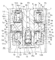
- FIG. 3 is an enlarged cross-sectional view of the piston portion of the shock absorber according to the embodiment.
- the shock absorber D in one embodiment opens and closes a cylinder 1, an annular piston 2 that is slidably inserted into the cylinder 1, and an extension-side passage 3 provided in the piston 2.
- An extension side leaf valve Ve a pressure side leaf valve Vp that opens and closes a pressure side passage 4 provided in the piston 2, an extension side chamber member 12 and an extension side spool Se, a pressure side chamber member 11 and a pressure side spool Sp, and a piston holder 8
- the groove 8h functioning as a communication path, the expansion pilot orifice Pe as the expansion resistance element, the compression pilot orifice Pp as the compression resistance element, the adjustment path Pc connected to the groove 8h, and the adjustment path Pc
- a pressure side discharge passage Ep that allows only the flow of liquid toward the side chamber R1, and an extension side discharge that allows only the flow of liquid from the adjustment passage Pc to the pressure side chamber R2.
- road Ee is constituted by an electromagnetic pressure control valve 6 provided in the regulation passage Pc to control the upstream pressure regulating passage Pc.
- the cylinder 1 is filled with a liquid such as hydraulic oil, the lower end is closed, although not shown, and an annular rod guide is attached to the upper end.
- a free piston that slides in the cylinder 1 is provided below the cylinder 1 in FIG. 1, and a gas chamber is formed in the cylinder 1 by the free piston.
- the liquid with which the cylinder 1 is filled can be used if it is a liquid which can exhibit damping force besides hydraulic oil.
- the piston 2 is slidably inserted into the cylinder 1, and defines an extension side chamber R1 and a pressure side chamber R2 filled with liquid in the cylinder 1, and is movably inserted into the cylinder 1. It is connected to one end of the piston rod 7.
- the piston rod 7 is inserted through the inner periphery of the rod guide (not shown) provided at the upper end of the cylinder 1 and protrudes outside the cylinder 1.
- a seal (not shown) is provided between the piston rod 7 and the cylinder 1, and the cylinder 1 is in a liquid-tight state.
- the shock absorber D Since the shock absorber D is set to a so-called single rod type, the volume of the piston rod 7 that enters and exits the cylinder 1 as the shock absorber D expands and contracts is the volume of the gas in the gas chamber described above. By expanding or contracting, the free piston moves up and down in the cylinder 1 to be compensated. As described above, the shock absorber D is set to a single cylinder type, but instead of installing a free piston and a gas chamber, a reservoir is provided on the outer periphery or outside of the cylinder 1 and the volume compensation of the piston rod 7 is performed by the reservoir. May be performed.
- the piston rod 7 has a piston holder 8 that holds the piston 2 and an electromagnetic valve housing that forms a hollow housing portion L that is connected to the piston holder 8 and that houses the electromagnetic pressure control valve 6 together with the piston holder 8.
- a cylinder 9 and a rod member 10 having one end connected to the solenoid valve housing cylinder 9 and the other end protruding outward from the upper end of the cylinder 1 are formed.
- the piston holder 8 includes a holding shaft 8a on which the annular piston 2 is mounted on the outer periphery, a flange 8b provided on the outer periphery of the upper end of the holding shaft 8a in FIG. 1, and a cylindrical shape provided on the outer periphery of the upper end of the flange 8b in FIG. And a socket 8c.
- the piston holder 8 is opened from the tip of the holding shaft 8a, extends in the axial direction, communicates with the socket 8c, a port 8e that passes through the flange 8b and communicates with the socket 8c, and a diagram of the holding shaft 8a.
- the solenoid valve housing cylinder 9 includes a top-cylindrical housing cylinder portion 9a and a cylindrical connecting portion that has an outer diameter smaller than that of the housing cylinder portion 9a and extends upward from the top of the housing cylinder portion 9a in FIG. 9b and a through-hole 9c that opens from the side of the accommodating tube portion 9a and communicates with the inside. Then, when the socket 8c of the piston holder 8 is screwed to the inner periphery of the accommodating cylinder portion 9a of the electromagnetic valve accommodating cylinder 9 and the piston holder 8 is integrated with the electromagnetic valve accommodating cylinder 9, the electromagnetic valve accommodating cylinder 9 and the piston holder are integrated.
- the accommodating part L in which the electromagnetic pressure control valve 6 is accommodated is formed in the accommodating cylinder part 9a.
- the accommodating portion L functions as a part of the adjustment passage Pc, communicates with the groove 8h provided on the outer periphery of the holding shaft 8a via the port 8e, and forms the extension-side discharge passage Ee.
- the pressure side chamber R2 communicates with the vertical hole 8d.
- the through hole 9c faces the recess 8i, and cooperates with the through hole 8j to allow the housing portion L to communicate with the extension side chamber R1. It is like that.
- an annular valve body 22a is attached to the recess 8i provided on the outer periphery of the upper end in FIG. 1 of the socket 8c.
- the annular valve body 22a is urged by a spring 22b from above in FIG. Open and close.
- the annular valve body 22 a and the spring 22 b constitute a check valve 22.
- the pressure-side discharge passage Ep is formed by a through-hole 9c, a recess 8i, and a through-hole 8j, and only the flow of liquid from the adjustment passage Pc to the extension-side chamber R1 is allowed by the check valve 22 described above. Block the flow of liquid in the opposite direction.
- the above-described vertical hole 8d provided in the holding shaft 8a functions as the extension side discharge passage Ee, and the vertical hole 8d provided in the holding shaft 8a goes from the accommodating portion L to the compression side chamber R2 through the vertical hole 8d.
- a check valve 25 that allows only the flow of liquid is provided.
- the check valve 25 is seated on the pipe 25a mounted in the vertical hole 8d, a cup-shaped spring receiver 25b fitted to the pipe 25a, and an end of the pipe 25a and accommodated in the spring receiver 25b.
- a disc-like valve body 25c, and a spring 25d interposed between the top of the spring receiver 25b and the valve body 25c.
- the spring receiver 25b is provided with a notch, and when the valve body 25c is separated from the pipe 25a, the check valve 25 is opened to allow the flow of liquid from the vertical hole 8d side toward the pressure side chamber R2.
- the valve body 25c contacts the lower end of the pipe 25a in FIG. 1 and the check valve 25 closes to block the liquid flow.
- the check valve 25 is assembled and accommodated in the vertical hole 8d, and is fixed to the vertical hole 8d by a disc spring fitted near the outlet of the vertical hole 8d. Therefore, the extension side discharge passage Ee blocks the flow of liquid from the pressure side chamber R2 toward the adjustment passage Pc, and allows only the flow of liquid from the adjustment passage Pc toward the pressure side chamber R2.
- the rod member 10 has a cylindrical shape, and the inner circumference at the lower end in FIG. 1 has an enlarged diameter, allows insertion of the connecting portion 9b of the solenoid valve housing cylinder 9, and enables the connecting portion 9b to be screwed. A screw portion (not shown) is provided. Thus, when the rod member 10, the solenoid valve housing cylinder 9, and the piston holder 8 are integrated, the piston rod 7 is formed by these.
- a harness H for supplying power to a solenoid which will be described later, is inserted into the rod member 10 and the connecting portion 9b of the solenoid valve housing cylinder 9, and the upper end of the harness H is not shown, but the upper end of the rod member 10 is not shown. Is connected to the power supply.
- the outer periphery of the holding shaft 8 a provided in the piston holder 8 slides on the outer periphery of the shim 61 and the shim 61 formed by laminating a plurality of annular plates together with the annular piston 2.
- a pressure-side annular plate 62 that is freely mounted, a pressure-side stopper 63 that is annular and has an outer diameter larger than that of the shim 61, and the pressure-side chamber member 11 are assembled in an overlapping manner.
- annular pressure side leaf valve Vp that is slidably mounted on the outer periphery of the shim 61 is provided on the piston 2, and the pressure side leaf valve Vp is connected to the holding shaft of the piston holder 8 via the shim 61. It is attached to the outer periphery of 8a.
- the pressure side chamber member 11 is slidably mounted with a pressure side spool Sp that is in contact with the pressure side annular plate 62, and the pressure side spool Sp is movable in the axial direction so as to move together with the pressure side chamber member 11. Is forming.
- a shim 65 as a shaft member configured by laminating a plurality of annular plates, and an extended-side annular plate 66 that is slidably mounted on the outer periphery of the shim 65,
- An extension side stopper 67 and an extension side chamber member 12 which are annular and have an outer diameter larger than that of the shim 65 are assembled in an overlapping manner.
- an annular extension side leaf valve Ve that is slidably mounted on the outer periphery of the shim 65 is provided on the piston 2, and the extension side leaf valve Ve is connected to the piston holder 8 via the shim 65. It is attached to the outer periphery of the holding shaft 8a.
- An extension side spool Se that contacts the extension side annular plate 66 is slidably attached to the extension side chamber member 12, and the extension side spool Se can be moved in the axial direction.
- an extension side back pressure chamber Ce is formed.
- the outer diameter of the extension side leaf valve Ve is smaller than the outer diameter of the compression side leaf valve Vp.
- each component mounted on the outer periphery of the holding shaft 8a described above is fixed by the extension-side chamber member 12 screwed into a screw portion 8f formed at the tip of the holding shaft 8a.
- the piston 2 is annular and is mounted on the outer periphery of the holding shaft 8a of the piston holder 8, and an extension side passage 3 and a pressure side passage 4 that connect the extension side chamber R1 and the pressure side chamber R2 are formed.
- 3 at the upper end of the piston 2, there is an annular window 2a communicating with the pressure side passage 4, an annular pressure side valve seat 2b provided on the outer peripheral side of the annular window 2a and surrounding the pressure side passage 4, and an annular window 2a.
- seat part 2c provided in the inner periphery is provided.
- annular window 2d communicated with the extension side passage 3
- annular extension side valve seat 2e provided on the outer peripheral side of the annular window 2d and surrounding the extension side passage 3, and an annular window 2d.
- seat part 2f provided in the inner periphery is provided.
- the extension-side leaf valve Ve is annular in order to allow insertion of the holding shaft 8 a of the piston holder 8.
- the extension-side leaf valve Ve is composed of a single annular plate. It may be configured by laminating a single annular plate.
- the extension side leaf valve Ve configured as described above is overlapped below the piston 2 in FIG. 3 and can be attached to and detached from the extension side valve seat 2e and the inner peripheral seat portion 2f.
- the extension side leaf valve Ve is provided with a notch Oe that functions as an orifice when seated on the extension side valve seat 2e on the outer periphery thereof, and is slidably mounted on the outer periphery of the shim 65.
- an expansion side annular plate 66 that is superimposed on the expansion side leaf valve Ve is slidably mounted.
- an annular auxiliary valve 71 having an outer diameter smaller than that of the expansion side annular plate 66 is stacked on the side of the expansion side annular plate 66 opposite to the leaf valve side.
- the outer periphery of the shim 65 is slidably mounted.
- the axial length when the extension-side leaf valve Ve, the extension-side annular plate 66 and the auxiliary valve 71 are stacked is made shorter than the axial length of the shim 65.
- an extension side stopper 67 is provided below the shim 65 in FIG. 3 and has an annular shape whose outer diameter is set larger than the inner diameters of the auxiliary valve 71 and the extension side annular plate 66.
- the extension side chamber member 12 is stacked below the side stopper 67. Accordingly, the extension side leaf valve Ve, the extension side annular plate 66 and the auxiliary valve 71 are guided by the shim 65 so as to be movable in the vertical direction in FIG. 3 which is the axial direction between the piston 2 and the extension side stopper 67. It has become.
- the extension-side leaf valve Ve When the extension-side leaf valve Ve is pressed by pressure from the extension-side passage 3 side, the outer periphery bends together with the extension-side annular plate 66, and the extension-side leaf plate Ve and the auxiliary valve 71 as a whole are separated from the piston 2. Can retreat.
- the retraction amounts of the extension side leaf valve Ve, the extension side annular plate 66 and the auxiliary valve 71 from the piston 2 are set by the axial length of the shim 65.
- the shim 65 is constituted by a plurality of annular plates, the shim 65 can be adjusted by the number of laminated annular plates, but the shim 65 may be constituted by a single annular plate.
- the expansion side annular plate 66 is bent and has higher rigidity than the expansion side leaf valve Ve. For this reason, the axial length (thickness) of the expansion side annular plate 66 is longer than the axial length (thickness) of the expansion side leaf valve Ve.
- the expansion-side annular plate 66 may be formed of a material having higher rigidity than the side leaf valve Ve.
- the inner diameter of the expansion side annular plate 66 is set to be smaller than the outer diameter of the inner peripheral sheet portion 2f provided in the piston 2.
- the outer diameter of the expansion side annular plate 66 is set to be larger than the inner diameter of the expansion side valve seat 2e.
- the extension-side back pressure chamber Ce urges the extension-side spool Se toward the extension-side annular plate 66 with the pressure introduced inside. Therefore, the extension side leaf valve Ve stacked on the extension side annular plate 66 is urged toward the piston 2 by the urging force received from the extension side spool Se and the pressure of the extension side back pressure chamber Ce.
- the extension side annular plate 66 When the expansion side annular plate 66 is pressed from the back side by the pressure in the expansion side back pressure chamber Ce and the expansion side spool Se, and the expansion side leaf valve Ve is seated on the expansion side valve seat 2e and the inner peripheral seat portion 2f, The extension side annular plate 66 is supported by the inner peripheral seat portion 2f and the extension side valve seat 2e. Therefore, the pressure in the extension side back pressure chamber Ce and the urging force of the extension side spool Se are received by the extension side annular plate 66, and deformation of the extension side leaf valve Ve is suppressed, and the extension side leaf valve Ve is overloaded. It is not to take.
- the auxiliary valve 71 has an outer diameter smaller than that of the extension side leaf valve Ve and the extension side annular plate 66.
- auxiliary valve 71 when the extension side leaf valve Ve and the extension side annular plate 66 are bent by the pressure of the extension side passage 3, the outer peripheral side is more easily bent than the auxiliary valve 71.
- the damping characteristic of damping force can be tuned. If the auxiliary valve 71 is unnecessary due to the damping characteristic generated in the shock absorber D, it can be omitted. Conversely, a plurality of auxiliary valves 71 may be stacked.
- the extension-side chamber member 12 is disposed on the opposite side of the extension-side leaf valve Ve from the piston, and has a cylindrical spacer 121 that is screwed to the outer periphery of the holding shaft 8a of the piston holder 8, and an outer periphery of the spacer 121. And a sliding contact cylinder 122 that is fitted and in sliding contact with the expansion side spool Se.
- the spacer 121 includes a cylindrical portion 121a that is screwed to the screw portion 8f of the holding shaft 8a, a flange 121b that is provided on the outer periphery of the lower end in FIG.
- the sliding contact cylinder 122 includes a cylindrical portion 122a in which the extension side spool Se is in sliding contact with the inner periphery, and a flange 122b that protrudes to the inner periphery at the lower end in FIG. 3 of the cylindrical portion 122a.
- the cylindrical portion 121a of the spacer 121 is fitted to the inner periphery of the flange 122b of the sliding contact tube 122.
- the spacer 121 and the sliding contact tube 122 are integrated to form an annular recess.
- the extension-side back pressure chamber Ce is formed by the annular recess.
- the extension side chamber member 12 is constituted by the spacer 121 and the sliding contact cylinder 122 in order to facilitate processing, but may be constituted by one part.
- the annular groove 121c on the inner periphery of the spacer 121 faces the groove 8h provided on the holding shaft 8a, and the extension side back pressure chamber Ce passes through the pressure side pilot orifice Pp. It communicates with the groove 8h.
- An extension side stopper 67 is interposed between the spacer 121 and the shim 65 in the extension side chamber member 12, but the extension side stopper 67 is abolished so that the spacer 121 functions as a stopper.
- the lower limit of movement of the plate 66 may be restricted.
- the extension side spool Se is accommodated in the sliding tube 122.
- the extension-side spool Se is in sliding contact with the inner periphery of the cylindrical portion 122 a of the sliding contact cylinder 122, and can move in the axial direction within the sliding contact cylinder 122.
- the extension-side spool Se includes an annular spool body 13 and an annular protrusion 14 that rises from the inner periphery of the upper end of the spool body 13 in FIG.
- the inner diameter of the annular protrusion 14 is set to be smaller than the outer diameter of the extended-side annular plate 66 so that the annular protrusion 14 can come into contact with the lower surface in FIG. Yes.
- the inner diameter of the spool body 13 is larger than the outer diameter of the cylindrical portion 121a of the spacer 121, but the inner diameter is set to a diameter that is in sliding contact with the outer periphery of the cylindrical portion 121a to extend the extension-side back pressure chamber Ce. You may seal with the side spool Se.
- the sliding contact cylinder 122 of the extension side chamber member 12 is provided with a pressure side pressure introduction passage Ip that passes through the flange 122b and communicates the extension side back pressure chamber Ce and the pressure side chamber R2.
- An annular valve body 15 is superimposed on the upper end of the flange 122b of the sliding contact cylinder 122 in FIG. 3, and is annularly formed by a spring 16 interposed between the annular valve body 15 and the spool body 13 of the extension side spool Se. The valve body 15 is pressed against the flange 122b.
- the pressure side pressure introduction passage Ip is considered so as not to cause resistance to the flow of the passing liquid.
- the annular valve body 15 When the pressure side chamber R2 is compressed and the pressure is increased during the contraction operation of the shock absorber D, the annular valve body 15 is pressed by this pressure and is separated from the flange 122b to open the pressure side pressure introduction passage Ip. Further, when the shock absorber D is extended so that the pressure in the extension side back pressure chamber Ce becomes higher than the pressure side chamber R2, it is pressed against the flange 122b to close the pressure side pressure introduction passage Ip, and only the liquid flow from the pressure side chamber R2 is allowed to flow. Allow. As described above, the annular valve body 15 and the spring 16 constitute the pressure-side check valve Tp, and only allow the flow of liquid from the pressure-side chamber R2 toward the extension-side back pressure chamber Ce through the pressure-side pressure introduction passage Ip. It is set as a passage for traffic.
- the spring 16 plays a role of pressing the annular valve body 15 against the flange 122b, constitutes a compression-side check valve Tp together with the annular valve body 15, and serves to urge the extension-side spool Se toward the extension-side leaf valve Ve. Is also responsible. Therefore, when the extension side leaf valve Ve is bent and the extension side spool Se is pushed down in the direction away from the piston 2 and then the extension side leaf valve Ve is flexed, the extension side spool Se is quickly moved by the spring force of the spring 16. Return to the original position (position shown in FIG. 3).
- extension side spool Se can be energized by a separate spring, there is an advantage that the compression side check valve Tp and the spring 16 can be shared, the number of parts can be reduced, and the structure can be simplified.
- the outer diameter of the extension side spool Se is set to be larger than the inner diameter of the annular protrusion 14, and the annular protrusion 14 comes into contact with the extension side annular plate 66.
- the pressure in the extension side back pressure chamber Ce is always urged toward the extension side leaf valve Ve.
- the pressure side leaf valve Vp overlaid on the piston 2 has an annular shape to allow the holding shaft 8a of the piston holder 8 to be inserted, as in the extension side leaf valve Ve.
- it is constituted by one annular plate, it may be constituted by laminating a plurality of annular plates.
- the pressure side leaf valve Vp comprised in this way is piled up the upper direction in FIG. 3 of the piston 2, and can be attached / detached to the pressure side valve seat 2b and the inner peripheral seat part 2c.
- the pressure-side leaf valve Vp is provided with a notch Op that functions as an orifice when seated on the pressure-side valve seat 2b on the outer periphery thereof, and is slidably mounted on the outer periphery of the shim 61.
- a pressure side annular plate 62 that is superimposed on the pressure side leaf valve Vp is slidably mounted.
- an annular auxiliary valve 81 having an outer diameter smaller than that of the pressure side annular plate 62 is stacked on the pressure side leaf valve side of the pressure side annular plate 62, and this auxiliary valve 81 is also connected to the shim 61. It is slidably mounted on the outer periphery.
- the axial length when the pressure side leaf valve Vp, the pressure side annular plate 62 and the auxiliary valve 81 are stacked is set to be shorter than the axial length of the shim 61.
- a pressure side stopper 63 is provided above the shim 61 in FIG. 3 and has an annular shape whose outer diameter is set larger than the inner diameter of the auxiliary valve 81 and the pressure side annular plate 62.
- the compression side chamber member 11 is overlaid on the upper side. Therefore, the pressure-side leaf valve Vp, the pressure-side annular plate 62, and the auxiliary valve 81 are guided by the shim 61 and can move up and down in FIG. 3, which is the axial direction between the piston 2 and the pressure-side stopper 63. .
- the pressure-side leaf valve Vp When the pressure-side leaf valve Vp is pressed by pressure from the pressure-side passage 4 side, the outer periphery thereof bends together with the pressure-side annular plate 62, and the pressure-side leaf plate Vp and the auxiliary valve 81 can be moved away from the piston 2 as a whole.
- the retraction amounts of the pressure side leaf valve Vp, the pressure side annular plate 62 and the auxiliary valve 81 from the piston 2 are set by the length of the shim 61 in the axial direction.
- the shim 61 since the shim 61 is constituted by a plurality of annular plates, the shim 61 can be adjusted by the number of laminated annular plates, but the shim 61 may be constituted by a single annular plate.
- the pressure side annular plate 62 is bent and has higher rigidity than the pressure side leaf valve Vp. For this reason, the axial length (thickness) of the compression-side annular plate 62 is longer than the axial length (thickness) of the compression-side leaf valve Vp, but not only the rigidity is increased by the axial length but also the compression-side leaf valve.
- the compression side annular plate 62 may be formed of a material having higher rigidity than Vp.
- the inner diameter of the compression side annular plate 62 is set to be smaller than the outer diameter of the inner peripheral sheet portion 2c provided in the piston 2.
- the outer diameter of the pressure side annular plate 62 is set to be larger than the inner diameter of the pressure side valve seat 2b.
- the pressure-side back pressure chamber Cp urges the pressure-side spool Sp toward the pressure-side annular plate 62 with the pressure introduced inside. Therefore, the pressure side leaf valve Vp overlapping the pressure side annular plate 62 is urged toward the piston 2 by the urging force received from the pressure side spool Sp and the pressure in the pressure side back pressure chamber Cp.
- the pressure side annular plate 62 When the pressure side annular plate 62 is pressed from the back side by the pressure in the pressure side back pressure chamber Cp and the pressure side spool Sp, and the pressure side leaf valve Vp is seated on the pressure side valve seat 2b and the inner peripheral seat portion 2c, the pressure side annular plate 62 is The inner circumferential seat portion 2c and the pressure side valve seat 2b are supported. Therefore, the pressure in the pressure side back pressure chamber Cp and the urging force by the pressure side spool Sp are received by the pressure side annular plate 62, the deformation of the pressure side leaf valve Vp is suppressed, and the pressure side leaf valve Vp is not overloaded. ing.
- the auxiliary valve 81 has an outer diameter smaller than that of the pressure side leaf valve Vp and the pressure side annular plate 62. Therefore, when the pressure side leaf valve Vp and the pressure side annular plate 62 are bent by the pressure of the pressure side passage 4, the outer peripheral side is more easily bent than the auxiliary valve 81, and the auxiliary side valve 81 is used to attenuate the pressure side damping force. You can tune the characteristics. If the auxiliary valve 81 is unnecessary due to the damping characteristic generated in the shock absorber D, it can be omitted. Conversely, a plurality of auxiliary valves 81 may be stacked.
- the pressure side chamber member 11 is disposed on the side opposite to the piston of the pressure side leaf valve Vp, and is fitted to the outer periphery of the spacer 111 and the cylindrical spacer 111 fitted to the outer periphery of the holding shaft 8 a in the piston holder 8. And a sliding cylinder 112 with which the compression side spool Sp slides.
- the spacer 111 is mounted on the outer periphery of the holding shaft 8a, and opens from the recess 111a provided on the entire outer periphery of the upper end in FIG. 3, the annular groove 111b provided on the inner periphery, and the annular groove 111b.
- the slidable contact cylinder 112 includes a cylinder portion 112a in which the compression side spool Sp is slidably contacted on the inner periphery, and a flange 112b protruding from the upper end inner periphery in FIG. 3 of the cylinder portion 112a.
- the spacer 111 and the sliding contact cylinder 112 are integrated to form an annular recess, and the pressure side back pressure chamber Cp is formed in the annular recess. It is formed.
- the pressure side chamber member 11 is composed of the spacer 111 and the sliding contact cylinder 112 in order to facilitate processing, but it may be composed of one part.
- the annular groove 111b on the inner periphery of the spacer 111 faces the groove 8h provided on the holding shaft 8a, and the pressure-side back pressure chamber Cp is grooved through the expansion-side pilot orifice Pe. 8h.
- the pressure side chamber member 11 is in close contact with the upper end in FIG. 3 in contact with the flange 8 b of the piston holder 8.
- the groove 8h is formed by the piston 2, shims 61 and 65, the extension side stopper 67 and the compression side stopper 63, the extension side chamber member 12 and the compression side chamber member 11 mounted on the holding shaft 8a, and the extension side chamber R1 and the pressure side chamber R2. Communication has been cut off.
- the groove 8h communicates with the accommodating portion L through the port 8e, is connected to the adjustment passage Pc, and extends through the compression side pilot orifice Pp and through the expansion side pilot orifice Pe and the compression side back pressure chamber through the extension side pilot orifice Pe. Connected to Cp. As described above, the groove 8h forms a communication path that communicates with the expansion-side back pressure chamber Ce via the compression-side resistance element and also communicates with the compression-side back pressure chamber Cp via the expansion-side resistance element.
- the pressure side stopper 63 is interposed between the spacer 111 and the shim 61 in the pressure side chamber member 11, but the pressure side stopper 63 is abolished so that the spacer 111 functions as a stopper. You may make it regulate a movement minimum.
- a compression side spool Sp is accommodated in the sliding contact cylinder 112 in the sliding contact cylinder 112, a compression side spool Sp is accommodated.
- the pressure side spool Sp is in sliding contact with the inner periphery of the cylindrical portion 112 a of the sliding contact cylinder 112, and can move in the axial direction within the sliding contact cylinder 112.
- the pressure-side spool Sp includes an annular spool body 17 and an annular protrusion 18 that rises from the outer periphery of the lower end of the spool body 17 in FIG.
- the inner diameter of the annular protrusion 18 is set to be smaller than the outer diameter of the pressure-side annular plate 62 so that the annular protrusion 18 can come into contact with the upper surface in FIG.
- the inner diameter of the spool body 17 is larger than the outer diameter of the spacer 111, the inner diameter may be set to a diameter that is in sliding contact with the outer periphery of the spacer 111, and the compression-side back pressure chamber Cp may be sealed with the compression-side spool Sp. Good.
- the sliding contact cylinder 112 of the compression side chamber member 11 is provided with an expansion side pressure introduction passage Ie that passes through the flange 112b and communicates the compression side back pressure chamber Cp and the expansion side chamber R1.
- An annular valve body 19 is superimposed on the lower end of the flange 112b of the sliding contact cylinder 112 in FIG. 3, and an annular valve body is provided by a spring 20 interposed between the annular valve body 19 and the spool body 17 of the compression side spool Sp. 19 is pressed against the flange 112b.
- the extension side pressure introduction passage Ie is considered so as not to cause resistance to the flow of the passing liquid.
- the annular valve body 19 and the spring 20 constitute the extension-side check valve Te, and only allow the flow of liquid from the extension-side chamber R1 toward the compression-side back pressure chamber Cp through the extension-side pressure introduction passage Ie. It is set as a one-way passage.
- the spring 20 plays a role of pressing the annular valve body 19 against the flange 112b, constitutes an extension check valve Te together with the annular valve body 19, and plays a role of urging the pressure side spool Sp toward the pressure side leaf valve Vp. Also bears. Therefore, when the pressure-side leaf valve Vp is bent and the pressure-side spool Sp is pushed up in the direction away from the piston 2 and the bending of the pressure-side leaf valve Vp is eliminated, the pressure-side spool Sp is quickly returned to the original position (by the spring force of the spring 20). Return to the position shown in FIG.
- the pressure side spool Sp can be biased by a separate spring, there is an advantage that the extension side check valve Te and the spring 20 can be shared, the number of parts can be reduced, and the structure can be simplified.
- the outer diameter of the pressure side spool Sp is set to be larger than the inner diameter of the annular protrusion 18 so that the annular protrusion 18 comes into contact with the pressure side annular plate 62.
- the pressure in the chamber Cp is always urged toward the compression side leaf valve Vp.
- the pressure receiving area which receives the pressure of the extension side back pressure chamber Ce of the extension side spool Se is a difference between the area of a circle whose diameter is the outer diameter of the extension side spool Se and the area of the circle whose diameter is the inner diameter of the annular protrusion 14. It becomes.
- the pressure receiving area that receives the pressure of the pressure side back pressure chamber Cp of the pressure side spool Sp is a difference between the area of the circle having the outer diameter of the pressure side spool Sp as the diameter and the area of the circle having the inner diameter of the annular protrusion 18 as the diameter.
- the pressure receiving area where the pressure of the expansion side back pressure chamber Ce directly acts on the expansion side annular plate 66 is from the area of a circle whose diameter is the inner diameter of the annular protrusion 14 to the circle whose diameter is the outer diameter of the shim 65. It is the area excluding the area. Therefore, the force obtained by multiplying the area obtained by subtracting the area of the circle having the outer diameter of the shim 65 from the area of the circle having the outer diameter of the extension side spool Se as the diameter of the extension side back pressure chamber Ce is the extension side load. Acting on the extension side leaf valve Ve. The extension side leaf valve Ve is biased toward the piston 2 by the extension side load.
- extension-side annular plate 66 may be eliminated and the annular protrusion 14 may be brought into direct contact with the back surface of the extension-side leaf valve Ve. Also in this case, since the extension side leaf valve Ve is mounted on the outer periphery of the shim 65, the same extension side load as that when the extension side annular plate 66 is provided acts on the extension side leaf valve Ve.
- the pressure receiving area where the pressure of the pressure side back pressure chamber Cp directly acts on the pressure side annular plate 62 is the area of the circle whose diameter is the outer diameter of the shim 61 from the area of the circle whose diameter is the inner diameter of the annular protrusion 18. Excluded area. Therefore, the force obtained by multiplying the area obtained by subtracting the area of the circle having the outer diameter of the shim 61 from the area of the circle having the outer diameter of the compression side spool Sp by the pressure of the compression side back pressure chamber Cp as the compression side load is the compression side leaf. Acts on the valve Vp. The pressure side leaf valve Vp is urged toward the piston 2 by the pressure side load.
- the pressure side annular plate 62 may be eliminated and the annular protrusion 18 may be brought into direct contact with the back surface of the pressure side leaf valve Vp. Also in this case, since the pressure side leaf valve Vp is mounted on the outer periphery of the shim 61, the same pressure side load as when the pressure side annular plate 62 is provided acts on the pressure side leaf valve Vp.
- the extension side load is increased by the extension side spool Se. It is determined only by the pressure receiving area that receives the pressure of the side back pressure chamber Ce.
- the pressure side load is the pressure side back pressure chamber of the pressure side spool Sp. It depends only on the pressure receiving area that receives the pressure of Cp.
- the expansion side load acting on the expansion side leaf valve Ve can be set by the pressure receiving area that receives the pressure in the expansion side back pressure chamber Ce of the expansion side spool Se.
- the pressure side load acting on the pressure side leaf valve Vp can be set by the pressure receiving area that receives the pressure in the pressure side back pressure chamber Cp of the pressure side spool Sp.
- the pressure receiving areas of the compression side spool Sp and the expansion side spool Se are made equal, but the difference between the expansion side load and the compression side load can be given by setting the pressure receiving area.
- an adjustment passage Pc is provided to connect the downstream side of the communication passage formed by the groove 8h that connects the extension side back pressure chamber Ce and the pressure side back pressure chamber Cp, and the upstream side of the extension side discharge passage Ee and the pressure side discharge passage Ep. It has been.
- An electromagnetic pressure control valve 6 is provided in the middle of the adjustment passage Pc so that the pressures in the upstream extension-side back pressure chamber Ce and the pressure-side back pressure chamber Cp can be controlled.
- the electromagnetic pressure control valve 6 closes the adjustment passage Pc when not energized and performs pressure control when energized.
- a fail valve FV that bypasses the electromagnetic pressure control valve 6 is provided in the middle of the adjustment passage Pc.
- the electromagnetic pressure control valve 6 includes a valve seat member 30 including a valve housing cylinder 30a and a control valve valve seat 30d, and an electromagnetic valve valve body that is attached to and detached from the control valve valve seat 30d. 31 and a solenoid Sol that applies thrust to the solenoid valve body 31 and drives it in the axial direction.
- valve seat member 30 is fitted into the socket 8c of the piston holder 8, and the diameter of the valve seat member 30 is inserted by inserting the valve housing cylinder 30a into the inner periphery of the annular valve housing 32 that is superimposed on the upper end of the flange 8b in FIG. It is accommodated in the accommodating part L, being positioned in the direction.
- the valve housing 32 has an annular shape, an annular window 32a provided at the upper end in FIG. 2, a port 32b that opens from the annular window 32a and communicates with the lower end in FIG. 2, and an upper end in FIG.
- a notch groove 32c that opens from the inner periphery and communicates with the port 32b, a vertical groove 32d that is provided on the outer periphery and extends along the axial direction, and an annular fail valve seat 32e that surrounds the outer periphery of the annular window 32a. Configured.
- the port 32b faces the opening facing the upper end of the flange 8b of the port 8e, and the port 32b and the cutout groove 32c have the port 8e. Further, the vertical groove 32d is communicated with the notch 8g provided in the flange 8b.
- the port 32b and the notch groove 32c are communicated with the groove 8h forming the communication path through the port 8e, and further, the expansion side back pressure chamber Ce and the pressure side back pressure are connected via the expansion side pilot orifice Pe and the pressure side pilot orifice Pp. It communicates with the chamber Cp. Further, the vertical groove 32d communicates with the pressure side chamber R2 through the expansion side discharge passage Ee formed by the notch 8g, the vertical hole 8d, and the check valve 25, and the through hole 9c, the recess 8i, the through hole 8j, and the check.
- the pressure side discharge passage Ep formed by the valve 22 communicates with the extension side chamber R1.
- valve accommodating cylinder 30a in the cylindrical valve seat member 30 is accommodated.
- the valve seat member 30 has a bottomed cylindrical shape and has a valve accommodating cylinder 30a having a flange 30b on the outer periphery of the upper end in FIG. 2, a through hole 30c that opens from the side of the valve accommodating cylinder 30a and communicates with the inside,
- An annular control valve seat 30d that protrudes in the axial direction is provided at the upper end in FIG. 2 of the valve housing cylinder 30a.
- a fail valve body 33 which is an annular leaf valve is mounted on the outer periphery of the valve housing cylinder 30a of the valve seat member 30, a fail valve body 33 which is an annular leaf valve is mounted.
- the fail valve body 33 has an inner periphery that is the flange 30b of the valve seat member 30 and the upper end of the valve housing 32 in FIG. It is clamped by the inner periphery and fixed. Therefore, the fail valve body 33 is seated in the state where the initial deflection is given to the annular fail valve seat 32e provided on the valve housing 32 on the outer peripheral side, and closes the annular window 32a.
- the fail valve body 33 bends when the pressure acting in the annular window 32a through the port 32b reaches the valve opening pressure, opens the annular window 32a, and connects the port 32b to the extension side discharge passage Ee and the pressure side discharge passage Ep. Communicate.
- a fail valve FV is formed by the fail valve body 33 and the fail valve seat 32e.
- valve housing cylinder 30a When the valve housing cylinder 30a is inserted into the valve housing 32 and the valve seat member 30 is assembled to the valve housing 32, the notch groove 32c provided in the valve housing 32 faces the through hole 30c provided in the valve housing cylinder 30a.
- the extension-side back pressure chamber Ce and the compression-side back pressure chamber Cp are communicated with each other in the valve housing cylinder 30a through the port 32b.
- valve fixing member 35 that is annular and contacts the upper end of the flange 30b in FIG. 1 is stacked above the valve seat member 30 in FIG.
- a solenoid Sol accommodated in the valve accommodating cylinder 9 is disposed.
- the valve fixing member 35 has a notch groove 35 a so that the inner circumferential space of the valve fixing member 35 can communicate with the outer circumferential space of the valve seat member 30 even when abutting against the flange 30 b of the valve seat member 30. Is provided. This communication may be performed not by the notch groove 35a but by a hole such as a port.
- the solenoid Sol is a top-cylindrical molded stator 36 in which a winding 37 and a harness H that energizes the winding 37 are integrated with a mold resin, and a top-cylindrical cylindrical stator that is fitted to the inner periphery of the mold stator 36.
- the first fixed iron core 38, the annular second fixed iron core 39 superimposed on the lower end in FIG. 1 of the molded stator 36, and the first fixed iron core 38 and the second fixed iron core 39 are magnetically interposed. Fixed to the inner periphery of the movable core 41, the filler ring 40 that forms a gap, the cylindrical movable core 41 that is axially movable on the inner peripheral side of the first fixed core 38 and the second fixed core 39.
- the solenoid Sol attracts the movable iron core 41 by energizing the winding 37 and applies a downward thrust to the shaft 42 in FIG.
- the shaft 42 is in contact with the electromagnetic valve body 31, and the solenoid Sol applies a downward thrust in FIG. 2 to the electromagnetic valve body 31 when energized.
- a solenoid valve body 31 is slidably inserted into the valve seat member 30.
- the solenoid valve body 31 is provided on the side of the valve seat member 30 that is slidably inserted into the valve housing cylinder 30a of the valve seat member 30 and the counter valve seat member side that is the upper side of the small diameter portion 31a in FIG.
- the solenoid valve body 31 is formed with the large-diameter portion 31b with the outer diameter on the side opposite to the valve seat member larger than the small-diameter portion 31a with the recess 31c as a boundary.
- the electromagnetic valve body 31 includes a seating portion 31g facing the control valve valve seat 30d at the lower end in FIG. 2 of the large-diameter portion 31b, and the seating portion 31g is controlled when moved in the axial direction with respect to the valve seat member 30.
- the valve seat 30d is detached and seated. That is, the electromagnetic pressure control valve 6 includes the electromagnetic valve body 31 and the valve seat member 30. When the seating portion 31g is seated on the control valve valve seat 30d, the electromagnetic pressure control valve 6 is closed.
- a coil spring 34 is interposed between the flange 30b of the valve seat member 30 and the spring receiving portion 31d to urge the electromagnetic valve valve body 31 in a direction away from the valve seat member 30. Therefore, the electromagnetic valve body 31 is always urged in the direction away from the valve seat member 30 by the coil spring 34, and if a thrust force against the coil spring 34 from the solenoid Sol does not act, It is positioned at the most distant position.
- the coil spring 34 is used to urge the solenoid valve valve body 31 in the direction away from the valve seat member 30, but the urging force can be exerted in addition to the coil spring 34.
- An elastic body that can be used can be used.
- the solenoid valve body 31 When the solenoid valve body 31 is farthest from the valve seat member 30, the small diameter portion 31a is opposed to the through hole 30c to close the through hole 30c.
- the solenoid Sol When the solenoid Sol is energized to move the solenoid valve valve 31 by a predetermined amount from the position farthest away from the valve seat member 30 to the valve seat member 30 side, the solenoid valve valve 31 always places the recess 31c into the through hole 30c.
- the through holes 30c are opened so as to face each other.
- the solenoid valve body 31 opens the through hole 30c and the seating portion 31g is separated from the control valve valve seat 30d, the through hole 30c passes through the recess 31c of the solenoid valve valve body 31 and the notch groove 35a provided in the valve fixing member 35.
- the expansion side discharge passage Ee and the pressure side discharge passage Ep are communicated.
- the pressure on the upstream side of the electromagnetic pressure control valve 6 can be controlled according to the thrust of the solenoid Sol. Since the upstream side of the electromagnetic pressure control valve 6 communicates with the expansion side back pressure chamber Ce and the pressure side back pressure chamber Cp via the adjustment passage Pc, the electromagnetic pressure control valve 6 causes the expansion side back pressure chamber Ce and the pressure side to communicate with each other. The pressure in the back pressure chamber Cp can be controlled. Therefore, the expansion side load and the compression side load can be controlled by adjusting the pressures of the expansion side back pressure chamber Ce and the compression side back pressure chamber Cp according to the energization amount to the solenoid Sol.
- the downstream side of the electromagnetic pressure control valve 6 communicates with the expansion side discharge passage Ee and the pressure side discharge passage Ep, and the liquid that has passed through the electromagnetic pressure control valve 6 causes the pressure side chamber R2 on the low pressure side during the expansion operation of the shock absorber D.
- the shock absorber D When the shock absorber D is contracted, it is discharged into the low-pressure side expansion chamber R1. Therefore, the adjustment passage Pc is formed by the port 8e, the port 32b, the notch groove 32c, a part of the accommodating portion L, and the vertical groove 32d.
- the electromagnetic pressure control valve 6 has a blocking position in which the through hole 30c in the valve seat member 30 is closed by the small diameter portion 31a in the electromagnetic valve body 31 during a failure in which the solenoid Sol cannot be energized. Therefore, the electromagnetic pressure control valve 6 functions not only as a pressure control valve but also as an on-off valve.
- the fail valve FV opens and closes an annular window 32a that communicates with the port 32b, and the valve opening pressure is set to a pressure that exceeds the upper limit pressure that can be controlled by the electromagnetic pressure control valve 6.
- the electromagnetic pressure control valve 6, the port 32b is communicated with the expansion side discharge passage Ee and the pressure side discharge passage Ep.
- the fail valve FV is opened, and the pressures in the extension-side back pressure chamber Ce and the pressure-side back pressure chamber Cp are opened.
- the valve pressure can be controlled. Therefore, for example, when the electromagnetic pressure control valve 6 is in the shut-off position at the time of failure, the pressures in the extension side back pressure chamber Ce and the pressure side back pressure chamber Cp are controlled to the valve opening pressure of the fail valve FV.
- a space K is formed in the valve housing cylinder 30a and on the tip side from the through hole 30c.
- the space K communicates with the outside of the solenoid valve valve body through a communication path 31e provided in the solenoid valve valve body 31 and an orifice 31f.
- the liquid in the extension side chamber R1 pushes open the extension side check valve Te, passes through the extension side pressure introduction passage Ie, and flows into the adjustment passage Pc.
- the liquid that has passed through the adjustment passage Pc pushes the check valve 25 open and is discharged to the low pressure side pressure side chamber R2 through the extension side discharge passage Ee.
- the expansion side pilot orifice Pe gives a resistance when the liquid passes and causes a pressure loss. Since the liquid is flowing, the expansion side pilot orifice Pe has a lower pressure than the expansion side chamber R1 downstream of the adjustment passage Pc.
- the check valve 22 provided on Ep remains closed without opening.
- the expansion-side pressure introduction passage Ie not only communicates with the compression-side back pressure chamber Cp but also communicates with the expansion-side back pressure chamber Ce through the groove 8h, but the compression-side pressure introduction passage Ip is closed by the compression-side check valve Tp. Therefore, when the shock absorber D is extended, the pressure in the extension side back pressure chamber Ce is higher than that of the compression side chamber R2.
- the pressure in the pressure side back pressure chamber Cp is higher than that in the pressure side chamber R2 on the low pressure side, but there is no inconvenience because it only energizes the pressure side leaf valve Vp that closes the pressure side passage 4 where no liquid flows. .
- the electromagnetic pressure control valve 6 is provided in the adjustment passage Pc, and if the solenoid Sol of the electromagnetic pressure control valve 6 is energized to control the pressure on the upstream side of the adjustment passage Pc, the extension side back pressure is increased.
- the extension side load can be controlled to a desired load by adjusting the pressure in the chamber Ce.
- the extension side load controlled by the electromagnetic pressure control valve 6 acts in the valve closing direction, and the pressure in the extension side chamber R1 acts in the valve opening direction through the extension side passage 3.
- the extension-side leaf valve Ve opens when the extension-side load exceeds the force due to the action of the pressure in the extension-side chamber R1, and slides on the outer periphery of the shim 65 to a position where the two balance each other and retracts from the piston 2.
- the retraction amount by which the extension-side leaf valve Ve is separated from the piston 2 is determined according to the extension-side load. Therefore, the retraction amount can be controlled according to the energization amount to the solenoid Sol.
- the opening degree of the extension side leaf valve Ve can be controlled by the electromagnetic pressure control valve 6, and thereby the extension side damping force when the buffer D is extended can be adjusted in magnitude.
- the liquid in the pressure side chamber R2 pushes and opens the pressure side check valve Tp, passes through the pressure side pressure introduction passage Ip, and flows to the adjustment passage Pc.
- the liquid that has passed through the adjustment passage Pc pushes the check valve 22 open and is discharged to the low-pressure-side extension side chamber R1 through the pressure-side discharge passage Ep.
- the pressure side pilot orifice Pp provides resistance when the liquid passes and causes a pressure loss. In the state where the liquid flows, the pressure side pilot orifice Pp has a pressure lower than the pressure side chamber R2 downstream of the adjustment passage Pc.
- the check valve 25 provided at Ee is not opened and remains closed.
- the compression-side pressure introduction passage Ip not only communicates with the expansion-side back pressure chamber Ce but also communicates with the compression-side back pressure chamber Cp through the groove 8h, but the expansion-side pressure introduction passage Ie is blocked by the expansion-side check valve Te. Therefore, the pressure in the compression side back pressure chamber Cp becomes higher than that of the expansion side chamber R1 when the shock absorber D is contracted.
- the pressure in the extension side back pressure chamber Ce is higher than that in the extension side chamber R1 on the low pressure side, but it only energizes the extension side leaf valve Ve that closes the extension side passage 3 where no liquid flows. There is no inconvenience.
- the pressure side load valve controlled by the electromagnetic pressure control valve 6 acts on the pressure side leaf valve Vp in the valve closing direction, and the pressure in the pressure side chamber R2 acts on the pressure side passage 4 in the valve opening direction.
- the pressure-side leaf valve Vp opens when the force due to the action of the pressure in the pressure-side chamber R2 exceeds the pressure-side load, slides on the outer periphery of the shim 61 to a position where both balance, and moves backward from the piston 2.
- the retraction amount by which the pressure-side leaf valve Vp is separated from the piston 2 is determined according to the pressure-side load. Therefore, the retraction amount can be controlled according to the energization amount to the solenoid Sol.
- the opening degree of the pressure side leaf valve Vp can be controlled by the electromagnetic pressure control valve 6, whereby the pressure side damping force when the shock absorber D is contracted can be adjusted in magnitude.
- the outer diameter of the extension side leaf valve Ve is smaller than the outer diameter of the compression side leaf valve Vp, and receives the pressure of the extension side chamber R1 of the extension side leaf valve Ve.
- the pressure receiving area is smaller than the pressure receiving area that receives the pressure of the pressure side chamber R2 of the pressure side leaf valve Vp. Therefore, even if the extension side load and the compression side load are the same in the electromagnetic pressure control valve 6, the valve opening pressure of the extension side leaf valve Ve becomes larger than the valve opening pressure of the compression side leaf valve Vp, and the extension side damping force is reduced to the compression side. Can be greater than force.
- the communication path that communicates the extension-side back pressure chamber Ce and the pressure-side back pressure chamber Cp is provided on the outer periphery of the holding shaft 8a of the piston holder 8, and therefore communicates with the holding shaft 8a.
- a separator is not required for forming the communication path, the number of parts can be reduced, the cost can be reduced, and the separator 8 is not provided in the holding shaft 8a, so the diameter of the vertical hole 8d can be reduced. Since the diameter can be reduced, the strength of the piston holder 8 can be secured.
- the groove 8h is not connected to the expansion side pressure introduction passage Ie and the pressure side pressure introduction passage Ip by the above-described components including the piston 2 assembled to the holding shaft 8a. Closed to prevent communication.
- Each of the components assembled to the holding shaft 8a is fixed to the holding shaft 8a in close contact with the load in the axial direction by the spacer 121 functioning as a piston nut, so that the groove 8h can be closed tightly. Therefore, in the shock absorber D of the present invention, since the liquid does not leak from the groove 8h functioning as the communication path to the extension side chamber R1 or the pressure side chamber R2, the problem that the damping force characteristic varies for each product is solved.
- the cross-sectional shape of the groove 8h forming the communication path can be designed arbitrarily.
- the communication path is formed by a groove 8h provided on the outer periphery of the holding shaft 8a.
- a gap that forms the communication path is formed between the holding shaft 8a and the parts assembled to the holding shaft 8a. Therefore, for example, a chamfer along the axial direction is formed on the outer periphery of the holding shaft 8a, and a gap is provided between each part assembled to the holding shaft 8a at this chamfered portion to provide a communication path. It may be formed. Even if it does in this way, the effect similar to the case where a communicating path is formed in the groove
- channel 8h is acquired.
- the expansion side pilot orifice (extension side resistance element) Pe is provided in the compression side chamber member 11
- the compression side pilot orifice (pressure side resistance element) Pp is provided in the expansion side chamber member 12.
- the expansion resistance element and the compression resistance element are provided on the piston holder side, for example, when there are four types of expansion resistance elements and compression resistance elements, respectively, in order to realize all these combinations, the total 16 different piston holders had to be prepared.
- the extension side resistance element and the compression side resistance element are separately provided in the corresponding extension side chamber member 12 and compression side chamber member 11, four types of extension side chamber member 12 and compression side chamber member 11 are prepared. All you need to do is Therefore, when the shock absorber D is configured in this manner, tuning of the extension side resistance element and the compression side resistance element is facilitated, the number of parts to be managed is reduced, and the cost can be further reduced.
- the holding shaft 8a of the piston holder 8 is provided with a vertical hole 8d communicating with the compression side chamber R2, and an expansion side discharge passage Ee is formed, and the adjustment passage Pc is formed in the vertical hole 8d.
- a pipe 25a that functions as a valve seat for the check valve 25 that allows only the flow of liquid from the pressure side chamber R2 is provided.
- the extension side leaf valve Ve and the pressure side leaf valve Vp are slidably fitted to the outer circumferences of the shims 65 and 61, respectively, so that they can be separated from the piston 2.
- a structure in which the inner peripheral side is fixed to the holding shaft 8a may be employed.
- the electromagnetic pressure control valve 6 is not limited to the above-described specific structure because it only needs to be able to adjust the pressure in the extension side back pressure chamber Ce and the pressure side back pressure chamber Cp.
Landscapes
- Engineering & Computer Science (AREA)
- General Engineering & Computer Science (AREA)
- Mechanical Engineering (AREA)
- Fluid-Damping Devices (AREA)
Abstract
Dans l'amortisseur (D) de la présente invention, un canal de communication (8h), qui permet la communication entre une chambre de contre-pression côté extension (Ce) qui pousse une bobine côté extension (Se) vers une soupape à lamelle côté extension (Ve) et une chambre de contre-pression côté pression (Cp) qui pousse une bobine côté pression (Sp) vers une soupape à lamelle côté pression (Vp), est formé dans la périphérie externe d'un arbre de maintien (8a).
Applications Claiming Priority (2)
| Application Number | Priority Date | Filing Date | Title |
|---|---|---|---|
| JP2017032824A JP2018136013A (ja) | 2017-02-24 | 2017-02-24 | 緩衝器 |
| JP2017-032824 | 2017-02-24 |
Publications (1)
| Publication Number | Publication Date |
|---|---|
| WO2018155293A1 true WO2018155293A1 (fr) | 2018-08-30 |
Family
ID=63253808
Family Applications (1)
| Application Number | Title | Priority Date | Filing Date |
|---|---|---|---|
| PCT/JP2018/005179 Ceased WO2018155293A1 (fr) | 2017-02-24 | 2018-02-15 | Amortisseur |
Country Status (2)
| Country | Link |
|---|---|
| JP (1) | JP2018136013A (fr) |
| WO (1) | WO2018155293A1 (fr) |
Cited By (1)
| Publication number | Priority date | Publication date | Assignee | Title |
|---|---|---|---|---|
| WO2022070642A1 (fr) * | 2020-09-29 | 2022-04-07 | Kyb株式会社 | Soupape d'amortissement et absorbeur de chocs |
Families Citing this family (1)
| Publication number | Priority date | Publication date | Assignee | Title |
|---|---|---|---|---|
| JP7165032B2 (ja) * | 2018-11-26 | 2022-11-02 | Kyb株式会社 | 減衰バルブ |
Citations (4)
| Publication number | Priority date | Publication date | Assignee | Title |
|---|---|---|---|---|
| JP2005351419A (ja) * | 2004-06-11 | 2005-12-22 | Kayaba Ind Co Ltd | 油圧緩衝器 |
| JP2008215433A (ja) * | 2007-03-01 | 2008-09-18 | Kayaba Ind Co Ltd | 緩衝器のバルブ構造 |
| JP2014031853A (ja) * | 2012-08-06 | 2014-02-20 | Kayaba Ind Co Ltd | 緩衝装置 |
| JP2015072047A (ja) * | 2013-10-03 | 2015-04-16 | カヤバ工業株式会社 | 液圧緩衝器 |
-
2017
- 2017-02-24 JP JP2017032824A patent/JP2018136013A/ja active Pending
-
2018
- 2018-02-15 WO PCT/JP2018/005179 patent/WO2018155293A1/fr not_active Ceased
Patent Citations (4)
| Publication number | Priority date | Publication date | Assignee | Title |
|---|---|---|---|---|
| JP2005351419A (ja) * | 2004-06-11 | 2005-12-22 | Kayaba Ind Co Ltd | 油圧緩衝器 |
| JP2008215433A (ja) * | 2007-03-01 | 2008-09-18 | Kayaba Ind Co Ltd | 緩衝器のバルブ構造 |
| JP2014031853A (ja) * | 2012-08-06 | 2014-02-20 | Kayaba Ind Co Ltd | 緩衝装置 |
| JP2015072047A (ja) * | 2013-10-03 | 2015-04-16 | カヤバ工業株式会社 | 液圧緩衝器 |
Cited By (5)
| Publication number | Priority date | Publication date | Assignee | Title |
|---|---|---|---|---|
| WO2022070642A1 (fr) * | 2020-09-29 | 2022-04-07 | Kyb株式会社 | Soupape d'amortissement et absorbeur de chocs |
| JP2022055572A (ja) * | 2020-09-29 | 2022-04-08 | Kyb株式会社 | 減衰バルブおよび緩衝器 |
| CN116194697A (zh) * | 2020-09-29 | 2023-05-30 | Kyb株式会社 | 阻尼阀以及缓冲器 |
| JP7485579B2 (ja) | 2020-09-29 | 2024-05-16 | カヤバ株式会社 | 減衰バルブおよび緩衝器 |
| CN116194697B (zh) * | 2020-09-29 | 2026-02-17 | Kyb株式会社 | 阻尼阀以及缓冲器 |
Also Published As
| Publication number | Publication date |
|---|---|
| JP2018136013A (ja) | 2018-08-30 |
Similar Documents
| Publication | Publication Date | Title |
|---|---|---|
| KR101914398B1 (ko) | 감쇠 밸브 및 완충기 | |
| JP6239921B2 (ja) | 液圧緩衝器 | |
| US11614140B2 (en) | Damping valve and shock absorber | |
| CN105531498B (zh) | 阻尼阀 | |
| CN105008757B (zh) | 阻尼阀 | |
| US20230287955A1 (en) | Damping force generation mechanism and pressure shock absorber | |
| KR20180030094A (ko) | 감쇠 밸브 및 감쇠 밸브를 구비한 완충기 | |
| JP5713462B2 (ja) | 減衰バルブ | |
| CN116194697A (zh) | 阻尼阀以及缓冲器 | |
| WO2018155293A1 (fr) | Amortisseur | |
| JP6442247B2 (ja) | バルブ | |
| JP6442248B2 (ja) | 減衰バルブ及び緩衝器 | |
| JP6262977B2 (ja) | 液圧緩衝器 | |
| JP6059549B2 (ja) | ソレノイドバルブ | |
| JP6514492B2 (ja) | 減衰バルブ及び緩衝器 | |
| US20190128360A1 (en) | Damping force-adjusting valve and shock absorber | |
| JP2019138401A (ja) | 緩衝器 | |
| JP7579383B1 (ja) | 減衰バルブおよび緩衝器 | |
| JP2018141477A (ja) | 緩衝器 |
Legal Events
| Date | Code | Title | Description |
|---|---|---|---|
| 121 | Ep: the epo has been informed by wipo that ep was designated in this application |
Ref document number: 18757356 Country of ref document: EP Kind code of ref document: A1 |
|
| NENP | Non-entry into the national phase |
Ref country code: DE |
|
| 122 | Ep: pct application non-entry in european phase |
Ref document number: 18757356 Country of ref document: EP Kind code of ref document: A1 |