WO2018155476A1 - 筆記具 - Google Patents
筆記具 Download PDFInfo
- Publication number
- WO2018155476A1 WO2018155476A1 PCT/JP2018/006158 JP2018006158W WO2018155476A1 WO 2018155476 A1 WO2018155476 A1 WO 2018155476A1 JP 2018006158 W JP2018006158 W JP 2018006158W WO 2018155476 A1 WO2018155476 A1 WO 2018155476A1
- Authority
- WO
- WIPO (PCT)
- Prior art keywords
- tip
- writing
- barrel
- writing core
- peripheral surface
- Prior art date
- Legal status (The legal status is an assumption and is not a legal conclusion. Google has not performed a legal analysis and makes no representation as to the accuracy of the status listed.)
- Ceased
Links
Images



Classifications
-
- B—PERFORMING OPERATIONS; TRANSPORTING
- B43—WRITING OR DRAWING IMPLEMENTS; BUREAU ACCESSORIES
- B43K—IMPLEMENTS FOR WRITING OR DRAWING
- B43K24/00—Mechanisms for selecting, projecting, retracting or locking writing units
- B43K24/02—Mechanisms for selecting, projecting, retracting or locking writing units for locking a single writing unit in only fully projected or retracted positions
-
- B—PERFORMING OPERATIONS; TRANSPORTING
- B43—WRITING OR DRAWING IMPLEMENTS; BUREAU ACCESSORIES
- B43K—IMPLEMENTS FOR WRITING OR DRAWING
- B43K21/00—Propelling pencils
- B43K21/02—Writing-core feeding mechanisms
- B43K21/16—Writing-core feeding mechanisms with stepwise feed of writing-cores
-
- B—PERFORMING OPERATIONS; TRANSPORTING
- B43—WRITING OR DRAWING IMPLEMENTS; BUREAU ACCESSORIES
- B43K—IMPLEMENTS FOR WRITING OR DRAWING
- B43K21/00—Propelling pencils
- B43K21/02—Writing-core feeding mechanisms
- B43K21/22—Writing-cores gripping means, e.g. chucks
Definitions
- Embodiments of the present invention relate to a writing instrument including a position adjusting mechanism capable of adjusting an arrangement position of a movable member movable in the axial direction.
- a writing instrument having a position adjusting mechanism that allows a user to adjust the arrangement position of a movable member that can move in the axial direction of the writing instrument is known.
- the movable member is screwed to the position adjustment mechanism main body, and the user adjusts the screwed portion by urging it in the axial direction by an elastic body such as a coil spring. The arranged position was held.
- a slide sleeve that is movable in the front-rear direction by being screwed into the outer cylindrical portion and rotated integrally with the rear dial sleeve, and the slide sleeve is rotated.
- a mechanical pencil is known that includes an inner cylindrical portion that is freely screwed and a tip shaft that is rotatably screwed to the outer cylindrical portion and is movable in the front-rear direction (see Patent Document 1).
- Japanese Patent Application Publication No. 2004-223820 see, for example, Claim 1-3, Paragraph 0009, Paragraph 0019-0026, and FIG. 3).
- a writing instrument including a position adjustment mechanism that can reduce the difference in holding force due to the difference in the arrangement position of the adjusted movable member as compared with the related art.
- the purpose is to provide.
- a writing instrument includes a position adjustment mechanism that adjusts an arrangement position of a movable member that is movable in an axial direction, and the position adjustment mechanism moves the movable member from a radial direction. It has a pressing member to press.
- a writing instrument including a position adjustment mechanism that can reduce the difference in holding force due to the difference in the arrangement position of the adjusted movable member as compared with the related art.
- FIG. 4 is a partially enlarged cross-sectional view showing a part of the writing core gripping and feeding mechanism shown in FIG. It is sectional drawing which cut
- FIG. 4 is a partially enlarged cross-sectional view showing a part of the writing core gripping and feeding mechanism shown in FIG. It is sectional drawing which cut
- FIG. 6 is a cross-sectional view of the rear barrel shown in FIG. 5 cut along a plane perpendicular to the central axis and viewed from the front. It is a figure which shows the front axis cylinder with which the mechanical pencil which concerns on one embodiment of this invention is provided seeing from a side. It is sectional drawing which cut
- FIG. 10 is a cross-sectional view showing the tip shown in FIG. 9 cut along a plane including a central axis.
- FIG. 1 is a cross-sectional view showing the mechanical pencil 1 of this embodiment as viewed from the side and cut along a plane including the central axis. The rear part shows the mechanical pencil 1 as seen from the side.
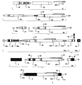
- FIG. 2 is an assembly process diagram showing the assembly process of the mechanical pencil 1 of the present embodiment when viewed from the side.
- the mechanical pencil 1 includes a front barrel 21, a packing 211, a tip pipe 212, a rear barrel 22, a middle barrel 23, a fitting barrel 24, a writing core gripping and feeding mechanism 25, and a cushion spring. 25a, a tip 26, a screwing portion pressing spring 26a, an eraser receiving base 271, an eraser 272, an outer shaft cylinder 3, and a knock set 4.
- a front barrel 21 a packing 211, a tip pipe 212, a rear barrel 22, a middle barrel 23, a fitting barrel 24, a writing core gripping and feeding mechanism 25, and a cushion spring.
- 25a a tip 26, a screwing portion pressing spring 26a, an eraser receiving base 271, an eraser 272, an outer shaft cylinder 3, and a knock set 4.
- the rear barrel 22, the middle barrel 23, and the fitting barrel 24 are all substantially cylindrical members, and the shaft barrel assembly of the mechanical pencil 1 is composed of the front barrel 21 and the outer barrel 3 described later. Is configured.
- the rear end of the fitting cylinder 24 is press-fitted from the front end side of the rear barrel 22 and is connected to the rear barrel 22 so as to be relatively rotatable.
- the front end portion of the fitting cylinder 24 is press-fitted and fitted from the rear end side of the middle shaft cylinder 23 so as to be integrally rotatable with the middle shaft cylinder 23.
- the rear barrel 22 and the middle barrel 23 can be rotated relative to each other.
- a pair of cams 241 disposed at an interval of 180 ° in the circumferential direction is formed so as to protrude from the inner peripheral surface in the inner diameter direction.
- Each of the cams 241 has a cam tip that protrudes toward the tip, and the cam tip contacts and follows a cam surface formed on a sleeve 251 described in detail later. The adjustment of the cushion stroke by the cam surfaces formed on the cam 241 and the sleeve 251 will be described in detail later.
- the writing core gripping / feeding mechanism 25 grips the writing core 9 in which the graphite is formed in an elongated shape so that writing can be performed, and the writing core 9 can be sent forward according to the knocking operation of the user.
- the front end of the rear barrel assembly constituted by the rear barrel 22, the middle barrel 23 and the fitting barrel 24 with the cushion spring 25a which is a compression coil spring, assembled on the outer periphery of the rear portion thereof. It is inserted from the side.
- the cushion spring 25a is compressed in the axial direction between the rear barrel 22 and the writing core gripping / feeding mechanism 25, and biases the writing core gripping / feeding mechanism 25 forward with a predetermined load.
- the cushion mechanism of the mechanical pencil 1 having the cushion spring 25a is a mechanism that relieves excessive writing pressure applied to the writing core 9 at the time of writing by urging the writing core gripping / feeding mechanism 25 forward so as to be retractable. It is.
- the cushion mechanism of the mechanical pencil 1 according to the present embodiment can adjust the distance (cushion stroke) that the writing core gripping and feeding mechanism 25 can move backward from zero (no relaxation) to a predetermined amount, as will be described in detail later. This makes it possible to adjust the magnitude of the writing pressure to be relaxed.
- the tip cylinder 21 is formed in a substantially cylindrical shape having a tapered tip, and a packing 211 having a central hole for clamping the sent writing core 9 with a predetermined pressure is assembled inside the tip. .
- a tip pipe 21b that guides the writing core 9 is press-fitted and fixed to the tip of the front barrel 21 so as to have a predetermined protruding amount.
- a screw portion 210b is formed on the outer periphery of the rear end portion of the front end barrel 21, and the front end portion 21 of the front end barrel 21 covers the front end portion of the writing core gripping and feeding mechanism 25. Are screwed into corresponding screw portions formed on the inner periphery of the front end portion.
- the tip 26 is configured as a movable member in the mechanical pencil 1 of the present embodiment so as to be movable in the axial direction so that the user can arbitrarily adjust the protruding amount of the tip pipe 21b from the tip of the tip 26.
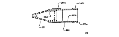
- the tip 26 is formed in a substantially cylindrical shape having a tapered tip, and as shown in FIG. 10, a screw portion 260b is formed on the inner periphery of the rear end.
- the screw portion 260b of the tip tool 26 is configured such that the tip tool 26 covers the outer periphery of the front end portion of the front shaft tube 21 in a state where the screw-joining portion pressing spring 26a that is a compression coil spring is assembled to the outer periphery of the front shaft tube 21.
- a screw portion 211a (see FIG. 7) formed on the outer peripheral surface of the front shaft cylinder 21 is screwed.
- the distal end pipe 21 b press-fitted and fixed to the distal end portion of the front barrel 21 can be projected and retracted through an opening formed at the distal end of the distal end tool 26.
- the user can adjust the protruding length of the tip pipe 21b from the tip of the tip 26 by adjusting the position of the tip 26 with respect to the tip barrel 21.
- An elastomer O-ring 26b formed in an annular shape is attached to the outer periphery of the tip 26. As will be described later in detail, the O-ring 26b is attached between the tip 26 and the outer shaft cylinder 3, and is configured to press the tip 26 inward in the radial direction.
- the O-ring 26b can be formed of any material having elasticity that can press the tip 26 in the radial direction.
- the eraser base 271 is formed in a substantially cylindrical shape, and as shown in S4a, the eraser 272 is inserted into the rear part thereof, and the front part thereof is inserted into the rear end part of the rear shaft cylinder 22 to hold the writing core. It is attached to the rear end of the delivery mechanism 25.
- the outer diameter of the rear portion of the eraser pedestal 271 is formed smaller than the inner diameter of the rear portion of the rear barrel 22, and the knock bar 41 is assembled between the inner peripheral surface of the rear barrel 22 and the outer peripheral surface of the eraser pedestal 271. A gap is formed.
- the knock set 4 has a knock bar 41 formed in a substantially cylindrical shape, a display seal 42 for the user to select and display the hardness of the writing core 9, and a display selected by the user from one side of the side. It has a display ring 43 formed in a substantially cylindrical shape having an opening so that a part of the seal 42 can be seen and fitted to the rear end of the knock bar 41 and closed at the rear end. The user rotates the display ring 43 fitted to the rear end portion of the knock bar 41 in the circumferential direction, so that the display hardness of the arbitrary writing core 9 described on the display sticker 42 attached to the rear portion of the knock bar 41 is obtained. , Can be selectively exposed to the outside and displayed.
- the outer shaft cylinder 3 is a member formed in a substantially cylindrical shape assembled to the outer periphery of the tip tool 26 and the middle shaft cylinder 23, and the outer peripheral surface of the outer shaft cylinder 3 is knurled so that the user can easily grasp the shaft cylinder.
- a screw portion is formed on the inner peripheral surface of the rear end portion of the outer shaft tube 3, and the outer shaft tube 3 covers the rear portions of the front shaft tube 21 and the tip tool 26 and the outer periphery of the middle shaft tube 23.
- the screw portion on the inner peripheral surface of the rear end portion is screwed with the screw portion formed on the outer peripheral surface of the rear portion of the middle shaft cylinder 23.
- the outer shaft tube 3 and the rear shaft tube 22 screwed together with the middle shaft tube 23 can be relatively rotated for the operation of adjusting a cushion stroke, which will be described in detail later.
- the knock bar 41 of the knock set 4 is detachably attached to the rear outer peripheral surface of the eraser receiving base 271 protruding from the rear end of the rear barrel 22. When the knock set 4 is removed, the eraser 272 assembled to the eraser receiving base 271 can be used.
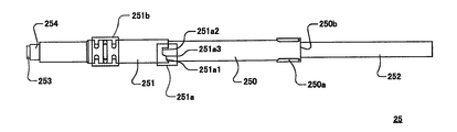
- FIG. 3 is a diagram showing the writing core gripping and feeding mechanism as viewed from the side.
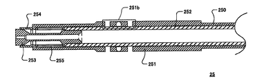
- FIG. 4 is an enlarged cross-sectional view showing the writing core gripping and feeding mechanism shown in FIG. 3 by cutting it along a plane including its central axis.
- FIG. 5 is a cross-sectional view showing the rear barrel cut by a plane including its central axis.
- FIG. 6 is a cross-sectional view of the rear barrel of the present embodiment cut along a plane perpendicular to the central axis and viewed from the front.
- the writing core gripping and feeding mechanism 25 has a cylindrical central part 250, a sleeve having an outer diameter larger than the central part 250 and integrally formed with the central part 250. 251, a writing core pipe 252 that is assembled inside the central portion 250 and accommodates the writing core 9, a chuck 253 that can hold and feed the writing core 9 forward, a chuck ring 254 that is assembled to the chuck 253, and a sleeve 251. And a chuck spring 255, which is a compressed coil spring.
- the chuck spring 255 urges the writing core pipe 252 in which the rear end portion of the chuck 253 is press-fitted backward with respect to the sleeve 251.
- the front end portion of the chuck 253 is fitted to the chuck ring 254 with the chuck ring 254 sandwiched between the front end surface of the sleeve 251 and is pressed radially inward by the front end portion of the chuck ring 254 thus fitted.
- the chuck ring 254 comes into contact with the shaft cylinder, and the chuck 253 moves forward relative to the chuck ring 254 against the biasing force of the chuck spring 255.
- the fitting between the chuck 253 and the chuck ring 254 is released, and the grip of the writing core 9 is released.
- the chuck 253 and the chuck ring 254 leave the fed writing core 9 in the front while being held by being held by the packing 211 at the position where the writing core 9 is fed out. Is moved backward by the urging force of the chuck spring 255 and grips the position behind the writing core 9.
- the sleeve 251 includes a meshing portion 251a constituting a cushion mechanism capable of adjusting the cushion stroke in the mechanical pencil 1 of the present embodiment, and a set for eliminating an assembly error in the axial direction of the central portion 250 and the sleeve 251 with respect to the shaft cylinder. And an attached error absorbing portion 251b.
- cushion stroke adjustment in the cushion mechanism of the mechanical pencil 1 of the present embodiment will be described.
- the sleeve 251 is formed with a pair of meshing portions 251a at an interval of 180 ° in the circumferential direction on the rear end surface of the sleeve 251.
- the pair of meshing portions 251a of the sleeve 251 is formed to face a pair of cams 241 (see FIG. 1) formed on the inner peripheral surface of the fitting cylinder 24.
- Each of the meshing portions 251a constitutes a cam surface facing the cam 241, and includes a first portion 251a1 which is a rear cam surface, a second portion 251a2 which is a front cam surface, a first portion 251a1 and a second portion. And a third portion 251a3 which is an intermediate cam surface which is located between and connected to 251a2.
- an engaging portion 250a that protrudes radially outward and engages with the inner peripheral surface of the rear barrel 22 is formed.
- the rear shaft cylinder 22 and the writing core gripping and feeding mechanism 25 are configured to rotate as a unit. For this reason, when the rear shaft cylinder 22 is rotated relative to the middle shaft cylinder 23 and the fitting cylinder 24, the writing core gripping and feeding mechanism 25 has the cam 241 on its inner peripheral surface along with the rear shaft cylinder 22. It is comprised so that relative rotation with respect to the formed fitting cylinder 24 and the center axis
- the cushion stroke is configured to be zero when the tip of the cam 241 comes into contact with the first portion 251a1 of the meshing portion 251a. In this case, the cushion spring 25a is not compressed and deformed.
- the cushion stroke becomes maximum, and the cushion spring 25a can be compressed and deformed by the allowable cushion stroke.
- the cushion stroke is performed with an intermediate cushion stroke between zero and the maximum.
- it is comprised so that a user can adjust a cushion stroke arbitrarily.
- the rear barrel 22 will be further described with reference to FIGS.
- the rear barrel 22 is formed to protrude radially inward over the entire circumference of the inner peripheral surface thereof, and has a locking portion 221 that locks the rear end portion of the cushion spring 25a.
- connection portions 222 that are a plurality of annular grooves extending in the circumferential direction are formed in order to engage the fitting cylinder 24 in a relatively rotatable manner.
- the writing core gripping and feeding mechanism 25 and the rear barrel 22 are configured to rotate together with the engaging portion 250 a of the writing core gripping and feeding mechanism 25.
- Engaged portions 223 that are a plurality of grooves extending in the axial direction to be joined are formed.
- the outer shaft cylinder 3 screwed to the middle shaft cylinder 23 is rotated relative to the rear shaft cylinder 22 so that the user can adjust the contact position of the tip of the cam 241 in the meshing portion 251a.
- the user can adjust the retractable distance (cushion stroke) of the writing core gripping and sending mechanism 25.
- the user of the mechanical pencil 1 can adjust the maximum load (cushion operating load) of the writing pressure applied to the writing core 9 according to the hardness of the writing core 9 or the material of the paper surface.
- FIG. 7 is a view showing the front shaft cylinder 21 of the present embodiment as viewed from the side.
- FIG. 8 is a cross-sectional view showing the tip cylinder 21 of FIG. 7 cut along a plane including the central axis.
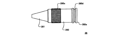
- FIG. 9 is a view showing the tip 26 of the present embodiment as viewed from the side.
- FIG. 10 is a cross-sectional view showing the tip 26 of FIG. 9 cut along a plane including the central axis.
- the front shaft cylinder 21 is formed in a substantially cylindrical shape having a plurality of portions having different outer diameters.
- the plurality of portions are roughly classified, and the front barrel 21 has a first diameter portion 210, a second diameter portion 211, a third diameter portion 212, and a fourth diameter portion 213 in order from the rear end side.
- the first diameter portion 210 is formed to have the largest outer diameter in the front shaft cylinder 21, and the rear end portion of the threaded portion pressing spring 26 a is engaged on the outer peripheral surface of the first diameter portion 210 so as to protrude radially outward over the entire circumference. It has a flange 210a that stops.
- the second diameter portion 211 is formed to have an outer diameter smaller than that of the first diameter portion 210, and a screw for screwing the outer peripheral surface of the front barrel 21 and the inner peripheral surface of the tip tool 26 onto the outer peripheral surface thereof.
- a portion 211a is formed.
- the third diameter portion 212 is formed to have an outer diameter dimension A that will be described in detail later, which is smaller than the outer diameter of the second diameter portion 211.
- the fourth diameter portion 213 has the smallest outer diameter in the tip barrel 21 and has a tip that is tapered, and a hole 213a into which the tip pipe 21b can be press-fitted is formed at the tip.
- the tip 26 has a body portion 260 formed in a substantially cylindrical shape and a conical portion 261 formed in a substantially conical cylindrical shape in order from the rear end side.
- the conical portion 261 has a through-hole at which the tip pipe 21b of the front barrel 21 protrudes and appears.
- a screw portion 260 b is formed on the inner peripheral surface of the body portion 260, and is screwed into the screw portion 211 a on the outer peripheral surface of the second diameter portion 211 of the front barrel 21. Further, when the tip tool 26 is disposed at the most rearward position with respect to the tip barrel 21, the inner peripheral surface of the tip tool 26 is close to the outer peripheral surface of the tip barrel 21 in the axial direction and the radial direction.
- the internal space 260a is formed so as to abut.
- the inner diameter a of the internal space 260a in front of the body 260 of the tip 26 is formed to a size that substantially contacts with the outer diameter A (see FIG. 7) of the third diameter 212 of the front barrel 21. .
- a grip portion 260c that is knurled over the entire circumference is formed so that the user can easily rotate the tip tool 26 in the circumferential direction.
- an assembly groove 260d to which the O-ring 26b (see FIGS. 1 and 2) is assembled is formed to extend all around.
- the front and rear walls of the assembly groove 260d are formed as inclined surfaces that are inclined so that the groove width becomes wider toward the outside in the radial direction. If comprised in this way, the pressing force which presses the tip tool 26 to radial direction inner side by the O-ring 26b assembled
- the O-ring 26b can be brought into contact with the outer peripheral surface of the tip 26 so as to have a plurality of contact portions, and the pressing force of the plurality of contact portions can be made uniform. Therefore, a highly reliable contact state can be obtained, and the O-ring 26b can be used for a longer period without applying excessive stress.
- the amount of protrusion from the tip of the tip 26 of the tip pipe 21b of the tip barrel 21 can be adjusted by the tip barrel 21, the tip 26, the screwing portion pressing spring 26a and the O-ring 26b.
- a possible adjustment mechanism is configured.
- the tip tool 26 screwed into the tip barrel 21 can be operated so that the user can grip the grip portion 260c of the tip tool 26 and rotate it relative to the tip barrel 21 around the central axis. By this adjustment operation, it is possible to adjust the relative arrangement position of the tip tool 26 with respect to the tip shaft cylinder 21 in the axial direction while maintaining the screw engagement between the tip cylinder 21 and the tip tool 26.
- the tip pipe 21b fixed to the tip of the tip barrel 21 can be protruded from the tip of the tip tool 26 by an amount desired by the user, or adjusted so that it is completely accommodated in the tip tool 26. it can.
- the adjustment position of the tip tool 26 adjusted by the user is maintained by the O-ring 26b coming into contact with and pressing the tip tool 26 from the radially outer side over the entire circumference.
- the holding force with which the O-ring 26b holds the tip tool 26 in a predetermined adjustment position does not differ depending on the adjustment position of the tip tool 26.
- the screwing part press spring 26a may urge the screwing part so that the tip cylinder 21 and the tip tool 26 may space apart from each other in the axial direction.
- the threaded portion of the threaded portion 211a of the front shaft tube 21 and the thread of the threaded portion 260b of the tool 26 are pressed by pressing the threaded portion of the front tube 21 and the tool 26 in the axial direction by the threaded portion pressing spring 26a.
- the mountain is in close contact with each other, and the frictional force of the contact surface of the screwing portion can be increased.
- the pressing force in the axial direction of the screwing portion pressing spring 26a of the present embodiment is a pressing force with such a magnitude that the user cannot perceive the difference in the rotational operation force of the tip tool 26 due to the difference in the adjustment position of the tip tool 26. Configured to be. If comprised in this way, the retention strength which hold
- the threaded portion pressing spring 26a may be any one that urges the threaded portion of the threaded portion 211a of the front shaft cylinder 21 and the threaded portion of the threaded portion 260b of the tip 26 to be in close contact with each other.
- the amount of protrusion of the tip pipe 21b of the mechanical pencil 1 from the tip 26 is adjusted.
- the amount of protrusion of the tip of the ballpoint pen from the nose cone, etc. may be applied similarly to an arbitrary adjustment mechanism that adjusts the arrangement position in the axial direction of an arbitrary movable member provided in an arbitrary writing instrument.
- the pressing member exemplified as the O-ring 26b may be any member that presses the movable member in the radial direction, and the pressing direction presses in the outer radial direction even if it presses in the inner radial direction. It may be a thing.
Landscapes
- Mechanical Pencils And Projecting And Retracting Systems Therefor, And Multi-System Writing Instruments (AREA)
Abstract
Description
21 先軸筒
25 筆記芯把持送出機構
26 先具
26b O‐リング
Claims (5)
- 軸線方向に移動可能な可動部材の配置位置を調整する位置調整機構を備え、
前記位置調整機構は前記可動部材を径方向から押圧する押圧部材を有する
ことを特徴とする筆記具。 - 前記押圧部材はエラストマー材料で環状に形成され、その内周面又は外周面が前記可動部材に当接して径方向に押圧する、請求項1に記載の筆記具。
- 前記押圧部材が組み付けられる溝が周方向の全周に延在して形成され、該溝の前後壁は、径方向外側に向かうに従って溝幅が幅広となるように傾斜した傾斜面として形成される、請求項2に記載の筆記具。
- 前記可動部材は前記位置調整機構に螺合され、該螺合の螺合部を軸線方向に付勢する螺合部押圧ばねを更に備える、請求項1乃至請求項3のいずれか一項に記載の筆記具。
- 筆記芯を把持及び送り出すことができる筆記芯把持送出機構と、
前記筆記芯把持送出機構を収容すると共に相互に相対回転する一及び他の軸筒と、
前記筆記芯把持送出機構を先端側に向けて付勢するクッションばねとを更に備え、
前記一及び他の軸筒の一方は他方に向けて突出するカムを有し、該一及び他の軸筒の他方は軸線方向において該カムと対向するカム面を有し、該カム面は、前記クッションばねの可動量をゼロとする第1部分と、該クッションばねの可動量を最大量とする第2部分と、該第1部分と第2部分とを接続する中間部分として形成される第3部分とを有する、請求項1乃至請求項4のいずれか一項に記載の筆記具。
Priority Applications (5)
| Application Number | Priority Date | Filing Date | Title |
|---|---|---|---|
| US16/482,678 US20200009899A1 (en) | 2017-02-22 | 2018-02-21 | Writing implement |
| JP2019501366A JP6840831B2 (ja) | 2017-02-22 | 2018-02-21 | 筆記具 |
| EP18757170.8A EP3587139A4 (en) | 2017-02-22 | 2018-02-21 | INSTRUMENT FOR WRITING |
| KR1020197021198A KR20190113780A (ko) | 2017-02-22 | 2018-02-21 | 필기구 |
| CN201880011442.2A CN110290931A (zh) | 2017-02-22 | 2018-02-21 | 书写用具 |
Applications Claiming Priority (2)
| Application Number | Priority Date | Filing Date | Title |
|---|---|---|---|
| JP2017031086 | 2017-02-22 | ||
| JP2017-031086 | 2017-02-22 |
Publications (1)
| Publication Number | Publication Date |
|---|---|
| WO2018155476A1 true WO2018155476A1 (ja) | 2018-08-30 |
Family
ID=63254418
Family Applications (1)
| Application Number | Title | Priority Date | Filing Date |
|---|---|---|---|
| PCT/JP2018/006158 Ceased WO2018155476A1 (ja) | 2017-02-22 | 2018-02-21 | 筆記具 |
Country Status (7)
| Country | Link |
|---|---|
| US (1) | US20200009899A1 (ja) |
| EP (1) | EP3587139A4 (ja) |
| JP (1) | JP6840831B2 (ja) |
| KR (1) | KR20190113780A (ja) |
| CN (1) | CN110290931A (ja) |
| TW (1) | TW201831340A (ja) |
| WO (1) | WO2018155476A1 (ja) |
Cited By (1)
| Publication number | Priority date | Publication date | Assignee | Title |
|---|---|---|---|---|
| JP2022010698A (ja) * | 2020-06-29 | 2022-01-17 | ぺんてる株式会社 | シャープペンシル |
Families Citing this family (2)
| Publication number | Priority date | Publication date | Assignee | Title |
|---|---|---|---|---|
| JP7491927B2 (ja) | 2019-07-25 | 2024-05-28 | 株式会社パイロットコーポレーション | 出没式筆記具 |
| EP4146205A4 (en) | 2020-05-05 | 2024-05-29 | Nuvalent, Inc. | HETEROAROMATIC MACROCYCLIC ETHERS AS CHEMOTHERAPEUTIC AGENTS |
Citations (6)
| Publication number | Priority date | Publication date | Assignee | Title |
|---|---|---|---|---|
| JPS54179248U (ja) * | 1978-06-08 | 1979-12-18 | ||
| US5018891A (en) * | 1989-07-10 | 1991-05-28 | Kotobuko & Co., Ltd. | Writing instrument with eraser dispenser |
| JPH05162492A (ja) * | 1991-12-16 | 1993-06-29 | Kotobuki:Kk | シャープペンシルのクッション機構 |
| JP2003291586A (ja) * | 2002-04-04 | 2003-10-15 | Suemine Takahashi | 改良型ノック式シャープペンシル |
| JP2004223820A (ja) | 2003-01-22 | 2004-08-12 | Suemine Takahashi | 改良型ノック式シャープペンシル |
| JP2012076399A (ja) * | 2010-10-05 | 2012-04-19 | Pilot Corporation | 出没式シャープペンシル |
Family Cites Families (7)
| Publication number | Priority date | Publication date | Assignee | Title |
|---|---|---|---|---|
| JPS59126687U (ja) * | 1983-02-15 | 1984-08-25 | オ−ト株式会社 | シヤ−プペンシル |
| JPS59157877U (ja) * | 1983-04-07 | 1984-10-23 | 堂元 芳治 | クツシヨン付きシヤ−プペンシル |
| JP2505735Y2 (ja) * | 1990-05-18 | 1996-07-31 | 株式会社壽 | 回転式シャ―プペンシル |
| US7806615B1 (en) * | 2007-10-26 | 2010-10-05 | Mitsubishi Pencil Co., Ltd. | Mechanical pencil |
| US7850380B2 (en) * | 2007-10-26 | 2010-12-14 | Mitsubishi Pencil Co., Ltd. | Mechanical pencil |
| JP5711047B2 (ja) * | 2011-05-30 | 2015-04-30 | ゼブラ株式会社 | シャープペンシル |
| JP6293539B2 (ja) * | 2014-03-20 | 2018-03-14 | 株式会社壽 | シャープペンシル |
-
2017
- 2017-11-02 TW TW106137989A patent/TW201831340A/zh unknown
-
2018
- 2018-02-21 WO PCT/JP2018/006158 patent/WO2018155476A1/ja not_active Ceased
- 2018-02-21 EP EP18757170.8A patent/EP3587139A4/en not_active Withdrawn
- 2018-02-21 KR KR1020197021198A patent/KR20190113780A/ko not_active Withdrawn
- 2018-02-21 US US16/482,678 patent/US20200009899A1/en not_active Abandoned
- 2018-02-21 CN CN201880011442.2A patent/CN110290931A/zh not_active Withdrawn
- 2018-02-21 JP JP2019501366A patent/JP6840831B2/ja active Active
Patent Citations (6)
| Publication number | Priority date | Publication date | Assignee | Title |
|---|---|---|---|---|
| JPS54179248U (ja) * | 1978-06-08 | 1979-12-18 | ||
| US5018891A (en) * | 1989-07-10 | 1991-05-28 | Kotobuko & Co., Ltd. | Writing instrument with eraser dispenser |
| JPH05162492A (ja) * | 1991-12-16 | 1993-06-29 | Kotobuki:Kk | シャープペンシルのクッション機構 |
| JP2003291586A (ja) * | 2002-04-04 | 2003-10-15 | Suemine Takahashi | 改良型ノック式シャープペンシル |
| JP2004223820A (ja) | 2003-01-22 | 2004-08-12 | Suemine Takahashi | 改良型ノック式シャープペンシル |
| JP2012076399A (ja) * | 2010-10-05 | 2012-04-19 | Pilot Corporation | 出没式シャープペンシル |
Non-Patent Citations (1)
| Title |
|---|
| See also references of EP3587139A4 * |
Cited By (2)
| Publication number | Priority date | Publication date | Assignee | Title |
|---|---|---|---|---|
| JP2022010698A (ja) * | 2020-06-29 | 2022-01-17 | ぺんてる株式会社 | シャープペンシル |
| JP7415228B2 (ja) | 2020-06-29 | 2024-01-17 | ぺんてる株式会社 | シャープペンシル |
Also Published As
| Publication number | Publication date |
|---|---|
| JP6840831B2 (ja) | 2021-03-10 |
| TW201831340A (zh) | 2018-09-01 |
| EP3587139A1 (en) | 2020-01-01 |
| US20200009899A1 (en) | 2020-01-09 |
| JPWO2018155476A1 (ja) | 2019-12-19 |
| EP3587139A4 (en) | 2020-11-25 |
| CN110290931A (zh) | 2019-09-27 |
| KR20190113780A (ko) | 2019-10-08 |
Similar Documents
| Publication | Publication Date | Title |
|---|---|---|
| US10500891B2 (en) | Mechanical pencil | |
| WO2018155476A1 (ja) | 筆記具 | |
| US20200062022A1 (en) | Writing instrument holder and writing instrument holder set | |
| US20150202692A1 (en) | Chuck | |
| JP6806794B2 (ja) | シャープペンシル | |
| KR20180114929A (ko) | 공구용 척 및 공구 유지 방법 및 공구 분리 방법 | |
| CN108698433B (zh) | 活心铅笔 | |
| JP5933203B2 (ja) | 筆記具用軸筒 | |
| WO2020050247A1 (ja) | 文房具、化粧料容器及び化粧品 | |
| JP4753761B2 (ja) | 筆記具の軸筒 | |
| JP7261032B2 (ja) | シャープペンシルユニット及び出没式筆記具 | |
| JP6976844B2 (ja) | 筆記具 | |
| JP6968695B2 (ja) | 筆記具 | |
| JP5781881B2 (ja) | ノック式シャープペンシル | |
| US290291A (en) | Pencil-holder | |
| JPH077198Y2 (ja) | 芯出可変機構付きシャープペンシル | |
| JP4896769B2 (ja) | 筆記具の軸筒 | |
| US1204800A (en) | Handpiece for dental machines. | |
| JP2017030197A (ja) | 芯繰出具 | |
| JP6608271B2 (ja) | 筆記具 | |
| JP2025007329A (ja) | シャープペンシル | |
| JP2025007336A (ja) | シャープペンシル | |
| JP3188602U (ja) | シャープペンシル | |
| JP2008207501A (ja) | 装飾構造 | |
| JP2016159555A (ja) | 筆記具用部品の接続構造及び該接続構造を具備した筆記具並びに該筆記具の製造方法 |
Legal Events
| Date | Code | Title | Description |
|---|---|---|---|
| 121 | Ep: the epo has been informed by wipo that ep was designated in this application |
Ref document number: 18757170 Country of ref document: EP Kind code of ref document: A1 |
|
| ENP | Entry into the national phase |
Ref document number: 20197021198 Country of ref document: KR Kind code of ref document: A |
|
| ENP | Entry into the national phase |
Ref document number: 2019501366 Country of ref document: JP Kind code of ref document: A |
|
| NENP | Non-entry into the national phase |
Ref country code: DE |
|
| ENP | Entry into the national phase |
Ref document number: 2018757170 Country of ref document: EP Effective date: 20190923 |