WO2018155477A1 - Procédé de soudage au laser - Google Patents
Procédé de soudage au laser Download PDFInfo
- Publication number
- WO2018155477A1 WO2018155477A1 PCT/JP2018/006162 JP2018006162W WO2018155477A1 WO 2018155477 A1 WO2018155477 A1 WO 2018155477A1 JP 2018006162 W JP2018006162 W JP 2018006162W WO 2018155477 A1 WO2018155477 A1 WO 2018155477A1
- Authority
- WO
- WIPO (PCT)
- Prior art keywords
- irradiation
- laser
- welding
- laser beam
- irradiating
- Prior art date
- Legal status (The legal status is an assumption and is not a legal conclusion. Google has not performed a legal analysis and makes no representation as to the accuracy of the status listed.)
- Ceased
Links
Images


Classifications
-
- B—PERFORMING OPERATIONS; TRANSPORTING
- B23—MACHINE TOOLS; METAL-WORKING NOT OTHERWISE PROVIDED FOR
- B23K—SOLDERING OR UNSOLDERING; WELDING; CLADDING OR PLATING BY SOLDERING OR WELDING; CUTTING BY APPLYING HEAT LOCALLY, e.g. FLAME CUTTING; WORKING BY LASER BEAM
- B23K26/00—Working by laser beam, e.g. welding, cutting or boring
- B23K26/20—Bonding
- B23K26/21—Bonding by welding
- B23K26/24—Seam welding
- B23K26/244—Overlap seam welding
-
- B—PERFORMING OPERATIONS; TRANSPORTING
- B23—MACHINE TOOLS; METAL-WORKING NOT OTHERWISE PROVIDED FOR
- B23K—SOLDERING OR UNSOLDERING; WELDING; CLADDING OR PLATING BY SOLDERING OR WELDING; CUTTING BY APPLYING HEAT LOCALLY, e.g. FLAME CUTTING; WORKING BY LASER BEAM
- B23K26/00—Working by laser beam, e.g. welding, cutting or boring
- B23K26/20—Bonding
- B23K26/21—Bonding by welding
-
- B—PERFORMING OPERATIONS; TRANSPORTING
- B23—MACHINE TOOLS; METAL-WORKING NOT OTHERWISE PROVIDED FOR
- B23K—SOLDERING OR UNSOLDERING; WELDING; CLADDING OR PLATING BY SOLDERING OR WELDING; CUTTING BY APPLYING HEAT LOCALLY, e.g. FLAME CUTTING; WORKING BY LASER BEAM
- B23K1/00—Soldering, e.g. brazing, or unsoldering
- B23K1/005—Soldering by means of radiant energy
- B23K1/0056—Soldering by means of radiant energy soldering by means of beams, e.g. lasers, electron beams [EB]
-
- H—ELECTRICITY
- H01—ELECTRIC ELEMENTS
- H01M—PROCESSES OR MEANS, e.g. BATTERIES, FOR THE DIRECT CONVERSION OF CHEMICAL ENERGY INTO ELECTRICAL ENERGY
- H01M8/00—Fuel cells; Manufacture thereof
- H01M8/02—Details
-
- H—ELECTRICITY
- H01—ELECTRIC ELEMENTS
- H01M—PROCESSES OR MEANS, e.g. BATTERIES, FOR THE DIRECT CONVERSION OF CHEMICAL ENERGY INTO ELECTRICAL ENERGY
- H01M8/00—Fuel cells; Manufacture thereof
- H01M8/02—Details
- H01M8/0202—Collectors; Separators, e.g. bipolar separators; Interconnectors
-
- Y—GENERAL TAGGING OF NEW TECHNOLOGICAL DEVELOPMENTS; GENERAL TAGGING OF CROSS-SECTIONAL TECHNOLOGIES SPANNING OVER SEVERAL SECTIONS OF THE IPC; TECHNICAL SUBJECTS COVERED BY FORMER USPC CROSS-REFERENCE ART COLLECTIONS [XRACs] AND DIGESTS
- Y02—TECHNOLOGIES OR APPLICATIONS FOR MITIGATION OR ADAPTATION AGAINST CLIMATE CHANGE
- Y02E—REDUCTION OF GREENHOUSE GAS [GHG] EMISSIONS, RELATED TO ENERGY GENERATION, TRANSMISSION OR DISTRIBUTION
- Y02E60/00—Enabling technologies; Technologies with a potential or indirect contribution to GHG emissions mitigation
- Y02E60/30—Hydrogen technology
- Y02E60/50—Fuel cells
Definitions
- the present invention relates to a laser welding method for welding a workpiece by irradiating the workpiece with a laser beam in a state where a plurality of workpieces are stacked.
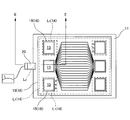
- weld seal line 14 by marking a weld portion by welding as L 1 ).
- the weld seal portion 14 is indicated by a dotted line
- the rubber seal portion (rubber seal line) 16 by the gasket 15 is indicated by a solid line.
- reference numeral 17 denotes a hydrogen flow channel
- reference numeral 18 denotes an oxygen flow channel
- reference numeral 19 denotes a cooling water flow channel.
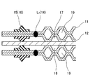
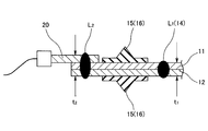
- the weld seal portion 14 is formed by laser welding a pair of separators (first and second workpieces) 11 and 12, and the laser welded pair of separators 11, 11, technique of bonding are known in same laser welding accessory (third work) 20 (showing a welded portion by the laser welding by symbol L 2) to 12.
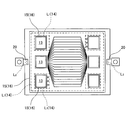
- the parts for voltage monitoring are drawn in FIG. 7 and FIG. 8 as the accessory parts 20, the kind of parts is not particularly limited, and may be, for example, a part for positioning between separators as shown in FIG. .
- weld L 2 of the separator 11 and 12 and the attachment 20 3 parts 11,12,20 total thickness t 2 is to increase by (the thickness by the pair of separators 11 and 12 as t 1, t 1 ⁇ t 2 ) , it is necessary to perform welding at a higher energy density than welds L 1 between the pair of separators 11 and 12 (heat input).
- Weld L 2 of the separator 11 and 12 and the attachment 20 is preferably through welding 3 parts 11,12,20 in order to stabilize the quality, however, occur, such as open hole in 3 parts 11,12,20 It is desirable not to.
- the welding seal portion 14 is formed by laser welding the pair of separators 11 and 12, and the accessory 20 is similarly joined to the laser welded pair of separators 11 and 12 by the laser welding.
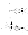
- a 500 W small output irradiation apparatus and a 750 W large output irradiation apparatus both not shown
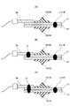
- first, as shown in FIG. 10A a pair of 500 W small output irradiation apparatus is used.
- the separators 11 and 12 are welded at the welding portion L 1 , and then, as shown in FIG. 10 (B), a pair of separators 11 and 12 and accessories 20 are welded to the welding portion L 2 using a 750 W high power irradiation device. Method of welding.
- welding of a pair of separators 11 and 12 and welding of a pair of separators 11 and 12 and accessories 20 are performed in the same process using the same laser irradiation apparatus performed, when welding the fitment 20 and the latter of the pair of separators 11 and 12, be added to the energy density of the plate thickness increments by folding the laser irradiated weld L 2 along the predetermined welding line accessory 20 , 3 parts 11, 12 and 20 can be through-welded.
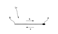
- welds L 2 of the accessory 20 for example a folded laser irradiation along a weld L 2 of accessory 20 here certain welding line, constant weld extending from point A to point B
- point A is the beginning of the irradiation, irradiate from point A to point B (arrow a), then turn around at point B and irradiate from point B to point A (arrow b), with point A being the end of the irradiation, there will be two (one round trip) irradiations along a substantially constant weld line.
- the energy density (heat input amount) at the beginning (end) and the end (end) of the laser irradiation may be higher than those of the other portions, for convenience of machine control, etc. There are many, and thus, the amount of penetration is large. Therefore, as shown in the figure, when the start and end portions of the irradiation overlap on the plane and are set at the same position (point A), the energy density to be irradiated becomes very high, and as a result, There is a possibility that a problem may occur.
- the present invention provides a laser welding method in which the irradiation energy density does not become very high by multiple times of laser irradiation, and thus no defect such as perforation occurs in the work.
- the purpose is to
- a laser welding method is a laser welding method for welding a workpiece by irradiating the workpiece with a laser beam in a state where a plurality of workpieces are stacked, along a certain welding line
- the irradiation energy can be dispersed by shifting the irradiation position at the end of the irradiation.
- the laser welding method of the present invention in the laser welding method of welding the workpieces by irradiating the workpieces with the laser beams in a state where a plurality of workpieces are stacked, a folded laser beam is irradiated along a certain welding line
- the irradiation energy can be dispersed by shifting the irradiation position at the start and end of the irradiation.
- the first irradiation for irradiating the laser beam to weld the first work and the second work, and the laser for welding the third work to the first and second works welded by the first irradiation The second irradiation to irradiate the beam is performed in the same process using the same irradiation equipment, and when the second irradiation is performed, the folded laser beam is irradiated along a certain welding line, and at this time, the beginning of the irradiation and It is characterized in that the irradiation energy can be dispersed by shifting the irradiation position at the end portion.
- the same direction is provided a plurality of times along a certain welding line.
- the irradiation energy can be dispersed by shifting the irradiation position between the start ends and / or the end parts of the irradiation.
- the first irradiation for irradiating the laser beam to weld the first work and the second work, and the laser for welding the third work to the first and second works welded by the first irradiation The second irradiation for irradiating the beam is performed in the same process using the same irradiation equipment, and when performing the second irradiation, the laser beam is irradiated in the same direction a plurality of times along a fixed welding line, It is characterized in that the irradiation energy can be dispersed by shifting the irradiation position between the start ends of the irradiation and / or between the end parts of the irradiation.
- first and second workpieces are separators for a fuel cell
- the third workpiece is an attached component attached to the separator for a fuel cell.
- the irradiation energy when irradiating the laser beam multiple times along a certain welding line, the irradiation energy can be dispersed by shifting the irradiation position at the end of the irradiation, so the irradiation energy density is very high at the end of the irradiation. None get high. Therefore, it is possible to prevent the occurrence of a defect such as a hole in the work due to a plurality of times of laser irradiation which causes the irradiation energy density to be extremely high.
- FIG. 7 A plan view showing another example of a fuel cell component to be worked by the laser welding method according to the prior art Process explanatory drawing of the laser welding method which concerns on a prior art example Explanatory drawing of the laser irradiation position in the laser welding method which concerns on another prior art example
- the present invention includes the following embodiments.
- a separate part accessory part
- the welding of the seal line portion and the welding of the separate part are performed in the same process (same equipment), and laser welding is performed on the same welding line multiple times when welding the separate part to the separator.
- the laser welding method according to the embodiment is to join by welding a pair of fuel cell separators 11 and 12 as the work (welding object), ie, Welded seal portion is formed by laser welding around the outer peripheral portion of the anode separator (first work) 11 and the cathode separator (second work) 12 and the manifold 13 (the weld portion by this laser welding is indicated by a symbol L 1 ) (Welding seal line) 14 is formed, and accessory parts (third work) 20 are similarly laser welded to the pair of laser-welded separators 11 and 12 (a weld by this laser welding is indicated by a symbol L 2 ) It is supposed to be joined.
- the component for voltage monitoring is drawn as the accessory component 20, the type of component is not particularly limited, and may be, for example, a component for positioning between separators as shown in FIG.
- the weld seal portion 14 is shown by a dotted line
- the rubber seal portion (rubber seal line) 16 by the gasket 15 is shown by a solid line.
- welding of the pair of separators 11 and 12 and the pair of separators 11 and 12 are performed as a method in which welding of the accessories 20 is not performed separately from welding of the separators 11 and 12.
- Welding of the attachment part 20 is performed in the same process using the same laser irradiation apparatus (not shown).
- the accessory 20 is superimposed on the welded pair of separators 11 and 12, and the separators 11, 12 and accessory 20 are irradiated with a laser beam (second irradiation) Form a weld L 2 of the attachment 20.
- the separator 11, 12 in welding the attachment 20 is folded to laser irradiation along a weld L 2 of the accessory 20 at a constant welding line.
- Is to be folded laser irradiation along a certain welding line welds L 2 of accessory 20 here, but will perform irradiation of 2 times along a certain welding line (one round trip), as described above If the start and end portions of the irradiation overlap on the plane and are set at the same position, the energy density to be irradiated becomes very high, which may cause problems such as hole formation.
- the irradiation energy when irradiating the laser beam a plurality of times along a certain welding line, can be dispersed by shifting the irradiation position at the end of the irradiation, specifically
- the irradiation energy when irradiating a folded laser beam along a fixed welding line, can be dispersed by shifting the irradiation position at the start and end of the irradiation.
- the specific procedure is as follows.
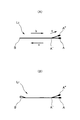
- First scan of second irradiation (forward scan, FIG. 2 (B)).
- FIG. 3 (A) and the welded portion L 2 of accessory 20, when irradiating a laser along a predetermined welding line extending from point A to point B, the starting end of the irradiation point A, It irradiates from A point to B point (arrow a).
- Second scan of second irradiation (backward scanning, FIG. 2 (C)). Then, as shown in the same figure, turn back at point B and irradiate from point B to point A (arrow b), but the direction of irradiation at point A '(branch) before (immediately) reaching point A
- the branch line of the welding line is set (arrow c) by changing, and the A '' point close to the A point but different from the A point is the end of the irradiation.
- the irradiation energy density may be raised not only at the start and end portions of the irradiation but also at the turn-back portion (point B) of the irradiation, the turn-up of the irradiation as shown in FIG.
- the welding line may be inverted into a U-shape or a substantially U-shape.
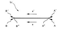
- the irradiation energy can be dispersed by shifting the irradiation position between the start ends and / or the end parts of the irradiation.
- Second scan of the second irradiation ... Then, as shown in the figure, the second scan is irradiated, but at this time, the point A 'close to the point A but different from the point A is taken as the start edge of the irradiation, and it is close to the point B but the point B And the point B 'of a different position from the end of the irradiation (arrow a').
- the irradiation line of the first scan and the irradiation line of the second scan overlap at points A ′ ′ and B ′ ′ after point A ′ ′ that is close to points A and A ′ but different from points A and A ′. Branches after point B ′ ′ which is close but different from point B and point B ′.
Landscapes
- Engineering & Computer Science (AREA)
- Physics & Mathematics (AREA)
- Optics & Photonics (AREA)
- Mechanical Engineering (AREA)
- Sustainable Development (AREA)
- Chemical & Material Sciences (AREA)
- Chemical Kinetics & Catalysis (AREA)
- Electrochemistry (AREA)
- General Chemical & Material Sciences (AREA)
- Sustainable Energy (AREA)
- Life Sciences & Earth Sciences (AREA)
- Plasma & Fusion (AREA)
- Manufacturing & Machinery (AREA)
- Laser Beam Processing (AREA)
- Fuel Cell (AREA)
Abstract
Priority Applications (5)
| Application Number | Priority Date | Filing Date | Title |
|---|---|---|---|
| KR1020197023103A KR102444098B1 (ko) | 2017-02-24 | 2018-02-21 | 레이저 용접 방법 |
| US16/478,594 US11491579B2 (en) | 2017-02-24 | 2018-02-21 | Laser welding method |
| EP18758380.2A EP3587024B1 (fr) | 2017-02-24 | 2018-02-21 | Procédé de soudage au laser |
| JP2019501367A JP6735898B2 (ja) | 2017-02-24 | 2018-02-21 | レーザ溶接方法 |
| CN201880008741.0A CN110234460B (zh) | 2017-02-24 | 2018-02-21 | 激光焊接方法 |
Applications Claiming Priority (2)
| Application Number | Priority Date | Filing Date | Title |
|---|---|---|---|
| JP2017032872 | 2017-02-24 | ||
| JP2017-032872 | 2017-02-24 |
Publications (1)
| Publication Number | Publication Date |
|---|---|
| WO2018155477A1 true WO2018155477A1 (fr) | 2018-08-30 |
Family
ID=63253295
Family Applications (1)
| Application Number | Title | Priority Date | Filing Date |
|---|---|---|---|
| PCT/JP2018/006162 Ceased WO2018155477A1 (fr) | 2017-02-24 | 2018-02-21 | Procédé de soudage au laser |
Country Status (6)
| Country | Link |
|---|---|
| US (1) | US11491579B2 (fr) |
| EP (1) | EP3587024B1 (fr) |
| JP (1) | JP6735898B2 (fr) |
| KR (1) | KR102444098B1 (fr) |
| CN (1) | CN110234460B (fr) |
| WO (1) | WO2018155477A1 (fr) |
Cited By (1)
| Publication number | Priority date | Publication date | Assignee | Title |
|---|---|---|---|---|
| CN113146029A (zh) * | 2021-04-19 | 2021-07-23 | 山西奥斯腾科技有限责任公司 | 将焊接、修复、检测集成于一体的激光头 |
Families Citing this family (2)
| Publication number | Priority date | Publication date | Assignee | Title |
|---|---|---|---|---|
| CN111604594A (zh) * | 2020-05-27 | 2020-09-01 | 湖北亿纬动力有限公司 | 一种电池盖板的焊接工艺以及电池 |
| KR102409185B1 (ko) * | 2020-08-21 | 2022-06-16 | 주식회사 보림파워텍 | Sofc 스택용 분리판과 셀프레임 접합방법 |
Citations (4)
| Publication number | Priority date | Publication date | Assignee | Title |
|---|---|---|---|---|
| JP2002172484A (ja) * | 2000-12-01 | 2002-06-18 | Komatsu Ltd | 接合方法 |
| JP2005106527A (ja) * | 2003-09-29 | 2005-04-21 | Toyoda Mach Works Ltd | 圧力センサ及びその製造方法 |
| JP2009183970A (ja) | 2008-02-05 | 2009-08-20 | Nissan Motor Co Ltd | レーザ溶接方法、レーザ溶接装置、および溶接部材 |
| JP2012135794A (ja) * | 2010-12-27 | 2012-07-19 | Suzuki Motor Corp | レーザ重ね溶接方法 |
Family Cites Families (22)
| Publication number | Priority date | Publication date | Assignee | Title |
|---|---|---|---|---|
| US6906281B2 (en) * | 2003-03-03 | 2005-06-14 | Dana Corporation | Method for laser welding of metal |
| US6646225B1 (en) * | 2003-04-02 | 2003-11-11 | General Motors Corporation | Method of joining galvanized steel parts using lasers |
| JP5343307B2 (ja) * | 2006-05-16 | 2013-11-13 | 日産自動車株式会社 | 燃料電池スタックおよび燃料電池セパレータ並びにその製造方法 |
| DE102010018377B4 (de) * | 2010-04-26 | 2013-09-12 | Labom Meß- und Regeltechnik GmbH | Funktionsbauteil wie Druckmittler mit einer Metallfolie aus Sonderwerkstoff, Verfahren zum Anschweißen einer Metallfolie aus Sonderwerkstoff sowie Laserstrahlschweißeinrichtung hierfür |
| JP5495118B2 (ja) * | 2010-04-28 | 2014-05-21 | スズキ株式会社 | 亜鉛めっき鋼板のレーザ重ね溶接方法 |
| JP2012170989A (ja) * | 2011-02-22 | 2012-09-10 | Suzuki Motor Corp | レーザ重ね溶接方法 |
| JP5880032B2 (ja) * | 2011-12-27 | 2016-03-08 | トヨタ自動車株式会社 | レーザー溶接方法 |
| KR20140080754A (ko) * | 2012-12-17 | 2014-07-01 | 현대자동차주식회사 | 레이저 용접방법 |
| JP6194233B2 (ja) * | 2013-01-08 | 2017-09-06 | 株式会社ジャパンディスプレイ | 表示装置の製造方法 |
| WO2015104781A1 (fr) * | 2014-01-10 | 2015-07-16 | パナソニックIpマネジメント株式会社 | Appareil de soudage au laser et procédé de soudage au laser |
| WO2015129231A1 (fr) | 2014-02-25 | 2015-09-03 | パナソニックIpマネジメント株式会社 | Procédé de soudage au laser |
| US10195688B2 (en) * | 2015-01-05 | 2019-02-05 | Johnson Controls Technology Company | Laser welding system for a battery module |
| JP6135691B2 (ja) * | 2015-02-18 | 2017-05-31 | トヨタ自動車株式会社 | レーザ溶接方法 |
| US10835993B2 (en) * | 2015-08-05 | 2020-11-17 | Panasonic Intellectual Property Management Co., Ltd. | Laser welding method |
| US10828720B2 (en) * | 2015-10-13 | 2020-11-10 | The Curators Of The University Of Missouri | Foil-based additive manufacturing system and method |
| US10118249B2 (en) * | 2015-10-15 | 2018-11-06 | GM Global Technology Operations LLC | Laser beam welding with a spiral weld path having a first order of continuity |
| CN108367391B (zh) * | 2015-11-06 | 2020-03-20 | 通用汽车环球科技运作有限责任公司 | 叠置的铝工件的激光点焊 |
| US10512986B2 (en) * | 2016-02-15 | 2019-12-24 | Ford Global Technologies, Llc | Laser welding process |
| CN109219498B (zh) * | 2016-03-16 | 2021-10-01 | 通用汽车环球科技运作有限责任公司 | 叠置的金属工件的快速远程激光焊接 |
| US10195689B2 (en) * | 2016-07-11 | 2019-02-05 | GM Global Technology Operations LLC | Laser welding of overlapping metal workpieces assisted by varying laser beam parameters |
| US20200114469A1 (en) * | 2017-02-09 | 2020-04-16 | GM Global Technology Operations LLC | Method for laser welding light metal workpieces that include a surface oxide coating |
| US10888955B2 (en) * | 2017-02-28 | 2021-01-12 | GM Global Technology Operations LLC | Avoiding hot cracks during laser welding of a workpiece stack-up assembly of aluminum alloy workpieces |
-
2018
- 2018-02-21 CN CN201880008741.0A patent/CN110234460B/zh active Active
- 2018-02-21 EP EP18758380.2A patent/EP3587024B1/fr active Active
- 2018-02-21 JP JP2019501367A patent/JP6735898B2/ja active Active
- 2018-02-21 WO PCT/JP2018/006162 patent/WO2018155477A1/fr not_active Ceased
- 2018-02-21 KR KR1020197023103A patent/KR102444098B1/ko active Active
- 2018-02-21 US US16/478,594 patent/US11491579B2/en active Active
Patent Citations (4)
| Publication number | Priority date | Publication date | Assignee | Title |
|---|---|---|---|---|
| JP2002172484A (ja) * | 2000-12-01 | 2002-06-18 | Komatsu Ltd | 接合方法 |
| JP2005106527A (ja) * | 2003-09-29 | 2005-04-21 | Toyoda Mach Works Ltd | 圧力センサ及びその製造方法 |
| JP2009183970A (ja) | 2008-02-05 | 2009-08-20 | Nissan Motor Co Ltd | レーザ溶接方法、レーザ溶接装置、および溶接部材 |
| JP2012135794A (ja) * | 2010-12-27 | 2012-07-19 | Suzuki Motor Corp | レーザ重ね溶接方法 |
Non-Patent Citations (1)
| Title |
|---|
| See also references of EP3587024A4 |
Cited By (1)
| Publication number | Priority date | Publication date | Assignee | Title |
|---|---|---|---|---|
| CN113146029A (zh) * | 2021-04-19 | 2021-07-23 | 山西奥斯腾科技有限责任公司 | 将焊接、修复、检测集成于一体的激光头 |
Also Published As
| Publication number | Publication date |
|---|---|
| US11491579B2 (en) | 2022-11-08 |
| KR20190121756A (ko) | 2019-10-28 |
| JPWO2018155477A1 (ja) | 2019-11-07 |
| EP3587024C0 (fr) | 2025-04-30 |
| KR102444098B1 (ko) | 2022-09-15 |
| EP3587024A4 (fr) | 2020-03-11 |
| CN110234460B (zh) | 2021-06-29 |
| JP6735898B2 (ja) | 2020-08-05 |
| US20200030912A1 (en) | 2020-01-30 |
| EP3587024A1 (fr) | 2020-01-01 |
| CN110234460A (zh) | 2019-09-13 |
| EP3587024B1 (fr) | 2025-04-30 |
Similar Documents
| Publication | Publication Date | Title |
|---|---|---|
| JP6593280B2 (ja) | 平角線のレーザ溶接方法 | |
| WO2018155477A1 (fr) | Procédé de soudage au laser | |
| US8610026B2 (en) | Laser welding method | |
| US20160368078A1 (en) | Method of welding workpieces together while minimizing distortion | |
| JP2009241116A (ja) | 金属材の溶接方法及び金属材の接合体 | |
| JP2016030280A (ja) | 金属箔のレーザ溶接方法及び装置 | |
| CN105880829B (zh) | 激光焊接方法 | |
| JP6335602B2 (ja) | レーザ溶接方法 | |
| JP2016207412A (ja) | レーザ溶接物及び電池のレーザ溶接良否判定方法 | |
| JP2014147962A (ja) | 部材接合方法、部材接合構造、および継手管 | |
| JP6149887B2 (ja) | 溶接方法 | |
| EP3378591B1 (fr) | Procédé de soudage laser et dispositif de soudage laser | |
| JP7535721B2 (ja) | レーザ加工方法およびレーザ加工装置 | |
| JP4232024B2 (ja) | 溶接ビード構造及び溶接方法 | |
| JP2017030004A (ja) | 配管溶接方法および溶接組立て構造 | |
| KR20120077094A (ko) | 코팅강판의 접합방법 | |
| JP2004283883A (ja) | 開先形状とその溶接方法 | |
| JP2008109753A (ja) | 被覆剥離方法 | |
| JP2024157413A (ja) | レーザ溶接方法およびレーザ溶接システム | |
| JP2008137011A (ja) | レーザ溶接方法 | |
| JP2010169030A (ja) | プロペラ羽根の製造方法、プロペラ羽根及び送風機 | |
| Ream | High-speed laser welding of fuel cell metals | |
| JP2017035721A (ja) | レーザ溶接継手 |
Legal Events
| Date | Code | Title | Description |
|---|---|---|---|
| 121 | Ep: the epo has been informed by wipo that ep was designated in this application |
Ref document number: 18758380 Country of ref document: EP Kind code of ref document: A1 |
|
| ENP | Entry into the national phase |
Ref document number: 2019501367 Country of ref document: JP Kind code of ref document: A |
|
| ENP | Entry into the national phase |
Ref document number: 20197023103 Country of ref document: KR Kind code of ref document: A |
|
| NENP | Non-entry into the national phase |
Ref country code: DE |
|
| ENP | Entry into the national phase |
Ref document number: 2018758380 Country of ref document: EP Effective date: 20190924 |
|
| WWG | Wipo information: grant in national office |
Ref document number: 2018758380 Country of ref document: EP |