WO2018155603A1 - Dispositif de commande de freinage pour véhicule - Google Patents
Dispositif de commande de freinage pour véhicule Download PDFInfo
- Publication number
- WO2018155603A1 WO2018155603A1 PCT/JP2018/006600 JP2018006600W WO2018155603A1 WO 2018155603 A1 WO2018155603 A1 WO 2018155603A1 JP 2018006600 W JP2018006600 W JP 2018006600W WO 2018155603 A1 WO2018155603 A1 WO 2018155603A1
- Authority
- WO
- WIPO (PCT)
- Prior art keywords
- vehicle
- state
- stop
- range
- braking force
- Prior art date
- Legal status (The legal status is an assumption and is not a legal conclusion. Google has not performed a legal analysis and makes no representation as to the accuracy of the status listed.)
- Ceased
Links
Images


Classifications
-
- B—PERFORMING OPERATIONS; TRANSPORTING
- B60—VEHICLES IN GENERAL
- B60T—VEHICLE BRAKE CONTROL SYSTEMS OR PARTS THEREOF; BRAKE CONTROL SYSTEMS OR PARTS THEREOF, IN GENERAL; ARRANGEMENT OF BRAKING ELEMENTS ON VEHICLES IN GENERAL; PORTABLE DEVICES FOR PREVENTING UNWANTED MOVEMENT OF VEHICLES; VEHICLE MODIFICATIONS TO FACILITATE COOLING OF BRAKES
- B60T7/00—Brake-action initiating means
- B60T7/12—Brake-action initiating means for automatic initiation; for initiation not subject to will of driver or passenger
- B60T7/122—Brake-action initiating means for automatic initiation; for initiation not subject to will of driver or passenger for locking of reverse movement
-
- B—PERFORMING OPERATIONS; TRANSPORTING
- B60—VEHICLES IN GENERAL
- B60T—VEHICLE BRAKE CONTROL SYSTEMS OR PARTS THEREOF; BRAKE CONTROL SYSTEMS OR PARTS THEREOF, IN GENERAL; ARRANGEMENT OF BRAKING ELEMENTS ON VEHICLES IN GENERAL; PORTABLE DEVICES FOR PREVENTING UNWANTED MOVEMENT OF VEHICLES; VEHICLE MODIFICATIONS TO FACILITATE COOLING OF BRAKES
- B60T8/00—Arrangements for adjusting wheel-braking force to meet varying vehicular or ground-surface conditions, e.g. limiting or varying distribution of braking force
- B60T8/17—Using electrical or electronic regulation means to control braking
- B60T8/171—Detecting parameters used in the regulation; Measuring values used in the regulation
-
- B—PERFORMING OPERATIONS; TRANSPORTING
- B60—VEHICLES IN GENERAL
- B60T—VEHICLE BRAKE CONTROL SYSTEMS OR PARTS THEREOF; BRAKE CONTROL SYSTEMS OR PARTS THEREOF, IN GENERAL; ARRANGEMENT OF BRAKING ELEMENTS ON VEHICLES IN GENERAL; PORTABLE DEVICES FOR PREVENTING UNWANTED MOVEMENT OF VEHICLES; VEHICLE MODIFICATIONS TO FACILITATE COOLING OF BRAKES
- B60T7/00—Brake-action initiating means
- B60T7/12—Brake-action initiating means for automatic initiation; for initiation not subject to will of driver or passenger
-
- B—PERFORMING OPERATIONS; TRANSPORTING
- B60—VEHICLES IN GENERAL
- B60W—CONJOINT CONTROL OF VEHICLE SUB-UNITS OF DIFFERENT TYPE OR DIFFERENT FUNCTION; CONTROL SYSTEMS SPECIALLY ADAPTED FOR HYBRID VEHICLES; ROAD VEHICLE DRIVE CONTROL SYSTEMS FOR PURPOSES NOT RELATED TO THE CONTROL OF A PARTICULAR SUB-UNIT
- B60W30/00—Purposes of road vehicle drive control systems not related to the control of a particular sub-unit, e.g. of systems using conjoint control of vehicle sub-units
- B60W30/18—Propelling the vehicle
- B60W30/18009—Propelling the vehicle related to particular drive situations
- B60W30/18109—Braking
- B60W30/18118—Hill holding
-
- B—PERFORMING OPERATIONS; TRANSPORTING
- B60—VEHICLES IN GENERAL
- B60T—VEHICLE BRAKE CONTROL SYSTEMS OR PARTS THEREOF; BRAKE CONTROL SYSTEMS OR PARTS THEREOF, IN GENERAL; ARRANGEMENT OF BRAKING ELEMENTS ON VEHICLES IN GENERAL; PORTABLE DEVICES FOR PREVENTING UNWANTED MOVEMENT OF VEHICLES; VEHICLE MODIFICATIONS TO FACILITATE COOLING OF BRAKES
- B60T2201/00—Particular use of vehicle brake systems; Special systems using also the brakes; Special software modules within the brake system controller
- B60T2201/06—Hill holder; Start aid systems on inclined road
Definitions
- the present invention relates to a vehicle braking control device that controls a braking force applied to a vehicle.
- the shift range that is the range of the shift device of the vehicle is a travel range (for example, a forward range).
- a non-traveling range for example, a neutral range
- the number of pulses acquired from the detection signal output from the wheel speed sensor in a situation where it is determined that the vehicle is stopped is equal to or greater than the specified number. It can be determined that the vehicle is starting to move downhill. Therefore, in such a case, the braking force on the vehicle is increased by executing the braking force increasing process. Thereby, the movement to the downhill side of the vehicle on a slope can be suppressed.
- a vehicle traveling on a slope may be stopped, and then the shift range may be changed to move the vehicle in a direction (reverse direction) opposite to the traveling direction of the vehicle (for example, the forward direction). is there.
- the driver of the vehicle changes the shift range from the forward range to the reverse range or neutral range when the vehicle traveling on the uphill road stops. May try to move.
- the vehicle braking control device for solving the above-described problem shifts from a pre-stop movement state in which the vehicle travels in either the forward direction or the reverse direction to a stop state in which the vehicle stops,
- the other direction which is a shift range for driving the vehicle in either the forward direction or the backward direction from the range for the one direction which is a shift range for driving the vehicle in the one direction.
- a determination unit for determining whether or not the range has been changed to the neutral range, and the range or neutral for the other direction from the range for the one direction when moving from the pre-stop movement state to the stop state.
- the braking device of the vehicle When the vehicle is moved from a stopped state to a post-stop moving state in a state where it is determined that the range has been changed to the range, the braking device of the vehicle is activated. Therefore and a, and a brake control unit for implementing the braking force increasing process for increasing the braking force to the vehicle.
- the braking control unit is in a situation where the determination unit determines that the range for the one direction has been changed from the range for the other direction or the neutral range when the transition from the pre-stop movement state to the stop state is performed. Even when the vehicle is moved from the stop state to the post-stop movement state, the braking force is applied on the condition that the vehicle movement direction in the post-stop movement state is opposite to the vehicle movement direction in the pre-stop movement state.
- the limiting process is executed not to perform the increasing process or to reduce the increase amount of the braking force in the braking force increasing process.
- the vehicle traveling on a slope upside is stopped by applying a braking force
- the range for the one direction from the range for the one direction or
- the neutral range is changed
- the driving force for driving the vehicle to the upper side of the slope is not applied to the vehicle.
- the vehicle may start to move downhill (the other direction).
- the braking force increasing process is not performed, that is, the braking force for the wheel is not increased, or the limiting process for reducing the increase amount of the braking force in the braking force increasing process is performed. For this reason, the movement of the vehicle on the downhill side (the other direction) is hardly suppressed.
- the schematic block diagram which shows a part of vehicle provided with the braking control apparatus of the vehicle in 1st Embodiment.
- the action figure which shows a mode that the vehicle has stopped on the uphill road.
- the action figure which shows a mode that the vehicle is moving to the downhill side on an uphill road.
- FIG. 1 schematically shows a part of a vehicle including the braking control device 110 of the present embodiment.
- a driving torque output from an engine 21, which is an example of a power source of the vehicle is transmitted to the wheels 11 through the transmission 22 and the differential gear 23, the wheels 11 rotate. It is supposed to run by doing.
- the transmission 22 has a torque converter 221. Therefore, when the driving range is selected as the shift range which is the range selected by the shift device 12 and the engine 21 is operating, the accelerator operation is not performed by the driver of the vehicle. Also, creep torque is input to the wheels 11, that is, driving force is applied to the vehicle.
- D range in FIG. 1 is a forward range
- R range is a backward range
- N range in FIG. 1 is a “neutral range” and is a range for blocking torque transmission from the engine 21 to the wheels 11.
- P range in FIG. 1 is a “parking range” and is a parking range.
- the vehicle includes a braking mechanism 31 provided for each wheel 11 and a braking device 35 connected to the wheel cylinder 311 of each braking mechanism 31 via a pipe 32.
- the braking mechanism 31 includes a rotating body 312 that rotates integrally with the wheel 11, and a friction material 313 that moves in a direction toward and away from the rotating body 312.
- the force for pressing the friction material 313 against the rotating body 312, that is, the braking force applied to the wheel 11 can be adjusted by adjusting the WC pressure Pwc that is the hydraulic pressure in the wheel cylinder 311.
- a braking operation member 361 such as a brake pedal is connected to the hydraulic pressure generating device 36 of the braking device 35.
- the MC pressure Pmc which is the hydraulic pressure in the master cylinder 362 provided in the hydraulic pressure generator 36, increases as the amount of operation of the braking operation member 361 increases, that is, as the braking force requested by the driver increases.
- the hydraulic pressure generator 36 supplies brake fluid corresponding to the operation amount into the wheel cylinder 311 through the brake actuator 37 when the brake operation member 361 is operated. Therefore, the braking device 35 can increase the braking force on the vehicle as the braking force request value BPRq, which is a braking force requested by the driver, which correlates with the operation amount of the braking operation member 361 increases.
- the braking actuator 37 of the braking device 35 is configured so that the differential pressure between the master cylinder 362 and the wheel cylinder 311 can be adjusted. That is, the brake actuator 37 can increase the WC pressure Pwc even when the brake operation member 361 is not operated.
- the vehicle is provided with a plurality of control devices 120, 130, and 140 in addition to the braking control device 110.
- a hydraulic pressure sensor 201 that detects the MC pressure Pmc and a wheel speed sensor 202 that detects a wheel speed VW that is the rotation speed of the wheel 11 are electrically connected to the braking control device 110.
- the braking control device 110 controls the braking actuator 37 of the braking device 35.
- Various sensors necessary for controlling the engine 21 are electrically connected to the engine control device 120, and the engine control device 120 controls the engine 21.
- the shift device 12 is electrically connected to the transmission control device 130, and the transmission control device 130 controls the transmission device 22.
- the vehicle has an automatic driving control device 140 in which an application for automatic driving and an application for automatic vehicle speed control such as adaptive cruise control are installed.
- These control devices 110, 120, 130, and 140 can transmit and receive various types of information to and from each other via the communication bus 101.
- the braking control device 110 includes a determination unit 111 and a braking control unit 112 as functional units for adjusting the braking force applied to the vehicle when the vehicle stops.
- the determination unit 111 determines whether or not the shift range has been changed when the vehicle travels from the pre-stop movement state to the stop state in which the vehicle stops. Specifically, when the vehicle is moving forward, the determination unit 111 is changed from the D range to the R range or the N range when the vehicle moves in the forward direction from the pre-stop moving state to the stopped state. Determine whether or not. Thus, when the moving direction of the vehicle in the pre-stop moving state is the forward direction, the forward direction corresponds to “one direction” and the reverse direction corresponds to “the other direction”. Of the shift ranges, the D range corresponds to “a range for one direction”, and the R range corresponds to “a range for the other direction”.
- the determination unit 111 determines whether the R range is changed to the D range or the N range when the vehicle moves in the backward direction from the pre-stop moving state to the stopped state. judge.
- the reverse direction corresponds to “one direction”
- the forward direction corresponds to “the other direction”.
- the R range corresponds to “a range for one direction”
- the D range corresponds to “a range for the other direction”.
- the braking control unit 112 is a stop in which the vehicle moves from the stop state after the shift range is changed to the R range or the N range when the vehicle moves in the forward direction from the pre-stop movement state to the stop state.
- a braking force increasing process for increasing the braking force on the vehicle by the operation of the braking actuator 37 is performed.
- the braking control unit 112 moves after stopping from the stop state after the shift range is changed to the D range or the N range when the vehicle moves in the reverse direction from the pre-stop movement state to the stop state.
- the braking force increasing process is performed.
- the braking control unit 112 shifts from the stop state to the post-stop movement state after the shift range is changed in this way, the braking force increasing process is not performed when a condition described later is satisfied. That is, the braking force on the vehicle is not increased.
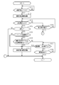
- the determination unit 111 determines whether or not the vehicle is stopped, that is, whether or not the vehicle is moved from the pre-stop moving state to the stopped state. . Specifically, the determination unit 111 calculates the vehicle body speed VS of the vehicle based on the wheel speed VW of the wheel 11 detected by the wheel speed sensor 202. When the calculated vehicle body speed VS is equal to or lower than the stop determination speed VSTh, the determination unit 111 determines that the vehicle is stopped, that is, determines that the vehicle has moved from the pre-stop movement state to the stop state.
- step S11 If it cannot be determined that the vehicle is stopped (step S11: NO), the determination in step S11 is repeated until it can be determined that the vehicle is stopped. On the other hand, when it can be determined that the vehicle is stopped (step S11: YES), the process proceeds to the next step S12.
- step S ⁇ b> 12 the braking control unit 112 performs a braking force holding process for holding the braking force on the vehicle at the magnitude at which it is determined that the vehicle is stopped.
- the operation amount of the braking operation member 361 is increased under the condition where the braking force holding process is being performed, the operation amount of the braking operation member 361 is increased under the condition where the braking force holding process is not being performed. As in the case, the braking force on the vehicle is increased.
- the determination unit 111 determines whether or not the vehicle has started moving, that is, whether or not the vehicle has shifted from the stopped state to the post-stop moving state. Specifically, the determination unit 111 determines that the vehicle has started to move when it detects that the wheel 11 is rotating based on the wheel speed VW detected by the wheel speed sensor 202, that is, a stopped state. It is determined that the state has shifted to the moving state after stopping.
- step S13 If it cannot be determined that the vehicle has started moving (step S13: NO), the process proceeds to the next step S14.
- step S ⁇ b> 14 the braking control unit 112 determines whether or not an end condition for executing this processing routine is satisfied.
- the end condition includes that the shift range is changed to the P range. If the end condition is not satisfied (step S14: NO), the process proceeds to step S13 described above. On the other hand, when the termination condition is satisfied (step S14: YES), this processing routine is terminated.
- step S15 the determination unit 111 determines whether or not the current moving direction of the vehicle, that is, the moving direction of the vehicle in the post-stop moving state is opposite to the moving direction of the vehicle in the pre-stop moving state. Determined.
- step S15: NO the moving direction of the vehicle in the post-stop moving state is the same direction as the moving direction of the vehicle in the pre-stop moving state (step S15: NO).
- step S16 the determination unit 111 determines whether or not the shift range has been changed. Specifically, when the moving direction of the vehicle in the pre-stop movement state is the forward direction, and the shift range at the time of transition from the pre-stop movement state to the stop state is the D range, the determination unit 111 When the shift range is the R range or the N range, it is determined that the shift range has been changed. On the other hand, when the current shift range is the D range, it is not determined that the shift range has been changed.
- the determination unit 111 determines that the current shift range is While it is determined that the shift range has been changed when the range is the D range or the N range, it is not determined that the shift range has been changed when the current shift range is the R range.
- step S16 If it cannot be determined that the shift range has been changed (step S16: NO), the process proceeds to the next step S17. Even if it is not possible to determine that the shift range has been changed, if the moving direction of the vehicle in the moving state after stopping is opposite to the moving direction of the vehicle in the moving state before stopping, the vehicle is kept in the stopped state. Although the driver desires this, there is a possibility that the stop state of the vehicle cannot be maintained because the braking force on the vehicle is small. Therefore, in step S17, a braking force increasing process is performed by the braking control unit 112. Thereafter, this processing routine is terminated.
- step S16 when it can be determined in step S16 that the shift range has been changed (YES), the process proceeds to the next step S18. Then, in the next step S18, whether or not the braking force request value BPRq, which is the braking force requested by the driver, is equal to or greater than the stop holding braking force BPTh that is set as a braking force that can maintain the stopped state. It is determined by the braking control unit 112. Specifically, the braking control unit 112 calculates the braking force request value BPRq so that the higher the MC pressure Pmc correlated with the operation amount of the braking operation member 361, the larger the value. Further, the braking control unit 112 uses the map shown in FIG. 2 to derive the stop holding braking force BPTh based on the road surface gradient ⁇ where the vehicle is located and the selected shift range.
- the solid line in FIG. 2 represents the relationship between the road surface gradient ⁇ and the stop holding braking force BPTh when the selected shift range is the N range. Further, the broken line in FIG. 2 represents the relationship between the road surface gradient ⁇ and the stop holding braking force BPTh when the selected shift range is the D range. In addition, the alternate long and short dash line in FIG. 2 represents the relationship between the road surface gradient ⁇ and the stop holding braking force BPTh when the selected shift range is the R range.
- the stop holding braking force BPTh when the N range is selected is the smallest when the gradient ⁇ is equal to the first gradient ⁇ 1.
- the road surface can be regarded as a flat road.
- the stop holding braking force BPTh gradually increases as the difference between the gradient ⁇ and the first gradient ⁇ 1 increases.
- the stop holding braking force BPTh when the D range is selected is the smallest when the gradient ⁇ is equal to the second gradient ⁇ 2.
- the second gradient ⁇ 2 is larger than the first gradient ⁇ 1.
- the road surface can be regarded as an uphill road.
- the stop holding braking force BPTh gradually increases as the difference between the gradient ⁇ and the second gradient ⁇ 2 increases.
- the stop holding braking force BPTh when the R range is selected is the smallest when the gradient ⁇ is equal to the third gradient ⁇ 3.
- the third gradient ⁇ 3 is smaller than the first gradient ⁇ 1.
- the road surface can be regarded as a downhill road.
- the stop holding braking force BPTh gradually increases as the difference between the gradient ⁇ and the third gradient ⁇ 3 increases.
- step S18 when the braking force request value BPRq is equal to or larger than the stop holding braking force BPTh in step S18 (YES), the process proceeds to step S17 described above. That is, when the vehicle starts to move even though the braking force request value BPRq is equal to or greater than the stop holding braking force BPTh, the actual braking force for the vehicle is smaller than the braking force request value BPRq, so that the vehicle is kept stopped. It cannot be determined that the vehicle has started to move. Therefore, in such a case, the braking control unit 112 performs a braking force increase process.
- step S18 when the braking force request value BPRq is less than the stop holding braking force BPTh (step S18: NO), the process proceeds to the next step S19.
- the driver in order to allow the transition from the stop state to the post-stop movement state, the driver can determine that there is a possibility that the amount of operation of the braking operation member 361 is intentionally reduced.
- step S19 it is determined whether or not the specified time has elapsed from the time when the movement of the vehicle is detected, that is, the time when the vehicle has moved from the stopped state to the moved state after stopping, that is, whether or not the specified period TRM has ended. It is determined by the control unit 112.
- Vehicle operation for running the vehicle here refers to a braking operation that reduces the amount of operation of the braking operation member 361, a steering operation that operates the steering wheel of the vehicle, and an accelerator operation that operates the accelerator pedal. Contains.
- step S20 the braking operation member 361 determines whether or not the vehicle operation as described above is being performed. And when vehicle operation is not performed (step S20: NO), a process transfers to step S19 mentioned above. On the other hand, when the vehicle operation is being performed (step S20: YES), this processing routine is terminated without executing the braking force increasing process. That is, when the above vehicle operation is performed during the specified period TRM, the braking force on the vehicle is not increased.
- step S19 the process proceeds to step S17 described above. That is, if no vehicle operation is performed during the specified period TRM, the vehicle is moving in a direction opposite to the moving direction of the vehicle in the pre-stop movement state, as requested by the driver. It can be judged that it is not. Therefore, in such a case, the braking control unit 112 performs a braking force increase process.
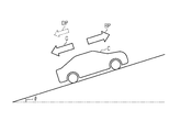
- the vehicle C When the engine 21 is operating in a state where the shift range is the D range, the vehicle C is moving up the slope, that is, in the forward direction.
- the braking force BP is applied to the vehicle C by the operation of the braking operation member 361 by the driver, the vehicle C decelerates and stops. That is, the vehicle C shifts from the pre-stop movement state to the stop state.
- the gravity G applied to the vehicle C acts on the downhill side, that is, in the backward direction.
- the braking force BP and the driving force DP act on the vehicle C as forces that restrict the movement of the vehicle C to the downhill side.
- the sum of the braking force BP and the driving force DP is balanced with the gravity G.
- the driving force DP becomes equal to “0”.
- the vehicle C starts to move downward. That is, the vehicle C shifts from the stopped state to the moved state after stopping.
- the driving force is used as a force for moving the vehicle C downward.
- DP acts on the vehicle C.
- the vehicle C starts to move downward. That is, the vehicle C shifts from the stopped state to the moved state after stopping.
- At least one of the braking operation, the accelerator operation, and the steering operation that reduces the operation amount of the braking operation member 361 by the time the specified period TRM starting from the start of the downward movement of the vehicle C is completed.
- the braking force increasing process is not performed. That is, when such a vehicle operation is performed during the specified period TRM, it can be determined that the vehicle C is in a state desired by the driver, so that the braking force BP against the vehicle C can be determined. Is not increased. As a result, the movement of the vehicle C downward is continued. Therefore, it becomes possible to move the vehicle C that has moved up the hill to the downhill side by changing the shift range while the vehicle C is stopped.
- the vehicle C moves downhill. It cannot be determined that the state is desired. Therefore, in the present embodiment, the braking force BP for the vehicle C is increased by performing the braking force increasing process. Therefore, the movement of the vehicle C to the downhill side can be suppressed.
- the braking force request value BPRq is equal to or greater than the stop holding braking force BPTh
- the actual braking force BP for the vehicle C is smaller than the braking force request value BPRq.
- the braking force BP for the vehicle C is increased by performing the braking force increasing process. Therefore, the movement of the vehicle C to the downhill side can be suppressed.
- the braking force request value BPRq is less than the stop holding braking force BPTh, it is determined that the movement of the vehicle C downhill is desired by the driver. can do. Therefore, if the vehicle operation as described above is performed by the end of the specified period TRM, the braking force increasing process is not performed. Thereby, since the braking force BP for the vehicle C is not increased, the vehicle C can be moved downward.
- the vehicle C When the engine 21 is operating in a state where the shift range is the R range, the vehicle C is moving on the uphill road, that is, in the backward direction.
- the braking force BP is applied to the vehicle C by the operation of the braking operation member 361 by the driver, the vehicle C decelerates and stops. That is, the vehicle C shifts from the pre-stop movement state to the stop state.
- the gravity G applied to the vehicle C acts on the hill side.
- the braking force BP and the driving force DP act on the vehicle C as forces that restrict the movement of the vehicle C to the downhill side.
- the sum of the braking force BP and the driving force DP is balanced with the gravity G.
- the driving force DP becomes equal to “0”.
- the vehicle C starts to move downhill, that is, in the forward direction. That is, the vehicle C shifts from the stopped state to the moved state after stopping.
- the driving force DP acts on the vehicle C as a force for moving the vehicle C to the downhill side.
- the braking force BP is smaller than the sum of the gravity G and the driving force DP, the vehicle C starts to move downward. That is, the vehicle C shifts from the stopped state to the moved state after stopping.
- the braking force BP for the vehicle C is increased by executing the braking force increasing process. Is done. As a result, the downward movement of the vehicle C is suppressed.
- the braking force applied to the vehicle is reduced. An increase is made. However, the amount of increase in the braking force at this time is smaller than the amount of increase in the braking force when the braking force increase process in step S17 is performed.
- FIG. 6 illustrates only a process different from the process routine described with reference to FIG.
- step S15 the moving direction of the vehicle in the moving state after stopping is opposite to the moving direction of the vehicle in the moving state before stopping (step S15: YES), and there is a shift range change (step S16).
- step S18 NO
- step S19 the process proceeds to step S19.
- step S20 YES
- a process is transferred to following step S21.
- the next step S ⁇ b> 21 the limiting process is performed by the braking control unit 112.
- This restriction process is one of the braking force increase processes for increasing the braking force on the vehicle.
- the limiting process is a process of reducing the amount of increase in the braking force as compared with the execution of the braking force increasing process in step S17, although the braking force on the vehicle is increased by the operation of the braking actuator 37.
- a braking force that can maintain the movement of the vehicle is applied to the vehicle. Thereafter, this processing routine is terminated.
- the braking force increasing process in step S17 is performed. Compared with the case where it is done, the increase amount of the braking force BP with respect to the vehicle C is small. Therefore, it is difficult to suppress the state in which the vehicle C is moving. Therefore, it is possible to prevent the vehicle C from stopping even though the driver desires to continue the movement state after the stop.
- the vehicle moves from the pre-stop movement state to the stop state.
- the stop state shifts to the post-stop movement state.
- the braking force increasing process in step S17 is not performed.
- the braking force increasing process in step S17 is performed.
- the required braking force value BPRq is less than the stop holding braking force BPTh.
- the required value for travel which is a required value for the in-vehicle device for controlling the travel mode of the vehicle, is changed by the end of the specified period TRM starting from the start of the downward movement of the vehicle C. That.
- the braking force request value BPRq when the vehicle is in automatic operation is derived by the automatic operation control device 140.
- the vehicle-mounted device referred to here is a vehicle-mounted device that is directly related to the traveling of the vehicle, and is a turning angle adjusting device that adjusts the turning angle of the engine 21, the braking device 35, and the wheels.
- the required value for traveling is the required value for the output from the engine 21, the required value for the braking device 35, that is, the required braking force value BPRq, and the required value for the turning angle adjusting device, that is, the turning angle of the wheel 11. It is a request value for.
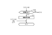
- FIG. 7 illustrates only a process different from the process routine described with reference to FIG.
- step S15 the moving direction of the vehicle in the moving state after stopping is opposite to the moving direction of the vehicle in the moving state before stopping (step S15: YES), and there is a shift range change (step S16). : YES) and when the braking force request value BPRq is less than the stop holding braking force BPTh (step S18: NO), the process proceeds to step S19. If the specified period TRM has not ended yet (step S19: NO), the process proceeds to the next step S201. In step S201, the braking control unit 112 determines whether or not the travel request value has been changed. If the required value for traveling has not been changed (step S201: NO), the process proceeds to step S19 described above.
- step S201 when the required value for travel is changed (step S201: YES), the process proceeds to the next step S21. Then, in step S ⁇ b> 21, the restriction process is performed by the braking control unit 112. Thereafter, this processing routine is terminated.
- step S17 when the shift range is changed in the stop state during the automatic driving of the vehicle and when the vehicle shifts from the stop state to the post-stop movement state, both of the above conditions 3 and 4 are satisfied, step S17.
- the amount of increase in the braking force BP for the vehicle C is smaller than in the case where the braking force increase process is executed. Therefore, it is difficult to suppress the state in which the vehicle is moving. Therefore, it becomes possible to suppress that the vehicle C stops.
- each said embodiment into another embodiment as follows. Even if the braking force request value BPRq is equal to or greater than the stop holding braking force BPTh, the braking force increase process is performed when the moving direction of the vehicle in the post-stop moving state is opposite to the moving direction of the vehicle in the pre-stop moving state. May not be implemented.
- step S201 when the said required value for driving
- the braking force increasing process may not be performed, that is, the braking force may not be increased. Or you may make it implement a restriction
- the braking force increasing process in step S17 increases the braking force on the vehicle by operating the electric parking device instead of the braking actuator 37 that adjusts the WC pressure Pwc. You may do it.
- the electric parking device functions as a braking device.
Landscapes
- Engineering & Computer Science (AREA)
- Transportation (AREA)
- Mechanical Engineering (AREA)
- Automation & Control Theory (AREA)
- Regulating Braking Force (AREA)
Abstract
L'invention concerne un dispositif de commande de freinage (110) qui comprend une unité de détermination (111) qui détermine si une plage de changement de vitesse a changé lorsqu'une transition est effectuée d'un état de déplacement précédant l'arrêt à un état arrêté, et une unité de commande de freinage (112) qui, dans une situation dans laquelle l'unité de détermination (111) a exécuté une détermination positive, exécute un processus d'augmentation de force de freinage lorsqu'une transition est effectuée d'un état arrêté à un état de déplacement suivant l'arrêt. Même lorsqu'une transition est effectuée d'un état arrêté à un état de déplacement suivant l'arrêt dans une situation dans laquelle l'unité de détermination (111) a exécuté une détermination positive, l'unité de commande de freinage (112) exécute un processus d'augmentation ou un processus de limitation de force de freinage à condition que la direction de déplacement du véhicule dans l'état de déplacement suivant l'arrêt soit la direction opposée à la direction de déplacement du véhicule dans l'état de déplacement précédant l'arrêt.
Priority Applications (2)
| Application Number | Priority Date | Filing Date | Title |
|---|---|---|---|
| DE112018001010.4T DE112018001010T5 (de) | 2017-02-24 | 2018-02-23 | Bremssteuergerät für ein Fahrzeug |
| US16/478,658 US20190381979A1 (en) | 2017-02-24 | 2018-02-23 | Braking control device for vehicle |
Applications Claiming Priority (2)
| Application Number | Priority Date | Filing Date | Title |
|---|---|---|---|
| JP2017-033732 | 2017-02-24 | ||
| JP2017033732A JP2018138437A (ja) | 2017-02-24 | 2017-02-24 | 車両の制動制御装置 |
Publications (1)
| Publication Number | Publication Date |
|---|---|
| WO2018155603A1 true WO2018155603A1 (fr) | 2018-08-30 |
Family
ID=63253874
Family Applications (1)
| Application Number | Title | Priority Date | Filing Date |
|---|---|---|---|
| PCT/JP2018/006600 Ceased WO2018155603A1 (fr) | 2017-02-24 | 2018-02-23 | Dispositif de commande de freinage pour véhicule |
Country Status (4)
| Country | Link |
|---|---|
| US (1) | US20190381979A1 (fr) |
| JP (1) | JP2018138437A (fr) |
| DE (1) | DE112018001010T5 (fr) |
| WO (1) | WO2018155603A1 (fr) |
Cited By (1)
| Publication number | Priority date | Publication date | Assignee | Title |
|---|---|---|---|---|
| CN113646218A (zh) * | 2019-03-29 | 2021-11-12 | 株式会社爱德克斯 | 车辆的控制装置 |
Families Citing this family (2)
| Publication number | Priority date | Publication date | Assignee | Title |
|---|---|---|---|---|
| KR102880988B1 (ko) | 2020-10-22 | 2025-11-04 | 현대모비스 주식회사 | 전동식 브레이크 장치 및 제어방법 |
| CN117445906A (zh) * | 2023-11-27 | 2024-01-26 | 博世汽车部件(苏州)有限公司 | 一种自动泊车控制方法及其控制系统 |
Citations (2)
| Publication number | Priority date | Publication date | Assignee | Title |
|---|---|---|---|---|
| JP2000280876A (ja) * | 1999-03-30 | 2000-10-10 | Isuzu Motors Ltd | オートクラッチ車両 |
| JP2016164066A (ja) * | 2010-09-20 | 2016-09-08 | ジャガー ランド ローバー リミテッドJaguar Land Rover Limited | ブレーキ制御に関する改良 |
-
2017
- 2017-02-24 JP JP2017033732A patent/JP2018138437A/ja active Pending
-
2018
- 2018-02-23 US US16/478,658 patent/US20190381979A1/en not_active Abandoned
- 2018-02-23 DE DE112018001010.4T patent/DE112018001010T5/de not_active Ceased
- 2018-02-23 WO PCT/JP2018/006600 patent/WO2018155603A1/fr not_active Ceased
Patent Citations (2)
| Publication number | Priority date | Publication date | Assignee | Title |
|---|---|---|---|---|
| JP2000280876A (ja) * | 1999-03-30 | 2000-10-10 | Isuzu Motors Ltd | オートクラッチ車両 |
| JP2016164066A (ja) * | 2010-09-20 | 2016-09-08 | ジャガー ランド ローバー リミテッドJaguar Land Rover Limited | ブレーキ制御に関する改良 |
Cited By (2)
| Publication number | Priority date | Publication date | Assignee | Title |
|---|---|---|---|---|
| CN113646218A (zh) * | 2019-03-29 | 2021-11-12 | 株式会社爱德克斯 | 车辆的控制装置 |
| CN113646218B (zh) * | 2019-03-29 | 2023-09-22 | 株式会社爱德克斯 | 车辆的控制装置 |
Also Published As
| Publication number | Publication date |
|---|---|
| JP2018138437A (ja) | 2018-09-06 |
| DE112018001010T5 (de) | 2019-11-07 |
| US20190381979A1 (en) | 2019-12-19 |
Similar Documents
| Publication | Publication Date | Title |
|---|---|---|
| JP6353544B2 (ja) | 坂道逆進速度コントロール | |
| EP2017501B1 (fr) | Appareil de contrôle de transmission automatique et la méthode correspondante | |
| JP7207004B2 (ja) | 電動車両の制御装置 | |
| JP2010269671A (ja) | 車両の走行制御装置 | |
| JP2009156092A (ja) | 誤操作判定装置、および車両の駆動制御装置 | |
| US20200198602A1 (en) | Control device for vehicle and vehicle including control device | |
| KR102565356B1 (ko) | 하이브리드 차량의 회생제동 제어 방법 | |
| JP2018019559A (ja) | 駆動力制御方法及び駆動力制御装置 | |
| US20150100222A1 (en) | Automated holding method for a vehicle on a slope | |
| WO2018155603A1 (fr) | Dispositif de commande de freinage pour véhicule | |
| JP6476801B2 (ja) | 制駆動力制御装置及び制駆動力制御方法 | |
| JP5686721B2 (ja) | 電動車両の制御装置 | |
| JP7184456B2 (ja) | 運転補助装置付き車両の走行制御装置 | |
| JP5173330B2 (ja) | 車両走行制御装置 | |
| JP6782608B2 (ja) | パーキングブレーキ制御装置 | |
| JP4329695B2 (ja) | 制動装置の制御装置 | |
| JP2015072044A (ja) | 車両の制御装置 | |
| JP2013123972A (ja) | 車両用制動力制御装置 | |
| JP4797466B2 (ja) | 先行車追従制御装置 | |
| JP2009029424A (ja) | 作業車両の車速制御装置 | |
| CN114829223A (zh) | 驱动力控制方法以及驱动力控制装置 | |
| JP4254428B2 (ja) | 四輪駆動車の駆動力配分制御装置 | |
| JP2020039224A (ja) | 走行制御装置および車両 | |
| JP5163589B2 (ja) | 車両用駆動力制御装置 | |
| JP2020075545A (ja) | 車両用制動装置 |
Legal Events
| Date | Code | Title | Description |
|---|---|---|---|
| 121 | Ep: the epo has been informed by wipo that ep was designated in this application |
Ref document number: 18758387 Country of ref document: EP Kind code of ref document: A1 |
|
| 122 | Ep: pct application non-entry in european phase |
Ref document number: 18758387 Country of ref document: EP Kind code of ref document: A1 |