WO2018159616A1 - 鋳物砂の製造方法および鋳物砂 - Google Patents
鋳物砂の製造方法および鋳物砂 Download PDFInfo
- Publication number
- WO2018159616A1 WO2018159616A1 PCT/JP2018/007281 JP2018007281W WO2018159616A1 WO 2018159616 A1 WO2018159616 A1 WO 2018159616A1 JP 2018007281 W JP2018007281 W JP 2018007281W WO 2018159616 A1 WO2018159616 A1 WO 2018159616A1
- Authority
- WO
- WIPO (PCT)
- Prior art keywords
- sand
- furan resin
- mass
- foundry sand
- artificial
- Prior art date
- Legal status (The legal status is an assumption and is not a legal conclusion. Google has not performed a legal analysis and makes no representation as to the accuracy of the status listed.)
- Ceased
Links
Images


Classifications
-
- B—PERFORMING OPERATIONS; TRANSPORTING
- B22—CASTING; POWDER METALLURGY
- B22C—FOUNDRY MOULDING
- B22C1/00—Compositions of refractory mould or core materials; Grain structures thereof; Chemical or physical features in the formation or manufacture of moulds
- B22C1/16—Compositions of refractory mould or core materials; Grain structures thereof; Chemical or physical features in the formation or manufacture of moulds characterised by the use of binding agents; Mixtures of binding agents
- B22C1/20—Compositions of refractory mould or core materials; Grain structures thereof; Chemical or physical features in the formation or manufacture of moulds characterised by the use of binding agents; Mixtures of binding agents of organic agents
- B22C1/22—Compositions of refractory mould or core materials; Grain structures thereof; Chemical or physical features in the formation or manufacture of moulds characterised by the use of binding agents; Mixtures of binding agents of organic agents of resins or rosins
- B22C1/2233—Compositions of refractory mould or core materials; Grain structures thereof; Chemical or physical features in the formation or manufacture of moulds characterised by the use of binding agents; Mixtures of binding agents of organic agents of resins or rosins obtained otherwise than by reactions only involving carbon-to-carbon unsaturated bonds
- B22C1/224—Furan polymers
-
- B—PERFORMING OPERATIONS; TRANSPORTING
- B22—CASTING; POWDER METALLURGY
- B22C—FOUNDRY MOULDING
- B22C9/00—Moulds or cores; Moulding processes
- B22C9/02—Sand moulds or like moulds for shaped castings
-
- B—PERFORMING OPERATIONS; TRANSPORTING
- B33—ADDITIVE MANUFACTURING TECHNOLOGY
- B33Y—ADDITIVE MANUFACTURING, i.e. MANUFACTURING OF THREE-DIMENSIONAL [3D] OBJECTS BY ADDITIVE DEPOSITION, ADDITIVE AGGLOMERATION OR ADDITIVE LAYERING, e.g. BY 3D PRINTING, STEREOLITHOGRAPHY OR SELECTIVE LASER SINTERING
- B33Y10/00—Processes of additive manufacturing
-
- B—PERFORMING OPERATIONS; TRANSPORTING
- B33—ADDITIVE MANUFACTURING TECHNOLOGY
- B33Y—ADDITIVE MANUFACTURING, i.e. MANUFACTURING OF THREE-DIMENSIONAL [3D] OBJECTS BY ADDITIVE DEPOSITION, ADDITIVE AGGLOMERATION OR ADDITIVE LAYERING, e.g. BY 3D PRINTING, STEREOLITHOGRAPHY OR SELECTIVE LASER SINTERING
- B33Y70/00—Materials specially adapted for additive manufacturing
- B33Y70/10—Composites of different types of material, e.g. mixtures of ceramics and polymers or mixtures of metals and biomaterials
-
- C—CHEMISTRY; METALLURGY
- C04—CEMENTS; CONCRETE; ARTIFICIAL STONE; CERAMICS; REFRACTORIES
- C04B—LIME, MAGNESIA; SLAG; CEMENTS; COMPOSITIONS THEREOF, e.g. MORTARS, CONCRETE OR LIKE BUILDING MATERIALS; ARTIFICIAL STONE; CERAMICS; REFRACTORIES; TREATMENT OF NATURAL STONE
- C04B26/00—Compositions of mortars, concrete or artificial stone, containing only organic binders, e.g. polymer or resin concrete
- C04B26/02—Macromolecular compounds
- C04B26/10—Macromolecular compounds obtained otherwise than by reactions only involving carbon-to-carbon unsaturated bonds
- C04B26/105—Furfuryl alcohol polymers, e.g. furan-polymers
-
- C—CHEMISTRY; METALLURGY
- C08—ORGANIC MACROMOLECULAR COMPOUNDS; THEIR PREPARATION OR CHEMICAL WORKING-UP; COMPOSITIONS BASED THEREON
- C08F—MACROMOLECULAR COMPOUNDS OBTAINED BY REACTIONS ONLY INVOLVING CARBON-TO-CARBON UNSATURATED BONDS
- C08F34/00—Homopolymers and copolymers of cyclic compounds having no unsaturated aliphatic radicals in a side chain and having one or more carbon-to-carbon double bonds in a heterocyclic ring
- C08F34/02—Homopolymers and copolymers of cyclic compounds having no unsaturated aliphatic radicals in a side chain and having one or more carbon-to-carbon double bonds in a heterocyclic ring in a ring containing oxygen
-
- C—CHEMISTRY; METALLURGY
- C08—ORGANIC MACROMOLECULAR COMPOUNDS; THEIR PREPARATION OR CHEMICAL WORKING-UP; COMPOSITIONS BASED THEREON
- C08K—Use of inorganic or non-macromolecular organic substances as compounding ingredients
- C08K3/00—Use of inorganic substances as compounding ingredients
- C08K3/34—Silicon-containing compounds
- C08K3/36—Silica
-
- C—CHEMISTRY; METALLURGY
- C04—CEMENTS; CONCRETE; ARTIFICIAL STONE; CERAMICS; REFRACTORIES
- C04B—LIME, MAGNESIA; SLAG; CEMENTS; COMPOSITIONS THEREOF, e.g. MORTARS, CONCRETE OR LIKE BUILDING MATERIALS; ARTIFICIAL STONE; CERAMICS; REFRACTORIES; TREATMENT OF NATURAL STONE
- C04B2111/00—Mortars, concrete or artificial stone or mixtures to prepare them, characterised by specific function, property or use
- C04B2111/00474—Uses not provided for elsewhere in C04B2111/00
- C04B2111/0087—Uses not provided for elsewhere in C04B2111/00 for metallurgical applications
Definitions
- the present invention relates to a method for producing foundry sand and foundry sand.
- a molten material for example, metal
- a sand mold is known in which a molding agent is added to a foundry sand and then a binder is added to harden the binder to form.
- foundry sand used for a sand mold for example, a foundry sand in which a hardener is kneaded with a mixed sand of natural silica sand and artificial sand has been proposed (for example, see Patent Document 1).
- the present invention provides a method for producing a foundry sand and a foundry sand that can suppress poor molding of the sand mold.
- the present invention [1] includes a step of mixing artificial sand and a furan resin composition containing a furan resin precursor, and a step of mixing a curing agent with the artificial sand mixed with the furan resin composition.
- the hardener includes a method for producing foundry sand containing xylene sulfonic acid.
- the furan resin composition is coated so as to surround each particle of the artificial sand, and then the artificial sand.
- the furan resin composition that coats each of the particles comes into contact with a curing agent and cures to form a furan resin film (layer).
- the activity of the hardener may be reduced due to the components contained in the artificial sand.
- the binder even if the binder is added to the foundry sand to which the curing agent is added, the binder cannot be sufficiently cured, and there is a problem that a molding failure of the sand mold occurs.
- the surface modified layer containing the furan resin covers the artificial sand, the surface modified layer can prevent the hardener from coming into contact with the artificial sand. Therefore, it can suppress that the active ability of a hardening
- the binder when the binder is added, the binder can be reliably cured, and the molding failure of the sand mold can be suppressed.
- a sand mold is modeled by repeating a step of forming the foundry sand in layers and a step of adding a binder to the foundry sand layer and solidifying the added portion of the binder in the foundry sand layer.
- the casting sand is required to have fluidity so that it can be accurately formed into a layer and the casting sand layer can be laminated.
- foundry sand when foundry sand is produced using a curing agent containing para-toluenesulfonic acid, the foundry sand has high fluidity and cannot be stably formed into a layer. Therefore, adding linoleic acid or the like as a fluidizing agent to the foundry sand to adjust the fluidity of the foundry sand is considered, but if a fluidizing agent is added to the foundry sand, it will be fluidized when the foundry sand is recycled. It is necessary to remove the agent, and the recyclability of the foundry sand is reduced.
- foundry sand is produced using a curing agent containing xylene sulfonic acid.
- Such foundry sand has fluidity suitable for three-dimensional additive manufacturing without the addition of a fluidizing agent, can be formed into a layer with high accuracy, and a layer of foundry sand can be laminated.
- the present invention [2] includes the method for producing foundry sand according to the above [1], wherein the temperature is 100 ° C. or lower in the step of mixing the artificial sand and the furan resin composition.
- the furan resin composition can stably coat the artificial sand. Therefore, casting sand having fluidity suitable for three-dimensional additive manufacturing can be stably produced. Further, at a temperature exceeding 100 ° C., the production cost can be reduced as compared with the case where artificial sand and the furan resin composition are mixed.
- the mixing ratio of xylene sulfonic acid is 0.3 mass part or more and 3 mass parts or less with respect to 1 mass part of furan resin precursor, As described in said [1] or [2].
- the present invention [4] has artificial sand, a surface modified layer containing a furan resin that covers the artificial sand, and a curing agent layer that adheres to the surface modified layer, wherein the curing agent layer is It contains foundry sand, containing xylene sulfonic acid.
- Such a configuration can be suitably used for three-dimensional additive manufacturing while suppressing poor molding of the sand mold.
- foundry sand that can suppress poor molding of the sand mold can be produced. According to the foundry sand of the present invention, the molding failure of the sand mold can be suppressed.
- FIG. 1 is a schematic configuration diagram of foundry sand manufactured according to an embodiment of the present invention.
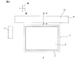
- FIG. 2 is a plan view of an embodiment of a 3D printer to which the foundry sand shown in FIG. 1 can be applied.
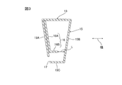
- 3 is a cross-sectional view taken along the line AA of the recoater shown in FIG.
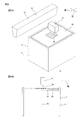
- FIG. 4A is a perspective view of the 3D printer shown in FIG. 2 and shows a process in which the recoater forms a first foundry sand layer.
- FIG. 4B is an explanatory diagram for explaining the process illustrated in FIG. 4A.
- FIG. 5A is a perspective view of the 3D printer shown in FIG. 2 and shows a process in which the jet head adds a binder to the first foundry sand layer.
- FIG. 5B is an explanatory diagram for explaining the process illustrated in FIG. 5A.
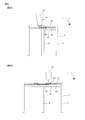
- FIG. 6A shows a step of forming a second foundry sand layer on the first foundry sand layer following FIG. 5B.
- FIG. 6B shows a step of adding a binder to the second foundry sand layer subsequent to FIG. 6A.
- FIG. 7A shows a step of forming a sand mold by sequentially repeating the formation of a layer of foundry sand and the addition of a binder, following FIG. 6B.
- FIG. 7B is a perspective view of the sand mold shown in FIG. 7A.
- FIG. 8A is a perspective view of a test column used for a bending strength test in each example and each comparative example.
- FIG. 8B shows a state in which the test column shown in FIG. 8A is sandwiched between test devices.
- the method for producing foundry sand of the present invention includes a step of mixing artificial sand and a furan resin composition (resin mixing step), and a step of mixing a hardener with the artificial sand mixed with the furan resin composition (hardener mixing). Process).
- Resin mixing step In the resin mixing step, artificial sand and a furan resin composition are mixed. Therefore, first, artificial sand and a furan resin composition are prepared.
- (1-1) Artificial sand Artificial sand is an aggregate of a plurality of particles, and is produced by a known method (for example, a sintering method, a melting method, a flame melting method, etc.).
- artificial sand examples include aluminum oxide sand (alumina sand), mullite sand, and mullite-zircon sand. Artificial sand can be used alone or in combination of two or more. Among the artificial sand, mullite sand is preferable.
- Mullite sand is mainly composed of a mixed composition compound (aluminosilicate) of aluminum oxide (alumina) and silicon dioxide (silica).
- aluminosilicate aluminum oxide
- silicon dioxide silicon dioxide
- the content ratio of aluminum oxide is, for example, 50% by mass or more, preferably 60% by mass or more, more preferably 65% by mass or more, for example, 90% by mass or less, preferably 80% by mass with respect to the total amount of mullite sand. % Or less.
- the content ratio of silicon dioxide is, for example, 5% by mass or more, preferably 15% by mass or more, for example, 45% by mass or less, preferably 40% by mass or less, more preferably 30% by mass with respect to the total amount of mullite sand. % Or less.
- Such mullite sand can be prepared, for example, by the method described in JP-A-61-63333 or the method described in JP-A-2003-251434.
- mullite sand can be used, and examples of commercially available mullite sand include Spearl (manufactured by Yamakawa Sangyo Co., Ltd.), Cera Beads (manufactured by ITOCHU CERATECH), and the like.
- Artificial sand contains particles having a nominal size of 53 ⁇ m (281 mesh) or more and 150 ⁇ m (100 mesh) or less (hereinafter referred to as 53-150 ⁇ m particles), and if necessary, the nominal size is 53 ⁇ m (281). Particles (hereinafter referred to as PAN) or particles having a nominal size exceeding 150 ⁇ m (100 mesh) (hereinafter referred to as particles exceeding 150 ⁇ m).
- the content ratio of 53-150 ⁇ m particles is, for example, 20% by mass or more, preferably 99.0% by mass or more, for example, 100% by mass or less, with respect to the total amount of artificial sand.
- the content ratio of the 53-150 ⁇ m particles is within the above range, the sand mold surface roughness can be reduced and casting sand having fluidity suitable for three-dimensional additive manufacturing can be reliably produced. .
- the content ratio of PAN is, for example, more than 0% by mass, for example, 10% by mass or less, preferably 0.5% by mass or less with respect to the total amount of sand.
- the content ratio of particles exceeding 150 ⁇ m is, for example, more than 0% by mass, for example, 10% by mass or less, preferably 0.5% by mass with respect to the total amount of sand. It is as follows.
- artificial sand may contain feldspar.
- the feldspar is an aluminosilicate containing alkali metal and / or alkaline earth metal.
- feldspar for example, potassium feldspar (K 2 O ⁇ Al 2 O 3 ⁇ 6SiO 2), soda feldspar (Na 2 O ⁇ Al 2 O 3 ⁇ 6SiO 2) , and the like.
- the content ratio of feldspar exceeds 0% by mass, for example, 10% by mass or less, preferably 5% by mass or less, with respect to the total amount of artificial sand.
- natural silica sand can be added to the artificial sand.
- the addition ratio of natural silica sand is, for example, more than 0 parts by mass and 80 parts by mass or less with respect to 100 parts by mass of artificial sand.
- furan resin composition is a curable resin composition that becomes a furan resin when cured, and is in a completely cured state in the presence of an acid, for example, at 35 ° C. or higher and lower than 150 ° C. C stage).
- the furan resin composition contains a furan resin precursor.
- furan resin precursor examples include furfuryl alcohol and furan resin prepolymer.
- furan resin prepolymer for example, a furfuryl alcohol homopolymer, a copolymer of furfuryl alcohol and an aldehyde compound, a copolymer of furfuryl alcohol, urea and an aldehyde compound (urea-modified furan resin prepolymer), Examples thereof include a copolymer of furfuryl alcohol and furfural.
- Furan resin prepolymers can be used alone or in combination of two or more.
- a copolymer of furfuryl alcohol, urea and an aldehyde compound (urea-modified furan resin prepolymer) is preferable.
- the aldehyde compound as the monomer of the urea-modified furan resin prepolymer include formaldehyde, acetaldehyde, glyoxal, paraformaldehyde, and preferably paraformaldehyde.
- Such furan resin precursor may be either furfuryl alcohol or furan resin prepolymer, but preferably furfuryl alcohol and furan resin prepolymer are used in combination.
- the content ratio of the furan resin precursor is, for example, 10% by mass or more, preferably 50% by mass or more, more preferably 60% by mass or more, and particularly preferably 90% by mass with respect to the total amount of the furan resin composition. For example, it is 95% by mass or less.
- the content ratio of the furan resin prepolymer is, for example, 1 part by mass or more, preferably 100 parts per 100 parts by mass of furfuryl alcohol. It is 150 parts by mass or more, for example, 300 parts by mass or less, preferably 150 parts by mass or more.
- the furan resin composition can contain a solvent, a crosslinking agent, and, if necessary, a curing accelerator.
- Examples of the solvent include water, acetone, ethyl acetate, alcohol and the like, and preferably water.
- the content ratio of the solvent is, for example, 0.01% by mass or more, preferably 1% by mass or more, for example, 50% by mass or less, preferably 10% by mass or less, with respect to the total amount of the furan resin composition.
- crosslinking agent examples include silane.
- the content of the crosslinking agent is, for example, 0.01% by mass or more, preferably 0.5% by mass or more, for example, 20% by mass or less, preferably 3% by mass or less, with respect to the total amount of the furan resin composition. is there.
- curing accelerator examples include resorcin, cresol, hydroquinone, phloroglucinol, methylene bisphenol, bishydroxymethyl furan, and the like.
- the stirring device includes, for example, a stirring tank, a stirring blade disposed in the stirring tank and rotatable, and a heater capable of heating the inside of the stirring tank.
- the mixing ratio of the furan resin composition is, for example, 0.005 parts by mass or more, preferably 0.10 parts by mass or more, more preferably 0.15 parts by mass or more, particularly preferably 100 parts by mass of artificial sand. Is 0.20 parts by mass or more, for example, 3 parts by mass or less, preferably 0.50 parts by mass or less, and more preferably 0.30 parts by mass or less.
- the mixing ratio of the furan resin composition is not less than the above lower limit, the artificial sand can be reliably coated with the furan resin.
- the mixing ratio of the furan resin composition is not more than the above upper limit, it is possible to reduce the amount of water generated in the polymerization reaction (described later) of the furan resin precursor, so that the viscosity of the foundry sand excessively increases. It can be suppressed and the strength of the sand mold can be improved.
- the mixing temperature is, for example, 0 ° C. or higher, preferably 35 ° C. or higher, preferably 70 ° C. or higher, such as 150 ° C. or lower, preferably 100 ° C. or lower, more preferably 90 ° C. or lower, and particularly preferably 80 ° C. or lower. It is below °C.
- the mixing temperature is equal to or higher than the above lower limit, water generated in the polymerization reaction (described later) of the furan resin precursor can be stably removed. Therefore, since the water content in the foundry sand can be reduced, the viscosity of the foundry sand can be prevented from excessively increasing.
- the mixing temperature is 70 ° C. or higher, water can be surely removed, and in the resin mixing step, a part of the furan resin composition is coated so as to surround the artificial sand, and then thermally cured. Therefore, since it can suppress further that a hardening
- the mixing temperature is not more than the above upper limit, it is possible to suppress an excessive increase in the curing rate of the furan resin composition, and the furan resin composition can stably coat artificial sand. If the mixing temperature exceeds the above upper limit, the furan resin composition may be cured without sufficiently covering the artificial sand. In this case, the shape of the foundry sand becomes distorted, and the fluidity of the foundry sand may be excessively lowered.
- the mixing temperature is equal to or lower than the above upper limit, the furan resin composition can stably cover the artificial sand, so that it is possible to suppress the fluidity of the foundry sand from being excessively lowered. Further, since the mixing temperature is not more than the above upper limit, the manufacturing cost can be reduced.
- the stirring time in the resin mixing step is, for example, 1 second or longer, preferably 3 seconds or longer, for example 20 seconds or shorter, preferably 20 seconds or shorter, when the stirring target (mixture of artificial sand and resin composition) is 1 kg. 10 seconds or less.
- the stirring time is N times the above when the stirring target is N kg.
- the furan resin composition is coated so as to surround each particle of the artificial sand.
- the curing agent is mixed with the artificial sand mixed with the furan resin composition.
- the curing agent is an acid catalyst that cures the furan resin precursor (to a fully cured state).
- the curing agent contains xylene sulfonic acid as an acid component, and preferably contains only xylene sulfonic acid as an acid component.
- xylenesulfonic acid As xylenesulfonic acid, ortho-xylenesulfonic acid (2,3-dimethylbenzenesulfonic acid, 3,4-dimethylbenzenesulfonic acid), metaxylenesulfonic acid (2,4-dimethylbenzenesulfonic acid, 3,5-dimethylbenzenesulfonic acid) Acid, 2,6-dimethylbenzenesulfonic acid) and paraxylenesulfonic acid (2,5-dimethylbenzenesulfonic acid).
- xylene sulfonic acids can be used alone or in combination of two or more.
- the content ratio of xylene sulfonic acid is, for example, 90.0% by mass or more, preferably 95.0% by mass or more, for example, 100% by mass or less, preferably 97.0% by mass or less, based on the total amount of the curing agent. It is.
- the curing agent may contain a residue in the manufacturing process of the curing agent.
- Such a process may be carried out with the same stirrer as in the above resin mixing step, or the artificial sand mixed with the furan resin composition is transferred and carried out with a stirrer different from the above resin mixing step. May be.
- the mixing ratio of the curing agent is, for example, 0.005 parts by mass or more, preferably 0.05 parts by mass or more, more preferably 0.15 parts by mass or more, particularly preferably 100 parts by mass of artificial sand. 0.20 parts by mass or more, for example, 3 parts by mass or less, preferably 0.50 parts by mass or less, and more preferably 0.30 parts by mass or less.
- the furan resin composition covering the artificial sand can be reliably cured. It can suppress that the viscosity of foundry sand rises too much that the mixture ratio of a hardening
- the mixing ratio of xylene sulfonic acid in the curing agent is, for example, 0.1 part by mass or more, preferably 0.3 part by mass or more, with respect to 1 part by mass of the furan resin precursor in the furan resin composition. More preferably, it is 0.8 parts by mass or more, for example, 3 parts by mass or less, preferably 2 parts by mass or less, and more preferably 1.2 parts by mass or less.
- the mixing ratio of xylene sulfonic acid is in the above range, the strength of the sand mold formed by the foundry sand can be improved.
- the mixing temperature range in the curing agent mixing step is the same as the mixing temperature range in the resin mixing step, and the stirring time range in the curing agent mixing step is the same as the stirring time range in the resin mixing step. is there.
- the furan resin composition covering the artificial sand is cured by contact with xylenesulfonic acid to form a furan resin film (layer) that is a cured product.
- xylene sulfonic acid acts as a catalyst.
- the furan resin composition contains furfuryl alcohol, as shown in the following formula (1), the furfuryl alcohol is subjected to condensation polymerization by contacting with xylene sulfonic acid (in the formula, HA). And furan resin is formed.
- xylene sulfonic acid in the formula, HA
- water is generated in the condensation polymerization of furfuryl alcohol.
- a part of the water generated by the reaction is leached on the surface of the surface modification layer and then removed by evaporation.
- the curing agent xylene sulfonic acid
- the curing agent is extruded onto the surface of the surface modification layer together with water.
- curing agent adheres to the surface of a surface modification layer, and forms a hardening
- the water which did not ooze out on the surface of the surface modification layer is contained in, for example, furan resin, or when artificial sand contains potassium feldspar or soda feldspar, the following formula (2) and formula As shown in (3), it is removed by reacting with potassium feldspar and soda feldspar.
- Foundry sand is produced as described above.
- the foundry sand is a set of a plurality of particles. In FIG. 1, for convenience, one particle of the foundry sand is shown as the foundry sand 1.
- the foundry sand 1 includes artificial sand 2, a surface modified layer 3 containing a furan resin covering the artificial sand 2, and a hardener layer 4 attached to the surface modified layer, and preferably consists of them.
- Artificial sand 2 indicates each particle of the artificial sand described above.
- the furan resin contained in the surface modification layer 3 is a completely cured product of the furan resin composition, and the curing reaction has been completed. For example, even when heated, the curing reaction does not proceed any further.
- the thickness of the surface modification layer 3 is, for example, 0.01 ⁇ m or more, preferably 0.1 ⁇ m or more, for example, 10 ⁇ m or less, preferably 1 ⁇ m or less.
- the surface modified layer 3 may contain a component other than the furan resin, for example, an uncured furan resin precursor, but the content ratio of the furan resin is, for example, 80% by mass or more, preferably 90% by mass or more, for example, 100% by mass or less.
- the curing agent layer 4 is disposed on the surface of the surface modification layer 3.
- the curing agent layer 4 contains xylene sulfonic acid, and preferably consists of xylene sulfonic acid.
- Sand mold modeling method (4-1) 3D Printer
- a foundry sand 1 can be used for modeling various sand molds, it is particularly useful as a foundry sand for three-dimensional layered modeling, that is, for a 3D printer.
- the foundry sand 1 is shaped into a sand mold 30 (see FIG. 7B) by a 3D printer (three-dimensional layered shaping apparatus) 6 as shown in FIGS. 2 to 7B.
- the 3D printer 6 is a device that can form a sand mold from 3D-CAD data, and includes a modeling unit 7, a recoater 13, a jet head 14, and an operation unit (not shown).
- the modeling unit 7 includes a job box 11, a stage 12, and a support shaft 18.
- the job box 11 has a substantially rectangular shape in plan view and extends in the vertical direction. The upper end of the job box 11 is open.
- the stage 12 has a substantially rectangular plate shape in plan view, and is arranged in the job box 11.
- the stage 12 is fixed to the upper end of a support shaft 18 that can be moved up and down.
- the stage 12 can move up and down in the job box 11 by raising and lowering the support shaft 18.
- the recoater 13 can store the foundry sand and is configured to supply the stored foundry sand to the stage 12.
- the recoater 13 is movable in the surface direction of the stage 12 so as to pass above the stage 12 with an interval in a state parallel to the stage 12.
- the direction in which the recoater 13 can move is defined as the horizontal direction (X direction), and the direction perpendicular to both the horizontal direction and the vertical direction is defined as the vertical direction (Y direction).
- the recoater 13 includes a container 15 and a blade 16.
- the container 15 can store the above foundry sand.
- the container 15 extends in the vertical direction (see FIG. 2).
- the container 15 includes a first wall 15A and a second wall 15B that are spaced apart from each other in the lateral direction, a bottom wall 15C located at the lower end of the container 15, and an opening 17 that communicates the inside and outside of the container 15. Have.
- the opening 17 is formed at the lower end portion of the first wall 15A, and is partitioned between the first wall 15A and the bottom wall 15C.
- the opening 17 extends in the vertical direction.
- the vertical dimension of the opening 17 is substantially the same as the vertical dimension of the stage 12.
- the blade 16 is disposed in the container 15.
- the blade 16 can vibrate so that the foundry sand stored in the container 15 is discharged from the opening 17.
- the blade 16 has an L shape when viewed from the side, and includes a plate 16A and a protrusion 16B.
- the plate 16A is disposed with a space from the first wall 15A along the first wall 15A.
- the protruding portion 16B protrudes from the lower end portion of the plate 16A toward the second wall 15B.
- the free end portion (the end portion on the opposite side of the plate 16A) of the protruding portion 16B is disposed with a space in the lateral direction with respect to the second wall 15B.
- the distance L between the free end portion of the protruding portion 16B and the second wall 15B in the lateral direction is, for example, 0.3 mm or more, preferably 0.7 mm or more, for example, 6.0 mm or less, preferably 1. 5 mm or less.
- the recoater 13 is connected to a foundry sand tank in which the foundry sand is accommodated, and when the stored amount of foundry sand in the container 15 becomes a predetermined value or less, the foundry sand tank is replenished.
- the jet head 14 is configured to supply a binder described later to a layer of foundry sand formed on the stage 12.
- the jet head 14 is connected to a binder tank that accommodates the binder, and the binder is supplied from the binder tank.
- the jet head 14 is electrically connected to an operation unit (not shown).
- the jet head 14 is movable in the vertical direction and the horizontal direction so as to pass above the stage 12 with an interval in a state parallel to the stage 12.
- the binder supplied by the jet head 14 examples include the furan resin composition described above. That is, the binder contains a furan resin precursor.
- the furan resin precursor contained in the binder preferably includes furfuryl alcohol, and more preferably includes single use of furfuryl alcohol.
- the content ratio of the furan resin precursor is, for example, 1% by mass or more, preferably 10% by mass or more, more preferably 85% by mass or more, for example, 100% by mass or less, preferably 100% by mass or less, based on the total amount of the binder. It is 95 mass% or less.
- the binder can contain the above-described curing accelerator and the like in addition to the above furan resin precursor.
- the curing accelerator preferably, resorcin is used.
- the content rate of a hardening accelerator is 1 mass% or more with respect to the whole quantity of a binder, Preferably, it is 5 mass% or more, for example, 30 mass% or less, Preferably, it is 15 mass% or less.
- (4-2) Sand Mold Modeling by 3D Printer In the 3D printer 6, as shown in FIGS. 4A and 4B, first, the recoater 13 for storing foundry sand moves laterally and the blade 16 slightly vibrates. Thus, the foundry sand is discharged from the opening 17 in a layered manner onto the stage 12 (see FIG. 3).
- a first foundry sand layer 25 (cast sand layer) is formed on the stage 12. That is, the foundry sand is formed in layers on the stage 12 without adding a fluidizing agent.
- the thickness of the first foundry sand layer 25 is larger than the particle size of the maximum particles contained in the foundry sand, and is, for example, 200 ⁇ m or more, preferably 250 ⁇ m or more, for example, 400 ⁇ m or less, preferably 300 ⁇ m or less.
- the jet head 14 adds a binder to the sand mold portion of the first foundry sand layer 25 based on 3D-CAD data input from an operation unit (not shown).
- the first addition portion 26 is formed.
- the added binder comes into contact with the curing agent (xylene sulfonic acid) adhering to the surface modification layer of the foundry sand and hardens to adhere the foundry sand to each other.
- the 1st addition part 26 is hardened with binder hardened
- the recoater 13 again discharges the foundry sand on the first foundry sand layer 25 so as to be layered.
- the second foundry sand layer 27 (cast sand layer) is formed.
- the jet head 14 adds a binder to the sand mold portion of the second cast sand layer 27 to form the second addition portion 28.
- the formation of the casting sand layer by the recoater 13 and the addition of the binder by the jet head 14 are sequentially repeated.
- the formation of the foundry sand layer is repeated n times, the first foundry sand layer 25 to the nth foundry sand layer are sequentially laminated, and the first added portion 26 to the nth added portion are sequentially formed.
- the thickness range of each foundry sand layer is the same as the thickness range of the first foundry sand layer 25.
- the sand mold 30 is manufactured.
- the sand mold 30 contains foundry sand and a hardened binder that adheres the foundry sand to each other. 6B and 7A, for convenience, the surface of the sand mold 30 is shown as having a step, but actually, the surface of the sand mold 30 is formed substantially smooth as shown in FIG. 7B. Yes.
- the foundry sand 1 including the artificial sand 2 and the surface modified layer 3 containing the furan resin covering the artificial sand 2 can be manufactured.
- the surface modified layer 3 containing the furan resin covers the artificial sand 2
- the surface modified layer 3 can prevent the hardener from coming into contact with the artificial sand 2.
- the activity of the curing agent may be reduced due to the components contained in the artificial sand.
- potassium feldspar reacts with water as shown in the above formula (2) to produce potassium carbonate.
- xylene sulfonic acid (HA) in the curing agent is converted into weak acid (KA), and the activity of the curing agent is reduced.
- the foundry sand 1 since the contact between the hardener and the artificial sand 2 is suppressed by the surface modification layer 3, it is possible to suppress the decrease in the activity of the hardener. Therefore, when a binder is added to the foundry sand 1, the binder can be reliably cured, and a molding failure of the sand mold 30 can be suppressed.
- the foundry sand described above has fluidity suitable for three-dimensional additive manufacturing. Therefore, as shown in FIGS. 2 to 7B, without adding a fluidizing agent to the foundry sand, the foundry sand can be accurately formed into a layer in the three-dimensional laminating method (3D printer), and the foundry sand layer Can be laminated.
- the foundry sand to which no binder is added is removed. Since the foundry sand to which no binder is added does not contain a fluidizing agent, it can be reused as it is (without any treatment) by collecting it. Therefore, the recyclability of foundry sand can be improved.
- the fluidizing agent is added to the foundry sand, if the foundry sand to which the fluidizing agent is added is reused as it is, the fluidizing agent is deteriorated, and in the three-dimensional laminating method (3D printer), the foundry sand is removed. In some cases, it cannot be formed into a layer with high accuracy.
- the furan resin composition can stably coat artificial sand.
- the fluidity of the foundry sand can be prevented from excessively decreasing, and the foundry sand having fluidity suitable for three-dimensional additive manufacturing can be stably produced.
- the production cost can be reduced as compared with the case where artificial sand and the furan resin composition are mixed.
- the mixing ratio of xylene sulfonic acid is preferably 0.3 parts by mass or more and 3 parts by mass or less with respect to 1 part by mass of the furan resin precursor. Therefore, casting sand having fluidity suitable for three-dimensional additive manufacturing can be manufactured more stably, and the strength of a sand mold formed by the casting sand can be improved.
- the furan resin composition is added after preheating artificial sand in the resin mixing step, but the present invention is not limited to this. After mixing the artificial sand and the furan resin composition, the mixing temperature can be adjusted to the above range. Also by this, the same effect as the above-described embodiment can be obtained.
- Artificial sand A (mullite sand, trade name: ESPARL # 100DAM, manufactured by Yamakawa Sangyo Co., Ltd.) and a furan resin composition (resin composition) shown in Table 1 were prepared. Artificial sand A contained potassium feldspar and soda feldspar. The AFS (particle size index) of the artificial sand A was 106.4.
- the furan resin composition is added according to the formulation shown in Table 2, and stirred until artificial sand A and the furan resin composition are uniform. Mixed (resin mixing step).
- the hardener A containing xylene sulfonic acid (XS) is added to the artificial sand A mixed with the furan resin composition in the formulation shown in Table 2, so that the artificial sand A to which the hardener A is added is smooth.
- the mixture was stirred and mixed until it flowed (curing agent mixing step).
- Curing agent A contained xylene sulfonic acid.
- concentration of xylene sulfonic acid was 95.0% by mass or more and 97.0% by mass or less with respect to the total amount of the curing agent.
- the mixing temperature shown in Table 2 was maintained in the temperature range of 5 to 10 ° C.
- Example 7 Foundry sand was obtained in the same manner as in Example 2 except that the artificial sand A was changed to artificial sand B (mullite sand, trade name: Cerabead # 1450, manufactured by ITOCHU CERATECH).
- the artificial sand B contained potash feldspar and soda feldspar.
- the AFS particle size index of the artificial sand B was 108.8.
- Example 1 Foundry sand was obtained in the same manner as in Example 2 except that the curing agent A was changed to the curing agent B containing paratoluenesulfonic acid (PTS).
- Curing agent B contained p-toluenesulfonic acid, sulfuric acid, and water.
- the concentration of paratoluenesulfonic acid was 63% by mass with respect to the total amount of the curing agent B, and the concentration of sulfuric acid was 1.0% by mass with respect to the total amount of the curing agent B.
- the foundry sand layer could be formed with high accuracy and the foundry sand layer could be accurately laminated.
- test column was allowed to stand for each time shown in Table 2 under conditions of a room temperature of 24 ° C. and a humidity of 45%.
- test column was set in a test apparatus (Universal Strength Machine PFG, manufactured by Simpson) so as to be sandwiched from the outside in the length direction of the test column.
- a test apparatus Universal Strength Machine PFG, manufactured by Simpson
- the method for producing foundry sand according to the present invention can be suitably used for producing sand for molding, which is used for producing various industrial products, and particularly for foundry sand for three-dimensional additive manufacturing.
- the foundry sand of the present invention can be suitably used for sand molds used for manufacturing various industrial products, particularly sand molds manufactured by three-dimensional additive manufacturing.
Landscapes
- Chemical & Material Sciences (AREA)
- Engineering & Computer Science (AREA)
- Materials Engineering (AREA)
- Chemical Kinetics & Catalysis (AREA)
- Ceramic Engineering (AREA)
- Organic Chemistry (AREA)
- Mechanical Engineering (AREA)
- Structural Engineering (AREA)
- Manufacturing & Machinery (AREA)
- Medicinal Chemistry (AREA)
- Health & Medical Sciences (AREA)
- Polymers & Plastics (AREA)
- Composite Materials (AREA)
- Civil Engineering (AREA)
- Mold Materials And Core Materials (AREA)
- Laminated Bodies (AREA)
Abstract
鋳物砂の製造方法は、人工砂と、フラン樹脂前駆体を含むフラン樹脂組成物とを混合する工程と、フラン樹脂組成物が混合された人工砂に硬化剤を混合する工程と、を含み、硬化剤が、キシレンスルホン酸を含む。
Description
本発明は、鋳物砂の製造方法および鋳物砂に関する。
鋳造により製品(鋳物)を作製するには、まず、鋳型を造形した後、その鋳型に溶解した材料(例えば、金属など)を流し込み、所要の形状に形成する。
そのような鋳型として、鋳物砂に硬化剤を添加した後にバインダを添加して、バインダを硬化させて造形する砂型が知られている。
そして、砂型に用いられる鋳物砂として、例えば、天然珪砂および人工砂の混合砂に、硬化剤が混練された鋳物砂が提案されている(例えば、特許文献1参照。)。
しかし、特許文献1に記載の鋳物砂にバインダを添加しても、バインダを十分に硬化させることができず、砂型の造形不良が生じる場合がある。
そこで、本発明は、砂型の造形不良を抑制できる鋳物砂の製造方法および鋳物砂を提供する。
本発明[1]は、人工砂と、フラン樹脂前駆体を含むフラン樹脂組成物とを混合する工程と、前記フラン樹脂組成物が混合された人工砂に硬化剤を混合する工程と、を含み、前記硬化剤が、キシレンスルホン酸を含む、鋳物砂の製造方法を含んでいる。
このような方法によれば、人工砂とフラン樹脂組成物とを混合した後に、硬化剤を混合するので、フラン樹脂組成物が人工砂の各粒子の周囲を取り囲むように被覆した後、人工砂の各粒子を被覆するフラン樹脂組成物が、硬化剤と接触し硬化してフラン樹脂膜(層)となる。これによって、人工砂と、人工砂を被覆するフラン樹脂を含有する表面改質層とを備える鋳物砂が製造できる。
しかるに、特許文献1に記載の鋳物砂のように人工砂と硬化剤とが直接接触すると、人工砂に含有される成分により、硬化剤の活性能が低下してしまう場合がある。この場合、硬化剤が添加された鋳物砂にバインダを添加しても、バインダを十分に硬化させることができず、砂型の造形不良が生じるという不具合がある。
一方、上記の鋳物砂では、フラン樹脂を含有する表面改質層が人工砂を被覆しているので、表面改質層により硬化剤が人工砂と接触することを抑制できる。そのため、硬化剤の活性能が、人工砂に含有される成分により、低下することを抑制できる。
その結果、上記の鋳物砂では、バインダを添加したときに、バインダを確実に硬化させることができ、砂型の造形不良を抑制することができる。
また、砂型を3次元積層法(すなわち、3Dプリンタ)により造形することが検討されている。3次元積層造形では、鋳物砂を層状に形成する工程と、鋳物砂の層にバインダを添加して、鋳物砂の層におけるバインダの添加部分を固める工程とを繰り返して、砂型を造形する。
そのため、鋳物砂には、精度よく層状に形成でき、かつ、鋳物砂の層を積層できるような流動性が要求される。
しかし、パラトルエンスルホン酸を含む硬化剤を用いて鋳物砂が製造された場合、鋳物砂の流動性が高く、鋳物砂を安定して層状に形成できない。そこで、リノール酸などを流動化剤として鋳物砂に添加し、鋳物砂の流動性を調整することが検討されるが、鋳物砂に流動化剤を添加すると、鋳物砂をリサイクルするときに流動化剤を除去する必要があり、鋳物砂のリサイクル性が低下してしまう。
一方、上記の鋳物砂の製造方法では、キシレンスルホン酸を含む硬化剤を用いて鋳物砂が製造されている。そのような鋳物砂は、流動化剤の添加なしに、3次元積層造形に好適な流動性を有しており、精度よく層状に形成でき、かつ、鋳物砂の層を積層することができる。
よって、本発明によれば、砂型の造形不良を抑制することができながら、3次元積層造形に好適に利用できる鋳物砂を製造することができる。
本発明[2]は、前記人工砂とフラン樹脂組成物とを混合する工程において、温度が100℃以下である、上記[1]に記載の鋳物砂の製造方法を含んでいる。
このような方法によれば、100℃以下において人工砂とフラン樹脂組成物とを混合するので、フラン樹脂組成物が安定して人工砂を被覆することができる。そのため、3次元積層造形に好適な流動性を有する鋳物砂を安定して製造することができる。また、100℃を超過する温度において、人工砂とフラン樹脂組成物とを混合する場合と比較して製造コストの低減を図ることができる。
本発明[3]は、キシレンスルホン酸の混合割合は、フラン樹脂前駆体1質量部に対して、0.3質量部以上3質量部以下である、上記[1]または[2]に記載の鋳物砂の製造方法を含んでいる。
このような方法によれば、キシレンスルホン酸の混合割合が上記の範囲であるので、3次元積層造形に好適な流動性を有する鋳物砂をより安定して製造することができ、かつ、鋳物砂から造形される砂型の強度の向上を図ることができる。
本発明[4]は、人工砂と、前記人工砂を被覆するフラン樹脂を含有する表面改質層と、前記表面改質層に付着する硬化剤層と、を有し、前記硬化剤層が、キシレンスルホン酸を含む、鋳物砂を含んでいる。
このような構成によれば、砂型の造形不良を抑制することができながら、3次元積層造形に好適に利用できる。
本発明の鋳物砂の製造方法によれば、砂型の造形不良を抑制できる鋳物砂を製造できる。本発明の鋳物砂によれば、砂型の造形不良を抑制することができる。
<鋳物砂の製造方法>
本発明の鋳物砂の製造方法は、人工砂とフラン樹脂組成物とを混合する工程(樹脂混合工程)と、フラン樹脂組成物が混合された人工砂に硬化剤を混合する工程(硬化剤混合工程)とを含んでいる。
本発明の鋳物砂の製造方法は、人工砂とフラン樹脂組成物とを混合する工程(樹脂混合工程)と、フラン樹脂組成物が混合された人工砂に硬化剤を混合する工程(硬化剤混合工程)とを含んでいる。
1.樹脂混合工程
樹脂混合工程では、人工砂とフラン樹脂組成物とを混合する。そのため、まず、人工砂と、フラン樹脂組成物とを準備する。
樹脂混合工程では、人工砂とフラン樹脂組成物とを混合する。そのため、まず、人工砂と、フラン樹脂組成物とを準備する。
(1-1)人工砂
人工砂は、複数の粒子の集合であり、公知の方法(例えば、焼結法、溶融法、火炎溶融法など)により製造される。
人工砂は、複数の粒子の集合であり、公知の方法(例えば、焼結法、溶融法、火炎溶融法など)により製造される。
人工砂として、例えば、酸化アルミニウム砂(アルミナ砂)、ムライト砂、ムライト-ジルコン砂などが挙げられる。人工砂は、単独使用または2種類以上併用することができる。人工砂のなかでは、好ましくは、ムライト砂が挙げられる。
ムライト砂は、酸化アルミニウム(アルミナ)と二酸化珪素(シリカ)との混合組成化合物(アルミノケイ酸塩)を主成分としている。
酸化アルミニウムの含有割合は、ムライト砂全量に対して、例えば、50質量%以上、好ましくは、60質量%以上、さらに好ましくは、65質量%以上、例えば、90質量%以下、好ましくは、80質量%以下である。
二酸化珪素の含有割合は、ムライト砂全量に対して、例えば、5質量%以上、好ましくは、15質量%以上、例えば、45質量%以下、好ましくは、40質量%以下、さらに好ましくは、30質量%以下である。
このようなムライト砂は、例えば、特開昭61-63333号公報に記載の方法や、特開2003-251434号公報に記載の方法により調製することができる。
また、ムライト砂は、市販品を用いることもでき、ムライト砂の市販品として、例えば、エスパール(山川産業社製)、セラビーズ(伊藤忠セラテック社製)などが挙げられる。
また、人工砂は、呼び寸法が53μm(281メッシュ)以上150μm(100メッシュ)以下の粒子(以下、53-150μm粒子とする。)を含んでおり、必要に応じて、呼び寸法が53μm(281メッシュ)未満の粒子(以下、PANとする。)や、呼び寸法が150μm(100メッシュ)を超過する粒子(以下、150μm超過粒子とする。)を含むことができる。
53-150μm粒子の含有割合は、人工砂全量に対して、例えば、20質量%以上、好ましくは、99.0質量%以上、例えば、100質量%以下である。
53-150μm粒子の含有割合が上記範囲内であれば、砂型の表面粗さの低減を図ることができるとともに、3次元積層造形に好適な流動性を有する鋳物砂を確実に製造することができる。
また、人工砂がPANを含む場合、PANの含有割合は、砂全量に対して、例えば、0質量%を超過し、例えば、10質量%以下、好ましくは、0.5質量%以下である。
また、人工砂が150μm超過粒子を含む場合、150μm超過粒子の含有割合は、砂全量に対して、例えば、0質量%を超過し、例えば、10質量%以下、好ましくは、0.5質量%以下である。
また、人工砂は、長石を含んでいてもよい。長石は、アルカリ金属および/またはアルカリ土類金属を含有するアルミノケイ酸塩である。
長石として、例えば、カリ長石(K2O・Al2O3・6SiO2)、ソーダ長石(Na2O・Al2O3・6SiO2)などが挙げられる。
長石の含有割合は、人工砂の全量に対して、例えば、0質量%を超過し、例えば、10質量%以下、好ましくは、5質量%以下である。
なお、人工砂には、例えば、天然珪砂などを添加することもできる。天然珪砂を添加する場合、天然珪砂の添加割合は、人工砂100質量部に対して、例えば、0質量部を超過し、80質量部以下である。
(1-2)フラン樹脂組成物
フラン樹脂組成物は、硬化することによりフラン樹脂となる硬化性樹脂組成物であって、酸存在下において、例えば、35℃以上150℃未満で完全硬化状態(Cステージ)となる。
フラン樹脂組成物は、硬化することによりフラン樹脂となる硬化性樹脂組成物であって、酸存在下において、例えば、35℃以上150℃未満で完全硬化状態(Cステージ)となる。
フラン樹脂組成物は、フラン樹脂前駆体を含んでいる。
フラン樹脂前駆体として、例えば、フルフリルアルコール、フラン樹脂プレポリマーなどが挙げられる。
フラン樹脂プレポリマーとして、例えば、フルフリルアルコールの単独重合体、フルフリルアルコールとアルデヒド化合物との共重合体、フルフリルアルコールと尿素とアルデヒド化合物との共重合体(尿素変性フラン樹脂プレポリマー)、フルフリルアルコールとフルフラールとの共重合体などが挙げられる。フラン樹脂プレポリマーは、単独使用または2種類以上併用することができる。
このようなフラン樹脂プレポリマーのなかでは、好ましくは、フルフリルアルコールと尿素とアルデヒド化合物との共重合体(尿素変性フラン樹脂プレポリマー)が挙げられる。尿素変性フラン樹脂プレポリマーのモノマーとしてのアルデヒド化合物として、例えば、ホルムアルデヒド、アセトアルデヒド、グリオキザール、パラホルムアルデヒドなどが挙げられ、好ましくは、パラホルムアルデヒドが挙げられる。
このようなフラン樹脂前駆体は、フルフリルアルコールおよびフラン樹脂プレポリマーのいずれか一方を単独で使用することができるが、好ましくは、フルフリルアルコールおよびフラン樹脂プレポリマーが併用される。
フラン樹脂前駆体の含有割合は、フラン樹脂組成物の全量に対して、例えば、10質量%以上、好ましくは、50質量%以上、さらに好ましくは、60質量%以上、とりわけ好ましくは、90質量%以上、例えば、95質量%以下である。
また、フラン樹脂組成物がフルフリルアルコールおよびフラン樹脂プレポリマーを含有する場合、フラン樹脂プレポリマーの含有割合は、フルフリルアルコール100質量部に対して、例えば、1質量部以上、好ましくは、100質量部以上、例えば、300質量部以下、好ましくは、150質量部である。
フラン樹脂組成物は、上記成分に加えて、溶媒、架橋剤、さらに必要に応じて、硬化促進剤などを含有することができる。
溶媒としては、例えば、水、アセトン、酢酸エチル、アルコールなどが挙げられ、好ましくは、水が挙げられる。
溶媒の含有割合は、フラン樹脂組成物全量に対して、例えば、0.01質量%以上、好ましくは、1質量%以上、例えば、50質量%以下、好ましくは、10質量%以下である。
架橋剤としては、例えば、シランなどが挙げられる。
架橋剤の含有割合は、フラン樹脂組成物全量に対して、例えば、0.01質量%以上、好ましくは、0.5質量%以上、例えば、20質量%以下、好ましくは、3質量%以下である。
硬化促進剤としては、例えば、レゾルシン、クレゾール、ヒドロキノン、フロログルシノール、メチレンビスフェノール、ビスヒドロキシメチルフランなどが挙げられる。
(1-3)混合条件
そして、人工砂とフラン樹脂組成物とを混合するには、まず、人工砂を所定の温度(混合温度)に予熱した後、人工砂にフラン樹脂組成物を添加する。その後、混合温度を維持しながら、人工砂とフラン樹脂組成物とが均一になるまで撹拌混合する。
そして、人工砂とフラン樹脂組成物とを混合するには、まず、人工砂を所定の温度(混合温度)に予熱した後、人工砂にフラン樹脂組成物を添加する。その後、混合温度を維持しながら、人工砂とフラン樹脂組成物とが均一になるまで撹拌混合する。
このような工程は、例えば、公知の撹拌装置により実施される。撹拌装置は、例えば、撹拌槽と、撹拌槽内に配置され、回転可能な撹拌翼と、撹拌槽内を加熱可能なヒータとを備える。
フラン樹脂組成物の混合割合は、人工砂100質量部に対して、例えば、0.005質量部以上、好ましくは、0.10質量部以上、さらに好ましくは、0.15質量部以上、とりわけ好ましくは、0.20質量部以上、例えば、3質量部以下、好ましくは、0.50質量部以下、さらに好ましくは、0.30質量部以下である。
フラン樹脂組成物の混合割合が上記下限以上であると、人工砂をフラン樹脂により確実に被覆することができる。フラン樹脂組成物の混合割合が上記上限以下であると、フラン樹脂前駆体の重合反応(後述)において生成する水分量の低減を図ることができるので、鋳物砂の粘度が過度に上昇することを抑制でき、かつ、砂型の強度の向上を図ることができる。
混合温度は、例えば、0℃以上、好ましくは、35℃以上、好ましくは、70℃以上、例えば、150℃以下、好ましくは、100℃以下、さらに好ましくは、90℃以下、とりわけ好ましくは、80℃以下である。
混合温度が上記下限以上であると、フラン樹脂前駆体の重合反応(後述)において生成する水を安定して除去できる。そのため、鋳物砂中の水分量の低減を図ることができるので、鋳物砂の粘度が過度に上昇することを抑制できる。
とりわけ、混合温度が70℃以上であると、水を確実に除去できるとともに、樹脂混合工程において、フラン樹脂組成物の一部が人工砂を取り囲むように被覆した後、熱硬化する。そのため、硬化剤混合工程において硬化剤が人工砂と接触することをより一層抑制できるので、硬化剤の活性能が低下することを確実に抑制でき、砂型の強度の向上を図ることができる。
また、混合温度が上記上限以下であれば、フラン樹脂組成物の硬化速度が過度に上昇することを抑制でき、フラン樹脂組成物が安定して人工砂を被覆することができる。なお、混合温度が上記上限を超過すると、フラン樹脂組成物が人工砂を十分に被覆することなく硬化する場合がある。この場合、鋳物砂の形状がいびつになり、鋳物砂の流動性が過度に低下するおそれがある。
一方、混合温度が上記上限以下であれば、フラン樹脂組成物が安定して人工砂を被覆することができるので、鋳物砂の流動性が過度に低下することを抑制できる。また、混合温度が上記上限以下であるので、製造コストの低減を図ることができる。
樹脂混合工程における撹拌時間は、撹拌対象物(人工砂と樹脂組成物との混合物)が1kgである場合、例えば、1秒以上、好ましくは、3秒以上、例えば、20秒以下、好ましくは、10秒以下である。なお、撹拌時間は、撹拌対象物がNkgである場合、上記のN倍となる。
これによって、フラン樹脂組成物が、人工砂の各粒子の周囲を取り囲むように被覆する。
2.硬化剤混合工程
次いで、硬化剤混合工程では、フラン樹脂組成物が混合された人工砂に硬化剤を混合する。
次いで、硬化剤混合工程では、フラン樹脂組成物が混合された人工砂に硬化剤を混合する。
(2-1)硬化剤
硬化剤は、フラン樹脂前駆体を硬化(完全硬化状態に)させる酸触媒である。硬化剤は、酸成分としてキシレンスルホン酸を含み、好ましくは、酸成分としてキシレンスルホン酸のみを含んでいる。
硬化剤は、フラン樹脂前駆体を硬化(完全硬化状態に)させる酸触媒である。硬化剤は、酸成分としてキシレンスルホン酸を含み、好ましくは、酸成分としてキシレンスルホン酸のみを含んでいる。
キシレンスルホン酸として、オルトキシレンスルホン酸(2,3-ジメチルベンゼンスルホン酸、3,4-ジメチルベンゼンスルホン酸)、メタキシレンスルホン酸(2,4-ジメチルベンゼンスルホン酸、3,5-ジメチルベンゼンスルホン酸、2,6-ジメチルベンゼンスルホン酸)、パラキシレンスルホン酸(2,5-ジメチルベンゼンスルホン酸)が挙げられる。これらキシレンスルホン酸は、単独使用または2種類以上併用することができる。
キシレンスルホン酸の含有割合は、硬化剤全量に対して、例えば、90.0質量%以上、好ましくは、95.0質量%以上、例えば、100質量%以下、好ましくは、97.0質量%以下である。
なお、硬化剤には、必要に応じて、公知の添加剤を添加してもよい。また、硬化剤には、硬化剤の製造工程における残留物が含有される場合がある。
(2-1)混合条件
そして、上記した混合温度の範囲に維持しながら、フラン樹脂組成物が混合された人工砂に硬化剤を添加し混合する。その後、硬化剤が添加された人工砂が円滑に流動するまで撹拌混合する。
そして、上記した混合温度の範囲に維持しながら、フラン樹脂組成物が混合された人工砂に硬化剤を添加し混合する。その後、硬化剤が添加された人工砂が円滑に流動するまで撹拌混合する。
このような工程は、上記の樹脂混合工程と同一の撹拌装置で実施してもよく、フラン樹脂組成物が混合された人工砂を移送し、上記の樹脂混合工程とは異なる撹拌装置で実施してもよい。
硬化剤の混合割合は、人工砂100質量部に対して、例えば、0.005質量部以上、好ましくは、0.05質量部以上、さらに好ましくは、0.15質量部以上、とりわけ好ましくは、0.20質量部以上、例えば、3質量部以下、好ましくは、0.50質量部以下、さらに好ましくは、0.30質量部以下である。
硬化剤の混合割合が上記下限以上であると、人工砂を被覆するフラン樹脂組成物を確実に硬化させることができる。硬化剤の混合割合が上記上限以下であると、鋳物砂の粘度が過度に上昇することを抑制できる。
また、硬化剤中のキシレンスルホン酸の混合割合は、フラン樹脂組成物中のフラン樹脂前駆体1質量部に対して、例えば、0.1質量部以上、好ましくは、0.3質量部以上、さらに好ましくは、0.8質量部以上、例えば、3質量部以下、好ましくは、2質量部以下、さらに好ましくは、1.2質量部以下である。
キシレンスルホン酸の混合割合が上記の範囲であれば、鋳物砂により造形される砂型の強度の向上を図ることができる。
硬化剤混合工程における混合温度の範囲は、上記の樹脂混合工程の混合温度の範囲と同じであり、硬化剤混合工程における撹拌時間の範囲は、上記の樹脂混合工程の撹拌時間の範囲と同じである。
硬化剤混合工程では、人工砂を被覆するフラン樹脂組成物が、キシレンスルホン酸と接触し硬化して、硬化物であるフラン樹脂膜(層)を形成する。このとき、キシレンスルホン酸は、触媒として作用する。
これによって、人工砂を被覆するフラン樹脂(フラン樹脂膜)を含有する表面改質層が形成される。
詳しくは、フラン樹脂組成物がフルフリルアルコールを含有する場合、下記式(1)に示すように、フルフリルアルコールは、キシレンスルホン酸(式中ではHAとする。)と接触することにより縮合重合してフラン樹脂を形成する。
式(1):

また、上記式(1)に示されるように、フルフリルアルコールの縮合重合では、水が生成する。
反応により生成する水の一部は、表面改質層の表面に滲出した後、蒸発により除去される。このとき、硬化剤(キシレンスルホン酸)は、水とともに表面改質層の表面に押し出される。これによって、硬化剤が、表面改質層の表面に付着して、硬化剤層を形成する。
また、表面改質層の表面に滲出しなかった水は、例えば、フラン樹脂に内包されるか、人工砂がカリ長石やソーダ長石を含有している場合には、下記式(2)および式(3)に示すように、カリ長石およびソーダ長石と反応することにより除去される。
式(2):

式(3):

3.鋳物砂
以上によって、鋳物砂が製造される。鋳物砂は、複数の粒子の集合であるが、図1では、便宜上、鋳物砂のうち1つの粒子を鋳物砂1として示している。
以上によって、鋳物砂が製造される。鋳物砂は、複数の粒子の集合であるが、図1では、便宜上、鋳物砂のうち1つの粒子を鋳物砂1として示している。
鋳物砂1は、人工砂2と、人工砂2を被覆するフラン樹脂を含有する表面改質層3と、表面改質層に付着する硬化剤層4とを備え、好ましくは、それらからなる。
人工砂2は、上記した人工砂の各粒子を示す。
表面改質層3に含まれるフラン樹脂は、フラン樹脂組成物の完全硬化物であって、硬化反応が完了しており、例えば、加熱してもそれ以上硬化反応は進行しない。
表面改質層3の厚みは、例えば、0.01μm以上、好ましくは、0.1μm以上、例えば、10μm以下、好ましくは、1μm以下である。
また、表面改質層3は、フラン樹脂以外の成分、例えば、未硬化のフラン樹脂前駆体を含有してもよいが、フラン樹脂の含有割合は、表面改質層3に対して、例えば、80質量%以上、好ましくは、90質量%以上、例えば、100質量%以下である。
硬化剤層4は、表面改質層3の表面に配置されている。硬化剤層4は、キシレンスルホン酸を含んでおり、好ましくは、キシレンスルホン酸からなる。
4.砂型の造形方法(製造方法)
(4-1)3Dプリンタ
このような鋳物砂1は、種々の砂型の造形に用いることができるが、特に3次元積層造形用、つまり、3Dプリンタ用の鋳物砂として有用である。
(4-1)3Dプリンタ
このような鋳物砂1は、種々の砂型の造形に用いることができるが、特に3次元積層造形用、つまり、3Dプリンタ用の鋳物砂として有用である。
例えば、鋳物砂1は、図2~図7Bに示すように、3Dプリンタ(3次元積層造形装置)6により、砂型30(図7B参照)に造形される。
図2に示すように、3Dプリンタ6は、3D-CADデータから砂型を造形できる装置であって、造形ユニット7と、リコータ13と、ジェットヘッド14と、図示しない操作部とを備えている。
図4Aおよび図4Bに示すように、造形ユニット7は、ジョブボックス11と、ステージ12と、支持軸18とを備えている。
ジョブボックス11は、平面視略矩形状を有しており、上下方向に延びている。ジョブボックス11の上端部は、開放されている。
ステージ12は、平面視略矩形の板状を有しており、ジョブボックス11内に配置されている。ステージ12は、上下方向に昇降可能な支持軸18の上端部に固定されている。
ステージ12は、支持軸18の昇降によりジョブボックス11内において上下方向に移動可能である。
ステージ12は、支持軸18の昇降によりジョブボックス11内において上下方向に移動可能である。
リコータ13は、鋳物砂を貯留可能であり、かつ、貯留される鋳物砂をステージ12に供給するように構成される。リコータ13は、ステージ12に対して平行な状態で、ステージ12の上方を間隔を空けて通過するようにステージ12の面方向に移動可能である。
なお、以下において、リコータ13が移動可能な方向を横方向(X方向)とし、横方向および上下方向の両方向と直交する方向を縦方向(Y方向)とする。
なお、以下において、リコータ13が移動可能な方向を横方向(X方向)とし、横方向および上下方向の両方向と直交する方向を縦方向(Y方向)とする。
図3に示すように、リコータ13は、容器15と、ブレード16とを備えている。
容器15は、上記の鋳物砂が貯留可能である。容器15は、縦方向に延びている(図2参照)。容器15は、横方向に互いに間隔を空けて配置される第1壁15Aおよび第2壁15Bと、容器15の下端部に位置する底壁15Cと、容器15の内外を連通する開口17とを有している。開口17は、第1壁15Aの下端部に形成されており、第1壁15Aと底壁15Cとの間に区画されている。開口17は、縦方向に延びている。開口17の縦方向の寸法は、ステージ12の縦方向の寸法と略同じである。
ブレード16は、容器15内に配置されている。ブレード16は、容器15に貯留される鋳物砂が開口17から排出されるように振動可能である。ブレード16は、側面視L字状を有しており、プレート16Aと、突出部16Bとを有している。
プレート16Aは、第1壁15Aに沿うように、第1壁15Aに対して間隔を空けて配置されている。
突出部16Bは、プレート16Aの下端部から、第2壁15Bに向かって突出している。突出部16Bの遊端部(プレート16Aと反対側の端部)は、第2壁15Bに対して、横方向に間隔を隔てて配置されている。横方向における突出部16Bの遊端部と第2壁15Bとの間の間隔Lは、例えば、0.3mm以上、好ましくは、0.7mm以上、例えば、6.0mm以下、好ましくは、1.5mm以下である。
なお、リコータ13は、図示しないが、鋳物砂が収容される鋳物砂タンクに接続されており、容器15内の鋳物砂の貯留量が所定値以下になると、鋳物砂タンクから鋳物砂が補給される。
図5Aおよび図5Bに示すように、ジェットヘッド14は、ステージ12上に形成された鋳物砂の層に後述するバインダを供給するように構成される。ジェットヘッド14は、図示しないが、バインダを収容するバインダタンクに接続されており、バインダタンクからバインダが補給される。
また、ジェットヘッド14は、図示しない操作部と電気的に接続されている。ジェットヘッド14は、ステージ12に対して平行な状態で、ステージ12の上方を間隔を空けて通過するように、縦方向および横方向に移動可能である。
ジェットヘッド14が供給するバインダとして、例えば、上記したフラン樹脂組成物などが挙げられる。つまり、バインダは、フラン樹脂前駆体を含有している。バインダが含有するフラン樹脂前駆体としては、好ましくは、フルフリルアルコールが挙げられ、さらに好ましくは、フルフリルアルコールの単独使用が挙げられる。
フラン樹脂前駆体の含有割合は、バインダの全量に対して、例えば、1質量%以上、好ましくは、10質量%以上、さらに好ましくは、85質量%以上、例えば、100質量%以下、好ましくは、95質量%以下である。
また、バインダは、上記のフラン樹脂前駆体に加えて、上記した硬化促進剤などを含有することができる。硬化促進剤として、好ましくは、レゾルシンが挙げられる。硬化促進剤の含有割合は、バインダの全量に対して、例えば、1質量%以上、好ましくは、5質量%以上、例えば、30質量%以下、好ましくは、15質量%以下である。
(4-2)3Dプリンタによる砂型の造形
3Dプリンタ6では、図4Aおよび図4Bに示すように、まず、鋳物砂を貯留するリコータ13は、横方向に移動するとともに、ブレード16が僅かに振動することにより、鋳物砂を開口17からステージ12上に層状となるように排出する(図3参照)。
(4-2)3Dプリンタによる砂型の造形
3Dプリンタ6では、図4Aおよび図4Bに示すように、まず、鋳物砂を貯留するリコータ13は、横方向に移動するとともに、ブレード16が僅かに振動することにより、鋳物砂を開口17からステージ12上に層状となるように排出する(図3参照)。
これによって、ステージ12上に、第1鋳物砂層25(鋳物砂の層)が形成される。つまり、鋳物砂は、流動化剤が添加されることなく、ステージ12上において層状に形成される。
第1鋳物砂層25の厚みは、鋳物砂に含まれる最大粒子の粒径よりも大きく、例えば、200μm以上、好ましくは、250μm以上、例えば、400μm以下、好ましくは、300μm以下である。
次いで、図5Aおよび図5Bに示すように、ジェットヘッド14は、図示しない操作部から入力される3D-CADデータに基づいて、第1鋳物砂層25のうち砂型となる部分に、バインダを添加して、第1添加部分26を形成する。
第1添加部分26では、添加されたバインダが、鋳物砂の表面改質層に付着する硬化剤(キシレンスルホン酸)と接触し、硬化することにより、鋳物砂を互いに接着する。これによって、第1添加部分26が、バインダ硬化物により固められる。つまり、フラン樹脂組成物を硬化する硬化剤が、バインダを硬化する硬化剤としても兼用される。
次いで、図6Aに示すように、ステージ12が、第1鋳物砂層25の厚み分下降した後、リコータ13が、第1鋳物砂層25上に、再度、鋳物砂を層状となるように排出して、第2鋳物砂層27(鋳物砂の層)を形成する。その後、図6Bに示すように、ジェットヘッド14が、第2鋳物砂層27のうち砂型となる部分に、バインダを添加して、第2添加部分28を形成する。
同様に、図7Aに示すように、リコータ13による鋳物砂の層形成、および、ジェットヘッド14によるバインダの添加を順次繰り返す。鋳物砂の層形成がn回繰り返された場合、第1鋳物砂層25~第n鋳物砂層が順次積層され、第1添加部分26~第n添加部分が順次形成される。各鋳物砂の層の厚みの範囲は、上記の第1鋳物砂層25の厚みの範囲と同一である。
その後、図7Bに示すように、鋳物砂の層において、バインダが添加されていない部分を除去する。
以上によって、砂型30が製造される。砂型30は、鋳物砂と、鋳物砂を互いに接着するバインダ硬化物とを含有している。なお、図6Bおよび図7Aでは、便宜上、砂型30の表面が段差を有するように示されているが、実際には、砂型30の表面は、図7Bに示すように、略平滑に形成されている。
5.作用効果
上記の鋳物砂の製造方法では、人工砂とフラン樹脂組成物とを混合した後に、硬化剤を混合している。そのため、フラン樹脂組成物が人工砂の各粒子の周囲を取り囲むように被覆した後、人工砂の各粒子を被覆するフラン樹脂組成物が、硬化剤と接触してフラン樹脂膜(層)となる。
上記の鋳物砂の製造方法では、人工砂とフラン樹脂組成物とを混合した後に、硬化剤を混合している。そのため、フラン樹脂組成物が人工砂の各粒子の周囲を取り囲むように被覆した後、人工砂の各粒子を被覆するフラン樹脂組成物が、硬化剤と接触してフラン樹脂膜(層)となる。
これによって、図1に示すように、人工砂2と、人工砂2を被覆するフラン樹脂を含有する表面改質層3とを備える鋳物砂1が製造できる。
鋳物砂1では、フラン樹脂を含有する表面改質層3が人工砂2を被覆しているので、表面改質層3により硬化剤が人工砂2と接触することを抑制できる。
しかるに、硬化剤が人工砂と接触すると、人工砂に含有される成分により、硬化剤の活性能が低下してしまう場合がある。
例えば、人工砂がカリ長石を含有する場合、上記式(2)に示すように、カリ長石と水とが反応して、炭酸カリウムが生成する。
そして、炭酸カリウムは、下記式(4)に示すように、キシレンスルホン酸(HA)と反応する。
式(4):
式(4):
これにより、硬化剤中のキシレンスルホン酸(HA)が弱酸(KA)に変換されてしまい、硬化剤の活性能が低下してしまう。
なお、炭酸カリウムとキシレンスルホン酸との反応により生成する炭酸は、下記式(5)に示すように、水と二酸化炭素とに分解される。
式(5):
式(5):

一方、鋳物砂1では、表面改質層3により硬化剤と人工砂2との接触が抑制されているので、硬化剤の活性能が低下することを抑制できる。そのため、鋳物砂1にバインダを添加すると、バインダを確実に硬化させることができ、砂型30の造形不良を抑制することができる。
また、上記した鋳物砂は、3次元積層造形に好適な流動性を有している。そのため、図2~図7Bに示すように、鋳物砂に流動化剤を添加することなく、鋳物砂を3次元積層法(3Dプリンタ)において、精度よく層状に形成でき、かつ、鋳物砂の層を積層することができる。
また、3次元積層法(3Dプリンタ)では、図7Aおよび図7Bに示すように、砂型30が造形された後、バインダが添加されていない鋳物砂は除去される。このようなバインダが添加されていない鋳物砂は、流動化剤が添加されていないので、回収することによりそのまま(なんら処理することなく)再使用することができる。よって、鋳物砂のリサイクル性の向上を図ることができる。なお、鋳物砂に流動化剤が添加されている場合、流動化剤が添加された鋳物砂をそのまま再使用すると、流動化剤が劣化し、3次元積層法(3Dプリンタ)において、鋳物砂を精度よく層状に形成できない場合がある。
また、樹脂混合工程では、好ましくは、100℃以下において人工砂とフラン樹脂組成物とが混合される。そのため、フラン樹脂組成物が安定して人工砂を被覆することができる。その結果、鋳物砂の流動性が過度に低下することを抑制でき、3次元積層造形に好適な流動性を有する鋳物砂を安定して製造することができる。また、100℃を超過する温度において、人工砂とフラン樹脂組成物とを混合する場合と比較して製造コストの低減を図ることができる。
また、樹脂混合工程では、好ましくは、キシレンスルホン酸の混合割合が、フラン樹脂前駆体1質量部に対して、0.3質量部以上3質量部以下である。そのため、3次元積層造形に好適な流動性を有する鋳物砂をより安定して製造することができ、かつ、その鋳物砂により造形される砂型の強度の向上を図ることができる。
6.変形例
上記の実施形態では、樹脂混合工程において、人工砂を予熱した後に、フラン樹脂組成物を添加するがこれに限定されない。人工砂とフラン樹脂組成物とを混合した後に、上記した混合温度の範囲に調整することもできる。これによっても、上記の実施形態と同様の作用効果を奏することができる。
上記の実施形態では、樹脂混合工程において、人工砂を予熱した後に、フラン樹脂組成物を添加するがこれに限定されない。人工砂とフラン樹脂組成物とを混合した後に、上記した混合温度の範囲に調整することもできる。これによっても、上記の実施形態と同様の作用効果を奏することができる。
以下に実施例を示し、本発明をさらに具体的に説明するが、本発明は、それらに限定されない。以下の記載において用いられる配合割合(含有割合)、物性値、パラメータなどの具体的数値は、上記の「発明を実施するための形態」において記載されている、それらに対応する配合割合(含有割合)、物性値、パラメータなど該当記載の上限値(「以下」、「未満」として定義されている数値)または下限値(「以上」、「超過」として定義されている数値)に代替することができる。
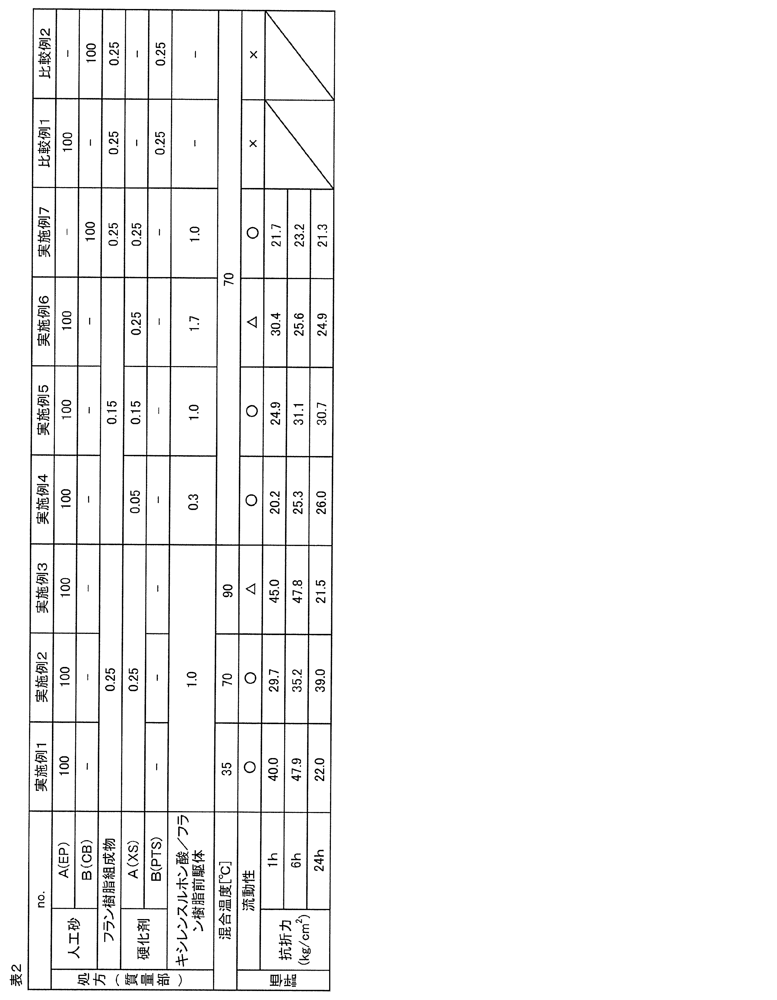
(実施例1~6)
人工砂A(ムライト砂、商品名:エスパール#100DAM、山川産業社製)と、表1に示すフラン樹脂組成物(樹脂組成物)とを準備した。人工砂Aは、カリ長石およびソーダ長石を含有していた。人工砂AのAFS(粒度指数)は、106.4であった。
人工砂A(ムライト砂、商品名:エスパール#100DAM、山川産業社製)と、表1に示すフラン樹脂組成物(樹脂組成物)とを準備した。人工砂Aは、カリ長石およびソーダ長石を含有していた。人工砂AのAFS(粒度指数)は、106.4であった。
次いで、人工砂A100質量部を、表2に示す混合温度に予熱した後、フラン樹脂組成物を表2に示す処方で添加して、人工砂Aとフラン樹脂組成物とが均一になるまで撹拌混合した(樹脂混合工程)。
その後、フラン樹脂組成物が混合された人工砂Aに、キシレンスルホン酸(XS)を含む硬化剤Aを表2に示す処方で添加して、硬化剤Aが添加された人工砂Aが円滑に流動するまで撹拌混合した(硬化剤混合工程)。
硬化剤Aは、キシレンスルホン酸を含有していた。キシレンスルホン酸の濃度は、硬化剤の全量に対して、95.0質量%以上97.0質量%以下であった。また、硬化剤混合工程では、表2に示す混合温度+5~10℃の温度範囲に維持された。
これによって、人工砂Aと、人工砂Aを被覆するフラン樹脂を含有する表面改質層と、表面改質層に付着する硬化剤Aとを備える鋳物砂を得た。
(実施例7)
人工砂Aを、人工砂B(ムライト砂、商品名:セラビーズ#1450、伊藤忠セラテック社製)に変更したこと以外は、実施例2と同様にして鋳物砂を得た。なお、人工砂Bは、カリ長石およびソーダ長石を含有していた。人工砂BのAFS粒度指数は、108.8であった。
人工砂Aを、人工砂B(ムライト砂、商品名:セラビーズ#1450、伊藤忠セラテック社製)に変更したこと以外は、実施例2と同様にして鋳物砂を得た。なお、人工砂Bは、カリ長石およびソーダ長石を含有していた。人工砂BのAFS粒度指数は、108.8であった。
(比較例1)
硬化剤Aを、パラトルエンスルホン酸(PTS)を含む硬化剤Bに変更したこと以外は、実施例2と同様にして鋳物砂を得た。硬化剤Bは、パラトルエンスルホン酸と、硫酸と、水とを含有していた。パラトルエンスルホン酸の濃度は、硬化剤Bの全量に対して、63質量%、硫酸の濃度は、硬化剤Bの全量に対して、1.0質量%であった。
硬化剤Aを、パラトルエンスルホン酸(PTS)を含む硬化剤Bに変更したこと以外は、実施例2と同様にして鋳物砂を得た。硬化剤Bは、パラトルエンスルホン酸と、硫酸と、水とを含有していた。パラトルエンスルホン酸の濃度は、硬化剤Bの全量に対して、63質量%、硫酸の濃度は、硬化剤Bの全量に対して、1.0質量%であった。
(比較例2)
硬化剤Aを、パラトルエンスルホン酸(PTS)を含む硬化剤Bに変更したこと以外は、実施例7と同様にして鋳物砂を得た。
<流動性評価>
各実施例および各比較例で得られた鋳物砂と、表1に示すバインダとを、3次元積層造形装置(商品名:S-Print、ExOne社製)にセットし、リコータによる鋳物砂の層形成、および、ジェットヘッドによるバインダの添加を順次繰り返して、砂型を造形した。なお、各鋳物砂の層の厚みは、0.28mmであった。また、リコータにおける突出部の遊端部と第2壁との間の間隔L(図3参照)は、鋳物砂が実施例1~6および比較例1である場合(人工砂Aである場合)、1.0mmであり、鋳物砂が実施例7および比較例2である場合(人工砂Bである場合)、1.4mmであった。
そして、鋳物砂の層形成および積層を下記の基準により評価した。その結果を表2に示す。
○:鋳物砂の層を精度よく形成でき、かつ、鋳物砂の層を精度よく積層できた。
△:鋳物砂の層の一部に乱れが生じたが、砂型の造形には問題がなかった。
×:鋳物砂がリコータから流出し、鋳物砂をリコータ内に維持できず、砂型を造形できなかった。
<抗折力試験>
流動性評価と同様にして、各実施例および各比較例で得られた鋳物砂を用いて、図8Aに示すように、一辺Dが22.4mm、長さLが147mmである正四角柱の試験柱を調製した。
<抗折力試験>
流動性評価と同様にして、各実施例および各比較例で得られた鋳物砂を用いて、図8Aに示すように、一辺Dが22.4mm、長さLが147mmである正四角柱の試験柱を調製した。
その試験柱を、室温24℃、湿度45%の条件下で、表2に示す各時間放置した。
そして、図8Bに示すように、試験柱を、試験柱の長さ方向外側から挟み込むように、試験装置(Universal Strength Machine PFG、シンプソン社製)にセットした。
次いで、試験柱の一端を固定して、試験柱に対して他方側から、試験柱の長さ方向に沿って、試験柱に圧力を加えた。そして、試験柱が折れたときの圧力を抗折力とした。そして、上記の抗折力試験を3~5回繰り返して、表2に示す各時間における抗折力の平均値を算出した。その結果を表2に示す。

1 鋳物砂
2 人工砂
3 表面改質層
なお、上記発明は、本発明の例示の実施形態として提供したが、これは単なる例示に過ぎず、限定的に解釈してはならない。当該技術分野の当業者によって明らかな本発明の変形例は、後記請求の範囲に含まれる。
2 人工砂
3 表面改質層
なお、上記発明は、本発明の例示の実施形態として提供したが、これは単なる例示に過ぎず、限定的に解釈してはならない。当該技術分野の当業者によって明らかな本発明の変形例は、後記請求の範囲に含まれる。
本発明の鋳物砂の製造方法は、各種産業製品の製造に利用される砂型の造形用の鋳物砂、とりわけ、3次元積層造形用の鋳物砂の製造に好適に用いることができる。本発明の鋳物砂は、各種産業製品の製造に利用される砂型、とりわけ、3次元積層造形により製造される砂型に好適に用いることができる。
Claims (4)
- 人工砂と、フラン樹脂前駆体を含むフラン樹脂組成物とを混合する工程と、
前記フラン樹脂組成物が混合された人工砂に硬化剤を混合する工程と、を含み、
前記硬化剤が、キシレンスルホン酸を含むことを特徴とする、鋳物砂の製造方法。 - 前記人工砂とフラン樹脂組成物とを混合する工程において、温度が100℃以下であることを特徴とする、請求項1に記載の鋳物砂の製造方法。
- キシレンスルホン酸の混合割合は、フラン樹脂前駆体1質量部に対して、0.3質量部以上3質量部以下であることを特徴とする、請求項1に記載の鋳物砂の製造方法。
- 人工砂と、
前記人工砂を被覆するフラン樹脂を含有する表面改質層と、
前記表面改質層に付着する硬化剤層と、を有し、
前記硬化剤層が、キシレンスルホン酸を含むことを特徴とする、鋳物砂。
Priority Applications (4)
| Application Number | Priority Date | Filing Date | Title |
|---|---|---|---|
| US16/471,437 US20200188989A1 (en) | 2017-02-28 | 2018-02-27 | Method for producing molding sand, and molding sand |
| CN201880005213.XA CN110290886B (zh) | 2017-02-28 | 2018-02-27 | 型砂的制造方法和型砂 |
| EP18761347.6A EP3590626A4 (en) | 2017-02-28 | 2018-02-27 | FOUNDRY SAND AND FOUNDRY SAND PRODUCTION PROCESS |
| US17/348,003 US11590561B2 (en) | 2017-02-28 | 2021-06-15 | Method of producing sand mold comprising curing a resin and a binder by the same curing agent |
Applications Claiming Priority (2)
| Application Number | Priority Date | Filing Date | Title |
|---|---|---|---|
| JP2017036487A JP6892284B2 (ja) | 2017-02-28 | 2017-02-28 | 砂型の製造方法および鋳物砂 |
| JP2017-036487 | 2017-02-28 |
Related Child Applications (2)
| Application Number | Title | Priority Date | Filing Date |
|---|---|---|---|
| US16/471,437 A-371-Of-International US20200188989A1 (en) | 2017-02-28 | 2018-02-27 | Method for producing molding sand, and molding sand |
| US17/348,003 Division US11590561B2 (en) | 2017-02-28 | 2021-06-15 | Method of producing sand mold comprising curing a resin and a binder by the same curing agent |
Publications (1)
| Publication Number | Publication Date |
|---|---|
| WO2018159616A1 true WO2018159616A1 (ja) | 2018-09-07 |
Family
ID=63370275
Family Applications (1)
| Application Number | Title | Priority Date | Filing Date |
|---|---|---|---|
| PCT/JP2018/007281 Ceased WO2018159616A1 (ja) | 2017-02-28 | 2018-02-27 | 鋳物砂の製造方法および鋳物砂 |
Country Status (5)
| Country | Link |
|---|---|
| US (2) | US20200188989A1 (ja) |
| EP (1) | EP3590626A4 (ja) |
| JP (1) | JP6892284B2 (ja) |
| CN (1) | CN110290886B (ja) |
| WO (1) | WO2018159616A1 (ja) |
Cited By (2)
| Publication number | Priority date | Publication date | Assignee | Title |
|---|---|---|---|---|
| US20240024949A1 (en) * | 2020-10-23 | 2024-01-25 | Bayerische Motoren Werke Aktiengesellschaft | Method for Producing a Molded Part, Molded Part and Method for Producing a Component |
| EP4063039A4 (en) * | 2019-11-22 | 2024-02-21 | Kinsei Matec Co., Ltd. | CASTING SAND AND SAND MOLD KIT |
Families Citing this family (12)
| Publication number | Priority date | Publication date | Assignee | Title |
|---|---|---|---|---|
| JP6892284B2 (ja) * | 2017-02-28 | 2021-06-23 | ダイハツ工業株式会社 | 砂型の製造方法および鋳物砂 |
| JP7142563B2 (ja) * | 2018-12-26 | 2022-09-27 | 伊藤忠セラテック株式会社 | 回収砂の再生方法 |
| JP7358055B2 (ja) * | 2019-02-19 | 2023-10-10 | 太平洋セメント株式会社 | 鋳型および型作製方法 |
| CN110586848A (zh) * | 2019-10-22 | 2019-12-20 | 康硕(德阳)智能制造有限公司 | 3d打印铸钢用砂型材料及其制备方法以及用该材料制做铸钢砂型的方法 |
| JP7101392B2 (ja) * | 2020-10-28 | 2022-07-15 | 株式会社清田鋳機 | 積層造形用鋳物砂及びその製造方法 |
| CN113020543B (zh) * | 2021-03-01 | 2023-03-21 | 潍柴动力股份有限公司 | 一种砂型芯成型方法及喷墨打印装置 |
| CN113979663B (zh) * | 2021-12-06 | 2022-06-24 | 广东浪淘砂新型材料有限公司 | 一种砂石调节剂及其制备方法及其应用 |
| CN114379082A (zh) * | 2021-12-22 | 2022-04-22 | 爱司达智能制造(江苏)有限公司 | 一种内部和表面同步增强增韧的3d打印砂型的制备方法 |
| WO2024102490A1 (en) * | 2022-11-11 | 2024-05-16 | ASK Chemicals LLC | Esters of epoxidized fatty acids in furfuryl alcohol binders |
| DE102023200590A1 (de) | 2023-01-25 | 2024-07-25 | Siemens Energy Global GmbH & Co. KG | Keramische Pulvermischung, Verfahren zum Herstellen eines keramischen Bauteils und Vorrichtung |
| WO2025263454A1 (ja) * | 2024-06-18 | 2025-12-26 | 花王株式会社 | 鋳型造型用硬化剤組成物 |
| JP7710696B1 (ja) | 2024-08-30 | 2025-07-22 | 株式会社清田鋳機 | 3次元積層造形用鋳物砂及びその製造方法 |
Citations (7)
| Publication number | Priority date | Publication date | Assignee | Title |
|---|---|---|---|---|
| JPS6163333A (ja) | 1984-09-05 | 1986-04-01 | Naigai Taika Kogyo Kk | 鋳物用鋳型材の製造方法 |
| JP2003251434A (ja) | 2002-02-28 | 2003-09-09 | Yamakawa Sangyo Kk | 鋳型用砂及びその製造方法 |
| WO2007110091A1 (de) * | 2006-03-25 | 2007-10-04 | Bayerische Motoren Werke Aktiengesellschaft | Bindemittelsystem |
| JP2009119469A (ja) * | 2007-11-12 | 2009-06-04 | Kimura Chuzosho:Kk | 自硬性流動鋳型 |
| JP2009285729A (ja) * | 2008-04-30 | 2009-12-10 | Kao Corp | 鋳型の製造方法 |
| JP2013240799A (ja) | 2012-05-17 | 2013-12-05 | Kimura Chuzosho:Kk | 三次元積層造型用の鋳物砂 |
| WO2016143050A1 (ja) * | 2015-03-09 | 2016-09-15 | 技術研究組合次世代3D積層造形技術総合開発機構 | 有機バインダ、粒状材料、3次元積層造形鋳型の製造装置および3次元積層造形鋳型の製造方法 |
Family Cites Families (10)
| Publication number | Priority date | Publication date | Assignee | Title |
|---|---|---|---|---|
| US3838095A (en) * | 1972-09-13 | 1974-09-24 | Cpc International Inc | Foundry sand coated with a binder containing novolac resin and urea compound |
| US4287092A (en) * | 1980-01-31 | 1981-09-01 | Cl Industries, Inc. | Acid catalysis of resin foundry binders |
| JPS62142048A (ja) * | 1985-12-13 | 1987-06-25 | Asahi Organic Chem Ind Co Ltd | 酸硬化型有機自硬性砂の製造方法 |
| US4713294A (en) * | 1986-05-23 | 1987-12-15 | Acme Resin Corporation | Foundry shell core and mold composition |
| JP4336474B2 (ja) | 2002-02-06 | 2009-09-30 | 株式会社木村鋳造所 | 自硬性流動鋳型造型法 |
| JP4672401B2 (ja) * | 2005-03-11 | 2011-04-20 | 花王株式会社 | 鋳型の製造方法 |
| DE102008024727A1 (de) * | 2008-05-23 | 2009-11-26 | Ashland-Südchemie-Kernfest GmbH | Methansulfonsäurehaltige Katalysatoren für das Säurehärtungsverfahren |
| CN101992260A (zh) * | 2010-11-05 | 2011-03-30 | 中国第一汽车集团公司 | 生产整体铸造桥壳用呋喃自硬树脂砂型 |
| JP5819551B1 (ja) * | 2015-02-18 | 2015-11-24 | 山川産業株式会社 | 人工砂及び鋳型用粘結剤含有砂 |
| JP6892284B2 (ja) * | 2017-02-28 | 2021-06-23 | ダイハツ工業株式会社 | 砂型の製造方法および鋳物砂 |
-
2017
- 2017-02-28 JP JP2017036487A patent/JP6892284B2/ja active Active
-
2018
- 2018-02-27 US US16/471,437 patent/US20200188989A1/en not_active Abandoned
- 2018-02-27 WO PCT/JP2018/007281 patent/WO2018159616A1/ja not_active Ceased
- 2018-02-27 EP EP18761347.6A patent/EP3590626A4/en not_active Withdrawn
- 2018-02-27 CN CN201880005213.XA patent/CN110290886B/zh not_active Expired - Fee Related
-
2021
- 2021-06-15 US US17/348,003 patent/US11590561B2/en active Active
Patent Citations (7)
| Publication number | Priority date | Publication date | Assignee | Title |
|---|---|---|---|---|
| JPS6163333A (ja) | 1984-09-05 | 1986-04-01 | Naigai Taika Kogyo Kk | 鋳物用鋳型材の製造方法 |
| JP2003251434A (ja) | 2002-02-28 | 2003-09-09 | Yamakawa Sangyo Kk | 鋳型用砂及びその製造方法 |
| WO2007110091A1 (de) * | 2006-03-25 | 2007-10-04 | Bayerische Motoren Werke Aktiengesellschaft | Bindemittelsystem |
| JP2009119469A (ja) * | 2007-11-12 | 2009-06-04 | Kimura Chuzosho:Kk | 自硬性流動鋳型 |
| JP2009285729A (ja) * | 2008-04-30 | 2009-12-10 | Kao Corp | 鋳型の製造方法 |
| JP2013240799A (ja) | 2012-05-17 | 2013-12-05 | Kimura Chuzosho:Kk | 三次元積層造型用の鋳物砂 |
| WO2016143050A1 (ja) * | 2015-03-09 | 2016-09-15 | 技術研究組合次世代3D積層造形技術総合開発機構 | 有機バインダ、粒状材料、3次元積層造形鋳型の製造装置および3次元積層造形鋳型の製造方法 |
Non-Patent Citations (1)
| Title |
|---|
| See also references of EP3590626A4 |
Cited By (3)
| Publication number | Priority date | Publication date | Assignee | Title |
|---|---|---|---|---|
| EP4063039A4 (en) * | 2019-11-22 | 2024-02-21 | Kinsei Matec Co., Ltd. | CASTING SAND AND SAND MOLD KIT |
| US20240024949A1 (en) * | 2020-10-23 | 2024-01-25 | Bayerische Motoren Werke Aktiengesellschaft | Method for Producing a Molded Part, Molded Part and Method for Producing a Component |
| US12151283B2 (en) * | 2020-10-23 | 2024-11-26 | Bayerische Motoren Werke Aktiengesellschaft | Method for producing a molded part, molded part and method for producing a component |
Also Published As
| Publication number | Publication date |
|---|---|
| EP3590626A1 (en) | 2020-01-08 |
| JP6892284B2 (ja) | 2021-06-23 |
| EP3590626A4 (en) | 2020-11-18 |
| US20200188989A1 (en) | 2020-06-18 |
| CN110290886A (zh) | 2019-09-27 |
| JP2018140422A (ja) | 2018-09-13 |
| CN110290886B (zh) | 2021-08-06 |
| US11590561B2 (en) | 2023-02-28 |
| US20210316356A1 (en) | 2021-10-14 |
Similar Documents
| Publication | Publication Date | Title |
|---|---|---|
| WO2018159616A1 (ja) | 鋳物砂の製造方法および鋳物砂 | |
| KR102438517B1 (ko) | 바인더 적층 가공 방법 | |
| CN106470780B (zh) | 逐层地构建包括耐火的模制基础材料和甲阶酚醛树脂的体部的方法 | |
| CN110719838B (zh) | 生产三维分层模具体的方法 | |
| JP6470542B2 (ja) | 積層鋳型の造型方法 | |
| JP6289648B1 (ja) | 粒状材料、粒状材料の製造方法および3次元積層造形鋳型の製造方法 | |
| WO2013171921A1 (ja) | 三次元積層造型用の鋳物砂 | |
| JP2015193035A (ja) | 三次元積層造形物の製造方法 | |
| JP7175822B2 (ja) | 砂組成物およびその製造方法と、鋳型の製造方法 | |
| JP6868333B2 (ja) | 砂型の製造方法および砂型 | |
| US5607986A (en) | Heat cured foundry mixes and their use | |
| JP6880302B1 (ja) | 鋳物砂および砂型用キット | |
| Nagai et al. | Additive manufacturing technology by furan sand mold using sintered artificial sand coated with solid catalyst | |
| JP2022075748A (ja) | 鋳造用砂型の製造方法 | |
| JP6868334B2 (ja) | 鋳物砂 | |
| Nagai et al. | Molding and mold properties of spherical artificial sand coated with inorganic binder | |
| JP6767899B2 (ja) | 再生砂の製造方法および鋳物砂の製造方法 | |
| JPS6131737B2 (ja) | ||
| CN114669718A (zh) | 黏结材积层制造的方法 | |
| JP7046752B2 (ja) | 砂組成物およびその製造方法と、3次元積層造形鋳型の製造方法 | |
| JP2021154307A (ja) | 付加製造装置用鋳物砂、および鋳物用砂型 | |
| JP6934417B2 (ja) | 耐火性粒子 |
Legal Events
| Date | Code | Title | Description |
|---|---|---|---|
| 121 | Ep: the epo has been informed by wipo that ep was designated in this application |
Ref document number: 18761347 Country of ref document: EP Kind code of ref document: A1 |
|
| NENP | Non-entry into the national phase |
Ref country code: DE |
|
| ENP | Entry into the national phase |
Ref document number: 2018761347 Country of ref document: EP Effective date: 20190930 |
|
| WWW | Wipo information: withdrawn in national office |
Ref document number: 2018761347 Country of ref document: EP |